JP2009201853A - Biological component concentration measuring apparatus - Google Patents
Biological component concentration measuring apparatus Download PDFInfo
- Publication number
- JP2009201853A JP2009201853A JP2008049078A JP2008049078A JP2009201853A JP 2009201853 A JP2009201853 A JP 2009201853A JP 2008049078 A JP2008049078 A JP 2008049078A JP 2008049078 A JP2008049078 A JP 2008049078A JP 2009201853 A JP2009201853 A JP 2009201853A
- Authority
- JP
- Japan
- Prior art keywords
- eardrum
- biological component
- actuator
- light
- component concentration
- Prior art date
- Legal status (The legal status is an assumption and is not a legal conclusion. Google has not performed a legal analysis and makes no representation as to the accuracy of the status listed.)
- Pending
Links
Images


Abstract
Description
本発明は、採血等を行なわずに非侵襲的に、生体成分の濃度、例えばグルコース濃度を測定する生体成分濃度測定装置に関するものである。 The present invention relates to a biological component concentration measuring apparatus that non-invasively measures a concentration of a biological component, for example, a glucose concentration, without performing blood sampling or the like.
従来、生体情報測定装置として、鼓膜からの放射光を計測して、グルコース濃度を算出する非侵襲血糖計が提案されている(例えば、特許文献1、2または3参照)。例えば、特許文献1には、外耳道に収まる程度の大きさの鏡を備え、その鏡を通して、近赤外線や熱線を鼓膜に照射するとともに、鼓膜において反射された光を検出し、検出結果からグルコース濃度を算出する非侵襲血糖計が開示されている。また、特許文献2には、耳孔内に挿入されるプローブを備え、鼓膜や外耳道を冷却した状態で、内耳より発生して鼓膜から放射された赤外線を、プローブを通して検出し、検出された赤外線を分光分析することによりグルコース濃度を得る非侵襲血糖計が開示されている。また、特許文献3には、耳孔内に挿入される反射鏡を備え、その反射鏡を用いて鼓膜からの放射光を検出し、検出された放射光を分光分析することによりグルコース濃度を得る非侵襲血糖計が開示されている。
しかし、鼓膜において反射された光を検出し、検出結果からグルコース濃度を算出する非侵襲血糖計において、高精度に測定するためには、鼓膜中の血液量が多い領域に光を照射する必要がある。鼓膜中の血液量が多いということは、それだけ、グルコースに由来する反射光が多く取得できるため好ましいが、前記従来の非侵襲血糖計ではこのような観点からの考慮はなく、生体成分濃度の測定におけるSNが悪いという問題があった。 However, in a non-invasive blood glucose meter that detects light reflected from the eardrum and calculates the glucose concentration from the detection result, it is necessary to irradiate light to a region where the amount of blood in the eardrum is large. is there. It is preferable that the amount of blood in the tympanic membrane is large because it is possible to acquire a large amount of reflected light derived from glucose. However, the conventional non-invasive blood glucose meter has no consideration from this point of view, and measures biological component concentrations. There was a problem that SN was bad.
本発明は、前記従来の問題点に鑑み、鼓膜からの反射光を用いて生体成分濃度を高精度に測定することができる生体成分濃度測定装置を提供することを目的とする。 In view of the above-described conventional problems, an object of the present invention is to provide a biological component concentration measuring apparatus capable of measuring biological component concentration with high accuracy using reflected light from the eardrum.
前記従来の課題を解決するために、本発明の生体成分濃度測定装置は、鼓膜中の血液量が多い領域を判断する血液量評価手段と、前記血液量評価手段により鼓膜中の血液量が多い領域に光を照射する光照射手段と、前記光照射手段により照射された光を検出する光検出器と、前記光検出器の出力から生体成分濃度を算出する生体情報演算部を備える。 In order to solve the above-described conventional problems, the biological component concentration measuring apparatus according to the present invention includes a blood volume evaluation unit for determining a region where the blood volume in the eardrum is large, and a blood volume in the eardrum is large by the blood volume evaluation unit. A light irradiating means for irradiating the region with light; a photodetector for detecting the light irradiated by the light irradiating means; and a biological information calculation unit for calculating a biological component concentration from the output of the photodetector.
本発明の生体成分濃度測定装置によれば、鼓膜からの反射光を用いて生体成分濃度を高精度に測定することができる。 According to the biological component concentration measuring apparatus of the present invention, the biological component concentration can be measured with high accuracy using the reflected light from the eardrum.
鼓膜中の血液量が多い領域を判断する血液量評価手段と、前記血液量評価手段により鼓膜中の血液量が多い領域に光を照射する光照射手段と、前記光照射手段により照射された光を検出する光検出器と、前記光検出器の出力から生体成分濃度を算出する生体情報演算部を備える。 Blood volume evaluation means for judging a region with a large amount of blood in the eardrum, light irradiation means for irradiating light to a region with a large amount of blood in the eardrum by the blood volume evaluation means, and light emitted by the light irradiation means And a biological information calculation unit for calculating a biological component concentration from the output of the photodetector.
本発明の生体成分濃度測定装置において、前記血液量評価手段は、ヘモグロビンに対して吸収を持つ波長の光を照射する光源と、
前記光源により照射された光の前記鼓膜による反射光を取得し前記鼓膜を撮像する撮像素子と、
前記撮像素子からの撮像情報に基づいて、前記鼓膜中の血液量の多寡を判定する判定部、
を備えることが好ましい。
In the biological component concentration measuring apparatus according to the present invention, the blood volume evaluation means includes a light source that irradiates light having a wavelength that absorbs hemoglobin,
An imaging device for acquiring reflected light from the eardrum of light irradiated by the light source and imaging the eardrum;
A determination unit that determines the amount of blood in the eardrum based on imaging information from the imaging element;
It is preferable to provide.
また、本発明の生体成分濃度測定装置において、前記撮像素子により得られた、前記撮像情報の各画素における前記反射光の強度に対応する出力と、所定の閾値を比較する比較部をさらに備え、前記判定部は、前記比較部による比較結果をさらに利用して、前記鼓膜中の血液量の多寡を判定してもよい。 The biological component concentration measurement apparatus of the present invention further includes a comparison unit that compares a predetermined threshold value with an output corresponding to the intensity of the reflected light in each pixel of the imaging information obtained by the imaging element. The determination unit may further determine the amount of blood in the eardrum using the comparison result by the comparison unit.
また、本発明の生体成分濃度測定装置において、前記所定の閾値を記憶する閾値記憶部をさらに備え、
前記所定の閾値は、前記反射光の強度に関して予め定められた値であり、
前記比較部は、前記撮像部により得られた前記撮像情報の各画素における前記反射光の強度に対応する出力と前記所定の閾値と比較してもよい。
The biological component concentration measurement apparatus of the present invention further includes a threshold storage unit that stores the predetermined threshold,
The predetermined threshold is a predetermined value with respect to the intensity of the reflected light,
The comparison unit may compare an output corresponding to the intensity of the reflected light in each pixel of the imaging information obtained by the imaging unit with the predetermined threshold.
また、本発明の生体成分濃度測定装置において、前記光源が照射する光の波長は、400〜450ナノメートルであることが好ましい。これは、血液中のヘモグロビンに対して吸収が強い波長であるため、より高精度に血液量評価が可能になる。 Moreover, in the biological component concentration measuring apparatus of the present invention, the wavelength of light emitted from the light source is preferably 400 to 450 nanometers. This is a wavelength that is strongly absorbed with respect to hemoglobin in the blood, so that the blood volume can be evaluated with higher accuracy.
また、本発明の生体成分濃度測定装置において、前記血液量評価手段は、さらに鼓膜からの反射光を集光するレンズと、前記レンズを光軸方向に駆動する第1のアクチュエータと前記第1のアクチュエータを制御する第1のアクチュエータ制御部とを備えることが好ましい。このようにすることにより、光軸方向にも撮像素子上に結像させることができるため、より高精度に血液量評価が可能になる。 In the biological component concentration measuring apparatus according to the present invention, the blood volume evaluation means further includes a lens that collects reflected light from the eardrum, a first actuator that drives the lens in the optical axis direction, and the first It is preferable to include a first actuator control unit that controls the actuator. By doing so, it is possible to form an image on the image sensor also in the optical axis direction, so that it is possible to evaluate the blood volume with higher accuracy.
また、本発明の生体成分濃度測定装置において、前記血液量評価手段は、前記第1のアクチュエータを駆動させながら、前記撮像素子により前記鼓膜を撮像し、前記撮像素子により得られた撮像情報を用いて、前記撮像情報の各画素の中から、前記鼓膜による反射光が前記撮像素子上に結像している画素を抽出する結像位置抽出部と、
前記レンズの移動量とを算出するレンズ移動量演算部とをさらに備えていてもよい。
Further, in the biological component concentration measuring apparatus of the present invention, the blood volume evaluation means images the eardrum with the imaging element while driving the first actuator, and uses imaging information obtained by the imaging element. An imaging position extraction unit that extracts a pixel in which reflected light from the eardrum forms an image on the imaging element from each pixel of the imaging information;
A lens movement amount calculation unit that calculates the movement amount of the lens may be further provided.
また、本発明の生体成分濃度測定装置において、前記光照射手段は、赤外線を発生する赤外光源と、前記赤外光源から出射した光を整形・集光するレンズと、前記赤外光源から出射した光の方向を変更するための光線方向変更手段を備える。 In the biological component concentration measuring apparatus according to the present invention, the light irradiation means includes an infrared light source that generates infrared light, a lens that shapes and collects light emitted from the infrared light source, and light emitted from the infrared light source. A light beam direction changing means for changing the direction of the emitted light.
また、本発明の生体成分濃度測定装置において、前記光線方向変更手段は、前記レンズを光軸に対して垂直方向に駆動する第2のアクチュエータと前記第2のアクチュエータを制御する第2のアクチュエータ制御部を備え、前記第2のアクチュエータを駆動することにより、前記赤外光源の鼓膜への照射位置を変更してもよい。このようにすることにより、鼓膜上の水平方向の照射位置を変更することができる。 Further, in the biological component concentration measuring apparatus according to the present invention, the light beam direction changing means includes a second actuator that drives the lens in a direction perpendicular to the optical axis and a second actuator control that controls the second actuator. An irradiation position of the infrared light source on the eardrum may be changed by driving the second actuator. By doing so, the irradiation position in the horizontal direction on the eardrum can be changed.
また、本発明の生体成分濃度測定装置において、前記光照射手段は、さらに前記レンズを光軸方向に駆動するための第3のアクチュエータと前記第3のアクチュエータを制御する第3のアクチュエータ制御部を備えていてもよい。このようにすることにより、さらに鼓膜の奥行き方向の照射位置を変更できるため好ましい。 In the biological component concentration measuring apparatus according to the present invention, the light irradiation means further includes a third actuator for driving the lens in the optical axis direction and a third actuator control unit for controlling the third actuator. You may have. This is preferable because the irradiation position in the depth direction of the eardrum can be further changed.
また、本発明の生体成分濃度測定装置において、前記第2のアクチュエータの駆動量を決定するアクチュエータ駆動量算出部をさらに備え、前記アクチュエータ駆動量算出部は、前記判定部により得られた前記鼓膜中の血液が多い領域に前記赤外光源から出射した光が照射されるように、前記撮像情報の前記鼓膜中の血液量が多いと判定された領域の画素の位置に関する情報に基づき前記第2のアクチュエータの駆動量を算出することが好ましい。このようにすることにより、鼓膜上の水平方向の照射位置を変更するためのアクチュエータ移動量を決定することができるため好ましい。 The biological component concentration measuring apparatus according to the present invention further includes an actuator drive amount calculation unit that determines a drive amount of the second actuator, wherein the actuator drive amount calculation unit is included in the eardrum obtained by the determination unit. Based on the information on the pixel position in the region where the blood volume in the eardrum is determined to be large in the imaging information so that light emitted from the infrared light source is irradiated to the region where there is a lot of blood It is preferable to calculate the driving amount of the actuator. This is preferable because the amount of actuator movement for changing the irradiation position in the horizontal direction on the eardrum can be determined.
また、本発明の生体成分濃度測定装置において、前記アクチュエータ駆動量算出部は、さらに、第3のアクチュエータの駆動量をさらに算出し、前記第3のアクチュエータ駆動量は、前記判定部により得られた前記鼓膜中の血液が多い領域に前記赤外光源から出射した光が照射されるように、前記結像位置抽出部と前記レンズ移動量演算部により得られたレンズ移動量と、前記撮像情報の前記鼓膜中の血液量が多いと判定された領域の画素の位置に関する情報により決定されてもよい。このようにすることにより、鼓膜上の奥行き方向の照射位置を変更するためのアクチュエータ移動量を決定することができるため好ましい。 In the biological component concentration measuring apparatus of the present invention, the actuator driving amount calculation unit further calculates a driving amount of a third actuator, and the third actuator driving amount is obtained by the determination unit. The lens movement amount obtained by the imaging position extraction unit and the lens movement amount calculation unit so that light emitted from the infrared light source is irradiated to a region where the blood in the eardrum is rich, and the imaging information It may be determined based on information regarding the pixel position in the region where the blood volume in the eardrum is determined to be large. This is preferable because the amount of actuator movement for changing the irradiation position in the depth direction on the eardrum can be determined.
また、本発明の生体成分濃度測定装置が、鼓膜から放射された赤外光を分光する分光素子をさらに備え、赤外線検出器が、分光素子により分光された赤外光を検出するように構成されていてもよい。 The biological component concentration measuring apparatus of the present invention further includes a spectroscopic element that splits infrared light emitted from the eardrum, and the infrared detector is configured to detect infrared light that is split by the spectroscopic element. It may be.
本発明において、ヘモグロビンに対して吸収をもつ波長の光を照射する光源としては、例えば、青色レーザ等の可視光レーザや、青色LED等を用いることができる。 In the present invention, for example, a visible light laser such as a blue laser, a blue LED, or the like can be used as a light source that irradiates light having a wavelength that absorbs hemoglobin.
撮像素子としては、例えば、CMOSやCCD等の画像素子を用いることができる。 As the image pickup element, for example, an image element such as a CMOS or a CCD can be used.
分光素子としては、赤外線を波長別に分けることのできるものであればよく、例えば、特定の波長領域の赤外線を透過させる光学フィルタ、マイケルソン干渉計、回折格子等を用いることができる。 Any spectroscopic element may be used as long as it can divide infrared rays by wavelength. For example, an optical filter that transmits infrared rays in a specific wavelength region, a Michelson interferometer, a diffraction grating, or the like can be used.
赤外線検出器としては、赤外領域の波長の光を検出できるものであればよく、例えば、焦電センサ、サーモパイル、ボロメータ、HgCdTe(MCT)検出器、ゴーレイセル等を用いることができる。 The infrared detector is not particularly limited as long as it can detect light having a wavelength in the infrared region. For example, a pyroelectric sensor, a thermopile, a bolometer, an HgCdTe (MCT) detector, a Golay cell, or the like can be used.
アクチュエータ制御部、結像位置抽出部、生体成分濃度演算部としては、例えば、CPU(Central Processing Unit)等のマイクロコンピュータを用いることができる。 For example, a microcomputer such as a CPU (Central Processing Unit) can be used as the actuator control unit, the imaging position extraction unit, and the biological component concentration calculation unit.
本発明の生体成分濃度測定装置は、前記耳孔内に挿入される導波管をさらに備え、前記導波管が、前記光源から出射した前記光と、前記耳孔内において反射した前記光と、前記鼓膜から放射された前記赤外光とを導く機能を有していてもよい。 The biological component concentration measuring apparatus of the present invention further includes a waveguide inserted into the ear hole, and the waveguide emits the light emitted from the light source, the light reflected in the ear hole, It may have a function of guiding the infrared light emitted from the eardrum.
本発明において、導波管としては、赤外線を導くことのできるものであればよく、例えば、中空管や、赤外線を伝送する光ファイバ等を用いることができる。中空管を用いる場
合、中空管の内表面に金の層を有することが好ましい。この金の層は、中空管の内面に金メッキを施したり、金を蒸着したりすることにより形成することができる。
In the present invention, any waveguide can be used as long as it can guide infrared rays. For example, a hollow tube or an optical fiber that transmits infrared rays can be used. When using a hollow tube, it is preferable to have a gold layer on the inner surface of the hollow tube. This gold layer can be formed by performing gold plating on the inner surface of the hollow tube or by depositing gold.
本発明の生体成分濃度測定装置は、前記耳孔内において反射した前記光及び前記鼓膜から放射した前記赤外光のうち、一方を透過させ、他方を反射させる光分割素子をさらに備えていてもよい。 The biological component concentration measuring apparatus of the present invention may further include a light splitting element that transmits one of the light reflected in the ear canal and the infrared light emitted from the eardrum and reflects the other. .
ここで、前記赤外線検出器と前記光分割素子との間に前記分光素子が配置されていてもよい。 Here, the spectroscopic element may be arranged between the infrared detector and the light splitting element.
本発明において、光分割素子としては、例えば、可視光及び赤外光のうち、一方を透過させ、他方を反射させる機能を有するハーフミラーを用いることができる。可視光を反射して、赤外線を透過するようにする場合、ハーフミラーの材質としては、例えば、ZnSe、CaF2、Si、Ge等を用いることができる。また、赤外線に対して透明な樹脂上に、膜厚数nmのアルミニウムや金からなる層を設けたものを用いてもよい。赤外線に対して透明な樹脂としては、例えば、ポリカーボネイトが挙げられる。 In the present invention, as the light splitting element, for example, a half mirror having a function of transmitting one of visible light and infrared light and reflecting the other can be used. In the case of reflecting visible light and transmitting infrared light, for example, ZnSe, CaF2, Si, Ge, or the like can be used as the material of the half mirror. Moreover, you may use what provided the layer which consists of aluminum and gold | metal | money of several nanometers thickness on resin transparent with respect to infrared rays. Examples of the resin that is transparent to infrared rays include polycarbonate.
本発明の生体成分濃度測定装置は、赤外線検出器の出力信号と生体成分濃度との相関を示す相関データを格納する記憶部、生体成分濃度演算部により換算された生体成分の濃度を表示する表示部、及び生体成分濃度測定装置が動作するための電力を供給する電源をさらに備えていてもよい。 The biological component concentration measuring apparatus of the present invention includes a storage unit that stores correlation data indicating the correlation between the output signal of the infrared detector and the biological component concentration, and a display that displays the concentration of the biological component converted by the biological component concentration calculation unit. And a power source for supplying power for operating the biological component concentration measuring apparatus.
生体成分濃度演算部は、記憶部から上記相関データを読み出し、これを参照することにより、赤外線検出器の出力信号を生体成分の濃度に変換してもよい。 The biological component concentration calculation unit may convert the output signal of the infrared detector into the concentration of the biological component by reading the correlation data from the storage unit and referring to the correlation data.
赤外線検出器の出力信号と生体成分濃度との相関を示す相関データは、例えば、既知の生体成分濃度(例えば、血糖値)を有する患者について赤外線検出器の出力信号を測定し、得られた赤外線検出器の出力信号と生体成分の濃度との相関を解析することにより取得することができる。 The correlation data indicating the correlation between the output signal of the infrared detector and the biological component concentration is obtained by measuring the output signal of the infrared detector for a patient having a known biological component concentration (for example, blood glucose level), for example. It can be obtained by analyzing the correlation between the output signal of the detector and the concentration of the biological component.
本発明において、記憶部としては、例えば、RAM、ROM等のメモリを用いることが
できる。
In the present invention, for example, a memory such as a RAM or a ROM can be used as the storage unit.
表示部としては、例えば、液晶等のディスプレイを用いることができる。 As the display unit, for example, a display such as a liquid crystal can be used.
電源としては、例えば、電池等を用いることができる。 As the power source, for example, a battery or the like can be used.
本発明の生体成分濃度測定装置により測定する生体成分の濃度としては、グルコース濃度(血糖値)、ヘモグロビン濃度、コレステロール濃度、中性脂肪濃度等が挙げられる。 Examples of the biological component concentration measured by the biological component concentration measuring apparatus of the present invention include glucose concentration (blood glucose level), hemoglobin concentration, cholesterol concentration, and neutral fat concentration.
以下、本発明の実施の形態について、図面を参照しながら詳細に説明する。 Hereinafter, embodiments of the present invention will be described in detail with reference to the drawings.
(実施の形態1)
図1は、実施の形態1に係る生体成分濃度測定装置100の外観を示す斜視図である。
(Embodiment 1)
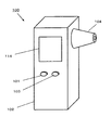
FIG. 1 is a perspective view showing an appearance of a biological component
生体成分濃度測定装置100は、本体102と、本体102の側面に設けられた導波管104を備えている。本体102には、生体成分の濃度の測定結果を表示するためのディスプレイ114、生体成分濃度測定装置100の電源をON/OFFするための電源スイッチ101、及び測定を開始するための測定開始スイッチ103が設けられている。
The biological component
ここで、ディスプレイ114は本発明における表示部に相当する。
Here, the
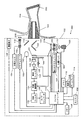
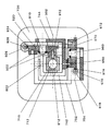
次に、生体成分濃度測定装置100の本体内部の構成について、図2及び図3を用いて説明する。図2は、実施の形態1に係る生体成分濃度測定装置100の構成を示す図であり、図3は、実施の形態1に係る生体成分濃度測定装置100における光学フィルタホイール106を示す斜視図である。
Next, the internal structure of the main body of the biological component
生体成分濃度測定装置100の本体内部には、チョッパー118、液晶シャッター120、光学フィルタホイール106、赤外線検出器108、前置増幅器130、帯域フィルタ132、同期復調器134、ローパスフィルタ136、アナログ/デジタルコンバータ(以下、A/Dコンバータと略称する)138、マイクロコンピュータ110、メモリ112、ディスプレイ114、電源116、光源140、第1のハーフミラー142、第2のハーフミラー144、集光レンズ146、撮像素子148、アクチュエータ150、レンズ枠152、位置センサ154、タイマー156、及びブザー158、赤外光源160、第3のハーフミラー162、第2のアクチュエータ164、第2の位置センサ166、レンズ枠168、レンズ170を備えている。
ここで、マイクロコンピュータ110は、本発明における結像位置算出部、アクチュエータ制御部、結像位置抽出部、判定部、アクチュエータ駆動量算出部及び生体成分濃度演算部に相当する。
Inside the main body of the biological component
Here, the
ここで、位置センサ154は、本発明におけるレンズ駆動量算出部に相当する。
Here, the
電源116は、マイクロコンピュータ110にACまたはDC電力を供給する。電源116として電池を用いることが好ましい。
The
赤外光源160は、鼓膜202に赤外光を照射するための赤外光を出射する。赤外光源160から出射され、第3のハーフミラー162により反射され、第2のハーフミラー144を透過した赤外光は、導波管104を通って外耳道204内に導かれ、鼓膜202を照射する。鼓膜202に到達した赤外光は、鼓膜202で反射し、生体成分濃度測定装置100側に反射光として放射される。この赤外光は、再び、導光管104、第2のハーフミラー144、第3のハーフミラー162を透過し、光学フィルタホイール106を通過し、赤外線検出器108で検出される。
The infrared
赤外光源160としては、公知のものを特に限定することなく適用することができる。例えば、シリコンカーバイド光源、セラミック光源、赤外LED、量子カスケードレーザ等を用いることができる。
As the infrared
第3のハーフミラー162は、赤外光を2光束に分割する機能を有する。第3のハーフミラー162の材質としては、例えば、ZnSe、CaF2、Si、Ge等を用いることができる。さらには、赤外線の透過率と反射率を制御する目的で、第3のハーフミラーに、反射防止膜が形成されていることが好ましい。
The third
チョッパー118は、鼓膜202から放射し、導波管104により本体102内に導かれた後、第2のハーフミラー144を透過した赤外光をチョッピングして、赤外光を高周波数の赤外線信号に変換する機能を有する。チョッパー118の動作は、マイクロコンピュータ110からの制御信号に基づき制御される。
The
チョッパー118によりチョッピングされた赤外光は、光学フィルタホイール106に到達する。
The infrared light chopped by the
光学フィルタホイール106は、図3に示すように、第1の光学フィルタ122及び第2の光学フィルタ124がリング123にはめ込まれている。図3に示す例では、ともに半円状である第1の光学フィルタ122及び第2の光学フィルタ124がリング123にはめ込まれることにより円盤状の部材が構成されており、その円盤状の部材の中央部にシャフト125が設けられている。このシャフト125を図3の矢印のように回転させることにより、チョッパー118によりチョッピングされた赤外光の通過する光学フィルタを、第1の光学フィルタ122と第2の光学フィルタ124との間で切り替えることができる。シャフト125の回転は、マイクロコンピュータ110からの制御信号により制御される。シャフト125の回転は、チョッパー118の回転と同期させ、チョッパー118が閉じている間にシャフト125を180度回転させるように制御することが好ましい。このようにすると、次にチョッパー118が開いたときに、チョッパー118によりチョッピングされた赤外光の通過する光学フィルタを別の光学フィルタに切り替えることができる。光学フィルタホイール106は、本発明における分光素子に相当する。
As shown in FIG. 3, the
光学フィルタの作製方法としては、公知の技術を特に限定することなく利用できるが、例えば、真空蒸着法を用いることができる。光学フィルタは、SiまたはGeを基板として、真空蒸着法を用いてZnS、MgF2、PbTe等を基板上に積層することにより作製することができる。 As a method for producing the optical filter, a known technique can be used without any particular limitation. For example, a vacuum deposition method can be used. The optical filter can be manufactured by stacking ZnS, MgF 2 , PbTe, or the like on the substrate by vacuum deposition using Si or Ge as the substrate.
ここで、基板上に積層する各層の膜厚、積層する順序、積層回数等を調節して、積層された薄膜内における光の干渉を制御することにより、所望の波長特性を持つ光学フィルタを作製することができる。 Here, an optical filter having a desired wavelength characteristic is manufactured by controlling the light interference in the laminated thin film by adjusting the film thickness of each layer laminated on the substrate, the order of lamination, the number of laminations, and the like. can do.
第1の光学フィルタ122及または第2の光学フィルタ124を透過した赤外光は、検出領域126を備える赤外線検出器108に到達する。赤外線検出器108に到達した赤外光は、検出領域126に入射し、入射した赤外光の強度に対応した電気信号に変換される。
The infrared light that has passed through the first
赤外線検出器108から出力された電気信号は、前置増幅器130によって増幅される。増幅された電気信号は、帯域フィルタ132によってチョッピング周波数を中心周波数とする周波数帯域以外の信号が取り除かれる。これにより、熱雑音等の統計的揺らぎに起因するノイズを最小化することができる。
The electrical signal output from the
帯域フィルタ132によって濾過された電気信号は、同期復調器134によってチョッパー118のチョッピング周波数と帯域フィルタ132によって濾過された電気信号を同期させ、積分することにより、DC信号に復調される。
The electric signal filtered by the
同期復調器134によって復調された電気信号は、ローパスフィルタ136によって低周波数帯域の信号が取り除かれる。これにより、さらにノイズを取り除くことができる。
The low-frequency band signal is removed from the electrical signal demodulated by the
ローパスフィルタ136によって濾過された電気信号は、A/Dコンバータ138によってデジタル信号に変換された後、マイクロコンピュータ110に入力される。ここで、各光学フィルタに対応する赤外検出器108からの電気信号は、シャフト125の制御信号をトリガーとして用いることで、どの光学フィルタを透過した赤外光に対応する電気信号であるのかを識別することができる。シャフト125の制御信号をマイクロコンピュータが出力してから、次のシャフト制御信号を出力するまでの間が、同じ光学フィルタに対応する電気信号となる。各光学フィルタに対応する電気信号を、それぞれメモリ112上で積算した後平均値を算出することにより、さらにノイズは低減されるため、測定の積算を行うことが好ましい。
The electrical signal filtered by the low-
メモリ112には、第1の光学フィルタ122を透過した赤外光の強度に対応する電気信号及び第2の光学フィルタ124を透過した赤外光の強度に対応する電気信号と生体成分の濃度との相関を示す相関データが格納されている。マイクロコンピュータ110は、メモリ112からこの相関データを読み出し、この相関データを参照して、メモリ112に蓄積されたデジタル信号から算出された単位時間当たりのデジタル信号を、生体成分の濃度に換算する。メモリ112は、本発明の記憶部に相当する。
In the
マイクロコンピュータ110において換算された生体成分の濃度は、ディスプレイ114に出力され、表示される。
The concentration of the biological component converted in the
第1の光学フィルタ122は、例えば、測定対象である生体成分によって吸収される波長を含む波長帯域(以下、測定用波長帯域と略称する)の赤外光を透過させるようなスペクトル特性を有する。一方、第2の光学フィルタ124は、第1の光学フィルタ122とは異なるスペクトル特性を有する。第2の光学フィルタ124は、例えば、測定対象である生体成分による吸収がなく、かつ対象成分の測定を妨害するような他の生体成分による吸収のある波長を含む波長帯域(以下、参照用波長帯域と略称する)の赤外光を透過させるようなスペクトル特性を有する。ここで、このような他の生体成分としては、測定対象である生体成分以外で、生体中における成分量の多いものを選択すればよい。
The first
例えば、グルコースは、9.6μm付近に吸収ピークを有する赤外吸収スペクトルを示
す。そこで、測定対象である生体成分がグルコースの場合は、第1の光学フィルタ122が、9.6μmを含む波長帯域の赤外光を透過させるようなスペクトル特性を有することが好ましい。
For example, glucose shows an infrared absorption spectrum having an absorption peak near 9.6 μm. Therefore, when the biological component to be measured is glucose, it is preferable that the first
一方、生体中に多く含まれるタンパク質は8.5マイクロメートル付近の赤外光を吸収し、グルコースは8.5μm付近の赤外光は吸収しない。そこで、第2の光学フィルタ124が、8.5μmを含む波長帯域の赤外光を透過させるようなスペクトル特性を有することが好ましい。
On the other hand, proteins that are abundant in the living body absorb infrared light around 8.5 micrometers, and glucose does not absorb infrared light around 8.5 μm. Therefore, it is preferable that the second
メモリ112に格納されている、第1の光学フィルタ122を透過した赤外光の強度に対応する電気信号及び第2の光学フィルタ324を透過した赤外光の強度に対応する電気信号と生体成分の濃度との相関を示す相関データは、例えば、以下の手順によって取得することができる。
The electrical signal corresponding to the intensity of the infrared light transmitted through the first
まず、既知の生体成分濃度(例えば、血糖値)を有する患者について、鼓膜から反射した赤外光を測定する。このとき、第1の光学フィルタ122が透過させる波長帯域における赤外光の強度に対応する電気信号と、第2の光学フィルタ124が透過させる波長帯域における赤外光の強度に対応する電気信号とを求める。この測定を、異なる生体成分濃度を有する複数の患者について行うことにより、第1の光学フィルタ122が透過させる波長帯域における赤外光の強度に対応する電気信号及び第2の光学フィルタ124が透過させる波長帯域における赤外光の強度に対応する電気信号と、それらに対応する生体成分濃度とからなるデータの組を得ることができる。
First, for a patient having a known biological component concentration (for example, blood glucose level), infrared light reflected from the eardrum is measured. At this time, an electrical signal corresponding to the intensity of infrared light in the wavelength band transmitted by the first
次に、このようにして取得したデータの組を解析して相関データを求める。例えば、第1の光学フィルタ122が透過させる波長帯域における赤外光の強度に対応する電気信号と、第2の光学フィルタ124が透過させる波長帯域における赤外光の強度に対応する電気信号と、それらに対応する生体成分濃度とについて、PLS(Partial Least Squares Regression)法などの重回帰分析法やニューラルネットワーク法などを用いて多変量解析を行うことにより、第1の光学フィルタ122が透過させる波長帯域における赤外光の強度に対応する電気信号及び第2の光学フィルタ124が透過させる波長帯域における赤外光の強度に対応する電気信号と、それらに対応する生体成分濃度との相関を示す関数を求めることができる。
Next, the data set thus obtained is analyzed to obtain correlation data. For example, an electrical signal corresponding to the intensity of infrared light in the wavelength band transmitted by the first
また、第1の光学フィルタ122が測定用波長帯域の赤外光を透過させるようなスペクトル特性を有し、第2の光学フィルタ124が参照用波長帯域の赤外光を透過させるようなスペクトル特性を有する場合、第1の光学フィルタ122が透過させる波長帯域における赤外光の強度に対応する電気信号と、第1の光学フィルタ324が透過させる波長帯域における赤外光の強度に対応する電気信号との差を求め、その差とそれに対応する生体成分濃度との相関を示す相関データを求めてもよい。例えば、最小二乗法等の直線回帰分析を行うことにより求めることができる。
The first
次に、鼓膜202を撮像するための構成について説明する。
Next, a configuration for imaging the
光源140は、鼓膜202を照明するための可視光を出射する。光源140から出射され、第1のハーフミラー142により反射された可視光は、第2のハーフミラー144により反射された後、導波管104を通って外耳道204内に導かれ、鼓膜202を照明する。
The
光源140としては、例えば、ヘモグロビンに対して吸収をもつ波長の光を照射する光源としては、例えば、青色レーザ等の可視光レーザや、青色LED等を用いることができる。この中で、青色LEDはハロゲンランプに比べ、発光させた時に発生する発生熱が少ないので、鼓膜202や外耳道204の温度に与える影響が少ないため好ましい。
As the
第1のハーフミラー142は、可視光の一部を反射し、残りを透過させる機能を有する。
The
第2のハーフミラー144は、可視光を反射して、赤外光を透過する。第2のハーフミラー144の材料としては、赤外線を吸収せず、透過し、可視光を反射する材料が好ましい。第2のハーフミラー144の材質としては、例えば、ZnSe、CaF2、Si、Ge等を用いることができる。ここで、第2のハーフミラー144は本発明における光分割素子に相当する。
The
一方、鼓膜202から外耳道204を通って導波管104内に入射した可視光は、第2のハーフミラー144により反射され、一部は第1のハーフミラー142を透過する。第1のハーフミラー142を透過した可視光は、レンズ枠152により保持されている集光レンズ146により集光され、撮像素子148に到達する。ここで、集光レンズ146は本発明におけるレンズに相当する。
On the other hand, visible light that has entered the
撮像素子148としては、例えば、CMOSやCCD等の画像素子を用いる。
As the
生体成分濃度測定装置100は、撮像素子148から鼓膜202まで距離を検出して、レンズ枠152に保持された集光レンズ146を駆動し、撮像素子148上に正しく光学像を結像させるための機構を備える。
The biological component
アクチュエータ150は、マイクロコンピュータ110からの制御信号によって駆動され、集光レンズ146を光軸の方向(図2中の矢印の方向)に移動させることができる。このとき、集光レンズ146の位置を位置センサ154が検出し、マイクロコンピュータ110に出力する。
The
一方、マイクロコンピュータ110は、撮像素子148の中央部付近の合焦エリア内に含まれる画素からの出力信号について、バンドパスフィルタにより信号の高域成分を抽出し、抽出された成分の大小からコントラスト量を検出する。マイクロコンピュータ110は、このコントラスト量が最大となる位置に集光レンズ146が移動するように、アクチュエータ150を制御する。
On the other hand, the
このようにして、鼓膜202までの距離が変化しても、撮像素子148上に鼓膜202の光学像が正しく結像することができる。この機構では、鼓膜202までの距離を直接測定しているわけではないが、集光レンズ146の位置情報から間接的に鼓膜202までの距離を測距していることになる。
In this way, even if the distance to the
アクチュエータ150及び位置センサ154としては、公知のビデオカメラやデジタルスチルカメラに搭載されているオートフォーカス装置において用いられているものと同様のものを用いることができる。例えば、アクチュエータ150としては、レンズ枠152に設けたコイルと、本体102側に固定されたヨーク、及びこのヨークに取付けられた駆動用マグネットとから構成することができる。レンズ枠152を、2本のガイドポールによって光軸方向に移動可能に支持しておき、レンズ枠152に設けたコイルに電流が供給されると、ヨークと駆動用マグネットとで形成される磁気回路中にあるコイルに対して、光軸方向の磁気推進力が生じ、レンズ枠152が光軸方向に移動する。推進力の正負の方向は、コイルに供給される電流の向きによって制御することができる。
As the
位置センサ154としては、例えば、一定ピッチで着磁され、レンズ枠152に取付けられたセンサマグネットと、本体102側に固定された磁気抵抗センサ(以下、MRセンサと略称する)とから構成することができる。本体102側に固定されたMRセンサにより、レンズ枠152に取付けられたセンサマグネットの位置を検出することにより、集光レンズ146の位置を検出することができる。
The
次に、撮像素子148により撮影された画像の中から、鼓膜202中の血液量を評価する方法について説明する。
Next, a method for evaluating the blood volume in the
図4は、撮像素子148を用いて、耳孔200内を観察した時の画像を示すイメージ図である。画像の左側が鼓膜202であり、右側に見えるのは外耳道204である。鼓膜202の見える位置や大きさは、個人によっても異なるが、導波管104の挿入位置によっても変わる。
FIG. 4 is an image diagram showing an image when the inside of the
次に、撮像素子148により撮影された画像を用いて、赤外線検出器108の赤外光が入射する面に対する鼓膜202の傾きの程度を見積もる方法について、図5〜8を用いて説明する。図5〜7は、撮像素子148により撮影された画像における鼓膜202に対応する部分の画素の状態を示す図である。
Next, a method for estimating the degree of inclination of the
マイクロコンピュータ110は、撮像素子148の画素のうち、上記の方法により鼓膜202を撮像していると認識された領域内に含まれる画素からの出力信号について、バンドパスフィルタにより信号の高域成分を抽出し、抽出された成分の大小からコントラスト量を検出する。マイクロコンピュータ110は、コントラスト量を閾値と比較して、コントラスト量が閾値以上である画素を、焦点が合っている状態であると認識する。
The
図5は、集光レンズ146が第1の位置にあるときに撮像素子148により撮影された画像における、鼓膜202に対応する部分の画素の状態を示す。マトリクス状に配置された複数の画素501のうち、黒色の部分は反射光が小さい部分の画素502であり、白色の部分は反射率が高い部分の画素503を示す。
FIG. 5 shows a state of a pixel in a portion corresponding to the
青色LEDの光は、ヘモグロビンに対して非常によく吸収されるため、ヘモグロビンが多い鼓膜の領域、すなわち、血液量が多い領域の青色LEDの反射光は小さくなる。したがって、図5に示した黒色の領域が血液量が多い領域となる。 The blue LED light is very well absorbed by hemoglobin, so the reflected light of the blue LED in the region of the eardrum where there is a lot of hemoglobin, that is, the region where the amount of blood is large, becomes small. Therefore, the black region shown in FIG. 5 is a region with a large blood volume.
このような鼓膜の撮像を集光レンズ146を駆動させながら行うことにより、鼓膜の奥行き方向においても同様に、鼓膜中の血液量が多い領域を評価する。
By performing such imaging of the eardrum while driving the condensing
このように鼓膜中の血液量が多い領域が得られた後、第2のアクチュエータの駆動量を決定する。第2のアクチュエータの駆動量の算出方法は、あらかじめ図5に示した一画素の距離分だけ駆動するための第2のアクチュエータの駆動量を算出しておき、図5で得られた画像で赤外光源から出射した光が、図5上の反射光が小さい領域の中心に当たるように第2のアクチュエータ駆動量を算出する。 After the region with a large amount of blood in the eardrum is obtained in this way, the driving amount of the second actuator is determined. The driving amount of the second actuator is calculated in advance by calculating the driving amount of the second actuator for driving by the distance of one pixel shown in FIG. 5, and using the image obtained in FIG. The second actuator driving amount is calculated so that the light emitted from the external light source hits the center of the region where the reflected light in FIG. 5 is small.
次に、本実施の形態における生体成分濃度測定装置100の動作について説明する。
Next, the operation of the biological component
まず、使用者が生体成分濃度測定装置100の電源スイッチ101を押すと、本体102内の電源がONとなり、生体成分濃度測定装置100は測定準備状態となる。
First, when the user presses the
次に、使用者が本体102を持って、導波管104を耳孔200内に挿入する。導波管104は、導波管104の先端部分から本体102との接続部分に向かって径が太くなるような円錐形状の中空管であるため、導波管104の外径が耳孔200の内径と等しくなる位置以上は導波管104が挿入されない構造になっている。
Next, the user holds the
次に、導波管104の外径が耳孔200の内径と等しくなる位置で生体成分濃度測定装置100を保持した状態で、使用者が生体成分濃度測定装置100の測定開始スイッチ103を押すと、本体102内の光源140がONとなり、撮像素子148による撮像を開始する。
Next, when the user presses the
次に、上記の方法により、撮像素子148により撮影された画像の中から、鼓膜202の位置を認識するステップが行われる。画像認識の結果、マイクロコンピュータ110が、撮像素子148により撮影された画像において、鼓膜202に相当する画像がないと判断した場合は、導波管104の挿入方向が鼓膜202からずれている旨のメッセージをディスプレイ114に表示したり、ブザー158を鳴らしたり、スピーカー(図示せず)から音声で出力したりすることにより、エラーであることを使用者に通知する。ここで、マイクロコンピュータ110により演算された、撮像された画像内における鼓膜の領域の割合が閾値以下である場合に、使用者にエラーであると通知するようにしてもよい。鼓膜202の位置が認識できないことを表すエラーが通知されると、使用者は生体成分濃度測定装置100を動かして、導波管104の挿入方向を調整すればよい。
Next, the step of recognizing the position of the
ここで、ディスプレイ114、ブザー158及びスピーカーは、それぞれ本発明における警告出力部に相当する。
Here, the
画像認識の結果、マイクロコンピュータ110が、撮像素子148により撮影された画像において、鼓膜202の位置を認識することができたと判断すると、上記の方法により第2のアクチュエータの駆動量を算出して、第2のアクチュエータ164を駆動することにより、赤外光源160の照射位置を調整する。
As a result of the image recognition, when the
また、マイクロコンピュータ110が、撮像素子148により撮影された画像において、鼓膜202の位置を認識することができたと判断すると、鼓膜202の位置を認識することができた旨のメッセージをディスプレイ114に表示したり、ブザー158を鳴らしたり、スピーカー(図示せず)から音声で出力したりすることにより使用者に通知する。
When the
鼓膜202の位置が認識されると、自動的に、鼓膜202から放射される赤外線の測定が開始される。鼓膜202の位置が認識されたことを使用者に通知することにより、使用者は、測定が開始されたことを把握することができるので、生体成分濃度測定装置100を動かさず、静止させればよいと認識することができる。
When the position of the
ここで、スピーカーは本発明における音声出力部に相当する。 Here, the speaker corresponds to an audio output unit in the present invention.
マイクロコンピュータ110が、撮像素子148により撮影された画像において、鼓膜202の位置を認識することができたと判断すると、液晶シャッター120の各液晶セルに印加する電圧を制御して、鼓膜202からの赤外光が入射する液晶セルを光が透過する状態に設定し、鼓膜202以外からの赤外光が入射する液晶セルを、光を遮断する状態に設定する。さらに、第2のアクチュエータ164を駆動することにより赤外光源160の照射位置の調整が完了すると、マイクロコンピュータ110がチョッパー118の動作を開始させることにより、鼓膜202から放射される赤外光の測定が開始される。
When the
赤外光の測定が開始された後も、撮像素子148により撮影された画像における鼓膜の位置を認識するための処理は継続して行っている。測定中に、使用者が導波管104を耳孔200から外に取り出してしまったり、導波管104の向きを大きく動かしてしまったりした場合には、マイクロコンピュータ110が、撮像素子148により撮影された画像において鼓膜202に相当する画像がないと判断することにより、使用者の誤操作を検知する。この検知に伴い、マイクロコンピュータ110は、導波管104の挿入方向が鼓膜202からずれている旨のメッセージをディスプレイ114に表示したり、ブザー158を鳴らしたり、スピーカー(図示せず)から音声で出力したりすることにより、エラーであることを使用者に通知する。さらに、マイクロコンピュータ110は、チョッパー118を制御して、光学フィルタホイール106に到達する赤外光を遮断することにより、自動的に測定を停止させる。ここで、マイクロコンピュータ110により演算された、撮像された画像内における鼓膜の領域の割合が閾値以下である場合に、使用者にエラーであると通知するようにしてもよい。
Even after the measurement of infrared light is started, the process for recognizing the position of the eardrum in the image photographed by the
鼓膜202の位置が認識できないことを表すエラーが通知されると、使用者は生体成分濃度測定装置100を動かして、導波管104を耳孔200内に再度挿入したり、導波管104の挿入方向を調整したりした後、測定開始スイッチ103を押すことにより、再度測定が開始される。
When an error indicating that the position of the
マイクロコンピュータ110は、タイマー156からの計時信号により、測定開始から一定時間経過したと判断すると、チョッパー118を制御して、光学フィルタホイール106に到達する赤外光を遮断する。これにより、自動的に測定が終了する。このとき、マイクロコンピュータ110はディスプレイ114やブザー158を制御して、測定が終了した旨のメッセージをディスプレイ114に表示したり、ブザー158を鳴らしたり、スピーカー(図示せず)から音声で出力したりすることにより、使用者に測定が終了したことを通知する。これにより使用者は測定が終了したことを確認することができるため、導波管104を耳孔200の外に取り出す。
When the
マイクロコンピュータ110は、メモリ112から、第1の光学フィルタ122を透過した赤外光の強度に対応する電気信号及び第2の光学フィルタ124を透過した赤外光の強度に対応する電気信号と生体成分の濃度との相関を示す相関データを読み出し、この相関データを参照して、補正後の電気信号を生体成分の濃度に換算する。求められた生体成分の濃度は、ディスプレイ114に表示される。
The
以上のように、本実施の形態に係る生体成分濃度測定装置100によると、鼓膜中の血液量が多い領域に赤外光源160から出射された光を照射することにより、鼓膜中の血液量が多い領域からの反射光を用いて測定できるため、SN比が向上させることができるため、生体成分濃度をより高精度に測定することができる。
As described above, according to the biological component
(実施の形態2)
図6は、実施の形態2に係る生体成分濃度測定装置300の外観を示す斜視図である。生体成分濃度測定装置300は、本体102と、本体102の側面に設けられた導波管104を備えている。本体102には、生体成分の濃度の測定結果を表示するためのディスプレイ114、生体成分濃度測定装置100の電源をON/OFFするための電源スイッチ101、及び測定を開始するための測定開始スイッチ103が設けられている。
(Embodiment 2)
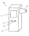
FIG. 6 is a perspective view showing an appearance of the biological component
ここで、ディスプレイ114は本発明における表示部に相当する。
Here, the
次に、本発明の実施の形態2に係る生体成分濃度測定装置の本体内部の構成について、図7を用いて説明する。図7は、実施の形態2に係る生体成分濃度測定装置300の構成を示す図である。
Next, the structure inside the main body of the biological component concentration measuring apparatus according to Embodiment 2 of the present invention will be described with reference to FIG. FIG. 7 is a diagram illustrating a configuration of the biological component
実施の形態1に係る生体成分濃度測定装置100と比較して異なる点は、生体成分濃度測定装置200の本体内部に、第3のアクチュエータ172を備えている点である。その他の構成は、実施の形態1に係る生体成分濃度測定装置100と同じであるため説明を省略する。
The difference from the biological component
青色LEDの光は、ヘモグロビンに対して非常によく吸収されるため、ヘモグロビンが多い鼓膜の領域、すなわち、血液量が多い領域の青色LEDの反射光は小さくなる。したがって、図5に示した黒色の領域が血液量が多い領域となる。 The blue LED light is very well absorbed by hemoglobin, so the reflected light of the blue LED in the region of the eardrum where there is a lot of hemoglobin, that is, the region where the amount of blood is large, becomes small. Therefore, the black region shown in FIG. 5 is a region with a large blood volume.
このような鼓膜の撮像を集光レンズ146を駆動させながら行うことにより、鼓膜の奥行き方向においても同様に、鼓膜中の血液量が多い領域を評価する。
By performing such imaging of the eardrum while driving the condensing
このように鼓膜中の血液量が多い領域が得られた後、第2のアクチュエータの駆動量を決定する。第2のアクチュエータの駆動量の算出方法は、あらかじめ図5に示した一画素の距離分だけ駆動するための第2のアクチュエータの駆動量を算出しておき、図5で得られた画像で赤外光源から出射した光が、図5上の反射光が小さい領域の中心に当たるように第2のアクチュエータ駆動量を算出する。 After the region with a large amount of blood in the eardrum is obtained in this way, the driving amount of the second actuator is determined. The driving amount of the second actuator is calculated in advance by calculating the driving amount of the second actuator for driving by the distance of one pixel shown in FIG. 5, and using the image obtained in FIG. The second actuator driving amount is calculated so that the light emitted from the external light source hits the center of the region where the reflected light in FIG. 5 is small.
さらに、レンズ移動量算出部、結像位置算出部により得られた前記第2のアクチュエータ駆動量を決定した際の画素における結像位置と、前記結像位置に達するのに必要なレンズ146におけるレンズ駆動量から第3のアクチュエータ駆動量を算出し、さらにの実の形態1に比較して鼓膜の奥行き方向にも赤外光源160の照射位置をあわしたものである。
Further, an image forming position in the pixel when the second actuator driving amount obtained by the lens moving amount calculating unit and the image forming position calculating unit is determined, and a lens in the
このようにすることより、鼓膜へ照射する赤外光源160からの鼓膜202上のエネルギー密度が上昇するため、より高精度な測定を行うことができる。
By doing in this way, since the energy density on the
メモリ112には、第1の光学フィルタ122を透過した赤外光の強度に対応する電気信号及び第2の光学フィルタ324を透過した赤外光の強度に対応する電気信号と生体成分の濃度との相関を示す相関データが格納されている。この相関データは、例えば、以下の手順によって取得することができる。
In the
まず、既知の生体成分濃度(例えば、血糖値)を有する患者について、赤外光源700から鼓膜に照射された赤外光が鼓膜において反射することにより鼓膜から放射される赤外光を測定する。このとき、第1の光学フィルタ122が透過させる波長帯域における赤外光の強度に対応する電気信号と、第2の光学フィルタ124が透過させる波長帯域における赤外光の強度に対応する電気信号とを求める。この測定を、異なる生体成分濃度を有する複数の患者について行うことにより、第1の光学フィルタ122が透過させる波長帯域における赤外光の強度に対応する電気信号及び第2の光学フィルタ124が透過させる波長帯域における赤外光の強度に対応する電気信号と、それらに対応する生体成分濃度とからなるデータの組を得ることができる。
First, with respect to a patient having a known biological component concentration (for example, blood glucose level), infrared light emitted from the eardrum is measured by reflection of infrared light irradiated on the eardrum from the infrared light source 700 on the eardrum. At this time, an electrical signal corresponding to the intensity of infrared light in the wavelength band transmitted by the first
次に、このようにして取得したデータの組を解析して相関データを求める。例えば、第1の光学フィルタ122が透過させる波長帯域における赤外光の強度に対応する電気信号と、第2の光学フィルタ124が透過させる波長帯域における赤外光の強度に対応する電気信号と、それらに対応する生体成分濃度とについて、PLS(Partial Least Squares Regression)法などの重回帰分析法やニューラルネットワーク法などを用いて多変量解析を行うことにより、第1の光学フィルタ122が透過させる波長帯域における赤外光の強度に対応する電気信号及び第2の光学フィルタ124が透過させる波長帯域における赤外光の強度に対応する電気信号と、それらに対応する生体成分濃度との相関を示す関数を求めることができる。
Next, the data set thus obtained is analyzed to obtain correlation data. For example, an electrical signal corresponding to the intensity of infrared light in the wavelength band transmitted by the first
本実施の形態のように、赤外光源160から鼓膜に照射された赤外光が鼓膜において反射することにより鼓膜から放射した赤外光を検出することにより、生体成分濃度を測定することが可能である。
As in the present embodiment, it is possible to measure the concentration of biological components by detecting the infrared light emitted from the eardrum when the infrared light irradiated from the infrared
次に、本実施の形態における生体成分濃度測定装置300の動作について説明する。
Next, the operation of the biological component
まず、使用者が生体成分濃度測定装置100の電源スイッチ101を押すと、本体102内の電源がONとなり、生体成分濃度測定装置100は測定準備状態となる。
First, when the user presses the
次に、使用者が本体102を持って、導波管104を耳孔200内に挿入する。導波管104は、導波管104の先端部分から本体102との接続部分に向かって径が太くなるような円錐形状の中空管であるため、導波管104の外径が耳孔200の内径と等しくなる位置以上は導波管104が挿入されない構造になっている。
Next, the user holds the
次に、導波管104の外径が耳孔200の内径と等しくなる位置で生体成分濃度測定装置100を保持した状態で、使用者が生体成分濃度測定装置100の測定開始スイッチ103を押すと、本体102内の光源140がONとなり、撮像素子148による撮像を開始する。
Next, when the user presses the
次に、上記の方法により、撮像素子148により撮影された画像の中から、鼓膜202の位置を認識するステップが行われる。画像認識の結果、マイクロコンピュータ110が、撮像素子148により撮影された画像において、鼓膜202に相当する画像がないと判断した場合は、導波管104の挿入方向が鼓膜202からずれている旨のメッセージをディスプレイ114に表示したり、ブザー158を鳴らしたり、スピーカー(図示せず)から音声で出力したりすることにより、エラーであることを使用者に通知する。ここで、マイクロコンピュータ110により演算された、撮像された画像内における鼓膜の領域の割合が閾値以下である場合に、使用者にエラーであると通知するようにしてもよい。鼓膜202の位置が認識できないことを表すエラーが通知されると、使用者は生体成分濃度測定装置100を動かして、導波管104の挿入方向を調整すればよい。
Next, the step of recognizing the position of the
ここで、ディスプレイ114、ブザー158及びスピーカーは、それぞれ本発明における警告出力部に相当する。
Here, the
画像認識の結果、マイクロコンピュータ110が、撮像素子148により撮影された画像において、鼓膜202の位置を認識することができたと判断すると、上記の方法により第2、第3のアクチュエータの駆動量を算出して、第2のアクチュエータ164、第3のアクチュエータ172を駆動することにより、赤外光源160の照射位置を調整する。
As a result of the image recognition, when the
また、マイクロコンピュータ110が、撮像素子148により撮影された画像において、鼓膜202の位置を認識することができたと判断すると、鼓膜202の位置を認識することができた旨のメッセージをディスプレイ114に表示したり、ブザー158を鳴らしたり、スピーカー(図示せず)から音声で出力したりすることにより使用者に通知する。
When the
鼓膜202の位置が認識されると、自動的に、鼓膜202から放射される赤外線の測定が開始される。鼓膜202の位置が認識されたことを使用者に通知することにより、使用者は、測定が開始されたことを把握することができるので、生体成分濃度測定装置100を動かさず、静止させればよいと認識することができる。
When the position of the
ここで、スピーカーは本発明における音声出力部に相当する。 Here, the speaker corresponds to an audio output unit in the present invention.
マイクロコンピュータ110が、撮像素子148により撮影された画像において、鼓膜202の位置を認識することができたと判断すると、液晶シャッター120の各液晶セルに印加する電圧を制御して、鼓膜202からの赤外光が入射する液晶セルを光が透過する状態に設定し、鼓膜202以外からの赤外光が入射する液晶セルを、光を遮断する状態に設定する。さらに、第2のアクチュエータ164を駆動することにより赤外光源160の照射位置の調整が完了すると、マイクロコンピュータ110がチョッパー118の動作を開始させることにより、鼓膜202から放射される赤外光の測定が開始される。
When the
赤外光の測定が開始された後も、撮像素子148により撮影された画像における鼓膜の位置を認識するための処理は継続して行っている。測定中に、使用者が導波管104を耳孔200から外に取り出してしまったり、導波管104の向きを大きく動かしてしまったりした場合には、マイクロコンピュータ110が、撮像素子148により撮影された画像において鼓膜202に相当する画像がないと判断することにより、使用者の誤操作を検知する。この検知に伴い、マイクロコンピュータ110は、導波管104の挿入方向が鼓膜202からずれている旨のメッセージをディスプレイ114に表示したり、ブザー158を鳴らしたり、スピーカー(図示せず)から音声で出力したりすることにより、エラーであることを使用者に通知する。さらに、マイクロコンピュータ110は、チョッパー118を制御して、光学フィルタホイール106に到達する赤外光を遮断することにより、自動的に測定を停止させる。ここで、マイクロコンピュータ110により演算された、撮像された画像内における鼓膜の領域の割合が閾値以下である場合に、使用者にエラーであると通知するようにしてもよい。
Even after the measurement of infrared light is started, the process for recognizing the position of the eardrum in the image photographed by the
鼓膜202の位置が認識できないことを表すエラーが通知されると、使用者は生体成分濃度測定装置100を動かして、導波管104を耳孔200内に再度挿入したり、導波管104の挿入方向を調整したりした後、測定開始スイッチ103を押すことにより、再度測定が開始される。
When an error indicating that the position of the
マイクロコンピュータ110は、タイマー156からの計時信号により、測定開始から一定時間経過したと判断すると、チョッパー118を制御して、光学フィルタホイール106に到達する赤外光を遮断する。これにより、自動的に測定が終了する。このとき、マイクロコンピュータ110はディスプレイ114やブザー158を制御して、測定が終了した旨のメッセージをディスプレイ114に表示したり、ブザー158を鳴らしたり、スピーカー(図示せず)から音声で出力したりすることにより、使用者に測定が終了したことを通知する。これにより使用者は測定が終了したことを確認することができるため、導波管104を耳孔200の外に取り出す。
When the
マイクロコンピュータ110は、メモリ112から、第1の光学フィルタ122を透過した赤外光の強度に対応する電気信号及び第2の光学フィルタ124を透過した赤外光の強度に対応する電気信号と生体成分の濃度との相関を示す相関データを読み出し、この相関データを参照して、補正後の電気信号を生体成分の濃度に換算する。求められた生体成分の濃度は、ディスプレイ114に表示される。
The
以上のように、本実施の形態に係る生体成分濃度測定装置100によると、鼓膜中の血液量が多い領域に赤外光源160から出射された光を照射することにより、鼓膜中の血液量が多い領域からの反射光を用いて測定できるため、SN比が向上させることができるため、生体成分濃度をより高精度に測定することができる。
As described above, according to the biological component
(実施の形態3)
次に、本発明の実施の形態3に係る生体情報測定システムについて説明する。
(Embodiment 3)
Next, a biological information measuring system according to Embodiment 3 of the present invention will be described.
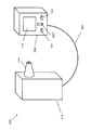
図8は、本実施の形態に係る生体情報測定システム500の外観を示す斜視図である。
FIG. 8 is a perspective view showing an appearance of biological
図8に示すように、本実施の形態に係る生体情報測定システム500は、挿入部104が設けられた測定部510と、ディスプレイ114、電源スイッチ101、測定開始スイッチ103及び方向調整レバースイッチ522が設けられた本体部520とを備えている。生体情報測定システム500において、測定部510と本体部520とは、電気信号を伝達するためのケーブル530により接続されている。
As shown in FIG. 8, the biological
次に、生体情報測定システム500における測定部510内部及び本体部520内部の構成について、図9を用いて説明する。図9は、生体情報測定システム500における測定部510内部及び本体部520内部の構成を示す図である。
Next, the internal structure of the
生体情報測定システム500における測定部510内部には、チョッパー118、光学フィルタホイール106、及び赤外線検出器108を含む検出ブロック512に加えて、光源140、レンズ146、レンズ枠152、第1のアクチュエータ150、位置センサ154、撮像素子148で構成される血液量評価手段、赤外光源160、第3のアクチュエータ172、第3の位置センサ174、レンズ170、レンズ枠168で構成される光照射手段及び赤外線検出器108の向きを調整するための可動部514を備えている。
In the
一方、生体情報測定システム500における本体部520内部には、前置増幅器130、帯域フィルタ132、同期復調器134、ローパスフィルタ136、A/Dコンバータ138、マイクロコンピュータ110、メモリ112、ディスプレイ114、電源116、タイマー156及びブザー158を備えている。
On the other hand, a
次に、図10〜図13を用いて、生体情報測定システム500における測定部510内部の構成について説明する。
Next, the internal configuration of the
図10は測定部510内部の構成を示す一部破断面図、図11は図10におけるA−A断面図、図12は図10におけるB−B線断面図、図13はカム部を設けた側から見たカムギア部の一例を示す平面図である。
10 is a partially broken cross-sectional view showing the internal configuration of the
図10に示すように、測定部510に備えられた挿入部104の内部には、外径形状が矩形形状である角柱部712と外径形状が円形形状である円柱部714とから構成される導光管710が設けられている。この導光管710の内部には、角柱部712及び角柱部714を貫通する導光路716が設けられている。また、導光管710の内部であって導光路716の外側には、導光路716の軸心718に対して傾斜した状態で、
導光管710の円柱部714側の端部は、挿入部104の耳孔に挿入される端部近くまで延伸され、導光管710の角柱部712側の端部は、検出ブロック512を保持するための検出ブロック用筐体720に連結されている。
As shown in FIG. 10, the
The end of the
検出ブロック用筐体720の内部には、光学フィルタホイール106、及び赤外線検出器108を含む検出ブロック512に加えて、光源140、レンズ146、レンズ枠152、第1のアクチュエータ150、位置センサ154、撮像素子148で構成される血液量評価手段、赤外光源160、第3のアクチュエータ172、第3の位置センサ174、レンズ170、レンズ枠168で構成される光照射手段、チョッパー118、及び赤外線検出器108が固定されており、光学フィルタホイール106が回転可能な状態で保持されている。
In the
耳孔内に挿入部104が挿入された状態で、挿入部104の端部から入射した赤外光が、導光管710の導光路716内を通った後、チョッパー118及び光学フィルタホイール106を介して赤外線検出器108に到達する位置に、検出ブロック用筐体720の内部においてチョッパー118、光学フィルタホイール106及び赤外線検出器108が配置されている。
In the state where the
図10及び11に示すように、導光管710における角柱部712の外側には、矩形の中空部を有する第1の支持部材本体742が設けられている。また、第1の支持部材本体742の外側には、矩形の中空部を有する第2の支持部材本体752が設けられている。
As shown in FIGS. 10 and 11, a first support member
図10のA−A部分において、図11に示すように、導光管710の角柱部712に設けられた第1の回動穴部810に、第1の支持部材本体742に固定された第1の回動支軸812が回動可能にはめ込まれている。この構成により、第1の支持部材本体742の中で、第1の回動支軸812を中心軸として導光管710の角柱部712が回転するように動作することが可能である。
In the AA portion of FIG. 10, as shown in FIG. 11, the first support member
また、第1の支持部材本体742に設けられた第2の回動穴部820に、第2の支持部材本体752に固定された第2の回動支軸822が回動可能にはめ込まれている。この構成により、第2の支持部材本体752の中で、第2の回動支軸822を中心軸として第1の支持部材本体742が回転するように動作することが可能である。
In addition, a second
図10に示すように、第2の支持部材本体752は支持部材本体730に固定され、その支持部材本体730は挿入部104に固定されている。
As shown in FIG. 10, the second support member
以上の構成により、導光管710と連結されている第1の支持部材本体742は、第2の回動支軸822を軸として挿入部104に対する傾斜角度を変えることが可能であり、導光管710は、第2の回動支軸822と直交する第1の回動支軸812を軸として挿入部104に対する傾斜角度を変えることが可能である。検出ブロック用筐体720は、導光管710の角柱部712側の端部に連結されているため、導光管710とともに動く。
With the above configuration, the first support member
次に、それぞれの支持部材の詳細な構成について述べる。図10及び図12に示すように、支持部材本体730に固定された第2の支持部材本体752と、この第2の支持部材本体752に固定して設けられた第2の支持部材側板部754とにより、第2の支持部材750が構成されている。また、第1の支持部材本体742と、この第1の支持部材本体742に固定された第1の支持部材側板部744とにより、第1の支持部材740が構成されている。
Next, a detailed configuration of each support member will be described. As shown in FIGS. 10 and 12, the second support member
次に、図10〜図13を用いて導光管710の傾斜角度を変えるための構成について詳細に説明する。
Next, a configuration for changing the inclination angle of the
図10のB−B部分において、図12に示すように、導光管710を構成する角柱部712には、導光路716の中心軸心902を通る位置に第1のカムフォロワー912が設けられている。第1のカムフォロワー912の軸心が第1の回動支軸812に平行となるように、第1のカムフォロワー912が配置されている。
10, a
第1の支持部材側板部744には、第1のカムギア軸910が植設され、第1のカムギア軸910の周りに回転可能に第1のカムギア部920が設けられている。また、第1カムギア部920には溝状に第1のカム部922が設けられ、この第1のカム部922には第1のカムフォロワー912が摺動可能に嵌り込んでいる。一方、第1のカムギア部920の外周部には第1のウオームホイールギア924が形成され、この第1のウオームホイールギア924に対して、第1の駆動モータ926に連結された第1のウオームギア928が係合している。第1の駆動モータ926が回転することにより、第1のウオームギア928及び第1のウオームホイールギア924を介して第1のカムギア部920が回動する。
A first
第1のカムギア部920が回動することにより、第1のカム部922に係合した第1のカムフォロワー912が第1のカム部922の溝に沿って移動し、導光管710を第1の回動支軸812の周りに回動させる。
As the first
一方、図10のB−B部分において、図12に示すように、第1の支持部材側板部744には、第2の回動支軸822に平行な軸心を有する第2のカムフォロワー950が設けられている。
On the other hand, in the BB portion of FIG. 10, as shown in FIG. 12, the first support
第2の支持部材側板部754には、第2のカムギア軸960が植設され、第2のカムギア軸960の周りに回転可能に第2のカムギア部970が設けられている。また、第2のカムギア部970には溝状に第2のカム部972が設けられ、この第2のカム部972には第2のカムフォロワー950が摺動可能に嵌り込んでいる。一方、第2のカムギア部970の外周部には第2のウオームホイールギア974が形成され、この第2のウオームホイールギア974に対して、第2の駆動モータ976に連結された第2のウオームギ978が係合している。第2の駆動モータ976が回転することにより、第2のウオームギア978及び第2のウオームホイールギア974を介して第2のカムギア部970が回動する。
A second
第2のカムギア部970が回動することにより、第2のカム部972に係合した第2のカムフォロワー950が第2のカム部972の溝に沿って移動し、第1の支持部材740を第2の回動支軸822を軸心として回動させる。
When the second
図13は、第1のカム部922を設けた側から見た第1のカムギア部920の一例を示す平面図である。図13(a)から図13(d)は、第1のカムギア部920が45°ずつ回転した場合の第1のカムフォロワー912の位置を示す。
FIG. 13 is a plan view showing an example of the first
図13に示すように、第1のカム部922は、第1のカムギア部920の回転中心Oから偏芯量εを有する点O1を中心とした円状に溝が設けられている。したがって、第1のカムギア部920が一回転すると、第1のカム部922に摺動可能に係合した第1のカムフォロワー912が上下に2εの距離分だけ移動する。
As shown in FIG. 13, the
したがって、図10において、第1の駆動モータ926が回転することにより、導光管710を構成する角柱部712に設けられた第1のカムフォロワー912を、第1の回転支軸812を支点として2εの範囲で上下移動させることができる。その結果、第1の回転支軸812を支点として、導光菅710の検出ブロック用筐体720と反対側の端部760を移動させることができる。第1の回動支軸812から第1のカムフォロワー912までの距離及び第1の回動支軸812から端部760までの長さを最適化することにより、導光管710の端部760の移動範囲を調整することができる。
Therefore, in FIG. 10, the
第2のカムギア部970でも同様の動作を行うことにより、第1のカムギア部920の動作による導光管710の端部760の移動と直交する方向において、導光管710の端部760を移動させることができる。
By performing the same operation in the second
したがって、第1の駆動モータ926及び第2の駆動モータ976の動作を制御することにより、導光管710の端部760が向いている方向を、耳孔内において2次元的に走査することができる。
Therefore, by controlling the operations of the
また、本発明の実施の形態では、導光管710の端部760が向いている方向を動かすために駆動モータを用い、さらに外乱に対しての影響の少ないウオームギア方式を採用している。そのため、導光管710の端部760が向いている方向を高精度に調整することが可能である。
In the embodiment of the present invention, a drive motor is used to move the direction in which the
次に、本実施の形態に係る生体情報測定システム500の動作について説明する。
Next, the operation of biological
まず、使用者が生体情報測定システム500の電源スイッチ101を押すと、本体部520内の電源がONとなり、生体情報測定システム500は測定準備状態となる。
First, when the user presses the
次に、使用者が一方の手で測定部510を持って、挿入部104を外耳道に挿入する。
Next, the user holds the
次に、使用者が生体情報測定システム500の測定開始スイッチ103を押すと、撮像素子148による撮像を開始する。耳孔内に挿入された挿入部104内部の導光管710の向きが不適切であることを報知するためにブザー158による警告音が鳴った場合、使用者は、挿入部104内部の導光管710の端面が鼓膜と対向するように、方向調整レバースイッチ522を操作して耳孔内における導光管710の向きを変更させる。このとき例えば、本体部520を保持している手とは反対側の手で方向調整レバースイッチ522を操作すればよい。ここで、例えば、図8において、方向調整レバースイッチ522を上方向に倒すことにより第1の駆動モータ926が駆動し、方向調整レバースイッチ522を下方向に倒すことにより第2の駆動モータ976が駆動し、方向調整レバースイッチ522が中立の位置にあるときには両方の駆動モータが停止するように設定しておけばよい。
Next, when the user presses the
以降の血液量の評価工程、赤外光の測定工程については、実施の形態2と同様であるため説明を省略する。 Since the subsequent blood volume evaluation step and infrared light measurement step are the same as those in the second embodiment, description thereof will be omitted.
本実施の形態に係る生体情報測定装置は、挿入部内部の導光管の向きを動かすための可動部を備えているので、耳孔内に挿入された挿入部内部の導光管が鼓膜の方向を向いていないと判定されたときに、測定部自体を動かす必要がなく、本体部に設けられた方向調整レバースイッチを操作するという容易な動作により導光管の向きを調整することができる。 Since the biological information measuring apparatus according to the present embodiment includes a movable part for moving the direction of the light guide tube inside the insertion part, the light guide tube inside the insertion part inserted into the ear canal is in the direction of the eardrum. When it is determined that the light guide tube is not directed, it is not necessary to move the measurement unit itself, and the direction of the light guide tube can be adjusted by an easy operation of operating a direction adjustment lever switch provided in the main body.
なお、本実施の形態においては、測定部510を一方の手で保持しながら赤外光の測定を行う形態について示したが、これに限定されない。例えば、測定部を耳または頭部に保持する測定部保持手段を測定部に設けて、測定部保持手段により測定部を耳または頭部に保持した状態で赤外光の測定を行ってもよい。測定部保持手段としては、例えば、耳に測定部を保持するためのクリップや、頭部に測定部を保持するためのヘッドバンド等が挙げられる。
In the present embodiment, an embodiment in which infrared light is measured while holding
本発明は、非侵襲的な生体成分濃度の測定、例えば、血液を採取することなくグルコ−ス濃度を測定する際に有用である。 The present invention is useful for non-invasive measurement of biological component concentration, for example, measuring glucose concentration without collecting blood.
100、300 生体成分濃度測定装置
101 電源スイッチ
102 本体
103 測定開始スイッチ
104 導波管
106 光学フィルタホイール
108 赤外線検出器
110 マイクロコンピュータ
112 メモリ
114 ディスプレイ
116 電源
118 チョッパー
120 液晶シャッター
122 第1の光学フィルタ
123 リング
124 第2の光学フィルタ
125 シャフト
126 検出領域
130 前置増幅器
132 帯域フィルタ
134 同期復調器
136 ローパスフィルタ
138 A/Dコンバータ
140 光源
142 第1のハーフミラー
144 第2のハーフミラー
146 集光レンズ
148 撮像素子
150 第1のアクチュエータ
152 レンズ枠
154 位置センサ
156 タイマー
158 ブザー
160 赤外光源
162 第3のハーフミラー
164 第2のアクチュエータ
166 第2の位置センサ
168 レンズ枠
170 レンズ
172 第3のアクチュエータ
174 第3の位置センサ
176 レンズ
200 耳孔
202 鼓膜
204 外耳道
500 生体成分濃度測定システム
501 画素
502 反射光が小さい領域の画素
503 反射光が大きい領域の画素
510 測定部
512 検出ブロック
514 可動部
520 本体部
522 方向調整レバースイッチ
530 ケーブル
710 導光管
712 角柱部
714 円柱部
716 導光路
718 軸心
720 検出ブロック用筐体
730 支持部材本体
740 第1の支持部材
742 第1の支持部材本体
744 第1の支持部材側板部
750 第2の支持部材
752 第2の支持部材本体
754 第2の支持部材側板部
760 端部
810 第1の回動穴部
812 第1の回動支軸
820 第2の回動穴部
822 第2の回動支軸
902 中心軸心
910 第1のカムギア軸
912 第1のカムフォロワー
920 第1のカムギア部
922 第1のカム部
924 第1のウオームホイールギア
926 第1の駆動モータ
928 第1のウオームギア
950 第2のカムフォロワー
960 第2のカムギア軸
970 第2のカムギア部
972 第2のカム部
974 第2のウオームホイールギア
976 第2の駆動モータ
978 第2のウオームギア
100, 300 Biological component concentration measuring apparatus 101 Power switch 102 Main body 103 Measurement start switch 104 Waveguide 106 Optical filter wheel 108 Infrared detector 110 Microcomputer 112 Memory 114 Display 116 Power supply 118 Chopper 120 Liquid crystal shutter 122 First optical filter 123 Ring 124 Second optical filter 125 Shaft 126 Detection region 130 Preamplifier 132 Band filter 134 Synchronous demodulator 136 Low pass filter 138 A / D converter 140 Light source 142 First half mirror 144 Second half mirror 146 Condensing lens 148 Image sensor 150 First actuator 152 Lens frame 154 Position sensor 156 Timer 158 Buzzer 160 Infrared light source 162 Third light Mirror 164 Second actuator 166 Second position sensor 168 Lens frame 170 Lens 172 Third actuator 174 Third position sensor 176 Lens 200 Ear hole 202 Tympanic membrane 204 External auditory canal 500 Biological component concentration measurement system 501 Pixel 502 Area where reflected light is small Pixel 503 Pixel in a region where reflected light is large 510 Measurement unit 512 Detection block 514 Movable unit 520 Main unit 522 Direction adjustment lever switch 530 Cable 710 Light guide tube 712 Square column part 714 Column part 716 Light guide path 718 Axis 720 Detection block housing Body 730 Support member body 740 First support member 742 First support member body 744 First support member side plate portion 750 Second support member 752 Second support member body 754 Second support member side plate portion 760 End 810 1st rotation hole 812 1st rotation support shaft 820 2nd rotation hole 822 2nd rotation support shaft 902 Center axis 910 1st cam gear shaft 912 1st cam follower 920 1st 1 cam gear portion 922 first cam portion 924 first worm wheel gear 926 first drive motor 928 first worm gear 950 second cam follower 960 second cam gear shaft 970 second cam gear portion 972 second Cam portion 974 Second worm wheel gear 976 Second drive motor 978 Second worm gear
Claims (12)
前記血液量評価手段により鼓膜中の血液量が多い領域に光を照射する光照射手段と、
前記光照射手段により照射された光を検出する光検出器と、
前記光検出器の出力から生体成分濃度を算出する生体情報演算部を備える生体成分濃度測定装置。 Blood volume evaluation means for judging an area where the blood volume in the eardrum is large;
A light irradiating means for irradiating light to a region with a large amount of blood in the eardrum by the blood volume evaluating means;
A photodetector for detecting the light irradiated by the light irradiation means;
A biological component concentration measurement apparatus comprising a biological information calculation unit that calculates a biological component concentration from an output of the photodetector.
前記光源により照射された光の前記鼓膜による反射光を取得し前記鼓膜を撮像する撮像素子と、
前記撮像素子からの撮像情報に基づいて、前記鼓膜中の血液量の多寡を判定する判定部、
を備える請求項1記載の生体成分濃度測定装置。 The blood volume evaluation means includes a light source that irradiates light having a wavelength that absorbs hemoglobin,
An imaging device for acquiring reflected light from the eardrum of light irradiated by the light source and imaging the eardrum;
A determination unit that determines the amount of blood in the eardrum based on imaging information from the imaging element;
The biological component concentration measuring apparatus according to claim 1, comprising:
前記判定部は、前記比較部による比較結果をさらに利用して、前記鼓膜中の血液量の多寡を判定する請求項2記載の生体成分濃度測定装置。 A comparator that compares the output obtained by the imaging element and corresponding to the intensity of the reflected light in each pixel of the imaging information with a predetermined threshold;
The biological component concentration measuring apparatus according to claim 2, wherein the determination unit further determines the amount of blood in the eardrum by further using a comparison result by the comparison unit.
前記所定の閾値は、前記反射光の強度に関して予め定められた値であり、
前記比較部は、前記撮像部により得られた前記撮像情報の各画素における前記反射光の強度に対応する出力と前記所定の閾値と比較する請求項3記載の生体成分濃度測定装置。 A threshold storage unit for storing the predetermined threshold;
The predetermined threshold is a predetermined value with respect to the intensity of the reflected light,
The biological component concentration measurement apparatus according to claim 3, wherein the comparison unit compares the output corresponding to the intensity of the reflected light in each pixel of the imaging information obtained by the imaging unit with the predetermined threshold.
前記レンズの移動量とを算出するレンズ移動量演算部とをさらに備える請求項6記載の生体成分濃度測定装置。 The blood volume evaluation means, while driving the first actuator, images the eardrum with the imaging element, and uses the imaging information obtained by the imaging element, from among each pixel of the imaging information, An imaging position extraction unit that extracts pixels in which reflected light from the eardrum forms an image on the image sensor;
The biological component concentration measurement apparatus according to claim 6, further comprising a lens movement amount calculation unit that calculates a movement amount of the lens.
前記赤外光源から出射した光を整形・集光するレンズと、
前記赤外光源から出射した光の方向を変更するための光線方向変更手段を備えることを特徴とする請求項1記載の生体成分濃度測定装置。 The light irradiation means includes an infrared light source that generates infrared rays;
A lens for shaping and collecting the light emitted from the infrared light source;
The biological component concentration measuring apparatus according to claim 1, further comprising a light beam direction changing unit for changing a direction of light emitted from the infrared light source.
前記アクチュエータ駆動量算出部は、前記判定部により得られた前記鼓膜中の血液が多い領域に前記赤外光源から出射した光が照射されるように、前記撮像情報の前記鼓膜中の血液量が多いと判定された領域の画素の位置に関する情報に基づき前記第2のアクチュエータの駆動量を算出する請求項9記載の生体成分濃度測定装置。 An actuator drive amount calculation unit for determining a drive amount of the second actuator;
The actuator driving amount calculation unit determines the amount of blood in the tympanic membrane of the imaging information so that light emitted from the infrared light source is irradiated to a region where the blood in the tympanic membrane is obtained by the determination unit. The biological component concentration measuring apparatus according to claim 9, wherein the driving amount of the second actuator is calculated based on information on the position of a pixel in a region determined to be large.
前記第3のアクチュエータ駆動量は、前記判定部により得られた前記鼓膜中の血液が多い領域に前記赤外光源から出射した光が照射されるように、前記結像位置抽出部と前記レンズ移動量演算部により得られたレンズ移動量と、前記撮像情報の前記鼓膜中の血液量が多いと判定された領域の画素の位置に関する情報により決定されることを特徴とする請求項7、10に記載の生体成分濃度測定装置。 The actuator drive amount calculation unit further calculates a drive amount of the third actuator,
The third actuator driving amount is such that the imaging position extracting unit and the lens movement are such that light emitted from the infrared light source is irradiated to a region where the blood in the eardrum obtained by the determining unit is rich in blood. 11. The amount of lens movement obtained by a quantity calculation unit and information relating to the position of a pixel in a region where it is determined that the amount of blood in the eardrum is large in the imaging information. The biological component concentration measuring apparatus as described.
Priority Applications (1)
| Application Number | Priority Date | Filing Date | Title |
|---|---|---|---|
| JP2008049078A JP2009201853A (en) | 2008-02-29 | 2008-02-29 | Biological component concentration measuring apparatus |
Applications Claiming Priority (1)
| Application Number | Priority Date | Filing Date | Title |
|---|---|---|---|
| JP2008049078A JP2009201853A (en) | 2008-02-29 | 2008-02-29 | Biological component concentration measuring apparatus |
Publications (1)
| Publication Number | Publication Date |
|---|---|
| JP2009201853A true JP2009201853A (en) | 2009-09-10 |
Family
ID=41144701
Family Applications (1)
| Application Number | Title | Priority Date | Filing Date |
|---|---|---|---|
| JP2008049078A Pending JP2009201853A (en) | 2008-02-29 | 2008-02-29 | Biological component concentration measuring apparatus |
Country Status (1)
| Country | Link |
|---|---|
| JP (1) | JP2009201853A (en) |
Cited By (6)
| Publication number | Priority date | Publication date | Assignee | Title |
|---|---|---|---|---|
| JP2016511019A (en) * | 2013-02-04 | 2016-04-14 | ヘレン オブ トロイ リミテッド | Method for identifying an object in a subject's ear |
| WO2017175779A1 (en) * | 2016-04-08 | 2017-10-12 | コニカミノルタ株式会社 | Optical measuring device, image generating method, and image generating program |
| US9931021B2 (en) | 2013-02-04 | 2018-04-03 | Helen Of Troy Limited | Method for identifying objects in a subject's ear |
| US10004386B2 (en) | 2013-02-04 | 2018-06-26 | Helen Of Troy Limited | Otoscope |
| US10172513B2 (en) | 2013-02-04 | 2019-01-08 | Helen Of Troy Limited | Otoscope |
| US11058286B2 (en) | 2013-02-04 | 2021-07-13 | Helen Of Troy Limited | Ear inspection device and method of determining a condition of a subject's ear |
-
2008
- 2008-02-29 JP JP2008049078A patent/JP2009201853A/en active Pending
Cited By (6)
| Publication number | Priority date | Publication date | Assignee | Title |
|---|---|---|---|---|
| JP2016511019A (en) * | 2013-02-04 | 2016-04-14 | ヘレン オブ トロイ リミテッド | Method for identifying an object in a subject's ear |
| US9931021B2 (en) | 2013-02-04 | 2018-04-03 | Helen Of Troy Limited | Method for identifying objects in a subject's ear |
| US10004386B2 (en) | 2013-02-04 | 2018-06-26 | Helen Of Troy Limited | Otoscope |
| US10172513B2 (en) | 2013-02-04 | 2019-01-08 | Helen Of Troy Limited | Otoscope |
| US11058286B2 (en) | 2013-02-04 | 2021-07-13 | Helen Of Troy Limited | Ear inspection device and method of determining a condition of a subject's ear |
| WO2017175779A1 (en) * | 2016-04-08 | 2017-10-12 | コニカミノルタ株式会社 | Optical measuring device, image generating method, and image generating program |
Similar Documents
| Publication | Publication Date | Title |
|---|---|---|
| JP4071822B2 (en) | Biological component concentration measuring device | |
| JP4189438B2 (en) | Biological component concentration measuring device | |
| JP4216893B2 (en) | Biological component concentration measuring device | |
| JP4199295B2 (en) | Biological information measuring device | |
| US7583380B2 (en) | Spectroscopic analysis apparatus and method with excitation system and focus monitoring system | |
| JP4264125B2 (en) | Biological information measuring apparatus and control method thereof | |
| EP1761816B1 (en) | Autofocus mechanism for spectroscopic system | |
| JP2009201853A (en) | Biological component concentration measuring apparatus | |
| US7817268B2 (en) | Alignment system for spectroscopic analysis | |
| US10436641B2 (en) | Shutter assembly for calibration | |
| JP2009178482A (en) | Biological information measuring apparatus | |
| JP2007144103A (en) | Biogenic substance density measuring instrument | |
| US20090116006A1 (en) | Biological information measuring sensor | |
| JP2007236734A (en) | Biological component concentration measuring apparatus | |
| CN101291619A (en) | Apparatus for measuring biological component concentration | |
| JP2010230662A (en) | Component measuring device | |
| JPH11128176A (en) | Organism optical measurement device | |
| US7453564B2 (en) | Method of determining a property of a fluid and spectroscopic system | |
| JP2007236732A (en) | Calibrator, biological component concentration measuring apparatus using it, and its calibration method | |
| US20060129036A1 (en) | Apparatus for the ph determination of blood and method therefor | |
| JP2007195653A (en) | Radiation spectral densitometer | |
| JP2012132745A (en) | Cholesterol concentration measuring apparatus | |
| CN107427265B (en) | Non-invasive method for measuring physiological parameters via confocal spectroscopic measuring device | |
| JP2022126704A (en) | Imaging apparatus, imaging method, program, and recording medium |