JP2009200876A - Band allocation method, station-side device, subscriber station device, communication system, and program of device - Google Patents
Band allocation method, station-side device, subscriber station device, communication system, and program of device Download PDFInfo
- Publication number
- JP2009200876A JP2009200876A JP2008041027A JP2008041027A JP2009200876A JP 2009200876 A JP2009200876 A JP 2009200876A JP 2008041027 A JP2008041027 A JP 2008041027A JP 2008041027 A JP2008041027 A JP 2008041027A JP 2009200876 A JP2009200876 A JP 2009200876A
- Authority
- JP
- Japan
- Prior art keywords
- allocation
- subscriber station
- bandwidth
- band
- bandwidth allocation
- Prior art date
- Legal status (The legal status is an assumption and is not a legal conclusion. Google has not performed a legal analysis and makes no representation as to the accuracy of the status listed.)
- Granted
Links
- 238000000034 method Methods 0.000 title claims description 39
- 238000004891 communication Methods 0.000 title claims description 28
- 230000005540 biological transmission Effects 0.000 claims abstract description 49
- 238000012545 processing Methods 0.000 claims description 14
- 230000003287 optical effect Effects 0.000 claims description 9
- 230000008569 process Effects 0.000 claims description 9
- 238000011144 upstream manufacturing Methods 0.000 description 14
- 238000010586 diagram Methods 0.000 description 10
- 230000006870 function Effects 0.000 description 7
- 230000008054 signal transmission Effects 0.000 description 5
- 238000005516 engineering process Methods 0.000 description 3
- 239000013307 optical fiber Substances 0.000 description 3
- 230000004927 fusion Effects 0.000 description 2
- 230000010354 integration Effects 0.000 description 2
- 101150012579 ADSL gene Proteins 0.000 description 1
- 102100020775 Adenylosuccinate lyase Human genes 0.000 description 1
- 108700040193 Adenylosuccinate lyases Proteins 0.000 description 1
- 101000878595 Arabidopsis thaliana Squalene synthase 1 Proteins 0.000 description 1
- 241001071864 Lethrinus laticaudis Species 0.000 description 1
- 230000002457 bidirectional effect Effects 0.000 description 1
- 238000004364 calculation method Methods 0.000 description 1
- 230000008859 change Effects 0.000 description 1
- 238000006243 chemical reaction Methods 0.000 description 1
- 230000003111 delayed effect Effects 0.000 description 1
- 230000000694 effects Effects 0.000 description 1
- 238000005259 measurement Methods 0.000 description 1
- 230000007246 mechanism Effects 0.000 description 1
- 239000002184 metal Substances 0.000 description 1
- 238000010295 mobile communication Methods 0.000 description 1
- 238000012986 modification Methods 0.000 description 1
- 230000004048 modification Effects 0.000 description 1
- 230000009467 reduction Effects 0.000 description 1
- 239000002699 waste material Substances 0.000 description 1
Images


Classifications
-
- H—ELECTRICITY
- H04—ELECTRIC COMMUNICATION TECHNIQUE
- H04J—MULTIPLEX COMMUNICATION
- H04J3/00—Time-division multiplex systems
- H04J3/16—Time-division multiplex systems in which the time allocation to individual channels within a transmission cycle is variable, e.g. to accommodate varying complexity of signals, to vary number of channels transmitted
- H04J3/1694—Allocation of channels in TDM/TDMA networks, e.g. distributed multiplexers
-
- G—PHYSICS
- G06—COMPUTING; CALCULATING OR COUNTING
- G06F—ELECTRIC DIGITAL DATA PROCESSING
- G06F9/00—Arrangements for program control, e.g. control units
- G06F9/06—Arrangements for program control, e.g. control units using stored programs, i.e. using an internal store of processing equipment to receive or retain programs
- G06F9/44—Arrangements for executing specific programs
- G06F9/445—Program loading or initiating
- G06F9/44505—Configuring for program initiating, e.g. using registry, configuration files
-
- H—ELECTRICITY
- H04—ELECTRIC COMMUNICATION TECHNIQUE
- H04B—TRANSMISSION
- H04B10/00—Transmission systems employing electromagnetic waves other than radio-waves, e.g. infrared, visible or ultraviolet light, or employing corpuscular radiation, e.g. quantum communication
- H04B10/25—Arrangements specific to fibre transmission
- H04B10/2575—Radio-over-fibre, e.g. radio frequency signal modulated onto an optical carrier
- H04B10/25752—Optical arrangements for wireless networks
- H04B10/25753—Distribution optical network, e.g. between a base station and a plurality of remote units
- H04B10/25754—Star network topology
-
- H—ELECTRICITY
- H04—ELECTRIC COMMUNICATION TECHNIQUE
- H04Q—SELECTING
- H04Q11/00—Selecting arrangements for multiplex systems
- H04Q11/0001—Selecting arrangements for multiplex systems using optical switching
- H04Q11/0062—Network aspects
- H04Q11/0067—Provisions for optical access or distribution networks, e.g. Gigabit Ethernet Passive Optical Network (GE-PON), ATM-based Passive Optical Network (A-PON), PON-Ring
-
- H—ELECTRICITY
- H04—ELECTRIC COMMUNICATION TECHNIQUE
- H04Q—SELECTING
- H04Q11/00—Selecting arrangements for multiplex systems
- H04Q11/0001—Selecting arrangements for multiplex systems using optical switching
- H04Q11/0062—Network aspects
- H04Q2011/0064—Arbitration, scheduling or medium access control aspects
-
- H—ELECTRICITY
- H04—ELECTRIC COMMUNICATION TECHNIQUE
- H04Q—SELECTING
- H04Q11/00—Selecting arrangements for multiplex systems
- H04Q11/0001—Selecting arrangements for multiplex systems using optical switching
- H04Q11/0062—Network aspects
- H04Q2011/0088—Signalling aspects
Landscapes
- Engineering & Computer Science (AREA)
- Computer Networks & Wireless Communication (AREA)
- Software Systems (AREA)
- Physics & Mathematics (AREA)
- Signal Processing (AREA)
- Theoretical Computer Science (AREA)
- Electromagnetism (AREA)
- General Engineering & Computer Science (AREA)
- General Physics & Mathematics (AREA)
- Small-Scale Networks (AREA)
- Mobile Radio Communication Systems (AREA)
Abstract
Description
本発明は、例えばPassive Optical Network(以下PONと表記)など、局側装置に複数の装置が接続されて構成されたシステムにおける帯域割当方法、局側装置、加入者局装置、通信システム、および装置のプログラムに関する。 The present invention relates to a bandwidth allocation method, a station side device, a subscriber station device, a communication system, and a device in a system configured by connecting a plurality of devices to a station side device such as a passive optical network (hereinafter referred to as PON). Related to the program.
近年、インターネットの急速な普及によりアクセス回線のブロードバンド化が進んでいる。ブロードバンドアクセス回線としては既にADSL、ケーブルモデム等のいろいろな方式が存在するが、より一層の広帯域化に向けてはPONが世界的に有望視されている。 In recent years, access lines have become broadband due to the rapid spread of the Internet. Various types of broadband access lines such as ADSL and cable modems already exist, but PON is promising worldwide for further broadbandization.
一方、メタル回線や光ファイバの敷設が困難な地域へのブロードバンド無線通信方式としてWorldwide Interoperability for Microwave Access(以下WiMAXと表記)が注目されている。最近ではシステムの簡素化ならびにコストダウンを目的として固定系通信と移動系通信の融合(Fixed Mobile Convergence:FMC)が提唱され、PONの加入者側にWiMAXを接続するネットワークが提案されている(非特許文献1参照)。 On the other hand, Worldwide Interoperability for Microwave Access (hereinafter referred to as WiMAX) is attracting attention as a broadband wireless communication system for areas where it is difficult to install metal lines or optical fibers. Recently, for the purpose of system simplification and cost reduction, the fusion of fixed communication and mobile communication (Fixed Mobile Convergence: FMC) has been proposed, and a network that connects WiMAX to the PON subscriber side has been proposed (non- Patent Document 1).
図24はPONの一般的な構成を示したものである。エンドユーザー宅には宅内装置ONU(Optical Network Unit)が設置され、局には局側装置OLT(Optical Line Terminator)が設置される。両者は光ファイバおよび光分岐結合器Optical Splitterを用いて接続される。各ユーザのパソコンはONUを介してネットワークに接続され、さらにOLTを経て上位ネットワーク及びインターネットに接続される。 FIG. 24 shows a general configuration of a PON. A home device ONU (Optical Network Unit) is installed at the end user's home, and a station side device OLT (Optical Line Terminator) is installed at the station. Both are connected using an optical fiber and an optical splitter. Each user's personal computer is connected to the network via the ONU, and further connected to the host network and the Internet via the OLT.
上り方向の信号(波長は通常1.3μm)と下り方向の信号(波長は通常1.5μm)は波長多重されるため、双方向1芯の光ファイバで接続される。下り方向の信号はOLTから全ONUにブロードキャストされ、各ONUはフレームの宛先をチェックし自装置宛のフレームを取り込む。 Since the upstream signal (wavelength is usually 1.3 μm) and the downstream signal (wavelength is usually 1.5 μm) are wavelength-multiplexed, they are connected by a bidirectional single-core optical fiber. The downstream signal is broadcast from the OLT to all ONUs, and each ONU checks the frame destination and captures the frame addressed to itself.
各ONUからの上り方向の信号はOptical Splitterで合流するが、この時、信号の衝突が起こらないようにするため、時分割多重が用いられる。そのため、OLTは各ONUから時々刻々報告される出力要求(REPORT)を調停し、OLT−ONU間の距離に基づく伝送時間を計算した上で各ONUに対して信号送出許可(GATE)を与える。 Upstream signals from each ONU are merged by an optical splitter, but at this time, time division multiplexing is used to prevent signal collision. Therefore, the OLT arbitrates an output request (REPORT) that is reported from time to time from each ONU, calculates a transmission time based on the distance between the OLT and the ONU, and gives a signal transmission permission (GATE) to each ONU.
出力要求(REPORT)にはバッファのキューの状態(待ち行列の長さ)が情報として含まれている。信号送出許可(GATE)には信号の優先度毎に送出開始時刻および送出継続時間が含まれており、ONUはこれに従って上り信号を送出する。すなわち上り方向の帯域割当はタイムスロットの割当として実現される。図25、図26はONTが3台接続された場合の信号の流れを示しており、図25が下り方向の信号、図26が上り方向の信号を示す。数字付きの四角が各ONU宛て並びに各ONU発の信号のフレームを示す。 The output request (REPORT) includes the queue status (queue length) of the buffer as information. The signal transmission permission (GATE) includes a transmission start time and a transmission continuation time for each signal priority, and the ONU transmits an upstream signal accordingly. That is, uplink bandwidth allocation is realized as time slot allocation. 25 and 26 show the signal flow when three ONTs are connected. FIG. 25 shows a downlink signal, and FIG. 26 shows an uplink signal. A square with a number indicates a frame of a signal addressed to each ONU and from each ONU.
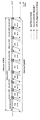
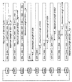
図27はONUとOLTの間で取り交わされる出力要求信号(REPORT)、出力許可信号(GATE)、上りデータ信号(DATA)の時間関係を示したものである。本図は1台のONUとOLTの間で取り交わされる信号を示しており、図中t1、t5はREPORTの送出時刻、t2、t4はGATEの到着時刻、Waiting Timeは信号送出までの待ち時間、Time Slotはデータ送出のタイムスロットを示す。REPORTはDATAの最後にpiggy backで送信される場合が多い。すなわち、その場合はt4=t5となる。 FIG. 27 shows the time relationship between the output request signal (REPORT), the output permission signal (GATE), and the upstream data signal (DATA) exchanged between the ONU and the OLT. This figure shows signals exchanged between one ONU and OLT. In the figure, t1 and t5 are REPORT transmission times, t2 and t4 are GATE arrival times, and Waiting Time is a waiting time until signal transmission. , Time Slot indicates a data transmission time slot. The REPORT is often transmitted by piggy back at the end of DATA. That is, in this case, t4 = t5.
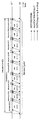
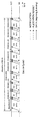
図28は3台のONU(ONU1、ONU2、ONU3)とOLTの間で取り交わされる信号の時間関係を示している。全てのONUの上り信号送信が一巡する周期をサービスサイクル(Service Cycle)と呼ぶ。サービスサイクルの長さは普通、一定とはせず、各ONUからの出力要求に応じて動的に変化させる場合が多い。 FIG. 28 shows the time relationship of signals exchanged between three ONUs (ONU1, ONU2, ONU3) and the OLT. A cycle in which upstream signal transmission of all ONUs makes a round is called a service cycle. The length of the service cycle is usually not constant, and is often dynamically changed according to an output request from each ONU.
イーサネット(登録商標)(Ethernet(登録商標))やPONに関してはIEEE802.3ahで標準化が行われており、REPORTメッセージとGATEメッセージに関しフレームフォーマットが規定されている。
しかしながら、上り方向の帯域割当方法やアルゴリズムについては規定されておらず、装置の実装に委ねられている。
Regarding Ethernet (registered trademark) and PON, standardization is performed in IEEE 802.3ah, and frame formats are defined for REPORT messages and GATE messages.
However, the bandwidth allocation method and algorithm in the upstream direction are not defined and are left to the implementation of the device.
図29はWiMAXのシステム構成を示す図である。BS(Base Station)とSS(Subscribers Station)は、それぞれ基地局(あるいは親局)、加入者局(あるいは子局)と呼ばれる。前者はサービスプロバイダ側に設置され後者はユーザ宅内に設置される。基地局装置BSと加入者局装置SSは無線によって結ばれ、加入者にインターネット接続等のサービスを提供する。 FIG. 29 is a diagram illustrating a system configuration of WiMAX. BS (Base Station) and SS (Subscribers Station) are called a base station (or a master station) and a subscriber station (or a slave station), respectively. The former is installed on the service provider side, and the latter is installed in the user's home. The base station apparatus BS and the subscriber station apparatus SS are connected by radio and provide services such as Internet connection to the subscriber.
WiMAXの仕様はIEEE802.16シリーズによって規定されている。物理層における周波数帯域や変調方式にはいくつかの種類があるが、MAC層は共通であり上り信号と下り信号は時分割で切り替えられ、さらに複数のSSの信号(上りおよび下り)も時分割で多重される。 The WiMAX specification is defined by the IEEE 802.16 series. There are several types of frequency bands and modulation schemes in the physical layer, but the MAC layer is common, and uplink and downlink signals are switched in a time division manner, and multiple SS signals (uplink and downlink) are also time division. Is multiplexed.
下り方向の信号はPONと同様にBSから全SSにブロードキャストされ、各SSはフレームの宛先をチェックし自装置宛のフレームを取り込む。上り信号も基本的にはPONと同様でありSSからの帯域割当要求をBSで調停し割当結果をSSに返送する。 The downstream signal is broadcast from the BS to all SSs in the same manner as the PON, and each SS checks the destination of the frame and takes in the frame addressed to itself. The uplink signal is basically the same as that of the PON, and the bandwidth allocation request from the SS is arbitrated by the BS, and the allocation result is returned to the SS.
一般に、PONの上り方向の帯域割当に関してはOLTに搭載された帯域割当機能部(Allocation Module、以下、本文及び図においてAMと表記)が各ONUからの要求に基づいて集中的に行っている。また、WiMAXの上り方向の帯域割当に関してもBSに搭載された帯域割当機能部(AM)が各SSからの要求に基づいて集中的に行っていた。 In general, the bandwidth allocation function unit (Allocation Module, hereinafter referred to as AM in the text and the figure) installed in the OLT is intensively performed based on the request from each ONU for the bandwidth allocation in the PON upstream direction. In addition, the bandwidth allocation function unit (AM) installed in the BS also performs concentrated bandwidth allocation in the uplink for WiMAX based on requests from each SS.
Ethernet PON(以下EPONと表記)とWiMAXの方式上の最も大きな違いは前者がコネクションレス型の通信方式であるのに対し、後者はコネクション型の通信方式である点である。すなわち、EPONは帯域割当要求に関してキュークラスベースであるのに対し、WiMAXはコネクションベースとなる。 The biggest difference between Ethernet PON (hereinafter referred to as EPON) and WiMAX is that the former is a connectionless communication method, whereas the latter is a connection type communication method. That is, EPON is queue class based on bandwidth allocation requests, whereas WiMAX is connection based.
図30はEPONとWiMAXが融合されたネットワークの構成を示している。PONの各ONUの配下にWiMAXが収容される構成となっている。ONUとBSはひとつの宅内中継装置として統合される。この宅内中継装置を以下、ONU−BSと呼ぶこととする。 FIG. 30 shows a network configuration in which EPON and WiMAX are merged. WiMAX is accommodated under each ONU of the PON. The ONU and BS are integrated as one in-home relay device. Hereinafter, this in-home relay device will be referred to as ONU-BS.
また、本出願人による関連技術として、アクセスポイントが携帯端末と無線で接続し、アクセス回線接続装置がその携帯端末によるインターネットへのアクセスを可能にし、加入者によるインターネットへのアクセスとは分離してパケットをルーティングするようにしたものがある(例えば、特許文献1参照)。
上述したWiMAXとEPONが接続されたネットワークにおいては、WiMAXの上り方向の帯域割当要求をONU−BSにおいてEPONの要求に変換する必要がある。
ここで、先に述べたようにEPONのキュークラスベースとコネクションベースとでは親和性が低いため、OLTにおける帯域割当において末端のSSの要求を効率的かつ精度よく反映させることが困難であった。
In a network in which WiMAX and EPON are connected as described above, it is necessary to convert a bandwidth allocation request in the uplink direction of WiMAX into an EPON request in the ONU-BS.
Here, since the affinity between the EPON queue class base and the connection base is low as described above, it is difficult to efficiently and accurately reflect the request of the terminal SS in the bandwidth allocation in the OLT.
さらにSSやONUの数が増えるにつれてBSとOLTにおける帯域割当処理の負荷が増し、スケーラビリティの問題が生じてくる。すなわち従来の割当方式では全てのSSまたはONUから割当要求を収集した後、次のサービスサイクルが始まるまでの間に集中して割当を行うため、SSまたはONUの数が多い場合、制御回路に過大な負荷をかけることになる。すなわち、大規模なWiMAXやPONでは制御回路に高価で高速な集積回路やCPUを要することになりシステムのコストアップにつながってしまう虞があった。
計算時間に余裕を持たせるとサービスサイクルの開始が遅れて帯域が無駄になり性能が低下する。
Further, as the number of SSs and ONUs increases, the load of bandwidth allocation processing in the BS and OLT increases, resulting in a scalability problem. That is, in the conventional allocation method, allocation requests are concentrated from the collection of allocation requests from all SSs or ONUs until the next service cycle starts. Therefore, if the number of SSs or ONUs is large, the control circuit is excessively large. A heavy load. That is, a large-scale WiMAX or PON requires an expensive and high-speed integrated circuit or CPU for the control circuit, which may increase the cost of the system.
If there is an allowance in the calculation time, the start of the service cycle is delayed, the bandwidth is wasted, and the performance is degraded.
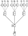
また、末端のSSの要求を効率的かつ高精度で反映させるために図31に示すようにSSの要求をそのままOLTに転送し、OLTで集中的に割当を行う方法があるが、この構成では、OLTにおける処理の負荷が著しく高くなるという問題があった。 Further, in order to reflect the request of the terminal SS efficiently and with high accuracy, as shown in FIG. 31, there is a method in which the SS request is transferred to the OLT as it is and allocation is concentrated in the OLT. There has been a problem that the processing load in the OLT becomes extremely high.
また、上述した特許文献1のものは、公衆インターネット接続サービスを広いエリアに提供しようとするものであり、端末装置の数が多い大規模なシステムであっても、制御回路に高価で高速な集積回路やCPUを要しないようにすることについてまで考慮されたものではなかった。
Further, the above-mentioned
本発明はこのような状況に鑑みてなされたものであり、端末装置の数が多い大規模なシステムであっても、制御回路に高価で高速な集積回路やCPUを要することなく、かつ割当要求を精度よく反映し、帯域の利用効率を高めることができる帯域割当方法、局側装置、加入者局装置、通信システム、および装置のプログラムを提供することを目的とする。 The present invention has been made in view of such a situation. Even in a large-scale system having a large number of terminal devices, the control circuit does not require an expensive and high-speed integrated circuit or a CPU, and an allocation request is made. It is an object of the present invention to provide a bandwidth allocation method, a station-side device, a subscriber station device, a communication system, and a program for the device that can accurately reflect the above and improve bandwidth utilization efficiency.
かかる目的を達成するために、本発明に係る帯域割当方法は、加入者局装置が所定の割り当て条件に基づいて帯域割当を定める割り当て工程と、上記割り当て工程で定められた帯域割当情報を上記加入者局装置が局側装置に送信する帯域送信工程と、局側装置が、上記加入者局装置から送信された帯域割当情報を、帯域割り当て対象である全ての加入者局装置に送信するパイプライン送信工程とを備えたことを特徴とする。 In order to achieve this object, a bandwidth allocation method according to the present invention includes an allocation step in which a subscriber station apparatus determines bandwidth allocation based on a predetermined allocation condition, and the bandwidth allocation information defined in the allocation step is added to the subscription A bandwidth transmission step for transmitting the station-side device to the station-side device, and a pipeline for the station-side device to transmit the bandwidth allocation information transmitted from the subscriber station device to all the subscriber station devices that are the target of bandwidth allocation. And a transmission step.
また、本発明に係る加入者局装置は、所定の割り当て条件に基づいて帯域割当を定める割り当て手段と、上記割り当て手段で定められた帯域割当情報を局側装置に送信する帯域送信手段と、を備えたことを特徴とする。 Further, the subscriber station apparatus according to the present invention comprises: allocation means for determining bandwidth allocation based on a predetermined allocation condition; and bandwidth transmission means for transmitting the bandwidth allocation information determined by the allocation means to the station side device. It is characterized by having.
また、本発明に係る局側装置は、複数の加入者局装置が宅内中継装置を介して接続されて用いられる局側装置であって、上記加入者局装置から送信された帯域割当情報を、帯域割り当て対象である全ての加入者局装置に送信するパイプライン送信手段を備えたことを特徴とする。 Further, the station side device according to the present invention is a station side device that is used by connecting a plurality of subscriber station devices via a home relay device, the bandwidth allocation information transmitted from the subscriber station device, It is characterized by comprising pipeline transmission means for transmitting to all the subscriber station devices that are band allocation targets.
また、本発明に係る通信システムは、上述した本発明に係る加入者局装置が宅内中継装置に無線通信で接続され、該宅内中継装置が光分岐結合器を介して、上述した本発明に係る局側装置に接続されて構成されたことを特徴とする。 Further, the communication system according to the present invention includes the above-described subscriber station apparatus according to the present invention connected to the in-house relay apparatus by wireless communication, and the in-house relay apparatus according to the above-described present invention via the optical branching coupler. It is characterized by being connected to a station side device.
また、本発明に係る加入者局装置のプログラムは、所定の割り当て条件に基づいて帯域割当を定める割り当て処理と、上記割り当て処理で定められた帯域割当情報を局側装置に送信する帯域送信処理と、を加入者局装置のコンピュータに実行させることを特徴とする。 Further, the program of the subscriber station apparatus according to the present invention includes an allocation process for determining a band allocation based on a predetermined allocation condition, and a band transmission process for transmitting the band allocation information determined by the allocation process to the station side apparatus. Are executed by the computer of the subscriber station apparatus.
また、本発明に係る局側装置のプログラムは、複数の加入者局装置が宅内中継装置を介して接続されて用いられる局側装置のプログラムであって、上記加入者局装置から送信された帯域割当情報を、帯域割り当て対象である全ての加入者局装置に送信するパイプライン送信処理を局側装置のコンピュータに実行させることを特徴とする。 Further, the station-side device program according to the present invention is a station-side device program in which a plurality of subscriber station devices are connected and used via a home relay device, and is a band transmitted from the subscriber station device. A pipeline transmission process for transmitting allocation information to all subscriber station devices that are the target of bandwidth allocation is executed by a computer of the station side device.
以上のように、本発明によれば、端末装置の数が多い大規模なシステムであっても、制御回路に高価で高速な集積回路やCPUを要することなく、かつ割当要求を精度よく反映し、帯域の利用効率を高めることができる。 As described above, according to the present invention, even in a large-scale system having a large number of terminal devices, the control request does not require an expensive and high-speed integrated circuit or CPU, and the allocation request is accurately reflected. Bandwidth utilization efficiency can be increased.
次に、本発明に係る帯域割当方法、局側装置、加入者局装置、通信システム、および装置のプログラムを適用した一実施形態について、図面を用いて詳細に説明する。 Next, an embodiment to which a band allocation method, a station side device, a subscriber station device, a communication system, and a device program according to the present invention are applied will be described in detail with reference to the drawings.
まず、本実施形態の概略について説明する。
本実施形態では、図1に示すように、加入者局装置が、所定の割り当て条件に基づいて帯域割当を定める割り当て手段と、その割り当て手段で定められた帯域割当情報を局側装置に送信する帯域送信手段と、を備える。
また、局側装置は、加入者局装置から送信された帯域割当情報を、帯域割り当て対象である全ての加入者局装置に送信するパイプライン送信手段を備える。
First, an outline of the present embodiment will be described.
In this embodiment, as shown in FIG. 1, the subscriber station apparatus transmits to the station side apparatus an allocation unit that determines bandwidth allocation based on a predetermined allocation condition, and bandwidth allocation information that is determined by the allocation unit. Band transmitting means.
The station-side device includes pipeline transmission means for transmitting the bandwidth allocation information transmitted from the subscriber station device to all the subscriber station devices that are the target of bandwidth allocation.
こうした構成により、本実施形態は、PONとWiMAXが融合したアクセスネットワークにおいて上り方向の帯域割当制御部を各加入者局(SS:Subscriber Station)に分散配備し、かつパイプライン処理を導入することにより、PON局側装置、PON宅内装置兼WiMAX基地局装置ONU−BSの処理負担を軽減し、帯域使用効率が高く、かつ帯域割当要求を割当結果に忠実に反映し、公平でスケーラビリティの高い帯域割当方法を提供することを特徴とする。 With this configuration, the present embodiment is configured by distributing the upstream bandwidth allocation control unit to each subscriber station (SS: Subscriber Station) and introducing pipeline processing in an access network in which PON and WiMAX are integrated. , PON station side device, PON in-home device and WiMAX base station device ONU-BS reduces processing load, has high bandwidth usage efficiency, faithfully reflects bandwidth allocation request in allocation results, and provides fair and highly scalable bandwidth allocation Providing a method.
次に、本実施形態の構成について説明する。
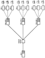
図2に本実施形態の構成を示す。本図2は、各ONU−BS装置に加入者局装置(SS)がそれぞれ3台収容される場合について機能配備を示している。
Next, the configuration of the present embodiment will be described.
FIG. 2 shows the configuration of this embodiment. FIG. 2 shows the functional deployment in the case where three subscriber station devices (SS) are accommodated in each ONU-BS device.
PONとWiMAXから構成されるアクセスネットワークの一般的な構成、方式については、背景技術として上述しているが、本実施形態は、上述した関連技術で局側装置(OLT)およびWiMAX基地局装置に配備されていた帯域割当制御部(AM;Allocation Module)を、各加入者局装置(SS1〜ONU9)に分散配備するように構成している。
このため、本実施形態では、割当結果が上り信号とともにOLTまで通知される。
The general configuration and method of an access network composed of PON and WiMAX have been described above as the background art. However, in the present embodiment, the above-described related technology is applied to the station side device (OLT) and the WiMAX base station device. The allocated bandwidth allocation control unit (AM; Allocation Module) is configured to be distributed to each subscriber station device (SS1 to ONU9).
For this reason, in this embodiment, the allocation result is notified to the OLT together with the uplink signal.
また、上り信号の待ち合わせ用バッファはSSのみに搭載することとし、OLT−BSには搭載しない。OLT−BSでは信号変換に伴う固定遅延のみが発生するように装置を構成する。OLTは、各SSで決定された割当結果を全SSに通知する機能として、NM(Notification Module)を備える。 The upstream signal waiting buffer is mounted only on the SS and not on the OLT-BS. In the OLT-BS, the apparatus is configured so that only a fixed delay accompanying signal conversion occurs. The OLT includes an NM (Notification Module) as a function for notifying all SSs of the allocation result determined in each SS.
本実施形態としての通信システムでは、図2に示すように、OLT100に、ONU−BS300が、光分岐結合器Optical Splitter200を介して接続される。また、そのONU−BS300に、SS400が無線通信により接続され、そのSS400に端末装置500が接続されて構成される。
In the communication system according to the present embodiment, as shown in FIG. 2, an ONU-
OLT100は、図3に示すように、上述したNM(パイプライン送信手段)110と、ONUとの通信制御など装置全体の制御を行う制御部120と、通信IF(インタフェース)である通信部130とを備える。
As shown in FIG. 3, the
SS400は、図4に示すように、上述したAM(割り当て手段)410と、OLTとの通信制御など装置全体の制御を行う制御部420と、通信IF(インタフェース)である通信部430とを備える。上述した帯域送信手段は、この制御部420と通信部430とにより実現される。
As shown in FIG. 4, the
各SSの帯域割当制御部(AM1〜AM9)は自装置内のコネクション毎のバッファキューの状態(待ち行列の長さ)とOLTから通知される他SSの帯域割当結果に基づき自SSの帯域割当を実行する機能を有する。各SSから送出される帯域割当結果は各コネクションの信号先頭がPONのフレームとしてOLTに到達する時刻および継続時間が含まれている。 The bandwidth allocation control unit (AM1 to AM9) of each SS allocates the bandwidth of the own SS based on the buffer queue state (queue length) for each connection in the own device and the bandwidth allocation result of the other SS notified from the OLT. It has a function to execute. The band allocation result transmitted from each SS includes the time and duration for reaching the OLT as a frame in which the signal head of each connection is PON.
AM1〜AM9は帯域割当モジュールであり、これらはOLTを介して通知される他SSの割当情報に基づきパイプライン処理によって帯域割当を実行する機能を有する。すなわちAM1〜AM9はOLTおよびONU−BSを介して、それぞれSS1〜SS9の各自のキューの状態(queue status)および前段SSのモジュールからの割当結果(allocation result)を受け取り、次段SSのモジュールに対し割当結果を送信する構成とする。また、完成した割当(completed allocation)に基づき各SSは上り信号を送出する構成とする。ONU−BSはWiMAXの上り信号をPONのフレームでカプセル化してOLTに送信する構成をとる。 AM1 to AM9 are bandwidth allocation modules, which have a function of performing bandwidth allocation by pipeline processing based on allocation information of other SSs notified via the OLT. That is, AM1 to AM9 receive the respective queue statuses (queue status) of SS1 to SS9 and the allocation result (allocation result) from the module of the previous SS via the OLT and ONU-BS, respectively, and send them to the module of the next SS. In contrast, the allocation result is transmitted. Further, each SS is configured to transmit an uplink signal based on completed allocation. The ONU-BS is configured to encapsulate the WiMAX upstream signal in a PON frame and transmit it to the OLT.
次に、本実施形態による動作について説明する。
全SSによるデータ送信が一巡する周期を、改めてService Cycle(SCと略記)と定義する。本発明では現SCの期間内に次のSCの帯域割当を実行する。
Next, the operation according to the present embodiment will be described.
The cycle in which data transmission by all SSs is completed is defined as Service Cycle (abbreviated as SC). In the present invention, bandwidth allocation of the next SC is executed within the current SC period.
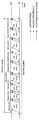
図5〜図13に、図2の構成における帯域割当の動作を示す。
まず、システム立ち上げ時にOLT、ONU−BS、SSの間に行われる時刻合わせ及び距離(伝播遅延時間)測定の結果は各ONU−BS、SSに通知されメモリに格納される。したがって各AMはその帯域割当において信号先頭のOLTへの到達時刻を計算することができる。
5 to 13 show the band allocation operation in the configuration of FIG.
First, the results of time adjustment and distance (propagation delay time) measurement performed between the OLT, ONU-BS, and SS at the time of system startup are notified to each ONU-BS and SS and stored in the memory. Therefore, each AM can calculate the arrival time at the signal head OLT in the band allocation.
また、各SSは自身の装置番号、すなわちパイプライン処理の何番目に位置するかをOLTからの通知により認識しているものとする。本実施例において帯域割当はSSのコネクション毎に行うこととする。
また、SCの合計最大帯域(Maximum of Service Cycle)および各SSの最大帯域を予め定めておき、割当時にこれを超過しないようにする。ここで各SSの最大帯域の合計は必ずしもSCの合計最大帯域以下とする必要はない。
In addition, it is assumed that each SS recognizes its own device number, that is, the position in the pipeline processing, by notification from the OLT. In this embodiment, bandwidth allocation is performed for each SS connection.
Further, the total maximum bandwidth (maximum of service cycle) of SC and the maximum bandwidth of each SS are determined in advance, and are not exceeded at the time of allocation. Here, the sum of the maximum bandwidth of each SS does not necessarily need to be equal to or less than the total maximum bandwidth of the SC.
AM1は自身のコネクションのキューの状態に基づきSS1に関するSC2の割当を行う。この時、Maximum of Service Cycleの範囲内および自身の最大帯域に収まるならばAM1は自身のキューに滞留する信号をすべて送信できるように割当を行う。AM1はこの結果をWiMAXの帯域要求フレームのフォーマット(6バイト)でONU−BSに通知する。 AM1 allocates SC2 for SS1 based on the queue status of its connection. At this time, if it is within the range of Maximum of Service Cycle and within its maximum bandwidth, AM1 performs allocation so that all signals staying in its own queue can be transmitted. AM1 notifies the ONU-BS of this result in the format of WiMAX bandwidth request frame (6 bytes).
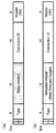
図14にWiMAXの帯域要求フレームのフレーム構成を示す。図14(a)がWiMAXの帯域要求フレームそのものであり、図14(b)は本実施形態で使用する割当結果通知用に修正されたフレームフォーマットである。ひとつのフレームで割当結果に関する情報を2バイト通知することができる。 FIG. 14 shows the frame structure of a WiMAX bandwidth request frame. FIG. 14A shows the WiMAX bandwidth request frame itself, and FIG. 14B shows a frame format modified for notification of the allocation result used in this embodiment. Information about the allocation result can be notified by 2 bytes in one frame.
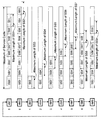
EPONの上り方向の割当結果(GATEフレーム)は、図15(a)に示すように、ひとつのONUあたり6バイトを必要とする。したがって、各SSは自装置の上り方向割当結果をPONの割当結果の形で表現し、これを上記の割当結果通知用フレーム3個分の中に収めてONU−BSに情報を送る。これらの割当結果フレームにはOLTへの信号到達時刻および信号継続時間が含まれている。OLTへの到達時刻は立ち上げ時に通知されたOLT〜SS1の伝播遅延時間から計算される。ONU−BSは直ちにこれをPONのREPORTフレームとしてカプセル化しOLTに送信する。 As shown in FIG. 15A, the EPON uplink allocation result (GATE frame) requires 6 bytes per ONU. Accordingly, each SS expresses the uplink allocation result of its own device in the form of the PON allocation result, and sends this information to the ONU-BS in the above three allocation result notification frames. These allocation result frames include a signal arrival time and a signal duration time to the OLT. The arrival time to the OLT is calculated from the propagation delay time of the OLT to SS1 notified at the start-up. The ONU-BS immediately encapsulates it as a PON REPORT frame and sends it to the OLT.
REPORTフレームのPDUは最大16バイトでありWiMAXの帯域要求フレーム(6バイト)を収容することができる。図16にPONのREPORTフレームを示す。図16(a)がPONの帯域要求フレームそのものであり、図16(b)は本実施形態で使用する割当結果通知用に修正されたフレームフォーマットである。 The PDU of the REPORT frame has a maximum of 16 bytes and can accommodate a WiMAX bandwidth request frame (6 bytes). FIG. 16 shows a PON REPORT frame. FIG. 16A shows the PON bandwidth request frame itself, and FIG. 16B shows a frame format modified for notification of the allocation result used in this embodiment.
OLTはSS1の割当結果を直ちに下り信号としてONU−BSを通じて全SSに通知する。この通知信号をNotificationと呼ぶこととする。ONU−BSは、このカプセル化された通知信号をカプセル解除して上述したWiMAXのフレーム構成とし、各SSに送信する。図15(b)が、図15(a)に示すPONのGATEフレームを修正したNotificationフレームである。図5のAllocation(SS1)はここまでの動作が行われる時間を示している。
The OLT immediately notifies the
次にSS2のAM2はOLTからの通知情報(すなわち1つ前に帯域割当を行ったSS1による帯域割当情報)および自身のキューの状態に基づき、SS2に関するSC2の割当を行う。OLTからの情報はONU1の信号の先頭がOLTに到着する時刻と信号の継続時間を含んでいるため、SS2はそれと衝突しないように信号送出開始時刻を決める。この時、SS2は立ち上げの際に通知されたOLT〜SS2間の伝播遅延時間を用いて時刻の計算を行う。 Next, the AM2 of the SS2 allocates the SC2 regarding the SS2 based on the notification information from the OLT (that is, the band allocation information by the SS1 that allocated the previous band) and the status of its own queue. Since the information from the OLT includes the time at which the head of the ONU1 signal arrives at the OLT and the duration of the signal, SS2 determines the signal transmission start time so as not to collide with it. At this time, SS2 calculates time using the propagation delay time between OLT and SS2 notified at the time of startup.
AM2は割当結果をONU−BSを介してOLTに通知しその結果は下り信号で再び全SSに通知される。図6のAllocation(SS2)はここまでの動作が行われる時間を示している。
The
以下、同様にしてAM3〜AM9はOLTおよびONU−BSを介して前段AMから渡された結果と自身のキューの状態に基づき各SSに関するSC2の割当を行う。この時、各SSではあらかじめ設定された最大帯域及びSCの合計帯域を超過しないように割当を行う。AM9においてSC2の割当は完了し、割当結果はAM9からOLTに渡され、再度全SSに通知される。 Thereafter, similarly, AM3 to AM9 allocate SC2 for each SS based on the result passed from the preceding AM through the OLT and ONU-BS and the status of its own queue. At this time, each SS performs allocation so as not to exceed the preset maximum bandwidth and the total bandwidth of the SC. The allocation of SC2 is completed at AM9, and the allocation result is passed from AM9 to the OLT and notified to all SSs again.
同様にSC3の割当はAM2→AM3→AM4→・・・→AM9→AM1の順序で行い結果は全SSが共有する。また、SC4の割当はAM3→AM4→AM5→・・・→AM9→AM1→AM2の順序で行い結果は全ONUが共有する。
以下同様にして割当を行いSC10の割当はAM9→AM1→AM2→・・・→AM8の順序で行う。
Similarly, SC3 is assigned in the order of AM2, AM3, AM4,..., AM9, and AM1, and the results are shared by all SSs. SC4 is assigned in the order of AM3->AM4->AM5->...->AM9->AM1-> AM2, and the result is shared by all ONUs.
Thereafter, the allocation is performed in the same manner, and the allocation of SC10 is performed in the order of AM9 → AM1 → AM2 →.
割当の開始モジュールをSCによって循環的に変化させるため、SSからのデータ送出順序も循環的に変化させる。すなわちSC2はSS1→SS2→・・・→SS9、SC3はSS2→SS3→・・・→SS9→SS1、SC4はSS3→SS4→・・・→SS9→SS1→SS2の順序でデータ送出を行う。以下のSCも同様である。 Since the allocation start module is cyclically changed by the SC, the data transmission order from the SS is also cyclically changed. That is, SC2 sends data in the order SS1 → SS2 →... → SS9, SC3 sends SS2 → SS3 →... → SS9 → SS1, and SC4 sends data in the order SS3 → SS4 →. The same applies to the following SCs.
各SSからの割当結果はPONの上りデータにpiggy backされるのでデータと同じ順序でSSからの割当結果が到着する。割当の開始モジュールを循環的に変化させることによりSS間の公平性が保たれる。 Since the allocation result from each SS is piggybacked to the upstream data of the PON, the allocation result from the SS arrives in the same order as the data. By changing the allocation start module cyclically, fairness among the SSs is maintained.
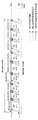
図17〜図20は、SC2からSC4までの割当の動作例を示したものである。図17および図18では、全SSの帯域要求が合計最大帯域を下回るため全てのSSの割当要求が結果に反映される。図19では合計最大帯域の制限からSS2の割当が制限されている様子を示している。図20では同様にSS3が割当の制限を受けている様子を示す。
図21、図22は、SSからの割当結果通知およびOLTによる全SSへの一斉通知の様子を示している。
FIGS. 17 to 20 show an example of the operation of allocation from SC2 to SC4. In FIG. 17 and FIG. 18, since the bandwidth request for all SSs is below the total maximum bandwidth, all SS allocation requests are reflected in the results. FIG. 19 shows a state in which the allocation of SS2 is restricted due to the restriction of the total maximum bandwidth. FIG. 20 similarly shows that SS3 is subject to allocation restrictions.
FIG. 21 and FIG. 22 show the assignment result notification from the SS and the simultaneous notification to all the SSs by OLT.
このように、SCの中で帯域割当を最初に定めるSSのAMは、次のSCにおける帯域割当を行う際、自装置における送信待ちのキューを、そのSSについて予め設定された最大帯域の範囲内で送信するように帯域割当を定め、その定めた帯域割当情報をReportとしてOLT100に通知する。
In this way, when the SS of the SS that first determines the bandwidth allocation in the SC, when performing the bandwidth allocation in the next SC, the transmission waiting queue in the own device is set within the range of the maximum bandwidth preset for the SS. Then, the bandwidth allocation is determined so as to be transmitted, and the determined bandwidth allocation information is reported to the
また、SCの中で帯域割当を定める順序が最初でないSSのAMは、次のSCにおける帯域割当を行う際、OLT100からの通知情報(すなわち1つ前に帯域割当を行ったSSによる帯域割当情報)を用いて、まず、自装置における送信待ちのキューをそのSSについて予め設定された最大帯域の範囲内で割り当て可能な場合、そのように帯域割当を行う。
また、自装置における送信待ちのキューがそのSSについて予め設定された最大帯域の範囲内では割り当て不可能な場合、割り当て可能な分だけの帯域割当を行う。
In addition, when an AM of an SS whose band allocation is not first in the SC is allocated, the notification information from the OLT 100 (that is, the band allocation information by the SS that performed the previous band allocation) when performing the band allocation in the next SC. First, when a queue waiting for transmission in the own apparatus can be allocated within the range of the maximum bandwidth set in advance for the SS, bandwidth allocation is performed in that way.
Further, if the queue waiting for transmission in the own apparatus cannot be allocated within the range of the maximum bandwidth set in advance for the SS, bandwidth allocation is performed as much as possible.
以上のように、上述した実施形態によれば以下の効果が得られる。
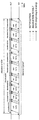
まず、OLTおよび各ONU−BSにおいて全ての割当要求が到着してから割当を行う従来例に比べて、本発明の帯域割当方法は上りデータ受信時間を利用して逐次的に割当処理を進めるため、帯域を無駄にすることがない。このことは従来例のタイミングチャート図23と本発明のタイミングチャートである図5〜図13とを比較すれば明瞭である。
As described above, according to the above-described embodiment, the following effects can be obtained.
First, compared to the conventional example in which allocation is performed after all allocation requests arrive at the OLT and each ONU-BS, the bandwidth allocation method of the present invention sequentially proceeds with allocation processing using the uplink data reception time. , Never waste bandwidth. This can be clearly seen by comparing the conventional timing chart of FIG. 23 with the timing charts of FIGS. 5 to 13 of the present invention.
しかも帯域の割当順序を循環的に変化させることによりONU間の公平性が確保される。また、分散処理によって処理時間に余裕が生じるためにSSやONUの数が増えても制御部の負荷が著しく増大することはない。安価な回路素子またはCPUで制御部を構成することができシステムのコストを削減できる。また、末端のSSが直接割当を行うため精度のよい割当が可能となる。 Moreover, fairness among ONUs is ensured by cyclically changing the bandwidth allocation order. Further, since the processing time is provided by the distributed processing, the load on the control unit does not increase significantly even if the number of SSs and ONUs increases. The control unit can be configured with an inexpensive circuit element or CPU, and the cost of the system can be reduced. In addition, since the terminal SS performs direct allocation, accurate allocation is possible.
このように、本実施形態によれば、末端のSS間の上り帯域の公平性維持、割当要求の精度のよい反映、帯域の利用効率の向上、かつ高いスケーラビリティを実現する帯域割当方法を提供することができる。 As described above, according to the present embodiment, a bandwidth allocation method is provided that maintains the fairness of the upstream bandwidth between the terminal SSs, accurately reflects the allocation request, improves the efficiency of bandwidth utilization, and achieves high scalability. be able to.
なお、上述した各実施形態は本発明の好適な実施形態であり、本発明はこれに限定されることなく、本発明の技術的思想に基づいて種々変形して実施することが可能である。
例えば、上述した実施形態では9台のSSに対して割当を行う例を示したが、これを一般的にN台(Nは自然数)のSSに拡張しても、本実施形態を同様に適用することができる。その場合はN台のAMが仮想的にリング状に接続されパイプライン処理が行われることになる。
Each of the above-described embodiments is a preferred embodiment of the present invention, and the present invention is not limited to this, and various modifications can be made based on the technical idea of the present invention.
For example, in the above-described embodiment, an example in which allocation is performed for nine SSs has been shown. However, even if this is expanded to N (N is a natural number) SS, the present embodiment is similarly applied. can do. In this case, N AMs are virtually connected in a ring shape and pipeline processing is performed.
また、上述した実施形態ではプライオリティに基づく割当については記していないが、SSの各コネクションに優先度を付与し、この情報を全SSが共有することによってプライオリティに基づく割当が可能となる。
このように、SSの各コネクションへの帯域割当に優先度が関連付けられる場合、SCの中で帯域割当を定める順序が最初でないSSのAMが帯域割当を行う際、自装置における送信待ちのキューがそのSSについて予め設定された最大帯域の範囲内では割り当て不可能であれば、優先度のより低い加入者局装置への割り当てデータよりも、優先度のより高い加入者局装置への割り当てを優先させるように帯域割当を変更する。
In the above-described embodiment, priority-based allocation is not described, but priority is assigned to each connection of the SS, and all SSs share this information, so that allocation based on priority is possible.
In this way, when the priority is associated with the bandwidth allocation to each SS connection, when the SS AM whose order of determining the bandwidth allocation is not the first in the SC performs the bandwidth allocation, there is a transmission waiting queue in the own device. If allocation is impossible within the range of the maximum bandwidth set in advance for the SS, priority is given to allocation to a subscriber station device having a higher priority than to allocation data to a subscriber station device having a lower priority. Change the bandwidth allocation to
また、上述した実施形態ではEPONを用いて説明したが、本方式をGPON、BPONなど他のPON方式に適用することも可能である。 In the above-described embodiment, EPON has been described. However, this method can be applied to other PON methods such as GPON and BPON.
このように、上述した実施形態では、N台のSSを有するPONとWiMAXの融合ネットワークにおいて上り帯域割当において、各SSに搭載されるN個のアロケーションモジュールによって帯域割当のパイプライン処理を行う方法うぃお提供する。
また、各SSがONU−BSおよびOLTを介して他SSの割当結果を認識する方法、割当順序を循環的に変化させる方法を提供する。
また、1つ先のサービスサイクルの割当処理を現サービスサイクル内に分散して行う方法を提供する。
また、サービスサイクル毎の帯域上限、SS毎の帯域上限を設定する方法を提供する。
また、各SSの割当結果をPONの割当要求フォーマット(REPORT)を使用してPON上を転送し、OLTに通知する方法を提供する。
また、割当結果をPONの割当許可フォーマット(GATE)を使用してPON上を転送し、さらに全SSに通知する方法を提供する。
さらに、上り方向の待ち合わせバッファをSSのみに搭載する構成を提供する。
As described above, in the above-described embodiment, in the upstream bandwidth allocation in the PON and WiMAX fusion network having N SSs, the bandwidth allocation pipeline processing is performed by the N allocation modules installed in each SS. Provide.
In addition, a method is provided in which each SS recognizes the assignment result of another SS via the ONU-BS and OLT, and a method of cyclically changing the assignment order.
In addition, a method is provided in which the allocation process of the next service cycle is distributed in the current service cycle.
In addition, a method for setting a bandwidth upper limit for each service cycle and a bandwidth upper limit for each SS is provided.
Also, a method is provided in which the allocation result of each SS is transferred on the PON using the PON allocation request format (REPORT) and notified to the OLT.
Also, a method is provided in which the allocation result is transferred on the PON using the PON allocation permission format (GATE), and is further notified to all SSs.
In addition, a configuration is provided in which an uplink waiting buffer is mounted only on the SS.
また、上述した各実施形態としての通信システム、局側装置、加入者局装置を実現するための処理手順をプログラムとして記録媒体に記録することにより、本発明の各実施形態による上述した各機能を、その記録媒体から供給されるプログラムによって、システムを構成するコンピュータのCPUに処理を行わせて実現させることができる。
この場合、上記の記録媒体により、あるいはネットワークを介して外部の記録媒体から、プログラムを含む情報群を出力装置に供給される場合でも本発明は適用されるものである。
すなわち、記録媒体から読み出されたプログラムコード自体が本発明の新規な機能を実現することになり、そのプログラムコードを記憶した記録媒体および該記録媒体から読み出された信号は本発明を構成することになる。
この記録媒体としては、例えばフレキシブルディスク、ハードディスク、光ディスク、光磁気ディスク、CD−ROM、CD−R、CD−RW、DVD−ROM、DVD−RAM、DVD−RW、DVD+RW、磁気テープ、不揮発性のメモリーカード、ROM等を用いてよい。
Further, by recording the processing procedure for realizing the communication system, the station side apparatus, and the subscriber station apparatus as the above-described embodiments on a recording medium as a program, the above-described functions according to the respective embodiments of the present invention are achieved. The program supplied from the recording medium can be realized by causing the CPU of a computer constituting the system to perform processing.
In this case, the present invention can be applied even when an information group including a program is supplied to the output device from the above recording medium or from an external recording medium via a network.
That is, the program code itself read from the recording medium realizes the novel function of the present invention, and the recording medium storing the program code and the signal read from the recording medium constitute the present invention. It will be.
As this recording medium, for example, flexible disk, hard disk, optical disk, magneto-optical disk, CD-ROM, CD-R, CD-RW, DVD-ROM, DVD-RAM, DVD-RW, DVD + RW, magnetic tape, non-volatile A memory card, ROM or the like may be used.
この本発明に係るプログラムによれば、当該プログラムによって制御される各装置に、上述した各実施形態における各機能を実現させることができる。 According to the program according to the present invention, each device in the above-described embodiments can be realized in each device controlled by the program.
100 OLT(局側装置の一例)
110 NM(パイプライン送信手段の一例)
300 ONU−BS(宅内中継装置の一例)
400 SS(加入者局装置の一例)
410 AM(割り当て手段の一例)
100 OLT (an example of a station side device)
110 NM (an example of pipeline transmission means)
300 ONU-BS (an example of a home relay device)
400 SS (an example of a subscriber station device)
410 AM (an example of allocation means)
Claims (26)
前記割り当て工程で定められた帯域割当情報を前記加入者局装置が局側装置に送信する帯域送信工程と、
局側装置が、前記加入者局装置から送信された帯域割当情報を、帯域割り当て対象である全ての加入者局装置に送信するパイプライン送信工程とを備えたことを特徴とする帯域割当方法。 An allocation step in which the subscriber station apparatus determines bandwidth allocation based on predetermined allocation conditions;
A bandwidth transmission step in which the subscriber station device transmits the bandwidth allocation information determined in the allocation step to the station side device;
A bandwidth allocation method comprising: a pipeline transmission step in which the station side device transmits the bandwidth allocation information transmitted from the subscriber station device to all the subscriber station devices that are the target of bandwidth allocation.
帯域割当対象である全ての加入者局装置によるデータ送信が一巡する一巡周期の間に、次の一巡周期での帯域割当が決定されることを特徴とする請求項1記載の帯域割当方法。 The subscriber station apparatus transmits the band allocation information together with transmission data in the allocated band to the station side apparatus,
2. The bandwidth allocation method according to claim 1, wherein bandwidth allocation in the next round cycle is determined during a round cycle in which data transmission by all subscriber station devices that are bandwidth allocation cycles.
自装置における送信待ちのキューを該装置について予め設定された最大帯域の範囲内で割り当て可能な場合、当該割り当てを行い、
自装置における送信待ちのキューが該装置について予め設定された最大帯域の範囲内では割り当て不可能な場合、割り当て可能な分だけの割り当てを行うことを特徴とする請求項2または3記載の帯域割当方法。 The subscriber station apparatus that is not first in the order of determining the bandwidth allocation by the allocation step in the round cycle uses the bandwidth allocation information transmitted by the pipeline transmission step in the allocation step,
When the queue waiting for transmission in the own apparatus can be allocated within the range of the maximum bandwidth set in advance for the apparatus, the allocation is performed,
4. The bandwidth allocation according to claim 2, wherein when a queue waiting for transmission in the own device cannot be allocated within a range of a maximum bandwidth set in advance for the device, allocation is performed as much as possible. Method.
前記最初でない加入者局装置は、前記割り当て不可能な場合、優先度のより低い加入者局装置への割り当てデータよりも、優先度のより高い加入者局装置への割り当てを優先させるように帯域割当を変更することを特徴とする請求項5記載の帯域割当方法。 For each subscriber station device that is a bandwidth allocation target, a priority is associated with the allocation,
When the allocation is impossible, the non-first subscriber station apparatus has a bandwidth so that the allocation to the subscriber station apparatus having a higher priority is given priority over the allocation data to the subscriber station apparatus having a lower priority. 6. The bandwidth allocation method according to claim 5, wherein the allocation is changed.
前記割り当て手段で定められた帯域割当情報を局側装置に送信する帯域送信手段と、を備えたことを特徴とする加入者局装置。 Allocation means for determining bandwidth allocation based on predetermined allocation conditions;
A subscriber station apparatus comprising: band transmitting means for transmitting band allocation information determined by the allocating means to a station side apparatus.
前記加入者局装置が接続された通信システムにおける帯域割当対象である全ての加入者局装置によるデータ送信が一巡する一巡周期の間に、該通信システムにおける次の一巡周期での帯域割当が決定されることを特徴とする請求項8記載の加入者局装置。 The band transmitting means transmits the band allocation information together with transmission data in the allocated band to the station side device,
Bandwidth allocation in the next round cycle in the communication system is determined during a round cycle in which data transmission by all the subscriber station devices that are band allocation targets in the communication system to which the subscriber station device is connected makes a round. The subscriber station apparatus according to claim 8, wherein:
自装置における送信待ちのキューを該装置について予め設定された最大帯域の範囲内で割り当て可能な場合、当該割り当てを行い、
自装置における送信待ちのキューが該装置について予め設定された最大帯域の範囲内では割り当て不可能な場合、割り当て可能な分だけの割り当てを行うことを特徴とする請求項9または10記載の加入者局装置。 The allocating means uses the band allocation information transmitted from the station side device when the own device is not a subscriber station device that first determines the band allocation in the round cycle,
When the queue waiting for transmission in the own apparatus can be allocated within the range of the maximum bandwidth set in advance for the apparatus, the allocation is performed,
11. The subscriber according to claim 9 or 10, wherein when the queue waiting for transmission in the own apparatus cannot be allocated within a range of a maximum bandwidth set in advance for the apparatus, allocation is performed as much as possible. Station equipment.
前記割り当て手段は、自装置が前記最初でない加入者局装置であり、前記割り当て不可能な場合、優先度のより低い加入者局装置への割り当てデータよりも、優先度のより高い加入者局装置への割り当てを優先させるように帯域割当を変更することを特徴とする請求項12記載の加入者局装置。 For each subscriber station device that is a bandwidth allocation target, a priority is associated with the allocation,
The assigning means is a subscriber station apparatus having a higher priority than assignment data to a subscriber station apparatus having a lower priority when the own apparatus is the first non-first subscriber station apparatus and the assignment is impossible. 13. The subscriber station apparatus according to claim 12, wherein bandwidth allocation is changed so that allocation to the network is prioritized.
前記加入者局装置から送信された帯域割当情報を、帯域割り当て対象である全ての加入者局装置に送信するパイプライン送信手段を備えたことを特徴とする局側装置。 A station-side device used by connecting a plurality of subscriber station devices via a home relay device,
A station-side apparatus comprising pipeline transmission means for transmitting band allocation information transmitted from the subscriber station apparatus to all subscriber station apparatuses that are band allocation targets.
帯域割当対象である全ての加入者局装置によるデータ送信が一巡する一巡周期の間に、次の一巡周期での帯域割当が決定されることを特徴とする請求項14記載の局側装置。 The subscriber station device transmits the band allocation information to the station side device when transmitting data in the allocated band,
15. The station side device according to claim 14, wherein bandwidth allocation in the next round cycle is determined during a round cycle in which data transmission by all subscriber station devices that are bandwidth allocation cycles.
前記割り当て処理で定められた帯域割当情報を局側装置に送信する帯域送信処理と、を加入者局装置のコンピュータに実行させることを特徴とする加入者局装置のプログラム。 An allocation process for determining bandwidth allocation based on predetermined allocation conditions;
A program for a subscriber station apparatus, which causes a computer of the subscriber station apparatus to execute a band transmission process for transmitting the band allocation information determined in the allocation process to the station side apparatus.
前記加入者局装置が接続された通信システムにおける帯域割当対象である全ての加入者局装置によるデータ送信が一巡する一巡周期の間に、該通信システムにおける次の一巡周期での帯域割当が決定されることを特徴とする請求項18記載の加入者局装置のプログラム。 In the band transmission process, the band allocation information is transmitted to the station side device together with transmission data in the allocated band,
Bandwidth allocation in the next round cycle in the communication system is determined during a round cycle in which data transmission by all the subscriber station devices that are band allocation targets in the communication system to which the subscriber station device is connected makes a round. 19. The subscriber station apparatus program according to claim 18, wherein the program is a subscriber station apparatus.
自装置における送信待ちのキューを該装置について予め設定された最大帯域の範囲内で割り当て可能な場合、当該割り当てを行い、
自装置における送信待ちのキューが該装置について予め設定された最大帯域の範囲内では割り当て不可能な場合、割り当て可能な分だけの割り当てを行うことを特徴とする請求項19または20記載の加入者局装置のプログラム。 In the allocation process, when the own device is not a subscriber station device that first determines bandwidth allocation in the round cycle, using the bandwidth allocation information transmitted from the station side device,
When the queue waiting for transmission in the own apparatus can be allocated within the range of the maximum bandwidth set in advance for the apparatus, the allocation is performed,
21. The subscriber according to claim 19 or 20, wherein when the queue waiting for transmission in the own apparatus cannot be allocated within a range of a maximum bandwidth set in advance for the apparatus, allocation is performed as much as possible. Station device program.
前記割り当て処理では、自装置が前記最初でない加入者局装置であり、前記割り当て不可能な場合、優先度のより低い加入者局装置への割り当てデータよりも、優先度のより高い加入者局装置への割り当てを優先させるように帯域割当を変更することを特徴とする請求項22記載の加入者局装置のプログラム。 For each subscriber station device that is a bandwidth allocation target, a priority is associated with the allocation,
In the assignment process, if the own apparatus is not the first subscriber station apparatus and the assignment is impossible, the subscriber station apparatus having a higher priority than the assignment data to the subscriber station apparatus having a lower priority. 23. The program of a subscriber station apparatus according to claim 22, wherein the bandwidth allocation is changed so that the allocation to the network is prioritized.
前記加入者局装置から送信された帯域割当情報を、帯域割り当て対象である全ての加入者局装置に送信するパイプライン送信処理を局側装置のコンピュータに実行させることを特徴とする局側装置のプログラム。 A program of a station side device used by connecting a plurality of subscriber station devices via a home relay device,
A station-side apparatus that causes a computer of a station-side apparatus to execute pipeline transmission processing for transmitting band allocation information transmitted from the subscriber station apparatus to all subscriber station apparatuses that are band allocation targets. program.
帯域割当対象である全ての加入者局装置によるデータ送信が一巡する一巡周期の間に、次の一巡周期での帯域割当が決定されることを特徴とする請求項24記載の局側装置のプログラム。 The subscriber station device transmits the band allocation information to the station side device when transmitting data in the allocated band,
25. The program for a station-side device according to claim 24, wherein bandwidth allocation in the next round cycle is determined during a round cycle in which data transmission by all subscriber station devices that are bandwidth allocation cycles. .
Priority Applications (5)
| Application Number | Priority Date | Filing Date | Title |
|---|---|---|---|
| JP2008041027A JP5109710B2 (en) | 2008-02-22 | 2008-02-22 | Band allocation method, station side apparatus, subscriber station apparatus, communication system, and apparatus program |
| CA002653250A CA2653250A1 (en) | 2008-02-22 | 2009-02-09 | Bandwith allocation method, optical line terminator, subscriber station, communication system, and recording medium recording program of device |
| EP09002367A EP2093904A1 (en) | 2008-02-22 | 2009-02-19 | Bandwidth allocation method, optical line terminator, subscriber station, communication system, and recording medium program of device |
| US12/389,690 US8204380B2 (en) | 2008-02-22 | 2009-02-20 | Bandwidth allocation method, optical line terminator, subscriber station, communication system, and recording medium recording program of device |
| CN200910118108XA CN101515894B (en) | 2008-02-22 | 2009-02-23 | Bandwidth allocation method, optical line terminator, subscriber station and communication system |
Applications Claiming Priority (1)
| Application Number | Priority Date | Filing Date | Title |
|---|---|---|---|
| JP2008041027A JP5109710B2 (en) | 2008-02-22 | 2008-02-22 | Band allocation method, station side apparatus, subscriber station apparatus, communication system, and apparatus program |
Publications (2)
| Publication Number | Publication Date |
|---|---|
| JP2009200876A true JP2009200876A (en) | 2009-09-03 |
| JP5109710B2 JP5109710B2 (en) | 2012-12-26 |
Family
ID=40651339
Family Applications (1)
| Application Number | Title | Priority Date | Filing Date |
|---|---|---|---|
| JP2008041027A Expired - Fee Related JP5109710B2 (en) | 2008-02-22 | 2008-02-22 | Band allocation method, station side apparatus, subscriber station apparatus, communication system, and apparatus program |
Country Status (5)
| Country | Link |
|---|---|
| US (1) | US8204380B2 (en) |
| EP (1) | EP2093904A1 (en) |
| JP (1) | JP5109710B2 (en) |
| CN (1) | CN101515894B (en) |
| CA (1) | CA2653250A1 (en) |
Cited By (3)
| Publication number | Priority date | Publication date | Assignee | Title |
|---|---|---|---|---|
| JP2009200875A (en) * | 2008-02-22 | 2009-09-03 | Nec Corp | Band allocation method, station-side device, home device, communication system, and program of device |
| JP2016115959A (en) * | 2014-12-11 | 2016-06-23 | 日本電信電話株式会社 | Optical wireless communications system and traffic control method of the same |
| JP2019535170A (en) * | 2016-09-15 | 2019-12-05 | 華為技術有限公司Huawei Technologies Co.,Ltd. | Integrated mobile and TDM-PON uplink MAC scheduling for mobile fronthaul |
Families Citing this family (8)
| Publication number | Priority date | Publication date | Assignee | Title |
|---|---|---|---|---|
| CN102118659B (en) * | 2009-12-30 | 2015-01-28 | 中兴通讯股份有限公司 | Method and system for saving energy in passive optical network |
| FR2958481A1 (en) * | 2010-03-30 | 2011-10-07 | France Telecom | METHOD FOR PROCESSING A REQUEST FOR TRANSMISSION OF A RADIO SIGNAL IN A ROF SYSTEM |
| CN104660327B (en) * | 2015-03-04 | 2017-11-10 | 太仓市同维电子有限公司 | A kind of method of raising OLT utilization rates |
| KR102032363B1 (en) * | 2015-03-17 | 2019-10-16 | 한국전자통신연구원 | Optical network unit for Low latency packet transmission in time division multiplexing passive optical network, Method of operating thereof, and Apparatus for controlling optical network unit |
| CN108027723B (en) * | 2016-02-24 | 2021-02-09 | 华为技术有限公司 | Optical line terminal and method for upgrading master and slave equipment thereof |
| CN110870259B (en) * | 2017-07-19 | 2022-04-01 | 日本电信电话株式会社 | Virtual subscriber line terminal station device and control method of virtual subscriber line terminal station device |
| WO2019235564A1 (en) * | 2018-06-06 | 2019-12-12 | 日本電信電話株式会社 | Optical line terminal and band allocation method |
| CN116939405A (en) * | 2022-03-29 | 2023-10-24 | 中兴通讯股份有限公司 | Bandwidth allocation method, bandwidth allocation device, storage medium, and program product |
Citations (4)
| Publication number | Priority date | Publication date | Assignee | Title |
|---|---|---|---|---|
| JP2001156824A (en) * | 1999-11-29 | 2001-06-08 | Matsushita Electric Ind Co Ltd | Subscriber system network device and repeater station |
| JP2008072714A (en) * | 2006-09-12 | 2008-03-27 | Nec Lab America Inc | System and method for providing wireless communication over passive optical network (pon) |
| JP2009135681A (en) * | 2007-11-29 | 2009-06-18 | Mitsubishi Electric Corp | Communication system and media converter |
| JP2009200875A (en) * | 2008-02-22 | 2009-09-03 | Nec Corp | Band allocation method, station-side device, home device, communication system, and program of device |
Family Cites Families (9)
| Publication number | Priority date | Publication date | Assignee | Title |
|---|---|---|---|---|
| CN1152489C (en) * | 2001-05-09 | 2004-06-02 | 华为技术有限公司 | Implementation of dynamic bandwidth distribution of passive optical network in asynchronus transfer mode |
| KR100450771B1 (en) * | 2002-11-04 | 2004-10-01 | 한국전자통신연구원 | Method for controlling upstream data of Ethernet PON and apparatus thereof |
| KR100506209B1 (en) * | 2003-06-16 | 2005-08-05 | 삼성전자주식회사 | Dynamic bandwidth allocation method considering multiple servics for ethernet passive optical network |
| JP2005064783A (en) | 2003-08-11 | 2005-03-10 | Nec Corp | Public internet connection service system and access line connection device |
| US7362704B2 (en) * | 2003-09-15 | 2008-04-22 | Teknovus, Inc. | Method and apparatus for dynamically allocating upstream bandwidth in passive optical networks |
| CN1326340C (en) * | 2003-10-21 | 2007-07-11 | 华为技术有限公司 | Passive optical network dynamic bandwide distributing apparatus and method |
| US7564852B2 (en) * | 2005-07-20 | 2009-07-21 | Cortina Systems, Inc. | Intelligent bandwidth allocation for ethernet passive optical networks |
| JP4853821B2 (en) * | 2005-11-17 | 2012-01-11 | 日本電気株式会社 | BAND ALLOCATION DEVICE, BAND ALLOCATION METHOD, AND BAND ALLOCATION PROGRAM FOR STATION |
| JP5084197B2 (en) | 2006-08-10 | 2012-11-28 | 株式会社ソニー・コンピュータエンタテインメント | Processor node system and processor node cluster system |
-
2008
- 2008-02-22 JP JP2008041027A patent/JP5109710B2/en not_active Expired - Fee Related
-
2009
- 2009-02-09 CA CA002653250A patent/CA2653250A1/en not_active Abandoned
- 2009-02-19 EP EP09002367A patent/EP2093904A1/en not_active Withdrawn
- 2009-02-20 US US12/389,690 patent/US8204380B2/en not_active Expired - Fee Related
- 2009-02-23 CN CN200910118108XA patent/CN101515894B/en not_active Expired - Fee Related
Patent Citations (4)
| Publication number | Priority date | Publication date | Assignee | Title |
|---|---|---|---|---|
| JP2001156824A (en) * | 1999-11-29 | 2001-06-08 | Matsushita Electric Ind Co Ltd | Subscriber system network device and repeater station |
| JP2008072714A (en) * | 2006-09-12 | 2008-03-27 | Nec Lab America Inc | System and method for providing wireless communication over passive optical network (pon) |
| JP2009135681A (en) * | 2007-11-29 | 2009-06-18 | Mitsubishi Electric Corp | Communication system and media converter |
| JP2009200875A (en) * | 2008-02-22 | 2009-09-03 | Nec Corp | Band allocation method, station-side device, home device, communication system, and program of device |
Cited By (3)
| Publication number | Priority date | Publication date | Assignee | Title |
|---|---|---|---|---|
| JP2009200875A (en) * | 2008-02-22 | 2009-09-03 | Nec Corp | Band allocation method, station-side device, home device, communication system, and program of device |
| JP2016115959A (en) * | 2014-12-11 | 2016-06-23 | 日本電信電話株式会社 | Optical wireless communications system and traffic control method of the same |
| JP2019535170A (en) * | 2016-09-15 | 2019-12-05 | 華為技術有限公司Huawei Technologies Co.,Ltd. | Integrated mobile and TDM-PON uplink MAC scheduling for mobile fronthaul |
Also Published As
| Publication number | Publication date |
|---|---|
| CA2653250A1 (en) | 2009-08-22 |
| JP5109710B2 (en) | 2012-12-26 |
| CN101515894A (en) | 2009-08-26 |
| US20090214206A1 (en) | 2009-08-27 |
| US8204380B2 (en) | 2012-06-19 |
| CN101515894B (en) | 2013-07-10 |
| EP2093904A1 (en) | 2009-08-26 |
Similar Documents
| Publication | Publication Date | Title |
|---|---|---|
| JP5109710B2 (en) | Band allocation method, station side apparatus, subscriber station apparatus, communication system, and apparatus program | |
| JP4879327B2 (en) | Communication device, slave station device, and bandwidth allocation method | |
| EP3443693B1 (en) | Channel bonding in multiple-wavelength passive optical networks (pons) | |
| JP6841919B2 (en) | Data communication system, optical network unit, and baseband device | |
| JP2011082908A (en) | Intra-station device, optical communication system, band allocation method, and device program | |
| CN113973239B (en) | Method, device, optical network unit, optical line terminal and medium for communication | |
| CN108370270A (en) | Distribution method, device and the passive optical network of dynamic bandwidth | |
| JP5050914B2 (en) | Bandwidth allocation method, station side device, in-home device, communication system, and device program | |
| JP6804695B1 (en) | Optical communication device and resource management method | |
| EP4040746A1 (en) | Passive optical network-based communication method, related device, and system | |
| Erkan et al. | Dynamic and fair resource allocation in a distributed ring-based WDM-PON architectures | |
| JP5327804B2 (en) | Optical communication system and optical communication method | |
| JP5414629B2 (en) | COMMUNICATION SYSTEM, SUBSCRIBER TERMINAL DEVICE AND COMMUNICATION METHOD | |
| JP5822689B2 (en) | PON system, station side optical terminator, and bandwidth control method | |
| JP5290917B2 (en) | Optical communication system and optical communication method | |
| JP6676496B2 (en) | Optical network unit, optical network unit, and computer program | |
| JP2009278165A (en) | Optical communication system | |
| JP6992596B2 (en) | Station-side equipment, subscriber-side equipment, optical access network and bandwidth allocation method | |
| JP6554084B2 (en) | Optical signal transmission method and optical concentrating network system | |
| JP6667428B2 (en) | Optical transmission device, optical concentrator network system, and data transmission instruction method | |
| JP5466321B2 (en) | Optical communication system and optical communication method | |
| Radivojević et al. | Multichannel EPON | |
| JP5507393B2 (en) | Communication device, one-to-many communication system and uplink timing control method | |
| KR20180115902A (en) | A method for determining at least one wavelength to use when transmitting a data message based on a scheduled time of use of a plurality of wavelengths used in an ethernet passive optical network | |
| Lee et al. | Decentralized DBA scheme based on power detection in TDM-PON |
Legal Events
| Date | Code | Title | Description |
|---|---|---|---|
| A621 | Written request for application examination |
Free format text: JAPANESE INTERMEDIATE CODE: A621 Effective date: 20110114 |
|
| RD01 | Notification of change of attorney |
Free format text: JAPANESE INTERMEDIATE CODE: A7421 Effective date: 20110920 |
|
| A131 | Notification of reasons for refusal |
Free format text: JAPANESE INTERMEDIATE CODE: A131 Effective date: 20120403 |
|
| A521 | Request for written amendment filed |
Free format text: JAPANESE INTERMEDIATE CODE: A523 Effective date: 20120601 |
|
| A131 | Notification of reasons for refusal |
Free format text: JAPANESE INTERMEDIATE CODE: A131 Effective date: 20120626 |
|
| A521 | Request for written amendment filed |
Free format text: JAPANESE INTERMEDIATE CODE: A523 Effective date: 20120822 |
|
| TRDD | Decision of grant or rejection written | ||
| A01 | Written decision to grant a patent or to grant a registration (utility model) |
Free format text: JAPANESE INTERMEDIATE CODE: A01 Effective date: 20120911 |
|
| A01 | Written decision to grant a patent or to grant a registration (utility model) |
Free format text: JAPANESE INTERMEDIATE CODE: A01 |
|
| A61 | First payment of annual fees (during grant procedure) |
Free format text: JAPANESE INTERMEDIATE CODE: A61 Effective date: 20120924 |
|
| FPAY | Renewal fee payment (event date is renewal date of database) |
Free format text: PAYMENT UNTIL: 20151019 Year of fee payment: 3 |
|
| R150 | Certificate of patent or registration of utility model |
Ref document number: 5109710 Country of ref document: JP Free format text: JAPANESE INTERMEDIATE CODE: R150 Free format text: JAPANESE INTERMEDIATE CODE: R150 |
|
| LAPS | Cancellation because of no payment of annual fees |