JP2009200607A - Address converter and converting method - Google Patents
Address converter and converting method Download PDFInfo
- Publication number
- JP2009200607A JP2009200607A JP2008037655A JP2008037655A JP2009200607A JP 2009200607 A JP2009200607 A JP 2009200607A JP 2008037655 A JP2008037655 A JP 2008037655A JP 2008037655 A JP2008037655 A JP 2008037655A JP 2009200607 A JP2009200607 A JP 2009200607A
- Authority
- JP
- Japan
- Prior art keywords
- address
- information
- flow
- network
- global
- Prior art date
- Legal status (The legal status is an assumption and is not a legal conclusion. Google has not performed a legal analysis and makes no representation as to the accuracy of the status listed.)
- Granted
Links
Images


Abstract
Description
本発明は、アドレス変換装置及び方法に関し、例えば、IP(Internet Protocol)を用いたネットワークの境界におけるIPアドレス変換装置や方法に適用し得るものである。 The present invention relates to an address translation apparatus and method, and can be applied to an IP address translation apparatus and method at a network boundary using IP (Internet Protocol), for example.
従来、IPアドレス変換は、IPv4アドレス空間の不足を補うこと、また、セキュリティを確保すること、の大きく2つを目的として発明された技術である。 Conventionally, IP address translation is a technique that has been invented mainly for the purpose of making up for a lack of IPv4 address space and ensuring security.
一般に、IPアドレス変換は、プライベートアドレスで構成されるプライベートネットワークと、グローバルアドレスで構成されるグローバルネットワークの間に位置し、プライベートネットワークからグローバルネットワークへの通信の際に、プライベートアドレスとグローバルアドレスとを対応させ、IPアドレスを変換することにより、双方向の通信を可能としている。 Generally, IP address translation is located between a private network composed of private addresses and a global network composed of global addresses. When communicating from the private network to the global network, the private address and the global address are assigned. Correspondingly, bidirectional communication is enabled by converting the IP address.
一方、グローバルネットワークからプライベートネットワークへの通信の場合、プライベートアドレスとグローバルアドレスとの対応関係が確立されていなければ、グローバルネットワーク内においてプライベートアドレスが到達不可能であるから、接続することができない。この特徴により、プライベートネットワークのセキュリティを確保することができる(RFC3022)。 On the other hand, in the case of communication from the global network to the private network, if the correspondence between the private address and the global address is not established, the private address cannot be reached in the global network, and therefore connection cannot be established. With this feature, the security of the private network can be ensured (RFC3022).
しかしながら、IPアドレス変換方法のうちNAT(Network Address Translator)機能の場合、プライベートアドレスとグローバルアドレスとを1対1で対応させて行うものであるため、グローバルアドレスが分かってしまえば、グローバルネットワークにおいても同一ユーザとして識別可能であり、セキュリティ面で課題があった。 However, in the case of the NAT (Network Address Translator) function among the IP address conversion methods, the private address and the global address are made to correspond one-to-one, so once the global address is known, even in the global network It was possible to identify as the same user, and there was a problem in terms of security.
そこで、グローバルネットワークからの攻撃に対してセキュリティ強度を高めることができるアドレス変換装置及び方法が求められている。 Therefore, there is a need for an address translation apparatus and method that can increase the security strength against attacks from the global network.
かかる課題を解決するために、第1の本発明のアドレス変換装置は、プライベートネットワークとグローバルネットワークとの間で通信されるパケットのアドレス情報を変換するアドレス変換装置において、(1)入力パケットのヘッダ情報に基づいてフローを識別するフロー識別手段と、(2)フロー識別手段により識別されたフローに対して、グローバルネットワークで用いるグローバルアドレス情報を割り当て、当該フローの終端を示すプライベートアドレス情報を対応付けたアドレス変換情報を作成するアドレス変換情報作成手段と、(3)入力パケットのアドレス情報がアドレス変換情報に登録されている場合に、アドレス変換情報を参照して、当該アドレス情報を対応するアドレス情報に変換するアドレス変換手段とを備えることを特徴とする。 In order to solve such a problem, an address translation device according to a first aspect of the present invention is an address translation device that translates address information of a packet communicated between a private network and a global network. Flow identification means for identifying a flow based on information, and (2) assigning global address information used in the global network to the flow identified by the flow identification means, and associating private address information indicating the end of the flow Address conversion information generating means for generating the address conversion information, and (3) when the address information of the input packet is registered in the address conversion information, the address information is referred to by referring to the address conversion information. Address conversion means for converting to The features.
第2の本発明のアドレス変換方法は、プライベートネットワークとグローバルネットワークとの間で通信されるパケットのアドレス情報を変換するアドレス変換方法において、フロー識別手段、アドレス変換情報作成手段及びアドレス変換手段を備え、(1)フロー識別手段が、入力パケットのヘッダ情報に基づいてフローを識別するフロー識別工程と、(2)アドレス変換情報作成手段が、フロー識別手段により識別されたフローに対して、グローバルネットワークで用いるグローバルアドレス情報を割り当て、当該フローの終端を示すプライベートアドレス情報を対応付けたアドレス変換情報を作成するアドレス変換情報作成工程と、(3)アドレス変換手段が、入力パケットのアドレス情報がアドレス変換情報に登録されている場合に、アドレス変換情報を参照して、当該アドレス情報を対応するアドレス情報に変換するアドレス変換工程とを有することを特徴とする。 An address translation method according to a second aspect of the present invention is an address translation method for translating address information of a packet communicated between a private network and a global network, comprising flow identification means, address translation information creation means, and address translation means. (1) a flow identification step in which the flow identification means identifies a flow based on the header information of the input packet; and (2) the address translation information creation means has a global network (3) an address translation information creating step for creating address translation information in which global address information used in the process is assigned and associated with private address information indicating the end of the flow; and (3) address translation means that the address information of the input packet is address translated. When registered in the information It refers to the address conversion information, and having an address conversion step of converting the address information to the corresponding address information.
本発明によれば、グローバルネットワークからの攻撃に対してセキュリティ強度を高めることができる。 According to the present invention, the strength of security against an attack from a global network can be increased.
(A)第1の実施形態
以下、本発明のIPアドレス変換装置、方法及びプログラムの第1の実施形態について図面を参照しながら説明する。
(A) First Embodiment Hereinafter, a first embodiment of an IP address translation apparatus, method, and program according to the present invention will be described with reference to the drawings.
(A−1)第1の実施形態の構成
図1は、第1の実施形態のネットワークの全体構成を示す全体構成図である。図1において、第1の実施形態のネットワーク10は、プライベートネットワーク1A、グローバルネットワーク2、プライベートネットワーク1B、IPアドレス変換装置4A及び4B、を少なくとも有して構成される。
(A-1) Configuration of the First Embodiment FIG. 1 is an overall configuration diagram showing the overall configuration of the network of the first embodiment. In FIG. 1, a
グローバルネットワーク2は、例えばインターネットに代表されるような通信事業者が敷設した広域通信を行うためのネットワークであり、例えばTCP/IPプロトコルを採用したネットワークを適用することができる。勿論、通信プロトコルは、TCP/IPに限定されるものではなく、広く適用することができる。
The
プライベートネットワーク1A及びプライベートネットワーク1Bは、例えば企業内や家庭内で利用するネットワークであり、例えばTCP/IPプロトコルを採用したネットワークを適用することができる。プライベートネットワーク1Aとプライベートネットワーク1Bとはそれぞれ異なるネットワークであるものとする。また、プライベートネットワーク1A及び1Bは、有線回線網、無線回線網、又はこれら回線網を結合させた通信網に適用し得るものである。 The private network 1A and the private network 1B are, for example, networks used in a company or home, and for example, a network adopting the TCP / IP protocol can be applied. It is assumed that the private network 1A and the private network 1B are different networks. The private networks 1A and 1B can be applied to a wired line network, a wireless line network, or a communication network in which these line networks are combined.
また、プライベートネットワーク1AにはIPアドレス変換装置4Aが存在しており、このIPアドレス変換装置4Aを介して、プライベートネットワーク1Aはグローバルネットワーク2に接続する。同様に、プライベートネットワーク1BにもIPアドレス変換装置4Bが存在しており、このIPアドレス変換装置4Bを介して、プライベートネットワーク1Bはグローバルネットワーク2に接続する。
The private network 1A has an IP
さらに、プライベートネットワーク1AにはIP端末3Aが接続されており、又プライベートネットワーク1BにはIP端末3Bが接続されている。第1の実施形態では、IP端末3AとIP端末3Bとの間で通信を行うものとし、図1におけるIPパケット5は、IP端末3AとIP端末3Bとの間で授受されるIPパケットを示す。
Further, an
IP端末3A及びIP端末3Bは、例えば、Webブラウジングやデータ転送などを行うための通信端末装置である。
The
IPアドレス変換装置4Aは、プライベートネットワーク1Aとグローバルネットワーク2との間で通信されるIPパケットのIPアドレスを変換するための装置である。また、IPアドレス変換装置4Bは、プライベートネットワーク1Bとグローバルネットワーク2との間で通信されるIPパケットのIPアドレスを変換するための装置である。
The IP
IPアドレス変換装置4A及びIPアドレス変換装置4Bは、入力されるIPパケットのフロー種別を識別し、その識別したIPフローに対してグローバルアドレスを割り当てるものである。
The IP
つまり、プライベートネットワークの同一のIP端末を終端とするIPフローが複数ある場合に、IPフロー毎にグローバルアドレスを割り当てることができるので、グローバルネットワーク2にはそれぞれ終端が異なるものと見せることができる。
That is, when there are a plurality of IP flows that terminate at the same IP terminal in the private network, a global address can be assigned to each IP flow, so that the
また、グローバルネットワーク2から入力されたパケットに基づいてIPフローの識別ができないものについては、当該パケットを廃棄することができるので、セキュリティを高めることができる。
In addition, for a packet whose IP flow cannot be identified based on a packet input from the
図2は、IPアドレス変換装置4A及びIPアドレス変換装置4Bの内部構成を示す機能ブロック図である。ここで、IPアドレス変換装置4A及びIPアドレス変換装置4Bはそれぞれ同じ内部構成を備えるものとし、図2ではIPアドレス変換装置4と示す。
FIG. 2 is a functional block diagram showing an internal configuration of the IP
図2に示すように、IPアドレス変換装置4は、インタフェース11、インタフェース12、IPアドレス変換部13、IPフロー識別部14を少なくとも有する。
As shown in FIG. 2, the IP
インタフェース11は、プライベートネットワーク1A又は1Bとの間でIPパケットの授受を行う、プライベートネットワーク1A又は1B側のインタフェースである。つまり、インタフェース11は、プライベートネットワーク1A又は1Bから受信したIPパケットをIPアドレス変換部13に与え、IPアドレス変換部13から受け取ったIPパケットをプライベートネットワーク1A又は1Bに送信するものである。
The interface 11 is an interface on the private network 1A or 1B side that exchanges IP packets with the private network 1A or 1B. In other words, the interface 11 gives the IP packet received from the private network 1A or 1B to the IP
インタフェース12は、グローバルネットワーク2との間でIPパケットの授受を行う、グローバルネットワーク2側のインタフェースである。つまり、インタフェース12は、グローバルネットワーク2から受信したIPパケットをIPアドレス変換部13に与え、IPアドレス変換部13から受け取ったIPパケットをグローバルネットワーク2に送信するものである。
The interface 12 is an interface on the
IPフロー識別部14は、インタフェース11及びインタフェース12から入力されるパケットが属するIPフローを識別し、そのIPフローを一意に識別するIPフロー識別子を付して管理するものである。IPフローの識別方法としては、種々の方法を適用することができ、例えば、入力されるパケットのプロトコルヘッダ情報に基づいて、送信元IPアドレス、送信元ポート番号、宛先IPアドレス、宛先ポート番号、プロトコル等を識別することによりフローを識別する方法を適用したり、又例えば連想メモリを用いて、さらに多くのプロトコルヘッダ項目の組み合わせで識別するフロー識別方法を適用することができる。
The IP
IPアドレス変換部13は、後述するIPアドレス変換情報100を用いて、入力パケットのアドレス変換処理を実行するものである。
The IP
ここで、IPアドレス変換情報100は、入力パケットのIPフローに対してグローバル情報を対応付けた情報であって、当該IPフローのプライベート情報とグローバル情報とを対応付けた情報である。
Here, the IP
図3は、IPアドレス変換情報100の構成を示す構成図である。図3において、IPアドレス変換情報100は、IPフロー識別子101、プライベート情報102、グローバル情報103とが対応付けられて構成されるものである。
FIG. 3 is a configuration diagram showing the configuration of the IP
IPフロー識別子101は、IPフローを識別するための識別子である。つまり、IPアドレス変換部4A及び4Bにおいて識別されたIPフローの識別子である。
The
プライベート情報102は、プライベートネットワーク1A及び1BのIP端末3A及び3Bに存在するIPフロー終端点の情報であり、例えば、IPフロー終端点を識別するためにIPフロー終端点のIPアドレス111と、TCP/UDP層におけるポート番号112で構成される。
The
グローバル情報103は、グローバルネットワーク2側へ見せるIPフロー終端点の情報であり、例えば、IPフロー終端点を識別するためにIPフロー終端点のIPアドレス121と、TCP/UDP層におけるポート番号122で構成される。
The
図3において、IPアドレス変換部13は、例えば、終端点のプライベート情報102「IPアドレス;10.0.0.1」及び「ポート番号;10001」について、「IPフロー識別子;1」とし、これに対応するグローバル情報103として「IPアドレス;200.0.0.1」及び「ポート番号;10001」を割り当てる。
In FIG. 3, for example, the IP
また、IPアドレス変換部13は、終端点のプライベート情報102「IPアドレス;10.0.0.1」及び「ポート番号;10002」について、「IPフロー識別子;2」とし、これに対応するグローバル情報103として「IPアドレス;200.0.0.2」及び「ポート番号;10002」を割り当てる。
The IP
そうすると、「IPアドレス;10.0.0.1」である同一のIP端末であっても、ポート番号が異なる「IPフロー識別子;1」と「IPフロー識別子;2」のフローに対して、それぞれ異なるグローバル情報を割り当てることができる。その結果、グローバルネットワークに対して、異なるIP端末であると見せることができる。 Then, even for the same IP terminal with “IP address; 10.0.0.1”, different global information is provided for flows with different port numbers “IP flow identifier; 1” and “IP flow identifier; 2”. Can be assigned. As a result, the global network can be shown as a different IP terminal.
(A−2)第1の実施形態の動作
次に、第1の実施形態のアドレス変換処理の動作について図面を参照して説明する。
(A-2) Operation of the First Embodiment Next, the operation of the address conversion process of the first embodiment will be described with reference to the drawings.
以下では、まず、IPアドレス変換装置4において、プライベートネットワーク1A又は1Bから入力したIPパケットをグローバルネットワーク2に転送する場合の動作を説明する。
In the following, first, the operation when the IP
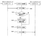
図4は、IPアドレス変換装置4において、インタフェース11(プライベートネットワーク1A又は1B)からインタフェース12(グローバルネットワーク2)へIPパケットが転送されるときのIPアドレス変換動作を示すシーケンス図である。
FIG. 4 is a sequence diagram showing an IP address translation operation when an IP packet is transferred from the interface 11 (private network 1A or 1B) to the interface 12 (global network 2) in the IP
プライベートネットワーク1A又は1BからのIPパケットが、IPアドレス変換装置4に与えられると、IPパケットは、インタフェース11を介して、IPアドレス変換部13に受信される(ステップ1000)。
When an IP packet from the private network 1A or 1B is given to the IP
IPアドレス変換部13では、受信したIPパケットの送信元IPアドレス及び送信元ポート番号が抽出される。そして、IPアドレス変換情報100を参照して、プライベート情報102のIPアドレス111及びポート番号112に、受信パケットの送信元IPアドレス及び送信元ポート番号と一致するものがあるか否かが検索される(ステップ1001)。
The IP
そして、一致するIPアドレス変換情報がない場合、IPフロー識別部14により当該受信パケットのIPフローが識別され、このIPフローのIPフロー識別子に対して、受信パケットから抽出した送信元IPアドレス及び送信元ポート番号を対応付けると共に、IPアドレスプールから取得したグローバル情報103のIPアドレス及びポート番号を対応付けて、当該受信パケットのIPアドレス変換情報をIPアドレス変換情報100に登録する(ステップ1002)。
If there is no matching IP address conversion information, the IP
ここで、IPアドレスプールは、グローバルネットワーク2側で使用するIPアドレスのプールであり、例えばIPアドレスの範囲指定やプリフィックス指定等の方法を用いて情報として与えられているものとする。
Here, the IP address pool is a pool of IP addresses used on the
また、ステップ1001で一致するIPアドレス変換情報がある場合、又はステップ1002でIPアドレス変換情報が登録された場合、IPアドレス変換部13により、IPアドレス変換情報に基づくグローバル情報103のIPアドレス102が受信パケットの送信元IPアドレスに、ポート番号122が送信元ポート番号にそれぞれ設定され、IPアドレスが変換される(ステップ1003)
そして、IPアドレス変換部13により変換されたIPパケットは、インタフェース12を介して、グローバルネットワークに送信される(ステップ1004)。
If there is matching IP address translation information in
Then, the IP packet converted by the IP
次に、IPアドレス変換装置4において、グローバルネットワーク2から入力したIPパケットをプライベートネットワーク1A又は1Bに転送する場合の動作を説明する。
Next, the operation when the IP
図5は、IPアドレス変換装置4において、インタフェース12(グローバルネットワーク2)からインタフェース11(プライベートネットワーク1A又は1B)へIPパケットが転送されるときのIPアドレス変換動作を示すシーケンス図である。
FIG. 5 is a sequence diagram showing an IP address translation operation when an IP packet is transferred from the interface 12 (global network 2) to the interface 11 (private network 1A or 1B) in the IP
まず、グローバルネットワーク2からのIPパケットが、IPアドレス変換装置4に与えられると、IPパケットは、インタフェース12を介して、IPアドレス変換部13に受信される(ステップ1100)。
First, when an IP packet from the
このとき、IPフロー識別部14により当該受信パケットが属するフローが識別される。また、IPアドレス変換部13により、当該受信パケットの宛先IPアドレス及び宛先ポート番号が抽出される。そして、IPアドレス変換部13によりIPアドレス変換情報100が参照され、IPフロー識別部14により識別されたIPフロー識別子が存在し、かつ、プライベート情報102のIPアドレス111及びポート番号112に、受信パケットの送信元IPアドレス及び送信元ポート番号と一致するものがあるか否かが検索される(ステップ1101)。
At this time, the IP
そして、IPアドレス変換情報100に登録がない場合、IPアドレス変換部13により到達不可と判断され、受信したIPパケットは廃棄される(ステップ1102)。
If there is no registration in the IP
このとき、IPアドレス変換装置4の適用箇所により、受信したIPパケットの送信元IPアドレスに対し、ICMP到達不可能パケットを返却するようにしてもよい。
At this time, the ICMP unreachable packet may be returned to the transmission source IP address of the received IP packet depending on the application location of the IP
また、IPアドレス変換情報100に登録がある場合、IPアドレス変換部13により、検索したIPアドレス変換情報に基づくプライベート情報102のIPアドレス111が受信したIPパケットの宛先IPアドレスに、ポート番号112が宛先ポート番号に、それぞれ設定され、IPアドレスが変換される(ステップ1103)。
If the IP
そして、IPアドレス変換部13により変換されたIPパケットは、インタフェース11を介して、プライベートネットワーク1A又は1Bに送信される(ステップ1104)。
Then, the IP packet converted by the IP
(A−3)第1の実施形態の効果
以上のように、第1の実施形態によれば、IPフロー毎にグローバル情報を割り当てることで、プライべ−トネットワークの同一IP端末に終端するIPフローを、グローバルネットワークに対して異なるIP端末に終端するIPフローとして見せることができる。その結果、グローバルネットワークからの攻撃に対するセキュリティ強度を高めることができる。
(A-3) Effect of First Embodiment As described above, according to the first embodiment, IP that terminates at the same IP terminal in a private network by allocating global information for each IP flow. The flow can be shown as an IP flow that terminates on a different IP terminal for the global network. As a result, the security strength against attacks from the global network can be increased.
(B)他の実施形態
(B−1)第1の実施形態において、IPアドレス変換部13は、IPアドレス変換情報100の各IPアドレス変換情報について、定期的にその利用状況を監視し、一定期間使用されない場合は削除するようにしてもよい。また、TCP等のセッション(IPフロー)の切断が検出できるものは、その情報を基に、該当するIPアドレス変換情報100のIPアドレス変換情報を削除してもよい。
(B) Other Embodiments (B-1) In the first embodiment, the IP
(B−2)第1の実施形態の動作の説明では、プライベートネットワークおよびグローバルネットワーク共にIPv4を例としているが、IPv6−IPv6,IPv4−IPv6,IPv6−IPv4、の組み合わせでも適用可能である。特にグローバルネットワークに、IPアドレス空間に制限のないIPv6を用いる組み合わせにおいて大きな効果を発揮する。 (B-2) In the description of the operation of the first embodiment, IPv4 is taken as an example for both the private network and the global network, but a combination of IPv6-IPv6, IPv4-IPv6, IPv6-IPv4 is also applicable. In particular, a great effect is exhibited in a combination using IPv6 that has no restriction on the IP address space in the global network.
(B−3)第1の実施形態において、アプリケーションによっては、複数のIPフローが同一IPアドレスに終端することを前提にして動作するものもあるため、さらにALG(アプリケーションレベルゲートウェイ)を実装し、従来のIPアドレス変換と第1の実施形態のアドレス変換装置4の動作とを使い分けることが望ましい。
(B-3) In the first embodiment, some applications operate on the assumption that a plurality of IP flows terminate at the same IP address. Therefore, an ALG (application level gateway) is further implemented, It is desirable to properly use the conventional IP address translation and the operation of the
1A及び1B…プライベートネットワーク、2…グローバルネットワーク、3A及び3B…IP端末、4A及び4B…IPアドレス変換装置、11…インタフェース(プライベートネットワーク側)、12…インタフェース(グローバルネットワーク側)、13…IPアドレス変換部、14…フロー識別部、100…IPアドレス変換情報。 DESCRIPTION OF SYMBOLS 1A and 1B ... Private network, 2 ... Global network, 3A and 3B ... IP terminal, 4A and 4B ... IP address converter, 11 ... Interface (private network side), 12 ... Interface (global network side), 13 ... IP address Conversion unit, 14... Flow identification unit, 100... IP address conversion information.
Claims (4)
入力パケットのヘッダ情報に基づいてフローを識別するフロー識別手段と、
上記フロー識別手段により識別されたフローに対して、上記グローバルネットワークで用いるグローバルアドレス情報を割り当て、当該フローの終端を示すプライベートアドレス情報を対応付けたアドレス変換情報を作成するアドレス変換情報作成手段と、
入力パケットのアドレス情報が上記アドレス変換情報に登録されている場合に、上記アドレス変換情報を参照して、当該アドレス情報を対応するアドレス情報に変換するアドレス変換手段と
を備えることを特徴とするアドレス変換装置。 In an address translation device that translates address information of packets communicated between a private network and a global network,
Flow identification means for identifying a flow based on header information of an input packet;
Address translation information creating means for assigning global address information used in the global network to the flow identified by the flow identifying means, and creating address translation information in association with private address information indicating the end of the flow;
An address conversion means for referring to the address conversion information and converting the address information into corresponding address information when the address information of the input packet is registered in the address conversion information. Conversion device.
上記アドレス変換手段は、入力パケットの宛先アドレス情報を抽出し、この抽出した宛先アドレス情報が上記アドレス変換情報に登録されていない場合に、当該入力パケットを廃棄するものであることを特徴とする請求項1に記載のアドレス変換装置。 When a packet to be transferred from the global network to the private network is entered,
The address translation unit extracts destination address information of an input packet, and discards the input packet when the extracted destination address information is not registered in the address translation information. Item 2. The address translation device according to Item 1.
フロー識別手段、アドレス変換情報作成手段及びアドレス変換手段を備え、
上記フロー識別手段が、入力パケットのヘッダ情報に基づいてフローを識別するフロー識別工程と、
上記アドレス変換情報作成手段が、上記フロー識別手段により識別されたフローに対して、上記グローバルネットワークで用いるグローバルアドレス情報を割り当て、当該フローの終端を示すプライベートアドレス情報を対応付けたアドレス変換情報を作成するアドレス変換情報作成工程と、
上記アドレス変換手段が、入力パケットのアドレス情報が上記アドレス変換情報に登録されている場合に、上記アドレス変換情報を参照して、当該アドレス情報を対応するアドレス情報に変換するアドレス変換工程と
を有することを特徴とするアドレス変換方法。 In an address conversion method for converting address information of packets communicated between a private network and a global network,
Comprising flow identification means, address translation information creation means and address translation means,
A flow identification step in which the flow identification means identifies a flow based on header information of an input packet;
The address translation information creation means assigns global address information used in the global network to the flow identified by the flow identification means, and creates address translation information in association with private address information indicating the end of the flow Address conversion information creation process to
The address conversion means includes an address conversion step of referring to the address conversion information and converting the address information into corresponding address information when the address information of the input packet is registered in the address conversion information. An address conversion method characterized by the above.
Priority Applications (1)
| Application Number | Priority Date | Filing Date | Title |
|---|---|---|---|
| JP2008037655A JP4835604B2 (en) | 2008-02-19 | 2008-02-19 | Address translation apparatus and method |
Applications Claiming Priority (1)
| Application Number | Priority Date | Filing Date | Title |
|---|---|---|---|
| JP2008037655A JP4835604B2 (en) | 2008-02-19 | 2008-02-19 | Address translation apparatus and method |
Publications (2)
| Publication Number | Publication Date |
|---|---|
| JP2009200607A true JP2009200607A (en) | 2009-09-03 |
| JP4835604B2 JP4835604B2 (en) | 2011-12-14 |
Family
ID=41143680
Family Applications (1)
| Application Number | Title | Priority Date | Filing Date |
|---|---|---|---|
| JP2008037655A Active JP4835604B2 (en) | 2008-02-19 | 2008-02-19 | Address translation apparatus and method |
Country Status (1)
| Country | Link |
|---|---|
| JP (1) | JP4835604B2 (en) |
Cited By (1)
| Publication number | Priority date | Publication date | Assignee | Title |
|---|---|---|---|---|
| JP2014155007A (en) * | 2013-02-07 | 2014-08-25 | Mitsubishi Electric Corp | Smart meter, and smart meter system |
Citations (7)
| Publication number | Priority date | Publication date | Assignee | Title |
|---|---|---|---|---|
| JPH11150566A (en) * | 1997-11-14 | 1999-06-02 | Hitachi Ltd | Internetwork device |
| JP2002261788A (en) * | 2001-02-27 | 2002-09-13 | Mitsubishi Electric Corp | Firewall managing apparatus and method |
| JP2003333065A (en) * | 2002-05-09 | 2003-11-21 | Yamaha Corp | Communication method, communication device, and program |
| JP2005130453A (en) * | 2004-08-03 | 2005-05-19 | Matsushita Electric Ind Co Ltd | Customer premise terminal and communication system |
| JP2006254337A (en) * | 2005-03-14 | 2006-09-21 | Nippon Telegr & Teleph Corp <Ntt> | Network apparatus and traffic count method |
| WO2007062925A1 (en) * | 2005-11-30 | 2007-06-07 | Thomson Licensing | Device and method to detect applications running on a local network for automatically performing the network address translation |
| JP2007208693A (en) * | 2006-02-02 | 2007-08-16 | Toshiba Corp | Communication device, communication system, communication method, and communication program |
-
2008
- 2008-02-19 JP JP2008037655A patent/JP4835604B2/en active Active
Patent Citations (7)
| Publication number | Priority date | Publication date | Assignee | Title |
|---|---|---|---|---|
| JPH11150566A (en) * | 1997-11-14 | 1999-06-02 | Hitachi Ltd | Internetwork device |
| JP2002261788A (en) * | 2001-02-27 | 2002-09-13 | Mitsubishi Electric Corp | Firewall managing apparatus and method |
| JP2003333065A (en) * | 2002-05-09 | 2003-11-21 | Yamaha Corp | Communication method, communication device, and program |
| JP2005130453A (en) * | 2004-08-03 | 2005-05-19 | Matsushita Electric Ind Co Ltd | Customer premise terminal and communication system |
| JP2006254337A (en) * | 2005-03-14 | 2006-09-21 | Nippon Telegr & Teleph Corp <Ntt> | Network apparatus and traffic count method |
| WO2007062925A1 (en) * | 2005-11-30 | 2007-06-07 | Thomson Licensing | Device and method to detect applications running on a local network for automatically performing the network address translation |
| JP2007208693A (en) * | 2006-02-02 | 2007-08-16 | Toshiba Corp | Communication device, communication system, communication method, and communication program |
Cited By (1)
| Publication number | Priority date | Publication date | Assignee | Title |
|---|---|---|---|---|
| JP2014155007A (en) * | 2013-02-07 | 2014-08-25 | Mitsubishi Electric Corp | Smart meter, and smart meter system |
Also Published As
| Publication number | Publication date |
|---|---|
| JP4835604B2 (en) | 2011-12-14 |
Similar Documents
| Publication | Publication Date | Title |
|---|---|---|
| US7639686B2 (en) | Access network clusterhead for providing local mobility management of a roaming IPv4 node | |
| US8184659B2 (en) | Network system for communicating between different IP versions with multiple translators | |
| JP5054114B2 (en) | Method and apparatus for interfacing an IP network | |
| US7443880B2 (en) | Arrangement for reaching IPv4 public network nodes by a node in a IPv4 private network via an IPv6 access network | |
| US20130010614A1 (en) | METHOD AND APPARATUS FOR PROCESSING PACKETS IN IPv6 NETWORK | |
| JP5239618B2 (en) | Address translation apparatus, method and program, and node | |
| JP2004364141A (en) | Ip address conversion device and packet transfer device | |
| JP2011526755A (en) | Method for receiving data packets from IPv4 domain in IPv6 domain, and related devices and access equipment | |
| Babatunde et al. | A comparative review of internet protocol version 4 (ipv4) and internet protocol version 6 (ipv6) | |
| Amoss et al. | Handbook of IPv4 to IPv6 transition: Methodologies for institutional and corporate networks | |
| TWI558149B (en) | Network transmission method and network transmission system for a multi-layer network address translator structure | |
| JP6386166B2 (en) | Translation method and apparatus between IPv4 and IPv6 | |
| Cui et al. | Lightweight 4over6: An extension to the dual-stack lite architecture | |
| JP4572938B2 (en) | Address translation method | |
| JP2009010606A (en) | Tunnel connection system, tunnel control server, tunnel connecting device, and tunnel connection method | |
| JP5333095B2 (en) | Address conversion / protocol conversion system, translator device and translator program | |
| KR20070104348A (en) | Efficient address-space extension to pseudo multi-homed hosts | |
| JP4835604B2 (en) | Address translation apparatus and method | |
| KR20060091555A (en) | Ipv6 internet gateway for inter-working between ipv4 network and ipv6 network and communication method thereof | |
| Cui et al. | State management in IPv4 to IPv6 transition | |
| EP2509284A1 (en) | Method and system for allocating local transport address, media gateway and media gateway controller | |
| Xia et al. | An IPv6 translation scheme for small and medium scale deployment | |
| CN108337331B (en) | Network penetration method, device and system and network connectivity checking method | |
| JP2008079059A (en) | COMMUNICATION EQUIPMENT WHICH PROCESSES MULTIPLE SESSIONS OF IPsec, AND PROCESSING METHOD THEREOF | |
| JP2012209847A (en) | Return communication method in ipv6 nat device |
Legal Events
| Date | Code | Title | Description |
|---|---|---|---|
| A977 | Report on retrieval |
Free format text: JAPANESE INTERMEDIATE CODE: A971007 Effective date: 20100621 |
|
| A131 | Notification of reasons for refusal |
Free format text: JAPANESE INTERMEDIATE CODE: A131 Effective date: 20100706 |
|
| A521 | Written amendment |
Free format text: JAPANESE INTERMEDIATE CODE: A523 Effective date: 20100831 |
|
| A131 | Notification of reasons for refusal |
Free format text: JAPANESE INTERMEDIATE CODE: A131 Effective date: 20101012 |
|
| A521 | Written amendment |
Free format text: JAPANESE INTERMEDIATE CODE: A523 Effective date: 20101203 |
|
| A131 | Notification of reasons for refusal |
Free format text: JAPANESE INTERMEDIATE CODE: A131 Effective date: 20110111 |
|
| A521 | Written amendment |
Free format text: JAPANESE INTERMEDIATE CODE: A523 Effective date: 20110304 |
|
| A02 | Decision of refusal |
Free format text: JAPANESE INTERMEDIATE CODE: A02 Effective date: 20110405 |
|
| A521 | Written amendment |
Free format text: JAPANESE INTERMEDIATE CODE: A523 Effective date: 20110701 |
|
| A911 | Transfer of reconsideration by examiner before appeal (zenchi) |
Free format text: JAPANESE INTERMEDIATE CODE: A911 Effective date: 20110708 |
|
| A131 | Notification of reasons for refusal |
Free format text: JAPANESE INTERMEDIATE CODE: A131 Effective date: 20110809 |
|
| A521 | Written amendment |
Free format text: JAPANESE INTERMEDIATE CODE: A523 Effective date: 20110809 |
|
| TRDD | Decision of grant or rejection written | ||
| A01 | Written decision to grant a patent or to grant a registration (utility model) |
Free format text: JAPANESE INTERMEDIATE CODE: A01 Effective date: 20110830 |
|
| A01 | Written decision to grant a patent or to grant a registration (utility model) |
Free format text: JAPANESE INTERMEDIATE CODE: A01 |
|
| A61 | First payment of annual fees (during grant procedure) |
Free format text: JAPANESE INTERMEDIATE CODE: A61 Effective date: 20110912 |
|
| FPAY | Renewal fee payment (event date is renewal date of database) |
Free format text: PAYMENT UNTIL: 20141007 Year of fee payment: 3 |
|
| R150 | Certificate of patent or registration of utility model |
Ref document number: 4835604 Country of ref document: JP Free format text: JAPANESE INTERMEDIATE CODE: R150 Free format text: JAPANESE INTERMEDIATE CODE: R150 |