JP2009194880A - Communication method, base station equipment using it, terminal apparatus, and communication system - Google Patents
Communication method, base station equipment using it, terminal apparatus, and communication system Download PDFInfo
- Publication number
- JP2009194880A JP2009194880A JP2008036711A JP2008036711A JP2009194880A JP 2009194880 A JP2009194880 A JP 2009194880A JP 2008036711 A JP2008036711 A JP 2008036711A JP 2008036711 A JP2008036711 A JP 2008036711A JP 2009194880 A JP2009194880 A JP 2009194880A
- Authority
- JP
- Japan
- Prior art keywords
- wireless device
- communication
- unit
- period
- base station
- Prior art date
- Legal status (The legal status is an assumption and is not a legal conclusion. Google has not performed a legal analysis and makes no representation as to the accuracy of the status listed.)
- Pending
Links
Images


Classifications
-
- H—ELECTRICITY
- H04—ELECTRIC COMMUNICATION TECHNIQUE
- H04W—WIRELESS COMMUNICATION NETWORKS
- H04W88/00—Devices specially adapted for wireless communication networks, e.g. terminals, base stations or access point devices
- H04W88/08—Access point devices
- H04W88/10—Access point devices adapted for operation in multiple networks, e.g. multi-mode access points
-
- H—ELECTRICITY
- H04—ELECTRIC COMMUNICATION TECHNIQUE
- H04W—WIRELESS COMMUNICATION NETWORKS
- H04W84/00—Network topologies
- H04W84/18—Self-organising networks, e.g. ad-hoc networks or sensor networks
-
- H—ELECTRICITY
- H04—ELECTRIC COMMUNICATION TECHNIQUE
- H04W—WIRELESS COMMUNICATION NETWORKS
- H04W88/00—Devices specially adapted for wireless communication networks, e.g. terminals, base stations or access point devices
- H04W88/02—Terminal devices
- H04W88/06—Terminal devices adapted for operation in multiple networks or having at least two operational modes, e.g. multi-mode terminals
-
- H—ELECTRICITY
- H04—ELECTRIC COMMUNICATION TECHNIQUE
- H04W—WIRELESS COMMUNICATION NETWORKS
- H04W92/00—Interfaces specially adapted for wireless communication networks
- H04W92/16—Interfaces between hierarchically similar devices
- H04W92/18—Interfaces between hierarchically similar devices between terminal devices
Abstract
Description
本発明は、通信技術に関し、特に基地局装置と端末装置との間において信号を通信するとともに、複数の端末装置間において信号を通信する通信方法およびそれを利用した基地局装置、端末装置、通信システムに関する。 The present invention relates to a communication technique, and more particularly to a communication method for communicating a signal between a base station apparatus and a terminal apparatus and communicating a signal between a plurality of terminal apparatuses, and a base station apparatus, a terminal apparatus, and a communication using the communication method About the system.
IEEE802.11等の規格に準拠した無線LAN(Local Area Network)システムのネットワーク構成には、主に、インフラストラクチャー・モードとアドホック・モードの2種類がある。インフラストラクチャー・モードとは、基地局装置と端末装置とが接続され、端末装置が基地局装置を介して通信する形態である。一方、アドホック・モードとは、基地局装置を必要とせず、端末装置同士が直接通信する形態である(例えば、非特許文献1参照)。
一般的に、インフラストラクチャー・モードとアドホック・モードとの切替は、ユーザによって手動的になされる。つまり、ユーザは、通信を実行する前に、端末装置に対して、インフラストラクチャー・モードあるいはアドホック・モードを設定する。そのため、端末装置は、インフラストラクチャー・モードとアドホック・モードとを並行的に実行できない。しかしながら、インフラストラクチャー・モードとアドホック・モードとを並行的に実行したいという状況が存在する。例えば、ここでは、基地局装置が道路に設置され、端末装置が車両に設置されている状況を想定する。なお、車両には、車載用撮像装置も備えられている。車両の走行中、端末装置は、インフラストラクチャー・モードにて、基地局装置を介してネットワークに接続する。また、車両が停止したときに、端末装置は、アドホック・モードにて、撮像した画像を他の端末装置へ送信する。このような状況においては、インフラストラクチャー・モードとアドホック・モードとが自動的に切りかえられる方が望ましい。 Generally, switching between the infrastructure mode and the ad hoc mode is manually performed by the user. That is, the user sets the infrastructure mode or the ad hoc mode for the terminal device before executing communication. Therefore, the terminal device cannot execute the infrastructure mode and the ad hoc mode in parallel. However, there is a situation where it is desired to execute the infrastructure mode and the ad hoc mode in parallel. For example, here, it is assumed that the base station device is installed on a road and the terminal device is installed on a vehicle. The vehicle is also provided with an in-vehicle imaging device. While the vehicle is traveling, the terminal device is connected to the network via the base station device in the infrastructure mode. When the vehicle stops, the terminal device transmits the captured image to another terminal device in the ad hoc mode. In such a situation, it is desirable to automatically switch between the infrastructure mode and the ad hoc mode.
本発明はこうした状況に鑑みてなされたものであり、その目的は、インフラストラクチャー・モードとアドホック・モードとを自動的に切りかえる通信技術を提供することにある。 The present invention has been made in view of such circumstances, and an object of the present invention is to provide a communication technique for automatically switching between an infrastructure mode and an ad hoc mode.
上記課題を解決するために、本発明のある態様の無線装置は、少なくとも第1の無線装置および第2の無線装置と通信する無線装置であって、本無線装置とは異なった種類の第1の無線装置および第2の無線装置との通信を実行する通信部と、通信部における通信を制御する制御部とを備える。制御部は、所定の期間にわたって、第1の無線装置と第2の無線装置との間の直接の通信を許可するとともに、通信部を介して、許可した直接の通信の実行を第1の無線装置および第2の無線装置へ指示する。 In order to solve the above-described problem, a wireless device according to an aspect of the present invention is a wireless device that communicates with at least the first wireless device and the second wireless device, and is a first type different from the wireless device. A communication unit that performs communication with the wireless device and the second wireless device, and a control unit that controls communication in the communication unit. The control unit permits direct communication between the first wireless device and the second wireless device over a predetermined period, and performs the permitted direct communication via the communication unit via the first wireless device. Instruct the device and the second wireless device.
本発明の別の態様もまた、無線装置である。この装置は、少なくとも第1の無線装置および第2の無線装置と通信する無線装置であって、本無線装置とは異なった種類の第1の無線装置との通信を実行する通信部と、通信部における通信を制御する制御部と、制御部は、通信部を介して第1の無線装置から、所定の期間にわたって、第1の無線装置に接続された第2の無線装置であって、かつ本無線装置と同一の種類の第2の無線装置との直接の通信を実行する旨の指示を受けつける受付部と、受付部において指示を受けつけた場合に、指示された期間にわたって、通信部の通信対象を第1の無線装置から第2の無線装置へ切りかえる切替部とを備える。 Another aspect of the present invention is also a wireless device. This device is a wireless device that communicates with at least a first wireless device and a second wireless device, and a communication unit that performs communication with a first wireless device of a type different from the wireless device, and a communication A control unit that controls communication in the unit, and the control unit is a second wireless device connected to the first wireless device over a predetermined period from the first wireless device via the communication unit, and A reception unit that receives an instruction to execute direct communication with a second wireless device of the same type as the wireless device, and communication of the communication unit over the specified period when the reception unit receives the instruction. A switching unit that switches the target from the first wireless device to the second wireless device.
本発明のさらに別の態様は、通信システムである。この通信システムは、第1種の無線装置と、第1種の無線装置との通信を実行する複数の第2種の無線装置とを備える。第1種の無線装置は、所定の期間にわたって、複数の第2種の無線装置のうちのふたつに対する直接の通信を許可するとともに、許可した直接の通信の実行を少なくともふたつの第2種の無線装置へ指示し、複数の第2種の無線装置のうちのふたつは、指示された期間にわたって、第2種の無線装置間での直接の通信を実行する。 Yet another embodiment of the present invention is a communication system. The communication system includes a first type of wireless device and a plurality of second type of wireless devices that perform communication with the first type of wireless device. The first type of wireless device permits direct communication to two of the plurality of second type of wireless devices over a predetermined period of time, and at least two second type of wireless devices execute the permitted direct communication. Instructing the device, two of the plurality of second-type wireless devices perform direct communication between the second-type wireless devices over the designated period.
本発明のさらに別の態様は、通信方法である。この方法は、少なくとも第1の無線装置および第2の無線装置と通信する無線装置において、本無線装置とは異なった種類の第1の無線装置および第2の無線装置との通信を実行するステップと、所定の期間にわたって、第1の無線装置と第2の無線装置との間の直接の通信を許可するステップと、許可した直接の通信の実行を第1の無線装置および第2の無線装置へ指示するステップと、を備える。 Yet another embodiment of the present invention is a communication method. In this method, at least a wireless device communicating with a first wireless device and a second wireless device performs communication with a first wireless device and a second wireless device of a different type from the wireless device. And permitting direct communication between the first radio apparatus and the second radio apparatus over a predetermined period, and executing the permitted direct communication in the first radio apparatus and the second radio apparatus. And instructing to.
本発明のさらに別の態様もまた、通信方法である。この方法は、少なくとも第1の無線装置および第2の無線装置と通信する無線装置において、本無線装置とは異なった種類の第1の無線装置との通信を実行するステップと、第1の無線装置から、所定の期間にわたって、第1の無線装置に接続された第2の無線装置であって、かつ本無線装置と同一の種類の第2の無線装置との直接の通信を実行する旨の指示を受けつけるステップと、指示を受けつけた場合に、指示された期間にわたって、通信対象を第1の無線装置から第2の無線装置へ切りかえるステップと、を備える。 Yet another embodiment of the present invention is also a communication method. In this method, at least a wireless device communicating with a first wireless device and a second wireless device performs communication with a first wireless device of a type different from the wireless device, and a first wireless device A direct communication from a device to a second wireless device connected to the first wireless device over a predetermined period and of the same type as the second wireless device. A step of receiving an instruction, and a step of switching the communication target from the first wireless device to the second wireless device over the specified period when the instruction is received.
なお、以上の構成要素の任意の組合せ、本発明の表現を方法、装置、システム、記録媒体、コンピュータプログラムなどの間で変換したものもまた、本発明の態様として有効である。 It should be noted that any combination of the above-described constituent elements and a conversion of the expression of the present invention between a method, an apparatus, a system, a recording medium, a computer program, etc. are also effective as an aspect of the present invention.
インフラストラクチャー・モードとアドホック・モードとを自動的に切りかえることができる。 It is possible to automatically switch between the infrastructure mode and the ad hoc mode.
本発明を具体的に説明する前に、概要を述べる。本発明の実施例は、無線LANシステムのごとく、基地局装置と端末装置によって構成される通信システムに関する。また、通信システムでは、インフラストラクチャー・モードとアドホック・モードとが規定されている。このような状況下において、インフラストラクチャー・モードとアドホック・モードとを自動的に切りかえるために、本実施例に係る通信システムは、次の処理を実行する。通常、端末装置は、インフラストラクチャー・モードに設定されており、基地局装置との通信を実行する。 Before describing the present invention in detail, an outline will be described. An embodiment of the present invention relates to a communication system including a base station device and a terminal device, as in a wireless LAN system. In the communication system, an infrastructure mode and an ad hoc mode are defined. Under such circumstances, in order to automatically switch between the infrastructure mode and the ad hoc mode, the communication system according to the present embodiment executes the following processing. Normally, the terminal device is set to the infrastructure mode and executes communication with the base station device.
端末装置がアドホック・モードへの変更を希望する場合、端末装置は、アドホック・モードへの変更の要求とその際の送信先とを基地局装置へ通知する。基地局装置は、通知を受けつけると、所定の期間にわたって、当該端末装置と送信先となる端末装置とに対してアドホック・モードへの変更を許可し、少なくともふたつの端末装置へ許可の内容を通知する。ふたつの端末装置は、許可された期間にわたって、アドホック・モードによる通信を実行する。なお、その期間においても、他の端末装置は、インフラストラクチャー・モードに設定されており、基地局装置との通信を実行する。このように、アドホック・モードを許可している端末装置および期間を基地局装置が管理することによって、インフラストラクチャー・モードとアドホック・モードとの自動的な切替が実現される。 When the terminal device desires to change to the ad hoc mode, the terminal device notifies the base station device of the request for changing to the ad hoc mode and the transmission destination at that time. Upon receiving the notification, the base station device permits the terminal device and the destination terminal device to change to the ad hoc mode over a predetermined period, and notifies the content of the permission to at least two terminal devices. To do. The two terminal devices perform communication in the ad hoc mode over a permitted period. Also during that period, the other terminal devices are set to the infrastructure mode and execute communication with the base station device. As described above, the base station device manages the terminal device and the period in which the ad hoc mode is permitted, thereby realizing automatic switching between the infrastructure mode and the ad hoc mode.
図1は、本発明の実施例に係る通信システム100の構成を示す。通信システム100は、端末装置10と総称される第1端末装置10a、第2端末装置10b、第3端末装置10c、基地局装置12、ネットワーク18を含む。また、第1端末装置10aは、第1端末用アンテナ14aを含み、第2端末装置10bは、第2端末用アンテナ14bを含み、第3端末装置10cは、第3端末用アンテナ14cを含み、基地局装置12は、基地局用アンテナ16を含む。また、第1端末用アンテナ14a、第2端末用アンテナ14b、第3端末用アンテナ14cは、端末用アンテナ14と総称される。
FIG. 1 shows a configuration of a
基地局装置12は、一端において、基地局用アンテナ16によって無線ネットワークを形成し、他端においてネットワーク18に接続する。端末装置10がインフラストラクチャー・モードである場合に、基地局装置12は、端末装置10と通信することによって、端末装置10とネットワーク18との間、また、端末装置10と他の端末装置10との間でデータを中継する。一方、端末装置10がアドホック・モードである場合、基地局装置12は、端末装置10間の通信に関与しない。しかしながら、基地局装置12は、所定の期間にわたって、複数の端末装置10のうちのふたつに対する直接の通信、つまりアドホック・モードによる通信を許可する。また、基地局装置12は、許可したアドホック・モードによる通信の実行を少なくともふたつの端末装置10へ指示する。
The
つまり、基地局装置12は、アドホック・モードによる通信には関与しないが、アドホック・モードによる通信の期間をスケジューリングする。基地局装置12によるスケジューリング処理の詳細は、後述する。また、端末装置10は、ふたつの端末装置10がアドホック・モードによる通信を実行している間、他の端末装置10とのインフラストラクチャー・モードによる通信を実行してもよい。なお、通信システム100は、例えばIEEE802.11等の規格に準拠した無線LANシステムを応用した形態に相当する。そのため、インフラストラクチャー・モードによる通信、およびアドホック・モードによる通信には、公知の技術が使用されればよいので、ここでは説明を省略する。
That is, the
端末装置10は、基地局装置12のサービスエリア内に進入して、基地局装置12からのビーコンを受信することによって、基地局装置12との接続を確立する。前述のごとく、端末装置10の通信には、インフラストラクチャー・モードとアドホック・モードとが規定されており、インフラストラクチャー・モードの場合、端末装置10は、基地局装置12との通信を実行する。一方、端末装置10は、基地局装置12からのビーコンにて、アドホック・モードの通信期間(以下、「アドホック期間」という)が指示されている場合、当該アドホック期間にわたって、アドホック・モードによる通信を実行する。端末装置10におけるインフラストラクチャー・モードとアドホック・モードとの切替の説明は、後述する。なお、ここでは、アドホック期間に対応して、インフラストラクチャー・モードの通信期間を「インフラストラクチャー期間」という。
The
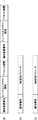
図2(a)−(c)は、通信システム100におけるパケットフォーマットを示す。図2(a)は、基地局装置12から報知されるビーコンの一部に含まれる情報のフォーマットを示す。図示のごとく、「端末装置番号」、「インフラストラクチャー期間」、「アドホック期間」がひとつの組合せとして、当該組合せが複数含まれている。端末装置番号には、図1に示された各端末装置10を特定するための情報が含まれる。また、インフラストラクチャー期間およびアドホック期間は、当該端末装置10に対する値が含まれる。ここで、通信システム100では、時刻の情報が共有されており、インフラストラクチャー期間およびアドホック期間は、当該時刻によって示されている。例えば、インフラストラクチャー期間には、インフラストラクチャー期間の開始時刻と終了時刻が含まれる。アドホック期間も、同様である。なお、端末装置番号が示されていない端末装置10には、暗示的にインフラストラクチャー・モードでの動作が指示されているものとする。
2A to 2C show packet formats in the
図2(b)は、端末装置10から基地局装置12へ送信される要求信号のフォーマットを示す。通信システム100において、基地局装置12がビーコンを送信した後の所定の期間が、「アドミッション期間」として規定されている。端末装置10は、アドミッション期間において要求信号を送信する。要求信号の一例は、通信システム100への参加要求であり、これは基地局装置12への接続要求ともいえる。その際、「信号種別」には、参加要求として予め定められた値が入力されている。また、QoS要求パラメータには、QoSクラス、遅延・スループット等の要求値が含まれる。これは、公知の技術でよいので、ここでは、説明を省略する。また、アドホック・モードによる通信を要求する場合、通信対象となる端末装置10を特定するための端末装置番号とデータ量とが含まれる。また、要求信号が変更要求である場合、「信号種別」には、変更要求として予め定められた値が入力されている。変更要求とは、端末装置10が既に送信したQoS要求パラメータの内容を変更する場合に使用される信号である。
FIG. 2B shows a format of a request signal transmitted from the
図2(c)は、基地局装置12から端末装置10へ送信される応答信号のフォーマットを示す。基地局装置12は、アドミッション期間において要求信号を受信した場合、当該要求信号に対する応答信号を端末装置10へ送信する。要求信号が参加要求である場合、応答信号として参加応答が送信され、要求信号が変更要求である場合、応答信号として変更応答が送信される。その際、信号種別には、参加応答あるいは変更信号として予め定められた値が入力されている。また、QoS応答パラメータには、QoS要求パラメータに対応した値が含まれている。
FIG. 2C shows a format of a response signal transmitted from the
図3は、通信システム100における通信手順の概要を示す。図1に対応するように、基地局装置12、第1端末装置10a、第2端末装置10b、第3端末装置10cが示されている。ここで、図3における「B」はビーコンを示し、「Q」は要求信号を示し、「S」は応答信号を示す。また、「D」はデータ信号を示し、「A」はAck信号を示す。さらに、「A期間」はアドホック期間を示し、「I期間」はインフラストラクチャー期間を示す。なお、初期の状態において、第1端末装置10aから第3端末装置10cは、基地局装置12に接続されていないものとする。また、基地局装置12から端末装置10への方向が下り回線に相当し、端末装置10から基地局装置12への方向が上り回線に相当する。
FIG. 3 shows an outline of a communication procedure in the
基地局装置12は、定期的にビーコンを報知する。また、基地局装置12がビーコンを送信してからの所定の期間がアドミッション期間として規定されている。アドミッション期間とは、端末装置10が基地局装置12に対して接続を要求するために規定された期間である。この期間の間に、基地局装置12との接続を確立していない端末装置10は、基地局装置12からのビーコンを受信することによって、基地局装置12の存在を認識する。また、端末装置10は、基地局装置12へ参加要求を送信する。参加要求は、図2(b)に示された要求信号のフォーマットを有する。ここでは、第1端末装置10aが基地局装置12へ要求信号を送信し、基地局装置12は、第1端末装置10aへ参加応答を応答信号にて送信する。また、第2端末装置10b、第3端末装置10cも同様の動作を実行する。その結果、第1端末装置10aから第3端末装置10cは、基地局装置12に接続される。
The
図示しないアドミッション期間において、少なくとも第1端末装置10aおよび第2端末装置10bは、変更要求を基地局装置12へ送信する。ここで、第1端末装置10aからの変更要求には、第2端末装置10bおよび第3端末装置10cとのアドホック・モードによる通信の要求が含まれており、第2端末装置10bからの変更要求には、第3端末装置10cとのアドホック・モードによる通信の要求が含まれている。基地局装置12は、これらの要求をもとにスケジューリングを行い、図中のふたつ目のビーコンの中にスケジューリング結果を図2(a)のように含めて、ビーコンを報知する。つまり、基地局装置12は、各端末装置10に対してI期間およびA期間を指示する。第1端末装置10aから第3端末装置10cのそれぞれは、ビーコンを受信し、アドミッション期間において、次の要求信号を送信するとともに次の応答信号を受信する。
In an admission period (not shown), at least the first
アドミッション期間終了後、第1端末装置10aは、基地局装置12からの指示にしたがって、A期間の後にI期間になる。I期間において、第1端末装置10aは、基地局装置12からのデータ信号を受信し、それに対応したAck信号を基地局装置12へ送信する。また、I期間に続いてA期間に変更され、第1端末装置10aは、送信対象となる第2端末装置10bがA期間であることを確認した後に、第2端末装置10bへデータ信号を送信する。第2端末装置10bは、アドホック期間において第1端末装置10aからのデータ信号を受信すると、それに対応したAck信号を第1端末装置10aへ送信する。また、第2端末装置10bは、アドホック期間が継続するので、送信対象となる第3端末装置10cがA期間であることを確認した後に、第3端末装置10cへデータ信号を送信する。第3端末装置10cは、アドホック期間において第2端末装置10bからのデータ信号を受信すると、それに対応したAck信号を第2端末装置10bへ送信する。
After the end of the admission period, the first
第2端末装置10bは、A期間からI期間へ変更され、I期間において、基地局装置12からのデータ信号を受信し、それに対応したAck信号を基地局装置12へ送信する。また、第3端末装置10cも、A期間からI期間へ変更され、I期間において、基地局装置12へデータ信号を送信し、それに対応したAck信号を基地局装置12から受信する。さらに、第3端末装置10cは、I期間からA期間へ変更される。また、そのタイミングにおいて、第1端末装置10aもA期間に設定されている。第1端末装置10aは、送信対象となる第3端末装置10cがA期間であることを確認した後に、第3端末装置10cへデータ信号を送信する。第3端末装置10cは、アドホック期間において第1端末装置10aからのデータ信号を受信すると、それに対応したAck信号を第1端末装置10aへ送信する。第3端末装置10cは、A期間からI期間へ変更され、I期間において、基地局装置12へデータ信号を送信し、それに対応したAck信号を基地局装置12から受信する。その後、基地局装置12は、ビーコンを報知する。
The second
図4は、端末装置10の構成を示す。端末装置10は、端末用アンテナ14、パケット通信部20、信号処理部22、制御部24を含む。また、パケット通信部20は、パケット受信部28、パケット送信部30を含み、信号処理部22は、パケット処理部32、パケット生成部34を含み、制御部24は、検出部36、要求部38、受付部40、切替部42を含む。
FIG. 4 shows the configuration of the
パケット受信部28は、端末用アンテナ14において受信したパケット信号に対して、復調処理等を実行する。端末用アンテナ14において受信したパケット信号は、無線周波数領域の信号であるので、パケット受信部28は、パケット信号に対して、無線周波数領域からベースバンド領域への周波数変換を実行した後、復調処理、復号処理を実行し、物理レイヤよりも上位のレイヤにおいて規定されたパケット信号をパケット処理部32に出力する。パケット処理部32は、パケット受信部28からパケット信号を受けつけ、受けつけたパケット信号に含まれたパケット信号にしたがって、接続処理等の上位レイヤでの処理を実行する。上位レイヤとは、物理レイヤよりも上位に規定されるレイヤに相当する。パケット処理部32は、処理結果を制御部24に出力する。ここで、上位レイヤの処理として公知の技術が使用されればよいので、説明を省略する。
The
パケット生成部34は、制御部24からの情報を受けつけ、情報をもとにパケット信号を生成する。パケット生成部34において生成されるパケット信号は、パケット処理部32に入力されるパケット信号と同様に、物理レイヤよりも上位のレイヤにおいて規定されたパケット信号に相当する。パケット生成部34は、生成したパケット信号をパケット送信部30に出力する。パケット送信部30は、パケット生成部34からのパケット信号に対して、符号化処理、変調処理を実行する。また、パケット送信部30は、変調したパケット信号に対して、ベースバンド領域から無線周波数領域への周波数変換を実行した後、周波数変換したパケット信号を端末用アンテナ14から送信する。パケット受信部28とパケット送信部30での処理が無線通信処理に相当する。
The
制御部24は、端末装置10における通信動作を制御する。ここでは、図示しない基地局装置12との接続処理、アドホック・モードによる通信の要求処理、インフラストラクチャー・モードとアドホック・モードとの切替による通信処理の順に説明する。まずは、基地局装置12との接続処理を説明する。制御部24は、パケット受信部28、パケット処理部32を介して、図示しない基地局装置12からのビーコンを受けつけることによって、基地局装置12の存在を認識する。また、制御部24は、パケット生成部34に対して、当該基地局装置12への参加要求の生成を指示する。制御部24は、パケット生成部34、パケット送信部30に対して、参加要求を基地局装置12へ送信させる。その後、制御部24は、パケット受信部28、パケット処理部32を介して、基地局装置12からの参加応答を受けつけることによって、基地局装置12との接続を確立する。その結果、端末装置10と基地局装置12との通信が可能になる。
The
次には、アドホック・モードによる通信の要求処理を説明する。検出部36は、端末装置10において実行されているアプリケーションにおいて発生したデータの宛先を確認する。その結果、検出部36は、基地局装置12に接続された他の端末装置10宛のデータの存在を検出する。検出部36は、データの存在を検出した場合、その旨を要求部38へ通知する。また、その際、検出部36は、データの宛先となる他の端末装置10の情報も通知する。要求部38は、検出部36から、データの存在を検出した旨の通知と当該データの宛先となる他の端末装置10の通知とを受けつける。要求部38は、パケット生成部34に対して、要求信号の生成を指示する。当該要求信号は、参加要求または変更要求である。また、要求部38は、当該要求信号に、他の端末装置10に対するアドホック・モードによる通信の要求、および宛先となる他の端末装置10の情報を含めさせる。パケット生成部34、パケット送信部30は、前述のアドミッション期間において、要求信号を基地局装置12へ送信する。
Next, communication request processing in the ad hoc mode will be described. The
さらには、インフラストラクチャー・モードとアドホック・モードとの切替による通信処理を説明する。受付部40は、パケット受信部28、パケット処理部32を介して、基地局装置12からのビーコンを受けつける。受付部40は、ビーコンの中から、スケジューリングに関する部分、つまり図2(a)に示された部分を抽出する。特に、受付部40は、自らに対するスケジューリングに関する部分を抽出する。その結果、受付部40は、基地局装置12から、アドホック期間にわたって、当該基地局装置12に接続された他の端末装置10とのアドホック・モードによる通信を実行する旨の指示を受けつける。また、受付部40は、インフラストラクチャー期間にわたって、基地局装置12とのインフラストラクチャー・モードによる通信を実行する旨の指示を受けつける。受付部40は、インフラストラクチャー期間およびアドホック期間を切替部42に通知する。
Furthermore, communication processing by switching between the infrastructure mode and the ad hoc mode will be described. The accepting
切替部42は、受付部40からの通知をもとに、インフラストラクチャー期間にわたって、インフラストラクチャー・モードによる通信を実現させる。つまり、通信対象を基地局装置12に設定する。また、切替部42は、アドホック期間にわたって、アドホック・モードによる通信を実現させる。例えば、インフラストラクチャー期間からアドホック期間へ切りかわる場合、切替部42は、通信部の通信対象を基地局装置12から他の端末装置10へ切りかえる。なお、インフラストラクチャー・モードによる通信およびアドホック・モードによる通信には、公知の技術が使用されればよいので、ここでは、説明を省略する。また、アドホック期間において、他の端末装置10へデータを送信する際、制御部24は、スケジューリングに関する部分を参照しながら、当該他の端末装置10もアドホック期間であるかを確認する。アドホック期間であれば、制御部24は、データを送信する。一方、制御部24は、パケット通信部20、信号処理部22に対して、他のふたつの端末装置10がアドホック期間であっても、インフラストラクチャー・モードによる通信を実行させてもよい。
Based on the notification from the receiving
この構成は、ハードウエア的には、任意のコンピュータのCPU、メモリ、その他のLSIで実現でき、ソフトウエア的にはメモリにロードされた通信機能のあるプログラムなどによって実現されるが、ここではそれらの連携によって実現される機能ブロックを描いている。したがって、これらの機能ブロックがハードウエアのみ、ソフトウエアのみ、またはそれらの組合せによっていろいろな形で実現できることは、当業者には理解されるところである。 This configuration can be realized in terms of hardware by a CPU, memory, or other LSI of any computer, and in terms of software, it is realized by a program having a communication function loaded in the memory. Describes functional blocks realized by collaboration. Accordingly, those skilled in the art will understand that these functional blocks can be realized in various forms by hardware only, software only, or a combination thereof.
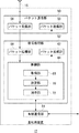
図5は、基地局装置12の構成を示す。基地局装置12は、基地局用アンテナ16、パケット通信部50、信号処理部52、有線通信部54を含む。また、パケット通信部50は、パケット受信部56、パケット送信部58を含み、信号処理部52は、パケット処理部60、パケット生成部62、制御部64を含む。さらに、制御部64は、取得部68、決定部70、指示部72を含む。
FIG. 5 shows the configuration of the
パケット受信部56は、前述のパケット受信部28と同様の処理を実行し、パケット送信部58は、前述のパケット送信部30と同様の処理を実行する。なお、パケット送信部58は、定期的にビーコン信号を送信する。ビーコン信号には、図2(a)に示した情報が含まれている。
The
パケット処理部60は、パケット受信部56からパケット信号を受けつけ、受けつけたパケット信号に含まれたパケット信号にしたがって、接続処理等の上位レイヤでの処理を実行する。前述のごとく、上位レイヤとは、物理レイヤよりも上位に規定されるレイヤに相当する。パケット処理部60は、処理結果を制御部64に出力する。制御部64は、基地局装置12全体の動作、端末装置10に対する接続処理等を制御する。制御部64の詳細は、後述する。
The
パケット生成部62は、制御部64からの指示に応じて、パケット信号を生成する。なお、パケット生成部62において生成されるパケット信号は、パケット処理部60に入力されるパケット信号に対応して、物理レイヤよりも上位のレイヤにおいて規定されたパケット信号に相当する。パケット生成部62は、生成したパケット信号をパケット送信部58に出力する。
The
有線通信部54は、図1のネットワーク18に接続され、ネットワーク18を使用した有線通信を実行する。つまり、有線通信部54は、パケット通信部50、信号処理部52によって受信した図示しない端末装置10からのデータをネットワーク18へ出力する。また、有線通信部54は、ネットワーク18から入力したデータを信号処理部52へ出力する。なお、有線通信部54に対する制御は、制御部64によってなされる。
The
ここで、制御部64の処理を具体的に説明する。前述のごとく、制御部64は、パケット生成部62に定期的にビーコンを生成させ、パケット送信部58にビーコンを送信させる。また、制御部64は、ビーコン送信後の所定の期間をアドミッション期間として規定する。アドミッション期間において、制御部64は、パケット受信部56、パケット処理部60を介して、図示しない端末装置10からの要求信号を受けつける。要求信号が参加要求の場合、接続を許可するのであれば、制御部64は、パケット生成部62、パケット送信部58を介して、参加応答としての応答信号を端末装置10へ送信する。なお、端末装置10に対する接続処理には公知の技術が使用されればよいので、ここでは説明を省略する。また、要求信号が変更要求の場合、制御部64は、パケット生成部62、パケット送信部58を介して、変更応答としての応答信号を端末装置10へ送信する。
Here, the process of the
取得部68は、受けつけた要求信号から、アドホック・モードによる通信の要求と、通信対象となる端末装置10の情報を抽出する。ここでは、アドホック・モードによる通信の要求元の端末装置10を「送信元」といい、通信対象となる端末装置10を「送信先」という。取得部68は、抽出した情報を決定部70へ出力する。
The
決定部70は、取得部68からの情報をもとに、各端末装置10に対するインフラストラクチャー期間およびアドホック期間を決定する。例えば、決定部70は、送信元のアドホック期間と、送信先のアドホック期間とが重複するように、アドホック期間を決定する。また、決定部70は、残りの期間に、インフラストラクチャー期間とアドホック期間とを割り当てる。なお、所定の端末装置10に対してアドホック期間だけを割り当ててもよいし、インフラストラクチャー期間だけを割り当ててもよい。このような処理によって、決定部70は、インフラストラクチャー・モードによる通信を中心としながらも、アドホック期間にわたって、複数の端末装置10のうちのふたつに対するアドホック・モードによる通信を許可する。ここで、決定部70は、各端末装置10に対するインフラストラクチャー期間およびアドホック期間を決定するだけであり、インフラストラクチャー期間およびアドホック期間における通信の制御を実行しない。
The
指示部72は、決定部70におけるスケジューリング結果をもとに、制御部64を介して、パケット生成部62にビーコンを生成させる。ビーコンは、図2(a)に示したフォーマットを有する。つまり、指示部72は、許可したアドホック・モードによる通信の実行を少なくとも送信元と送信先へ指示する。なお、前述のごとく、インフラストラクチャー・モードによる通信およびアドホック・モードによる通信には、公知の技術が使用されればよいので、ここでは、説明を省略する。
The
ここで、送信元と送信先のひとつの組合せが、送信先と送信元の別の組合せになることがある。つまり、ふたつの端末装置10が互いに宛先となっている場合である。例えば、第1端末装置10aからの要求において送信先として第2端末装置10bが指定されるとともに、第2端末装置10bからの要求において送信先として第1端末装置10aが指定される場合である。そのような場合、取得部68は、複数の端末装置10のうちの少なくともふたつから、アドホック・モードによる通信の許可に対する要求信号を受けつける。決定部70は、当該ふたつの端末装置10に対してアドホック・モードによる通信を許可するとともに、各端末装置10に許可するアドホック期間の少なくとも一部を重複させる。なお、制御部64は、パケット通信部50、信号処理部52に対して、ふたつの端末装置10がアドホック期間であっても、当該ふたつの端末装置10以外の端末装置10とのインフラストラクチャー・モードによる通信を実行させる。
Here, one combination of the transmission source and the transmission destination may be another combination of the transmission destination and the transmission source. In other words, this is a case where the two
以上の構成による通信システム100の動作を説明する。図6は、端末装置10における要求信号の送信手順を示すフローチャートである。検出部36は、送信すべきデータの発生を検出する(S10)。当該データが他の端末装置10宛のデータであれば(S12のY)、要求部38は、パケット生成部34に対して、要求信号に対して宛先の情報を含めるように指示する(S14)。また、パケット生成部34、パケット送信部30は、アドミッション期間において要求信号を送信する(S16)。一方、当該データが他の端末装置10宛のデータでなければ(S12のN)、処理は終了される。
The operation of the
図7は、端末装置10における通信手順を示すフローチャートである。受付部40は、ビーコンを受信する(S30)。切替部42は、A期間およびI期間を特定する(S32)。I期間であれば(S34のY)、切替部42は、パケット通信部20、信号処理部22をインフラストラクチャー・モードに設定する(S36)。一方、I期間でなければ(S34のN)、切替部42は、パケット通信部20、信号処理部22をアドホック・モードに設定する(S38)。パケット通信部20、信号処理部22は、通信を実行する(S40)。通信期間が終了しなければ(S42のN)、ステップ34に戻る。通信期間が終了すれば(S42のY)、処理は終了される。
FIG. 7 is a flowchart showing a communication procedure in the
図8は、基地局装置12における通信手順を示すフローチャートである。取得部68は、アドミッション期間において、パケット通信部50、信号処理部52を介して、要求信号を受信する(S60)。また、取得部68は、応答信号を送信する(S62)。決定部70は、スケジューリングを実行する(S64)。指示部72は、パケット生成部62、パケット送信部58に対して、スケジューリング結果が含まれたビーコンの送信を指示する(S66)。パケット通信部50、信号処理部52は、インフラストラクチャー・モードの端末装置10と通信する(S68)。
FIG. 8 is a flowchart showing a communication procedure in the
図9は、基地局装置12におけるスケジューリング手順を示すフローチャートである。これは、決定部70での処理に相当する。アドホック・モードを要求している端末装置10があれば(S80のY)、決定部70は、送信元と送信先に共通のA期間を設定する(S82)。送信元と送信先が互いに逆になっている組合せがあれば(S84のY)、決定部70は、それらのA期間を連続させる(S86)。一方、送信元と送信先が互いに逆になっている組合せがなければ(S84のN)、ステップ86はスキップされる。また、アドホック・モードを要求している端末装置10がなければ(S80のN)、ステップ82から86はスキップされる。決定部70は、残りの期間にA期間、I期間を割り当てる(S88)。
FIG. 9 is a flowchart showing a scheduling procedure in the
本発明の実施例によれば、インフラストラクチャー・モードによる通信を実行しながらも、所定の期間にわたって、複数の端末装置のうちのふたつとアドホック・モードによる通信を実行するので、インフラストラクチャー・モードとアドホック・モードとを両立できる。また、アドホック・モードによる通信を要求する端末装置からの要求信号をもとに、送信元と送信先を特定し、送信元と送信先に対して重複するようなアドホック期間を決定するので、アドホック期間を自動的に特定できる。また、アドホック期間が自動的に特定されるので、インフラストラクチャー・モードとアドホック・モードとを自動的に切りかえることができる。 According to the embodiment of the present invention, communication in the ad hoc mode is performed with two of the plurality of terminal devices over a predetermined period while performing the communication in the infrastructure mode. Ad hoc mode is compatible. In addition, since the transmission source and the transmission destination are specified based on a request signal from a terminal device that requests communication in the ad hoc mode, and an ad hoc period that overlaps the transmission source and the transmission destination is determined, the ad hoc period is determined. The period can be specified automatically. Further, since the ad hoc period is automatically specified, the infrastructure mode and the ad hoc mode can be switched automatically.
また、ふたつの端末装置に対してアドホック期間を設定していても、当該ふたつの端末装置以外の端末装置との通信を実行するので、インフラストラクチャー・モードによる通信を継続できる。また、インフラストラクチャー期間とアドホック期間とを管理するので、インフラストラクチャー・モードとアドホック・モードとの両立を簡易に実現できる。また、アドホック・モードによる通信自体を制御しないので、制御を簡易に実現できる。また、ふたつの端末装置が互いに宛先となっている場合に、当該ふたつの端末装置に対するアドホック期間の少なくとも一部を重複させるので、アドホック期間を効率的に割り当てることができる。また、アドホック期間が効率的に割り当てられるので、アドホック期間を短縮できる。 Further, even if an ad hoc period is set for two terminal devices, communication with a terminal device other than the two terminal devices is executed, so that communication in the infrastructure mode can be continued. In addition, since the infrastructure period and the ad hoc period are managed, it is possible to easily realize both the infrastructure mode and the ad hoc mode. Further, since the communication itself in the ad hoc mode is not controlled, the control can be easily realized. Further, when two terminal devices are destinations of each other, at least a part of the ad hoc period for the two terminal devices is overlapped, so that the ad hoc period can be allocated efficiently. Also, since the ad hoc period is efficiently allocated, the ad hoc period can be shortened.
また、ビーコンに含まれたアドホック期間とインフラストラクチャー期間の指示に応じて、インフラストラクチャー・モードとアドホック・モードとを切りかえるので、両者を自動的に切りかえることができる。また、アドホック・モードによる通信が必要になった場合に、アドホック・モードによる通信を要求信号にて送信するので、端末装置の意思に応じた通信を実現できる。また、アドミッション期間にて要求信号を送信するので、要求信号とデータとの衝突確率を低減できる。 Further, since the infrastructure mode and the ad hoc mode are switched according to the instructions of the ad hoc period and the infrastructure period included in the beacon, both can be switched automatically. Further, when communication in the ad hoc mode is required, communication in the ad hoc mode is transmitted with the request signal, so that communication according to the intention of the terminal device can be realized. Also, since the request signal is transmitted during the admission period, the probability of collision between the request signal and data can be reduced.
以上、本発明を実施例をもとに説明した。この実施例は例示であり、それらの各構成要素や各処理プロセスの組合せにいろいろな変形例が可能なこと、またそうした変形例も本発明の範囲にあることは当業者に理解されるところである。 In the above, this invention was demonstrated based on the Example. This embodiment is an exemplification, and it will be understood by those skilled in the art that various modifications can be made to the combination of each component and each processing process, and such modifications are also within the scope of the present invention. .
本発明の実施例において、決定部70は、宛先となる端末装置10の情報をもとにアドホック期間を決定する。しかしながらこれに限らず例えば、決定部70は、アドホック期間を決定する際に、データ量を反映させてもよい。この場合、決定部70は、データ量が大きくなるほどアドホック期間を長くする。本変形例によれば、データ量に適したアドホック期間を設定できる。
In the embodiment of the present invention, the
本発明の実施例において、基地局装置12は、各端末装置10に対してアドホック期間を通知する。しかしながらこれに限らず例えば、基地局装置12は、アドホック期間におけるデータの送信先となる端末装置10も通知してもよい。この場合、端末装置10は、指示された端末装置10へデータを送信したり、指示された端末装置10からのデータを受信したりする。本変形例によれば、アドホック・モードによる通信も基地局装置12が一元的に制御するので、アドホック・モードによる通信の効率を向上できる。
In the embodiment of the present invention, the
10 端末装置、 12 基地局装置、 14 端末用アンテナ、 16 基地局用アンテナ、 18 ネットワーク、 20 パケット通信部、 22 信号処理部、 24 制御部、 28 パケット受信部、 30 パケット送信部、 32 パケット処理部、 34 パケット生成部、 36 検出部、 38 要求部、 40 受付部、 42 切替部、 50 パケット通信部、 52 信号処理部、 54 有線通信部、 56 パケット受信部、 58 パケット送信部、 60 パケット処理部、 62 パケット生成部、 64 制御部、 68 取得部、 70 決定部、 72 指示部、 100 通信システム。 10 terminal devices, 12 base station devices, 14 terminal antennas, 16 base station antennas, 18 networks, 20 packet communication units, 22 signal processing units, 24 control units, 28 packet receiving units, 30 packet transmitting units, 32 packet processings Unit, 34 packet generation unit, 36 detection unit, 38 request unit, 40 reception unit, 42 switching unit, 50 packet communication unit, 52 signal processing unit, 54 wired communication unit, 56 packet reception unit, 58 packet transmission unit, 60 packets Processing unit, 62 packet generation unit, 64 control unit, 68 acquisition unit, 70 determination unit, 72 instruction unit, 100 communication system.
Claims (9)
本無線装置とは異なった種類の前記第1の無線装置および前記第2の無線装置との通信を実行する通信部と、
前記通信部における通信を制御する制御部とを備え、
前記制御部は、所定の期間にわたって、前記第1の無線装置と前記第2の無線装置との間の直接の通信を許可するとともに、前記通信部を介して、許可した直接の通信の実行を前記第1の無線装置および前記第2の無線装置へ指示することを特徴とする無線装置。 A wireless device in communication with at least a first wireless device and a second wireless device;
A communication unit that performs communication with the first wireless device and the second wireless device of a different type from the wireless device;
A control unit for controlling communication in the communication unit,
The control unit permits direct communication between the first wireless device and the second wireless device over a predetermined period, and executes the permitted direct communication via the communication unit. A radio apparatus characterized by instructing the first radio apparatus and the second radio apparatus.
前記制御部は、
前記通信部において受けつけた各要求に含まれた宛先の情報を取得する取得部と、
前記取得部において取得した情報において、前記第1の無線装置および前記第2の無線装置が互いに宛先となっている場合に、前記第1の無線装置および前記第2の無線装置に対して直接の通信を許可するとともに、前記第1の無線装置および前記第2の無線装置に許可する期間を連続させる決定部とを備えることを特徴とする請求項1に記載の無線装置。 The communication unit receives a request for permission of direct communication from the first wireless device and the second wireless device,
The controller is
An acquisition unit for acquiring information on a destination included in each request received in the communication unit;
In the information acquired by the acquisition unit, when the first wireless device and the second wireless device are destinations, the first wireless device and the second wireless device are directly The wireless device according to claim 1, further comprising: a determination unit that permits communication and allows a period for which the first wireless device and the second wireless device are allowed to continue.
本無線装置とは異なった種類の前記第1の無線装置との通信を実行する通信部と、
前記通信部における通信を制御する制御部と、
前記制御部は、
前記通信部を介して前記第1の無線装置から、所定の期間にわたって、前記第1の無線装置に接続された前記第2の無線装置であって、かつ本無線装置と同一の種類の前記第2の無線装置との直接の通信を実行する旨の指示を受けつける受付部と、
前記受付部において指示を受けつけた場合に、指示された期間にわたって、前記通信部の通信対象を前記第1の無線装置から前記第2の無線装置へ切りかえる切替部とを備えることを特徴とする無線装置。 A wireless device in communication with at least a first wireless device and a second wireless device;
A communication unit that performs communication with the first wireless device of a different type from the wireless device;
A control unit for controlling communication in the communication unit;
The controller is
The second wireless device connected to the first wireless device over a predetermined period from the first wireless device via the communication unit, and the same type of the second wireless device A reception unit that receives an instruction to execute direct communication with the wireless device of 2;
And a switching unit that switches a communication target of the communication unit from the first wireless device to the second wireless device over an instructed period when receiving an instruction in the reception unit. apparatus.
前記第1の無線装置に接続された前記第2の無線装置宛のデータの存在を検出する検出部と、
前記検出部においてデータの存在を検出した場合、前記通信部を介して前記第1の無線装置へ前記第2の無線装置に対する直接の通信の実行を要求する要求部とをさらに備え、
前記受付部は、前記要求部から直接の通信の実行を要求した後に、指示を受けつけることを特徴とする請求項4に記載の無線装置。 The controller is
A detector for detecting the presence of data addressed to the second wireless device connected to the first wireless device;
When the detection unit detects the presence of data, the requesting unit further requests the first wireless device to execute direct communication with the second wireless device via the communication unit,
The wireless device according to claim 4, wherein the reception unit receives an instruction after requesting execution of direct communication from the request unit.
前記第1種の無線装置との通信を実行する複数の第2種の無線装置とを備え、
前記第1種の無線装置は、所定の期間にわたって、前記複数の第2種の無線装置のうちのふたつに対する直接の通信を許可するとともに、許可した直接の通信の実行を少なくともふたつの第2種の無線装置へ指示し、
前記複数の第2種の無線装置のうちのふたつは、指示された期間にわたって、第2種の無線装置間での直接の通信を実行することを特徴とする通信システム。 A first type of wireless device;
A plurality of second-type wireless devices that perform communication with the first-type wireless devices;
The first type of wireless device permits direct communication to two of the plurality of second type of wireless devices over a predetermined period, and at least two second types of execution of the permitted direct communication. To the wireless device
A communication system, wherein two of the plurality of second-type wireless devices perform direct communication between the second-type wireless devices over an instructed period.
所定の期間にわたって、前記第1の無線装置と前記第2の無線装置との間の直接の通信を許可するステップと、
許可した直接の通信の実行を前記第1の無線装置および前記第2の無線装置へ指示するステップと、
を備えることを特徴とする通信方法。 Executing at least communication between the first wireless device and the second wireless device of a type different from the wireless device in a wireless device communicating with the first wireless device and the second wireless device;
Allowing direct communication between the first wireless device and the second wireless device over a predetermined period of time;
Instructing the first wireless device and the second wireless device to perform authorized direct communication;
A communication method comprising:
前記第1の無線装置から、所定の期間にわたって、前記第1の無線装置に接続された前記第2の無線装置であって、かつ本無線装置と同一の種類の前記第2の無線装置との直接の通信を実行する旨の指示を受けつけるステップと、
指示を受けつけた場合に、指示された期間にわたって、通信対象を前記第1の無線装置から前記第2の無線装置へ切りかえるステップと、
を備えることを特徴とする通信方法。 Executing at least a communication with the first wireless device of a type different from the wireless device in a wireless device communicating with the first wireless device and the second wireless device;
The second wireless device connected to the first wireless device over a predetermined period from the first wireless device, and the second wireless device of the same type as the wireless device Receiving an instruction to execute direct communication;
When receiving an instruction, switching the communication target from the first wireless device to the second wireless device over an instructed period; and
A communication method comprising:
Priority Applications (3)
| Application Number | Priority Date | Filing Date | Title |
|---|---|---|---|
| JP2008036711A JP2009194880A (en) | 2008-02-18 | 2008-02-18 | Communication method, base station equipment using it, terminal apparatus, and communication system |
| US12/918,231 US8472318B2 (en) | 2008-02-18 | 2009-02-12 | Communication method, base station device using the same, terminal device, and communication system |
| PCT/JP2009/000559 WO2009104370A1 (en) | 2008-02-18 | 2009-02-12 | Communication method, base station device using the same, terminal device, and communication system |
Applications Claiming Priority (1)
| Application Number | Priority Date | Filing Date | Title |
|---|---|---|---|
| JP2008036711A JP2009194880A (en) | 2008-02-18 | 2008-02-18 | Communication method, base station equipment using it, terminal apparatus, and communication system |
Publications (2)
| Publication Number | Publication Date |
|---|---|
| JP2009194880A true JP2009194880A (en) | 2009-08-27 |
| JP2009194880A5 JP2009194880A5 (en) | 2011-03-17 |
Family
ID=40985259
Family Applications (1)
| Application Number | Title | Priority Date | Filing Date |
|---|---|---|---|
| JP2008036711A Pending JP2009194880A (en) | 2008-02-18 | 2008-02-18 | Communication method, base station equipment using it, terminal apparatus, and communication system |
Country Status (3)
| Country | Link |
|---|---|
| US (1) | US8472318B2 (en) |
| JP (1) | JP2009194880A (en) |
| WO (1) | WO2009104370A1 (en) |
Cited By (3)
| Publication number | Priority date | Publication date | Assignee | Title |
|---|---|---|---|---|
| JP2012120051A (en) * | 2010-12-02 | 2012-06-21 | Panasonic Corp | Wireless communication system |
| WO2012157505A1 (en) * | 2011-05-17 | 2012-11-22 | 株式会社エヌ・ティ・ティ・ドコモ | Mobile communication method, mobile station, core network device, and wireless base station |
| JP2016525809A (en) * | 2013-05-03 | 2016-08-25 | クアルコム,インコーポレイテッド | System and method for multiplexing of peer-to-peer and AP traffic |
Families Citing this family (1)
| Publication number | Priority date | Publication date | Assignee | Title |
|---|---|---|---|---|
| JP5641977B2 (en) * | 2011-02-25 | 2014-12-17 | 任天堂株式会社 | Information processing apparatus, information processing program, information processing method, and information processing system |
Citations (2)
| Publication number | Priority date | Publication date | Assignee | Title |
|---|---|---|---|---|
| JP2004128785A (en) * | 2002-10-01 | 2004-04-22 | Nec Infrontia Corp | Wireless lan communication system |
| JP2004260258A (en) * | 2003-02-24 | 2004-09-16 | Oki Electric Ind Co Ltd | Wireless lan system |
Family Cites Families (4)
| Publication number | Priority date | Publication date | Assignee | Title |
|---|---|---|---|---|
| JP3517219B2 (en) * | 2000-08-28 | 2004-04-12 | 松下電器産業株式会社 | Communication terminal accommodation device and communication terminal accommodation method |
| GB2396775B (en) * | 2002-12-23 | 2005-04-13 | Motorola Inc | Method and apparatus for establishing direct communication for mobiles in a radio communication system |
| JP4512641B2 (en) * | 2005-09-15 | 2010-07-28 | パイオニア株式会社 | BASE STATION DEVICE FOR WIRELESS COMMUNICATION SYSTEM, TERMINAL DEVICE FOR WIRELESS COMMUNICATION SYSTEM, WIRELESS COMMUNICATION SYSTEM, AND DIRECT LINK MODE RELEASE METHOD |
| JP4911970B2 (en) * | 2005-12-20 | 2012-04-04 | キヤノン株式会社 | Base station control method and base station |
-
2008
- 2008-02-18 JP JP2008036711A patent/JP2009194880A/en active Pending
-
2009
- 2009-02-12 WO PCT/JP2009/000559 patent/WO2009104370A1/en active Application Filing
- 2009-02-12 US US12/918,231 patent/US8472318B2/en active Active
Patent Citations (2)
| Publication number | Priority date | Publication date | Assignee | Title |
|---|---|---|---|---|
| JP2004128785A (en) * | 2002-10-01 | 2004-04-22 | Nec Infrontia Corp | Wireless lan communication system |
| JP2004260258A (en) * | 2003-02-24 | 2004-09-16 | Oki Electric Ind Co Ltd | Wireless lan system |
Cited By (4)
| Publication number | Priority date | Publication date | Assignee | Title |
|---|---|---|---|---|
| JP2012120051A (en) * | 2010-12-02 | 2012-06-21 | Panasonic Corp | Wireless communication system |
| WO2012157505A1 (en) * | 2011-05-17 | 2012-11-22 | 株式会社エヌ・ティ・ティ・ドコモ | Mobile communication method, mobile station, core network device, and wireless base station |
| JP2016525809A (en) * | 2013-05-03 | 2016-08-25 | クアルコム,インコーポレイテッド | System and method for multiplexing of peer-to-peer and AP traffic |
| US9705656B2 (en) | 2013-05-03 | 2017-07-11 | Qualcomm Incorporated | Systems and methods for peer-to-peer and AP traffic multiplexing |
Also Published As
| Publication number | Publication date |
|---|---|
| US8472318B2 (en) | 2013-06-25 |
| US20110044254A1 (en) | 2011-02-24 |
| WO2009104370A1 (en) | 2009-08-27 |
Similar Documents
| Publication | Publication Date | Title |
|---|---|---|
| US10798702B2 (en) | Periodic frames for control plane data to manage multi-band wireless networking system | |
| JP4095585B2 (en) | Wireless communication method, wireless communication device, and wireless communication system | |
| WO2018145628A1 (en) | Resource pool determining method and related device | |
| US11019636B2 (en) | Methods of wireless device and network node, such wireless device and network node, and computer programs thereof | |
| KR20210042345A (en) | Information transmission method and device | |
| TWI571167B (en) | Device to device user equipment and base station | |
| JP5398585B2 (en) | Wireless communication system and inter-base station cooperative communication control method | |
| CN114390598B (en) | DRX determination method, device, terminal and readable storage medium | |
| US20190215899A1 (en) | Releasing signaling radio bearers for cell groups | |
| JP7021187B2 (en) | Information transmission, reception and control methods, transmitters, receivers and base stations | |
| WO2015042967A1 (en) | Channel switching method, apparatus and device | |
| US20120182979A1 (en) | Performance in a dual bss environment | |
| JP2021535684A (en) | Data transmission methods, radio access network devices and terminal devices | |
| WO2016162988A1 (en) | Base station, terminal, wireless communication system, base station control method, and terminal control method | |
| WO2009104370A1 (en) | Communication method, base station device using the same, terminal device, and communication system | |
| JP6145879B2 (en) | Radio communication system, radio communication system control method, program, and radio base station apparatus | |
| US20170135143A1 (en) | Wireless communications system, base station, terminal, and communications method | |
| US20230189359A1 (en) | Method and apparatus for triggered txop sharing for peer-to-peer communication with twt operation | |
| US10149139B2 (en) | Connection control method by communication terminal | |
| JP2022517080A (en) | Methods and Devices for Determining Feedback Resources in Sidelink | |
| JP2020025163A (en) | Communication apparatus, communication method and program for coexistence with legacy system | |
| US20230247654A1 (en) | Systems and methods for resource allocation and encoding of inter-ue coordination messages | |
| US20130182686A1 (en) | Optimization of dual bss scheduling | |
| EP3861772B1 (en) | User equipment and method for reducing interference for a communication session | |
| JP7089592B2 (en) | Information feedback methods and devices, computer storage media |
Legal Events
| Date | Code | Title | Description |
|---|---|---|---|
| A521 | Written amendment |
Free format text: JAPANESE INTERMEDIATE CODE: A523 Effective date: 20110201 |
|
| A621 | Written request for application examination |
Free format text: JAPANESE INTERMEDIATE CODE: A621 Effective date: 20110203 |
|
| A131 | Notification of reasons for refusal |
Free format text: JAPANESE INTERMEDIATE CODE: A131 Effective date: 20120508 |
|
| A02 | Decision of refusal |
Free format text: JAPANESE INTERMEDIATE CODE: A02 Effective date: 20130108 |