JP2009192068A - Strut type fluid pressure shock absorber and method for manufacturing base shell - Google Patents
Strut type fluid pressure shock absorber and method for manufacturing base shell Download PDFInfo
- Publication number
- JP2009192068A JP2009192068A JP2008036472A JP2008036472A JP2009192068A JP 2009192068 A JP2009192068 A JP 2009192068A JP 2008036472 A JP2008036472 A JP 2008036472A JP 2008036472 A JP2008036472 A JP 2008036472A JP 2009192068 A JP2009192068 A JP 2009192068A
- Authority
- JP
- Japan
- Prior art keywords
- shell
- base shell
- tube
- fluid pressure
- type fluid
- Prior art date
- Legal status (The legal status is an assumption and is not a legal conclusion. Google has not performed a legal analysis and makes no representation as to the accuracy of the status listed.)
- Pending
Links
Images


Abstract
Description
本発明は、車両のサスペンションに用いられるストラット式流体圧緩衝器とこれを構成するベースシェルを製造する方法とに関する。 The present invention relates to a strut type fluid pressure shock absorber used for a vehicle suspension and a method of manufacturing a base shell constituting the strut type fluid pressure shock absorber.
この種のストラット式流体圧緩衝器としては、緩衝機構を納めた有底のベースシェルに、その底部側に位置して車輪側のナックルに取付けられるナックルブラケットを、その上部側に位置して懸架ばねを受けるスプリングシートをそれぞれ嵌合固定したものがある。このようなストラット式流体圧緩衝器では、車両走行時にベースシェルに大きな曲げモーメントが入力されるため、該ベースシェルには、前記曲げモーメントに耐える高強度が要求される。ベースシェルの高強度化を図るには、その断面係数を高める必要があるが、従来は、肉厚を増してこれに対処しており、緩衝器全体の重量増大が避けられない状況にあった。 In this type of strut type fluid pressure shock absorber, a knuckle bracket located on the bottom side and attached to a knuckle on the wheel side is suspended on a base shell having a bottom and containing a shock absorbing mechanism. Some spring seats that receive springs are fitted and fixed. In such a strut type fluid pressure shock absorber, a large bending moment is input to the base shell when the vehicle is traveling, and thus the base shell is required to have a high strength that can withstand the bending moment. In order to increase the strength of the base shell, it is necessary to increase its section modulus. Conventionally, this has been dealt with by increasing the wall thickness, and it has been inevitable that the weight of the entire shock absorber will increase. .
ところで、同じ肉厚で比較した場合、同じ曲げモーメントが入力されたとき、単管よりも二重管構造の方が、最大応力が小さくなる(組合せ円筒の応力釣合い計算より)ことが知られている。したがって、上記したストラット式流体圧緩衝器におけるベースシェルを二重管構造とすることで、必要な強度を確保しながらトータルの肉厚を小さくすることができ、その分、軽量化が可能になる。なお、特許文献1には、アルミニウム製のアウタチューブに鉄製のシリンダを挿入して二重管構造としたダンパチューブが記載されている。
しかしながら、鋼製のベースシェルを単に二重管構造とした場合は、薄肉化できる程度はわずかであり、それほどの軽量化を期待できない。なお、特許文献1に記載のダンパチューブの軽量化は、主にアウタチューブのアルミ化によるものである。
However, when the steel base shell has a simple double-pipe structure, the thickness of the steel base shell can be reduced to a small extent, and so much weight reduction cannot be expected. Note that the weight reduction of the damper tube described in
本発明は、上記した技術的背景に鑑みてなされたもので、その課題とするところは、ベースシェルを二重管構造としたことによる軽量化効果を最大限に発揮させることができるストラット式流体圧緩衝器を提供し、併せて軽量のベースシェルを量産できる製造方法を提共することにある。 The present invention has been made in view of the above-described technical background, and the object of the present invention is to provide a strut type fluid capable of maximizing the lightening effect due to the double shell structure of the base shell. The object is to provide a pressure damper and to provide a manufacturing method capable of mass-producing a lightweight base shell.
上記課題を解決するため、本発明に係るストラット式流体圧緩衝器は、ベースシェルの、スプリングシートの取付部より底部側が、シェル本体の内面に部分シェルを密に嵌合させた二重管構造となっていることを特徴とする。 In order to solve the above-mentioned problems, a strut type fluid pressure shock absorber according to the present invention has a double-pipe structure in which the bottom side of the base shell is closer to the inner surface of the shell body than the spring seat mounting portion. It is characterized by becoming.
また、本発明に係るベースシェルの製造方法は、長尺をなす第1の管体にこれより短尺な第2の管体を、一端が揃うまで挿入する管体挿入工程と、前記第1の管体を縮径加工することによりその内面を前記第2の管体に密着させる縮径工程と、前記第1および第2の管体の管端部を封口する封口工程とからなることを特徴とする。 Further, the method of manufacturing the base shell according to the present invention includes a tubular body insertion step of inserting a second tubular body having a shorter length into a long first tubular body until one end is aligned, It comprises a diameter reducing step for tightly fitting the inner surface of the tubular body to the second tubular body by a diameter reducing process, and a sealing step for sealing the tube ends of the first and second tubular bodies. And
本発明に係るストラット式流体圧緩衝器によれば、曲げモーメントが入力されるベースシェルの底部側を二重管構造としたので、所望の強度を確保しながら軽量化効果を最大限に発揮させることができる。 According to the strut type fluid pressure shock absorber according to the present invention, since the bottom portion side of the base shell to which the bending moment is input has a double tube structure, the lightening effect is maximized while ensuring a desired strength. be able to.
また、本発明に係るベースシェルの製造方法によれば、周知の塑性加工技術を利用してベースシェルを量産できる。 Moreover, according to the manufacturing method of the base shell which concerns on this invention, a base shell can be mass-produced using a well-known plastic processing technique.
以下、本発明を実施するための最良の形態を添付図面に基いて説明する。 The best mode for carrying out the present invention will be described below with reference to the accompanying drawings.
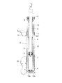
図1は、本発明の1つの実施形態であるストラット式流体圧緩衝器の全体構造を示したものである。同図において、1は、後に詳述する有底のベースシェル、2は、ベースシェル1に納められたシリンダ、3は、シリンダ2に摺動可能に内装されたピストン、4は、ピストン3に一端部が連結されたピストンロッドであり、ピストンロッド4の他端部は、ベースシェル1およびシリンダ2の開口端部に共通に嵌装したロッドガイド5およびオイルシール6を挿通して外部へ延ばされている。シリンダ2内には流体(ここでは、油液)が封入されており、また、ピストン3には減衰力発生手段7が、シリンダ2の底部にはベースバルブ8がそれぞれ配設されている。前記した構成は、ツインチューブ式油圧緩衝器として一般的にみられるもので、ピストンロッド4の伸長、短縮に応じて油液が減衰力発生手段7、ベースバルブ8を流通することで、伸び行程および縮み行程の減衰力が発生し、ピストンロッド4の進入、退出分の油液はベースシェル1とシリンダ2との間のリザーバ9で補償される。したがって、ベースシェル1内に納められたシリンダ2、ピストン3、ピストンロッド4等の部品類は緩衝機構を構成する。
FIG. 1 shows the overall structure of a strut-type fluid pressure shock absorber according to one embodiment of the present invention. In the figure, 1 is a bottomed base shell, which will be described in detail later, 2 is a cylinder housed in the
上記した構成のストラット式流体圧緩衝器(ここでは、油圧緩衝器)は、そのベースシェル1の底部に車輪側のナックルに取付けられるブラケット(ナックルブラケット)10を嵌合固定すると共に、そのベースシェル3の上部側に車体との間に介装される懸架ばねを受けるスプリングシート11を嵌合固定して、実用に共される。
The strut type fluid pressure shock absorber (here, the hydraulic shock absorber) having the above-described structure is configured to fit and fix a bracket (knuckle bracket) 10 attached to a knuckle on the wheel side to the bottom of the
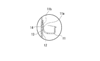
ここで、ベースシェル1は、図2にも示されるように、前記スプリングシート11の取付部より底部側が、ベースシェル1の全体形状を確定するシェル本体12の内面にそれより短尺の部分シェル13を密に嵌合させた二重管構造となっている。より詳しくは、シェル本体12と部分シェル13は共に底板部12a、13aを有する有底形状となっており、両者は、それぞれの底板部12aと13aとを密着させた状態で合わされている。また、シェル本体12は、スプリングシート11の取付部位に径方向の段差14を有しており、部分シェル13は、その開口端を前記段差14に当接させた状態でシェル本体12に合わされている。すなわち、部分シェル13は、その底板部13aをシェル本体12側の底板部12aに密着させ、その開口端をシェル本体12側の段差14に当接させることで、軸方向に拘束されている。前記段差14の高さは、ここでは部分シェル13の肉厚とほぼ同等に設定されており、これよりベースシェル1の内面は、その全長にわたってほぼ面一となっている。
Here, as shown in FIG. 2, the
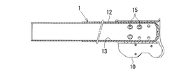
本実施形態において、上記ナックルブラケット10は、図3によく示されるように、その筒状部10aをベースシェル1と一体的に局部的に半径内方へ張出させた張出しカシメ部15によってベースシェル1に結合されている。この張出しカシメ部15を成形する加工法はメカニカルクリンチとして知られおり、ここでは、ナックルブラケット10の筒状部10aの周面に相対向して二対成形されている。一方、スプリングシート11は、図4によく示されるように、上記したシェル本体12の途中に形成した段差14に、その筒状部11aに形成した段部11bを着座させた状態でベースシェル1に嵌合保持されている。
In the present embodiment, as shown in FIG. 3, the
上記のように構成したストラット式油圧緩衝器は、そのベースシェル1の底部を下側、そのピストンロッド4の上端を上側として直立状態でサスペンションに組込まれ、この状態でベースシェル1には大きな曲げモーメントが入力される。この場合、ベースシェル1に入力される曲げモーメントは、スプリングシート11の取付部とナックルブラケット10の取付部との間で最も大きくなることが分かっている。本油圧緩衝器では、ベースシェル1の、スプリングシート取付部より底部側をシェル本体12と部分シェル13との二重管構造としているので、前記した曲げモーメントに十分に耐えるものとなる。
The strut type hydraulic shock absorber configured as described above is assembled into the suspension in an upright state with the bottom of the
ところで、前記したように同じ曲げモーメントが入力されたとき、単管よりも二重管構造の方が最大応力が小さくなることが分かっており、上記したようにベースシェル1を二重管構造にした場合も、この原理に従う。換言すると、要求される強度が同じであれば、ベースシェル1の二重管構造部分(シェル本体12と部分シェル13との嵌合部分)のトータルの肉厚を一体物のベースシェルより小さくできることになり、その分、ベースシェル1の軽量化が可能になる。一方、本油圧緩衝器においては、ベースシェル1の二重管構造部分が、スプリングシート取付部(段差14)より底部側に限定されていて、該段差14より上部側部分はシェル本体の単管となっているので、この単管部分では、全体を二重管構造とする場合よりも大幅に肉厚が減じ、その分、大幅な軽量化が可能になる。
By the way, when the same bending moment is input as described above, it is known that the maximum stress is smaller in the double pipe structure than in the single pipe, and the
すなわち、本油圧緩衝器では、ベースシェル1の、強度が要求される部分のみを二重管構造とし、その他の部分は単管構造としているので、全体を単管で構成した従来の一般的なベースシェルはもちろん、全体を二重管構造としたベースシェルに比べて大幅な軽量化が可能になる。なお、前記ベースシェル1の単管部分(シェル本体12)の肉厚は、ロッドガイド5およびオイルシール6の保持を維持できる程度の強度に見合う厚さとすれば十分である。
In other words, in this hydraulic shock absorber, only the portion of the
本実施形態においては特に、シェル本体12の途中に形成した段差14を利用してスプリングシート11をシェル本体12に嵌合固定しているので(図4)、一般的な油圧緩衝器のように溶接によりスプリングシートを固定したり、あるいはスプリングシートを係止するための膨出部をバルジ加工によりベースシェルに形成するなどの面倒な加工を省略できる。
Particularly in the present embodiment, the
以下、上記ベースシェル1を製造する方法を図5〜9に基いて説明する。
Hereinafter, a method for manufacturing the
ベースシェル1の製造に際しては、先ず、図5の上半分に示すように、シェル本体用の第1の管体20を用意し、該第1の管体20にその一端側からマンドレル21を所定深さまで挿入し、円筒状の第1のダイ22を第1のマンドレル21に沿って移動させて、スエージ加工(平行スエージ加工)を行う。このスエージ加工は、第1のダイ22により第1の管体20を絞りながら第1のマンドレル21との間でしごくように行い、これにより第1の管体20の一端側には縮径部20aが形成される。なお、このとき用いる第1のダイ22は、その進行方向の前端側にテーパ形状の導入部22aを有しており、この導入部22aによって第1のダイ22の円滑な移動が確保される。また、この導入部22aによって第1の管体20と前記縮径部20aとの境界部には、テーパ形状の段差部23が形成される。
When manufacturing the
次に、同じ図5の下半分に示すように、前記第1の管体20内に上記第1のマンドレル21の挿入側と反対側から第2のマンドレル24を挿入し、円筒状の第2のダイ25を上記第1の管体20の縮径部20aに沿って移動させて、前記段差部23の整形(角付け)を行う。第2のマンドレル24の先端部には、前記縮径部20aの内径と同じ外径を有する小径部24aが直角に起立する段差24bを介して形成されており、第2のマンドレル24は、その段差24aを前記段差部23に係合させる位置まで挿入される。このとき、第1のマンドレル21はその先端を第2のマンドレル21に突合せた状態を維持しながらわずか後退する。第2のダイ25は、縮径部20aの管端側から移動し、前記テーパ形状の段差部23を第2のマンドレル24の段差24bに対して押付けてしごき、これによって前記部分シェル13を位置決めするための段差14(図2)が形成される。
Next, as shown in the lower half of FIG. 5, a
次に、図6の上半分に示すように、部分シェル13用の第2の管体30を第3のマンドレル31と共に上記第1の管体20の未加工部分に挿入する。第3のマンドレル31には、第2の管体30の管端を支承する段差31aが形成されており、第2の管体20は、その先端が第1の管体20側の段差14に当接するまで挿入される。第1の管体20の未加工部分は、シェル本体12の内径よりわずか大きな内径を有しており、これによって両管体20と30との間にはわずかの隙間Sが形成され、結果として第1の管体20に対する第2の管体30の挿入は容易となる。
Next, as shown in the upper half of FIG. 6, the second
次に、図6の下半分に示すように、円筒状の第3のダイ32を第3のマンドレル31に沿って管端側から移動させて、スエージ加工(平行スエージ加工)を行う。このスエージ加工は、第3のダイ32により第1の管体20を絞りながら第3のマンドレル31との間でしごくように行い、これにより第1の管体20の未加工部が縮径されて、第2の管体30に密着する。なお、このとき用いる第3のダイ32は、第1のダイ22と実質同じもので、その進行方向の前端側には、移動を容易にするためのテーパ形状の導入部32aが設けられている。
Next, as shown in the lower half of FIG. 6, the cylindrical
なお、上記した各スエージ加工(図5,6)は、前記各ダイ22、25、32と断面形状が類似のロールを旋回させて行う回転しごき加工に代えてもよいものである。 Each swage process (FIGS. 5 and 6) may be replaced with a rotating ironing process performed by turning a roll having a cross-sectional shape similar to that of each of the dies 22, 25, and 32.
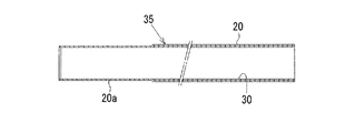
図7は、上記した一連の工程を終えた後のベースシェル素管35を示しており、この後は、図8に示すように、ベースシェル素管35の管端部をクロージング加工して、前記底板部12a、13aを一体的に成形し、これにてシェル本体12内の底部側に部分シェル13を密に嵌合させたベースシェル1が完成する。管端部のクロージング加工は、たとえば、特開2006−342725号公報に記載される方法を適用して行うことができる。この場合、内側の第2の管体30は、その先端を第1の管体20の段差14に当接させて前方への移動が規制されているので(図7)、ベースシェル素管35の管端部を一体的に口絞りして封口することができ、これにより前記底板部12a、13aは継ぎ目なしに成形される。なお、この底板部は、別体のベースキャップを溶接して形成してもよいことはもちろんである。
FIG. 7 shows the base
その後は、図9に示すように、ベースシェル1の底部側に前記したメカニカルクリンチを利用してナックルブラケット20を嵌合固定し、さらに段差14を利用してスプリングシート21を嵌合固定する。メカニカルクリンチは、たとえば、特開平2004−35318号公報に記載される方法を適用して行うことができる。もちろん、このナックルブラケット20の固定は、溶接等の他の方法によってもよいものである。
Thereafter, as shown in FIG. 9, the
1 ベースシェル
2 シリンダ(緩衝機構)
3 ピストン(緩衝機構)
4 ピストンロッド(緩衝機構)
10 ナックルブラケット
11 スプリングシート
12 シェル本体
12a シェル本体の底板部
13 部分シェル
13a 部分シェルの底板部
14 段差
1
3 Piston (buffer mechanism)
4 Piston rod (buffer mechanism)
DESCRIPTION OF
Claims (5)
Priority Applications (1)
| Application Number | Priority Date | Filing Date | Title |
|---|---|---|---|
| JP2008036472A JP2009192068A (en) | 2008-02-18 | 2008-02-18 | Strut type fluid pressure shock absorber and method for manufacturing base shell |
Applications Claiming Priority (1)
| Application Number | Priority Date | Filing Date | Title |
|---|---|---|---|
| JP2008036472A JP2009192068A (en) | 2008-02-18 | 2008-02-18 | Strut type fluid pressure shock absorber and method for manufacturing base shell |
Publications (1)
| Publication Number | Publication Date |
|---|---|
| JP2009192068A true JP2009192068A (en) | 2009-08-27 |
Family
ID=41074257
Family Applications (1)
| Application Number | Title | Priority Date | Filing Date |
|---|---|---|---|
| JP2008036472A Pending JP2009192068A (en) | 2008-02-18 | 2008-02-18 | Strut type fluid pressure shock absorber and method for manufacturing base shell |
Country Status (1)
| Country | Link |
|---|---|
| JP (1) | JP2009192068A (en) |
Cited By (2)
| Publication number | Priority date | Publication date | Assignee | Title |
|---|---|---|---|---|
| US8141227B2 (en) * | 2002-11-29 | 2012-03-27 | Kabushiki Kaisha Hitachi Seisakusho | Assembly of sheet materials, tube assembly, drawing method and tools for drawing |
| WO2019116876A1 (en) * | 2017-12-14 | 2019-06-20 | Kyb株式会社 | Outer shell and method for manufacturing same |
-
2008
- 2008-02-18 JP JP2008036472A patent/JP2009192068A/en active Pending
Cited By (3)
| Publication number | Priority date | Publication date | Assignee | Title |
|---|---|---|---|---|
| US8141227B2 (en) * | 2002-11-29 | 2012-03-27 | Kabushiki Kaisha Hitachi Seisakusho | Assembly of sheet materials, tube assembly, drawing method and tools for drawing |
| WO2019116876A1 (en) * | 2017-12-14 | 2019-06-20 | Kyb株式会社 | Outer shell and method for manufacturing same |
| JP2019105342A (en) * | 2017-12-14 | 2019-06-27 | Kyb株式会社 | Outer shell and manufacturing method of the same |
Similar Documents
| Publication | Publication Date | Title |
|---|---|---|
| JP5247808B2 (en) | Axle assembly for commercial vehicles and method of manufacturing this type of axle assembly | |
| CN101936356B (en) | Oil hydraulic cylinder | |
| CN112823252B (en) | Damper with two-piece housing | |
| JP5435190B2 (en) | Tube processing method and cylinder device manufacturing method | |
| US7810620B2 (en) | Bracket mounting structure and bracket mounting method | |
| JP2014057997A (en) | Tube with branch pipe, shock absorber, and method of manufacturing of them | |
| US20050218574A1 (en) | Hydraulic shock absorber | |
| CN107074056A (en) | It is fastened with the damper of latch plate and the method for latch plate to be fastened to damper | |
| US20120024647A1 (en) | Cylinder apparatus, method for manufacturing the same, and shock absorber | |
| WO2019065131A1 (en) | Front fork and method for manufacturing front fork | |
| JPWO2023067941A5 (en) | ||
| JP2009192068A (en) | Strut type fluid pressure shock absorber and method for manufacturing base shell | |
| JP2007321864A (en) | Damping force adjustment type hydraulic shock absorber | |
| JP3813782B2 (en) | Vehicle shock absorber sealing device | |
| DE19755039A1 (en) | Motor vehicle shock absorber of piston cylinder and pressure accumulator | |
| CN112930272A (en) | Damper with integral base | |
| JP6255249B2 (en) | shock absorber | |
| GB2050561A (en) | Outer Tube of Telescopic Shock Absorber | |
| JP2008223825A (en) | Shock absorber | |
| CN106369100A (en) | Automobile back shock absorber and connection process thereof | |
| JP2004232696A (en) | Hydraulic shock absorber | |
| JP2005016721A (en) | Single cylinder type damper | |
| JP6533026B1 (en) | Shock absorber | |
| JP2007092891A (en) | Rod structure of cylindrical hydraulic shock absorber | |
| JP2001311444A (en) | Hydraulic shock absorber |
Legal Events
| Date | Code | Title | Description |
|---|---|---|---|
| A711 | Notification of change in applicant |
Effective date: 20090907 Free format text: JAPANESE INTERMEDIATE CODE: A712 |
|
| RD03 | Notification of appointment of power of attorney |
Free format text: JAPANESE INTERMEDIATE CODE: A7423 Effective date: 20090907 |