JP2009190471A - Air conditioner for vehicle - Google Patents
Air conditioner for vehicle Download PDFInfo
- Publication number
- JP2009190471A JP2009190471A JP2008030947A JP2008030947A JP2009190471A JP 2009190471 A JP2009190471 A JP 2009190471A JP 2008030947 A JP2008030947 A JP 2008030947A JP 2008030947 A JP2008030947 A JP 2008030947A JP 2009190471 A JP2009190471 A JP 2009190471A
- Authority
- JP
- Japan
- Prior art keywords
- air
- vehicle
- blower
- air conditioner
- auxiliary blower
- Prior art date
- Legal status (The legal status is an assumption and is not a legal conclusion. Google has not performed a legal analysis and makes no representation as to the accuracy of the status listed.)
- Pending
Links
Images


Landscapes
- Air-Conditioning For Vehicles (AREA)
Abstract
Description
本発明は、車両の車室内空調を行う車両用空調装置に関するものである。 The present invention relates to a vehicle air conditioner that performs air conditioning in a vehicle interior of a vehicle.
下記の特許文献1〜4には、少なくとも車室内前席側空間と後席側空間との2つの空調ゾーンへ空調風を吹き出し、後席側に吹き出す空調風の風量を増加させる補助送風機を、空調ユニットの下方、もしくは車両後方側に一体的に備える車両用空調装置が開示されている。また、同様の補助送風機を、運転席と助手席との間に配置されるセンターコンソール内に備える車両用空調装置が知られている。
しかしながら、上記した従来技術において、補助送風機を空調ユニットに一体的に備える構成では、補助送風機が作動することによる振動が、空調ユニットに伝わり、更に空調ユニットが取り付けられているリーンフォースに伝わり、更にリーンフォースに取り付けられているステアリングにまで振動が伝わることで、運転者に不快感を与えてしまうという問題点がある。 However, in the above-described conventional technology, in the configuration in which the auxiliary blower is integrally provided in the air conditioning unit, vibration due to the operation of the auxiliary blower is transmitted to the air conditioning unit, and further transmitted to the lean force to which the air conditioning unit is attached. There is a problem that the driver feels uncomfortable because the vibration is transmitted to the steering attached to the lean force.
また、補助送風機をセンターコンソール内に備える構成では、乗員が座席周りでジュースなどをこぼした場合に送風モータにまでかかる可能性があり、送風モータがショートして発煙や故障を引き起こす虞がある。また、センターコンソールは、乗員が肘掛けとしても使うため、補助送風機が作動することによる振動が乗員にまで伝わり、乗員に不快感を与えてしまうという問題点がある。 Further, in the configuration in which the auxiliary blower is provided in the center console, when the occupant spills juice or the like around the seat, the blower motor may reach the blower motor, and the blower motor may be short-circuited to cause smoke or failure. Further, since the center console is also used as an armrest by the occupant, the vibration caused by the operation of the auxiliary blower is transmitted to the occupant, which causes discomfort to the occupant.
本発明は、このような従来の技術に存在する問題点に着目して成されたものであり、その目的は、補助送風機が作動することによる振動が乗員に伝わって、乗員に不快感を与えることのない車両用空調装置を提供することにある。 The present invention has been made paying attention to such problems existing in the prior art. The purpose of the present invention is to transmit vibrations to the occupant due to the operation of the auxiliary blower, and to make the occupant feel uncomfortable. An object of the present invention is to provide a vehicular air conditioner that never happens.
また、本発明の他の目的は、乗員が座席周りでジュースなどをこぼした場合でも、補助送風機にはかかりにくく、送風機モータがショートして発煙や故障を引き起こすことのない車両用空調装置を提供することにある。 Another object of the present invention is to provide a vehicle air conditioner that is unlikely to be applied to the auxiliary blower even when a passenger spills juice around the seat, and the blower motor is short-circuited to cause no smoke or malfunction. There is to do.
本発明は上記目的を達成するために、下記の技術的手段を採用する。すなわち、請求項1に記載の発明では、車両のインストルメントパネル(7)内に配設した空調ユニット(2)と、一端を空調ユニット(2)に接続し、他端を車両の左右方向略中央から前席乗員へ向けて空調風を吹き出す前席センターフェイス吹出口(29)に接続して空調風の通路となるセンターフェイスダクト(27)と、センターフェイスダクト(27)から分岐し、先端を車室内後席側の吹出口である後席フェイス吹出口(35)に接続して空調風の通路となる後席用ダクト(32、34)と、後席用ダクト(32、34)に設けられて車室内後席側に吹き出す空調風の風量を増加させる補助送風機(33)とを備える車両用空調装置において、
補助送風機(33)の送風ケース(331)は、空調ユニット(2)の空調ケース(10)とは別体で構成されるとともに、補助送風機(33)は、インストルメントパネル(7)内で空調ユニット(2)の車両後方側に隣接配置されていることを特徴としている。
In order to achieve the above object, the present invention employs the following technical means. That is, in the first aspect of the invention, the air conditioning unit (2) disposed in the instrument panel (7) of the vehicle, one end connected to the air conditioning unit (2), and the other end substantially in the left-right direction of the vehicle. A center face duct (27) that is connected to a front seat center face outlet (29) that blows conditioned air toward the front seat occupant from the center and serves as an air conditioned air passage, and branches from the center face duct (27) Are connected to a rear seat face outlet (35), which is an outlet on the rear seat side of the vehicle interior, to the rear seat ducts (32, 34) and the rear seat ducts (32, 34) serving as air-conditioned air passages. In a vehicle air conditioner provided with an auxiliary blower (33) that is provided and increases the amount of air-conditioned air blown to the rear seat side of the vehicle interior,
The blower case (331) of the auxiliary blower (33) is configured separately from the air conditioning case (10) of the air conditioning unit (2), and the auxiliary blower (33) is air-conditioned in the instrument panel (7). The unit (2) is arranged adjacent to the vehicle rear side.
この請求項1に記載の発明によれば、補助送風機(33)が作動することによる振動が、空調ユニット(2)からリーンフォース(6D)を介して乗員が触れているステアリングに伝わったり、乗員が触れているセンターコンソール(9)に伝わったりするのを防ぐことができるため、乗員に不快感を与えることがない。 According to the first aspect of the present invention, the vibration caused by the operation of the auxiliary blower (33) is transmitted from the air conditioning unit (2) to the steering wheel touched by the occupant via the lean force (6D). Can be prevented from being transmitted to the center console (9) touching, so that the passengers are not uncomfortable.
また、乗員が座席(8D、8P)周りでジュースなどをこぼした場合でも、インストルメントパネル(7)内の補助送風機(33)にはかかりにくく、ファンモータ(333)がショートして発煙や故障を引き起こすことがない。また、補助送風機(33)をインストルメントパネル(7)内に配設することで、補助送風機(33)の作動音を乗員に聞こえにくくすることができる。 Even if the passenger spills juice around the seat (8D, 8P), the auxiliary blower (33) in the instrument panel (7) is not easily applied and the fan motor (333) is short-circuited, causing smoke or malfunction. Will not cause. Moreover, by arranging the auxiliary blower (33) in the instrument panel (7), it is possible to make it difficult for passengers to hear the operation sound of the auxiliary blower (33).
また、請求項2に記載の発明では、請求項1に記載の車両用空調装置において、補助送風機(33)の送風ケース(331)は、車両の床面(6A)に固定されていることを特徴としている。この請求項2に記載の発明によれば、ゴムブッシュなどを介して、補助送風機(33)を堅牢な床面(6A)に固定することにより、補助送風機(33)の作動時の振動を他の構造体に伝えにくい構造とすることができる。
Moreover, in invention of
また、請求項3に記載の発明では、請求項1または2に記載の車両用空調装置において、補助送風機(33)は、扁平な送風ケース(331)内に扁平な遠心式多翼ファン(332)を配置して、その回転軸方向にて扁平に構成したものであり、回転軸が車両の略上下方向となるように補助送風機(33)が車両に配設されていることを特徴としている。
In the invention according to claim 3, in the vehicle air conditioner according to
また、請求項4に記載の発明では、請求項1または2に記載の車両用空調装置において、補助送風機(33)は、扁平な送風ケース(331)内に扁平な遠心式多翼ファン(332)を配置して、その回転軸方向にて扁平に構成したものであり、回転軸が車両の略左右方向となるように補助送風機(33)が車両に配設されていることを特徴としている。
Moreover, in invention of
これら請求項3または4に記載の発明によれば、補助送風機(33)の車両上下方向での高さ寸法、もしくは車両左右方向での幅寸法(W)を小型にすることができ、車両への搭載性を向上させることができる。なお、特許請求の範囲および上記各手段に記載の括弧内の符号は、後述する実施形態に記載の具体的手段との対応関係を示す一例である。 According to the inventions of the third and fourth aspects, the height dimension of the auxiliary blower (33) in the vertical direction of the vehicle or the width dimension (W) in the horizontal direction of the vehicle can be reduced. Can be improved. In addition, the code | symbol in the parenthesis as described in a claim and said each means is an example which shows a corresponding relationship with the specific means as described in embodiment mentioned later.
(第1実施形態)
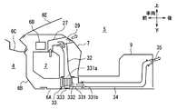
以下、本発明の第1実施形態について図1〜3を用いて詳細に説明する。図1は、本発明の第1実施形態における車両用空調装置1の構成を示す模式図であり、図2は、図1の車両用空調装置1の車両への搭載状態を示す平面模式図、図3は、図2中のIII−III断面図である。
(First embodiment)
Hereinafter, a first embodiment of the present invention will be described in detail with reference to FIGS. FIG. 1 is a schematic diagram showing a configuration of a vehicle air conditioner 1 according to a first embodiment of the present invention, and FIG. 2 is a schematic plan view showing a mounting state of the vehicle air conditioner 1 of FIG. 3 is a cross-sectional view taken along the line III-III in FIG.
図1に示すように、本実施形態の車両用空調装置1は、空調ユニット2と後席送風ユニット3とを有して構成されている。空調ユニット2は、車両の車室内に空調風を導くための空気通路11を形成する空調ケース10、この空調ケース10内に空気流れを発生させる遠心式のフロントブロワ20、空調ケース10内を流れる空気を冷却して車室内を冷房するためのエバポレータ(蒸発器)17、および空調ケース10内を流れる空気を加熱して車室内を暖房するためのヒータコア(温水加熱器)19などから構成されている。
As shown in FIG. 1, the vehicle air conditioner 1 of the present embodiment includes an
空調ユニット2は、図2に示すように、車両の車室5内前方側のインストルメントパネル(以下、インパネと略す)7内の略中央に配設され、フロントブロワ20は助手席8Pの前方部分に配置されている。なお、エンジンルーム4と車室5とは、ダッシュパネル6Bおよびカウル6C(図3参照)で区画されている。
As shown in FIG. 2, the
フロントブロワ20の最も風流れ上流側は、吸込口切替箱(内外気切替箱)を構成する部分であり、車室内空気(内気)を取り入れる内気吸込口14、および車室外空気(外気)を取り入れる外気吸込口15を有している。さらに、内気吸込口14および外気吸込口15の内側には、内外気(吸込口)切替ドア16が回動自在に取り付けられている。この内外気切替ドア16は、サーボモータなどの図示しないアクチュエータによって駆動され、吸込ロモードを内気循環モード、外気導入モードなどに切り替える。なお、内外気切替ドア16は、吸込口切替箱と共に内外気切替手段を構成する。
The most upstream side of the wind flow of the
また、フロントブロワ20は、空調ケース10と一体的に構成されたスクロールケースに回転自在に収容された遠心式多翼(シロッコ)ファン12、およびこの遠心式多翼ファン12を回転駆動するブロワモータ13を有している。そして、ブロワモータ13は、図示しないブロワ駆動回路を介して印加されるブロワ電圧に基づいて、遠心式多翼ファン12の回転速度、つまりは送風量が制御される。
The
空気通路11内であってフロントブロワ20の下流側には、内部を流通する冷媒との熱交換により空調風を冷却するエバポレータ17が配設されている。エバポレータ17は、冷媒が循環する図示しない冷凍サイクルの一部を構成する。その冷凍サイクルは、車両走行用のエンジンにベルト駆動されて冷媒を圧縮する圧縮機、圧縮された冷媒を凝縮液化させる凝縮器、凝縮液化された冷媒を気液分離して液冷媒のみを下流に流す受液器、液冷媒を減圧膨張させる膨張弁、減圧膨張された冷媒を蒸発気化させるエバポレータ17、およびこれらを環状に接続する冷媒配管などから構成されている。
An
エバポレータ17は、空気通路11を全面塞ぐようにして空調ケース10内に配設され、自身を通過する空気を冷却する空気冷却作用、および自身を通過する空気を除湿する空気除湿作用を行う室内熱交換器である。換言すると、エバポレータ17は、圧縮機の作動により空調風を冷却、除湿する冷却用熱交換器である。
The
エバポレータ17の空気流れ下流側には、エアミックスドア18が回動自在に配設されており、そのエアミックスドア18のさらに下流側には、空気通路11を部分的に塞ぐようにヒータコア19が配設されている。ヒータコア19は、エンジン冷却水が循環する図示しない冷却水回路の一部を構成する。
An
冷却水回路は、図示しないウォータポンプにより、エンジンのウォータジャケットで暖められた冷却水を循環させる回路であり、ラジエータ、サーモスタットおよびヒータコア19を有している。このヒータコア19は、内部にエンジンを冷却した冷却水が流れ、この冷却水を暖房用熱源としての熱交換により、エバポレータ17で冷却された空気を加熱する。
The cooling water circuit is a circuit that circulates the cooling water heated by the water jacket of the engine by a water pump (not shown), and has a radiator, a thermostat, and a
ヒータコア19の上方には、ヒータコア19を迂回して空気を流す冷風バイパス通路21が形成されており、空調ケース10の内部に、ヒータコア19を迂回する冷風側通路と、ヒータコア19を通過する温風側通路とを形成している。エアミックスドア18は、サーボモータなどの図示しないアクチュエータに駆動され、その停止位置によって、ヒータコア19を通過する空気量とヒータコア19を迂回する空気量との割合を調節して、車室内へ吹き出す空気の吹出温度を調節する吹出温度調節手段として働く。
Above the
空調ケース10内の冷風バイパス通路21および温風側通路の下流側には混合空間が形成され、冷風バイパス通路21からの冷風と温風側通路からの温風とが混合されて以下の各開口部に供給される。空調ケース10の最も風流れ下流側は、吹出口切替箱を構成する部分で、デフロスタ開口部22、フェイス開口部23、フット開口部24およびサイドフェイス開口部31が形成されている。
A mixed space is formed on the downstream side of the cold
デフロスタ開口部22は、デフロスタドア(吹出モード切替ドア)30によって開閉され、フェイス開口部23は、フェイスドア(吹出モード切替ドア)25によって開閉され、フット開口部24は、フットドア(吹出モード切替ドア)26によって開閉される。
The
なお、サイドフェイス開口部31にはサイドフェイスダクト28が接続され、その他端はインパネ7の左右側部に設けられた図示しないサイドフェイス吹出口に接続され、車室内前席乗員の頭胸部に向けて主に冷風を吹き出す。そして、車室内のサイドフェイス吹出口に設けられた手動のルーバーにより、吹出モードに関係なく乗員が開閉するようになっている。
A
空調ケース10内の3枚の吹出モード切替ドア25、26、30は、回動自在に取り付けられており、サーボモータなどの図示しないアクチュエータにより駆動されて、吹出口モードをフェイスモード、バイレベルモード、フットモード、フットデフロスタモードまたはデフロスタモードのいずれかに切り替える。
The three blowing
具体的には、吹出モードがフェイスモードのときには、フェイス開口部23が全開となり、デフロスタ開口部22およびフット開口部24が全閉となる。バイレベルモードのときには、フェイス開口部23とフット開口部24とが略半開で、デフロスタ開口部22が全閉となる。フットモードのときには、フット開口部24が略8割開、デフロスタ開口部22が略2割開で、フェイス開口部23が全閉となる。
Specifically, when the blowing mode is the face mode, the
フットデフロスタモードのときには、フット開口部24が略6割開、デフロスタ開口部22が略4割開で少なくとも全吹出風量の1/3以上に設定され、フェイス開口部23が全閉となる。デフロスタモードのときには、デフロスタ開口部22が全開となり、フェイス開口部23およびフット開口部24が全閉となる。なお、3枚の吹出モード切替ドア25、26、30は、吹出口切替箱と共に吹出口切替手段を構成する。
In the foot defroster mode, the
そして、デフロスタ開口部22には、図示しないデフロスタダクトが接続され、このデフロスタダクトの最下流端には、車両の前面窓ガラス6E(図3参照)の内面に向けて主に温風を吹き出すデフロスタ吹出口が開口している。また、フット開口部24には、図示しないフットダクトが接続され、このフットダクトの最下流端には、車室内前席の乗員の足元に向けて主に温風を吹き出すフット吹出口が開口している。
A defroster duct (not shown) is connected to the
なお、フェイス開口部23には、空調ケース10とは別体に形成されたセンターフェイスダクト27が接続されている。センターフェイスダクト27の空気流れ下流端側は、車室内前席乗員の頭胸部に向けて主に冷風を吹き出すセンターフェイス吹出口(前席センターフェイス吹出口)29に接続されている。センターフェイス吹出口29は、インパネ7の中央部近傍に設けられている。なお、制御系の構成および作動については、説明を省略する。
Note that a
次に、後席送風ユニット3について説明する。センターフェイスダクト27からは、センターフェイスダクト27を通過する空調風の一部を、車室内後席乗員の頭胸部に向けて吹き出すための後席用ダクトの一部として、分岐ダクト32が分岐されている(図3参照)。なお、分岐ダクト32は、フェイス開口部23よりも下流に設けられている。
Next, the rear seat blower unit 3 will be described. A
そして、分岐ダクト32の他端には、後席側に吹き出す空調風の風量を増加させるアシストブロワ(補助送風機)33が設けられている。このアシストブロワ33は、図3に示すように、扁平なスクロールケース(送風ケース)331内に、扁平な遠心式多翼(シロッコ)ファン332を配置して、その遠心式多翼ファン332を回転駆動するファンモータ333を含めて、その回転軸方向にて扁平に構成したものである。
The other end of the
このアシストブロワ33は、図2に示すように、空調ユニット2とは別体で構成されており、インパネ7内で空調ユニット2の車両後方側に隣接配置され、車両の床面6A(図3参照)に図示しないゴムブッシュなどを介して固定されている。なお、本実施形態では、その回転軸が車両の略上下方向に向けた姿勢で配設されている。
As shown in FIG. 2, the
そして、スクロールケース331の吸入口331aに分岐ダクト32の他端が接続され、センターフェイスダクト27を通過する空調風の一部を吸入するとともに、スクロールケース331の吐出口331bには、後席用ダクトの一部としての延長ダクト34が接続されている。この延長ダクト34は、図2に示すように、車室内前側で運転席8Dと助手席8Pとの間に配設されるセンターコンソール9内に配設され、その他端は、センターコンソール9上部の車両後方側に設けられたリアフェイス吹出口35に接続されている。
The other end of the
アシストブロワ33は、本空調装置1の作動を制御している図示しない制御装置によって作動制御され、ファンモータ333に印加されるアシストブロワ電圧に基づいて、所定の回転数で回転するようになっている。そして、上記構成による車両用空調装置1の吹出モードがフェイスモードで作動されるときには、センターフェイスダクト27内を通過する空調風の一部が、後席送風ユニット3側へ配風されて、リアフェイス吹出口35から後席乗員の頭胸部へ向けて空調風が吹き出される。
The
このとき、リアフェイス吹出口35からの吹出風量を充分確保するために、アシストブロワ33を作動させてリアフェイス風量を増加する。アシストブロワ33は、分岐ダクト32とセンターフェイスダクト27とを介して空調ユニット2に接続されているため、アシストブロワ33が作動することによる振動が空調ユニット2に伝わりにくくなっている。これにより、アシストブロワ33の振動が空調ユニット2→リーンフォース6D→ステアリングと伝わって運転者に不快感を与えることが防げる。
At this time, in order to ensure a sufficient amount of air blown from the rear
次に、本実施形態の特徴と、その効果について述べる。アシストブロワ33のスクロールケース331は、空調ユニット2の空調ケース10とは別体で構成されるとともに、アシストブロワ33は、インパネ7内で空調ユニット2の車両後方側に隣接配置されている。これによれば、アシストブロワ33が作動することによる振動が、空調ユニット2からリーンフォース6Dを介して乗員が触れているステアリングに伝わったり、乗員が触れているセンターコンソール9に伝わったりするのを防ぐことができるため、乗員に不快感を与えることがない。
Next, the features and effects of this embodiment will be described. The
また、乗員が座席8D、8P周りでジュースなどをこぼした場合でも、インパネ7内のアシストブロワ33にはかかりにくく、ファンモータ333がショートして発煙や故障を引き起こすことがない。また、アシストブロワ33をインパネ7内に配設することで、アシストブロワ33の作動音を乗員に聞こえにくくすることができる。
Further, even if the occupant spills juice around the
また、アシストブロワ33のスクロールケース331は、車両の床面6Aに固定されている。これによれば、ゴムブッシュなどを介して、アシストブロワ33を堅牢な床面6Aに固定することにより、アシストブロワ33の作動時の振動を他の構造体に伝えにくい構造とすることができる。
The
また、アシストブロワ33は、扁平なスクロールケース331内に扁平な遠心式多翼ファン332を配置して、その回転軸方向にて扁平に構成したものであり、回転軸が車両の略上下方向となるようにアシストブロワ33が車両に配設されている。これによれば、アシストブロワ33の車両上下方向での高さ寸法を小型にすることができ、車両への搭載性を向上させることができる。
The
(第2実施形態)
次に、本発明の第2実施形態について、図4および5を用いて説明する。図4は、上述した第1実施形態の図3に対応した本発明の第2実施形態における断面図であり、図5は、図4中のV視図である。なお、本実施形態においては、上述した第1実施形態と同一の構成要素には同一の符号を付して説明を省略し、異なる構成および特徴について説明する。
(Second Embodiment)
Next, a second embodiment of the present invention will be described with reference to FIGS. FIG. 4 is a cross-sectional view of the second embodiment of the present invention corresponding to FIG. 3 of the first embodiment described above, and FIG. 5 is a V view in FIG. In the present embodiment, the same components as those in the first embodiment described above are denoted by the same reference numerals, description thereof is omitted, and different configurations and features will be described.
本実施形態では、図4および5に示すように、上述した扁平なアシストブロワ33が、床面6Aに立てた状態で、図示しないゴムブッシュなどを介して床面6Aに固定されており、その回転軸方向が車両の略左右方向に向けた姿勢で配設されている。これによれば、アシストブロワ33の車両左右方向での幅寸法Wを小型にすることができ、車両への搭載性を向上させることができる。
In this embodiment, as shown in FIGS. 4 and 5, the above-described
(その他の実施形態)
本発明は上述した実施形態にのみ限定されるものではなく、次のように変形または拡張することができる。例えば、上述の実施形態では、左右独立コントロールタイプの空調装置ではなかったが、左右独立コントロールタイプの空調装置に適用しても良い。この場合、複数のセンターフェイスダクトが合流する合流地点より下流側にアシストブロワ33を設けることで、アシストブロワ33を一つ設けるだけで良く、コストを抑えることができる。
(Other embodiments)
The present invention is not limited to the above-described embodiments, and can be modified or expanded as follows. For example, in the above-described embodiment, the air conditioner is not a left / right independent control type air conditioner, but may be applied to a left / right independent control type air conditioner. In this case, by providing the
1…車両用空調装置
2…空調ユニット
6A…車両の床面
7…インストルメントパネル
10…空調ケース
27…センターフェイスダクト
29…センターフェイス吹出口(前席センターフェイス吹出口)
32…分岐ダクト(後席用ダクト)
33…アシストブロワ(補助送風機)
34…延長ダクト(後席用ダクト)
35…リアフェイス吹出口
331…スクロールケース(送風ケース)
332…遠心式多翼ファン
DESCRIPTION OF SYMBOLS 1 ...
32 ... Branch duct (rear seat duct)
33 ... Assist blower (auxiliary blower)
34 ... Extension duct (rear seat duct)
35 ... Rear face
332 ... Centrifugal multi-blade fan
Claims (4)
一端を前記空調ユニット(2)に接続し、他端を車両の左右方向略中央から前席乗員へ向けて空調風を吹き出す前席センターフェイス吹出口(29)に接続して前記空調風の通路となるセンターフェイスダクト(27)と、
前記センターフェイスダクト(27)から分岐し、先端を車室内後席側の吹出口である後席フェイス吹出口(35)に接続して前記空調風の通路となる後席用ダクト(32、34)と、
前記後席用ダクト(32、34)に設けられて前記車室内後席側に吹き出す前記空調風の風量を増加させる補助送風機(33)とを備える車両用空調装置において、
前記補助送風機(33)の送風ケース(331)は、前記空調ユニット(2)の空調ケース(10)とは別体で構成されるとともに、前記補助送風機(33)は、前記インストルメントパネル(7)内で前記空調ユニット(2)の車両後方側に隣接配置されていることを特徴とする車両用空調装置。 An air conditioning unit (2) disposed in an instrument panel (7) of the vehicle;
One end is connected to the air conditioning unit (2), and the other end is connected to the front seat center face outlet (29) for blowing the conditioned air from the substantially horizontal center of the vehicle toward the front seat occupant. The center face duct (27),
Rear seat ducts (32, 34) branched from the center face duct (27) and connected to the rear seat face air outlet (35), which is an air outlet on the rear seat side in the vehicle interior, to serve as the air-conditioned air passage. )When,
A vehicle air conditioner comprising: an auxiliary blower (33) provided in the rear seat ducts (32, 34) and configured to increase an air volume of the conditioned air blown toward the rear seat side of the vehicle interior;
The blower case (331) of the auxiliary blower (33) is configured separately from the air conditioning case (10) of the air conditioning unit (2), and the auxiliary blower (33) is configured of the instrument panel (7). ), The vehicle air conditioner is disposed adjacent to the vehicle rear side of the air conditioning unit (2).
Priority Applications (1)
| Application Number | Priority Date | Filing Date | Title |
|---|---|---|---|
| JP2008030947A JP2009190471A (en) | 2008-02-12 | 2008-02-12 | Air conditioner for vehicle |
Applications Claiming Priority (1)
| Application Number | Priority Date | Filing Date | Title |
|---|---|---|---|
| JP2008030947A JP2009190471A (en) | 2008-02-12 | 2008-02-12 | Air conditioner for vehicle |
Publications (1)
| Publication Number | Publication Date |
|---|---|
| JP2009190471A true JP2009190471A (en) | 2009-08-27 |
Family
ID=41072894
Family Applications (1)
| Application Number | Title | Priority Date | Filing Date |
|---|---|---|---|
| JP2008030947A Pending JP2009190471A (en) | 2008-02-12 | 2008-02-12 | Air conditioner for vehicle |
Country Status (1)
| Country | Link |
|---|---|
| JP (1) | JP2009190471A (en) |
Cited By (4)
| Publication number | Priority date | Publication date | Assignee | Title |
|---|---|---|---|---|
| JP2012131308A (en) * | 2010-12-21 | 2012-07-12 | Nissan Motor Co Ltd | Blower for vehicle |
| CN103052518A (en) * | 2010-08-19 | 2013-04-17 | 株式会社京滨 | Air conditioning system for vehicle |
| KR20140109093A (en) * | 2013-03-05 | 2014-09-15 | 한라비스테온공조 주식회사 | Air conditioning system for automotive vehicles |
| DE102014217123A1 (en) | 2013-08-28 | 2015-03-05 | Suzuki Motor Corporation | Ventilation ducts structure |
Citations (6)
| Publication number | Priority date | Publication date | Assignee | Title |
|---|---|---|---|---|
| JPS6277216A (en) * | 1985-09-30 | 1987-04-09 | Nippon Denso Co Ltd | Regenerative type heating apparatus for vehicle |
| JPS62173207U (en) * | 1986-04-25 | 1987-11-04 | ||
| JP2001171333A (en) * | 1999-12-16 | 2001-06-26 | Denso Corp | Vehicle air conditioner |
| JP2002347432A (en) * | 2001-05-24 | 2002-12-04 | Denso Corp | Air-conditioning device for vehicle |
| JP2004161059A (en) * | 2002-11-11 | 2004-06-10 | Denso Corp | Air-conditioner for vehicle |
| JP2005199978A (en) * | 2003-12-15 | 2005-07-28 | Denso Corp | Vehicular air-conditioner |
-
2008
- 2008-02-12 JP JP2008030947A patent/JP2009190471A/en active Pending
Patent Citations (6)
| Publication number | Priority date | Publication date | Assignee | Title |
|---|---|---|---|---|
| JPS6277216A (en) * | 1985-09-30 | 1987-04-09 | Nippon Denso Co Ltd | Regenerative type heating apparatus for vehicle |
| JPS62173207U (en) * | 1986-04-25 | 1987-11-04 | ||
| JP2001171333A (en) * | 1999-12-16 | 2001-06-26 | Denso Corp | Vehicle air conditioner |
| JP2002347432A (en) * | 2001-05-24 | 2002-12-04 | Denso Corp | Air-conditioning device for vehicle |
| JP2004161059A (en) * | 2002-11-11 | 2004-06-10 | Denso Corp | Air-conditioner for vehicle |
| JP2005199978A (en) * | 2003-12-15 | 2005-07-28 | Denso Corp | Vehicular air-conditioner |
Cited By (7)
| Publication number | Priority date | Publication date | Assignee | Title |
|---|---|---|---|---|
| CN103052518A (en) * | 2010-08-19 | 2013-04-17 | 株式会社京滨 | Air conditioning system for vehicle |
| CN103052518B (en) * | 2010-08-19 | 2015-05-20 | 株式会社京滨 | Air conditioning system for vehicle |
| JP2012131308A (en) * | 2010-12-21 | 2012-07-12 | Nissan Motor Co Ltd | Blower for vehicle |
| KR20140109093A (en) * | 2013-03-05 | 2014-09-15 | 한라비스테온공조 주식회사 | Air conditioning system for automotive vehicles |
| KR101978423B1 (en) * | 2013-03-05 | 2019-05-14 | 한온시스템 주식회사 | Air conditioning system for automotive vehicles |
| DE102014217123A1 (en) | 2013-08-28 | 2015-03-05 | Suzuki Motor Corporation | Ventilation ducts structure |
| DE102014217123B4 (en) | 2013-08-28 | 2018-03-29 | Suzuki Motor Corporation | Ventilation ducts structure |
Similar Documents
| Publication | Publication Date | Title |
|---|---|---|
| JP5556619B2 (en) | Air conditioner for vehicles | |
| JP4432992B2 (en) | Air conditioner for vehicles | |
| JP3804152B2 (en) | Air conditioner for vehicles | |
| JP2005112297A (en) | Air conditioner for vehicle | |
| JP2005199978A (en) | Vehicular air-conditioner | |
| JPH10230734A (en) | Air-conditioner for vehicle | |
| JP2007131072A (en) | Air-conditioner for vehicle | |
| JP2014180985A (en) | Vehicle air conditioning system | |
| JP2000326721A (en) | Air conditioning unit and vehicular air conditioner | |
| JP2008149866A (en) | Vehicular air conditioner | |
| JP2009190471A (en) | Air conditioner for vehicle | |
| JP5012758B2 (en) | Air conditioner for vehicles | |
| JP2007131137A (en) | Car air conditioner | |
| JP3791126B2 (en) | Air conditioner for vehicles | |
| JP2010006136A (en) | Vehicular safety device | |
| JP2006001378A (en) | Air conditioner for vehicle | |
| JP4075627B2 (en) | Air conditioner for vehicles | |
| JPH10166838A (en) | Vehicular air conditioner | |
| JP2005306166A (en) | Air-conditioner for vehicle | |
| JP2006056451A (en) | Vehicular air-conditioning system | |
| JP4600211B2 (en) | Air conditioner for vehicles | |
| JP2019098770A (en) | Air conditioning system | |
| JP4492517B2 (en) | Air conditioner for vehicles | |
| JPH10109516A (en) | Airconditioner for vehicular rear seat | |
| JP2008030594A (en) | Air conditioner for bus |
Legal Events
| Date | Code | Title | Description |
|---|---|---|---|
| A621 | Written request for application examination |
Free format text: JAPANESE INTERMEDIATE CODE: A621 Effective date: 20100331 |
|
| A977 | Report on retrieval |
Free format text: JAPANESE INTERMEDIATE CODE: A971007 Effective date: 20111005 |
|
| A131 | Notification of reasons for refusal |
Effective date: 20111018 Free format text: JAPANESE INTERMEDIATE CODE: A131 |
|
| A02 | Decision of refusal |
Free format text: JAPANESE INTERMEDIATE CODE: A02 Effective date: 20120306 |