JP2009189403A - Liquid level control device of bathtub - Google Patents
Liquid level control device of bathtub Download PDFInfo
- Publication number
- JP2009189403A JP2009189403A JP2008030446A JP2008030446A JP2009189403A JP 2009189403 A JP2009189403 A JP 2009189403A JP 2008030446 A JP2008030446 A JP 2008030446A JP 2008030446 A JP2008030446 A JP 2008030446A JP 2009189403 A JP2009189403 A JP 2009189403A
- Authority
- JP
- Japan
- Prior art keywords
- liquid level
- bathtub
- detection electrode
- screw member
- control device
- Prior art date
- Legal status (The legal status is an assumption and is not a legal conclusion. Google has not performed a legal analysis and makes no representation as to the accuracy of the status listed.)
- Granted
Links
Images


Abstract
Description
本発明は浴槽内の液位を制御する浴槽の液位制御装置に係り、特に、構成を簡略化させるとともに浴槽としての使い勝手を向上させることができるように工夫したものに関する。 The present invention relates to a liquid level control device for a bathtub that controls the liquid level in the bathtub, and more particularly, to a device that is devised so as to simplify the configuration and improve the usability as a bathtub.
浴槽には給水管が接続されていて、該給水管には電磁開閉弁が介挿されている。又、浴槽内には液位検出用の棒状の電極が複数本設置されている。例えば、所定の長さに調整された液位高検出用電極棒、液位低検出用電極棒、コモン用電極棒が浴槽内に設置されている。それら液位高検出用電極棒、液位低検出用電極棒、コモン用電極棒からの信号は制御装置に入力されるようになっている。制御装置はそれら液位高検出用電極棒、液位低検出用電極棒、コモン用電極棒からの信号に基づいて「液位高」、「液位低」を検出し、それによって、電磁開閉弁の開閉を制御するものである。すなわち、「液位低」を検出した場合には電磁開閉弁を開放して給水を行う。一方、「液位高」を検出した場合には、電磁開閉弁を閉じて給水を停止するものである。 A water supply pipe is connected to the bathtub, and an electromagnetic on-off valve is inserted in the water supply pipe. A plurality of bar-shaped electrodes for detecting the liquid level are installed in the bathtub. For example, a liquid level high detection electrode bar, a liquid level low detection electrode bar, and a common electrode bar adjusted to a predetermined length are installed in the bathtub. Signals from the liquid level high detection electrode bar, the liquid level low detection electrode bar, and the common electrode bar are input to the control device. The control device detects "liquid level high" and "liquid level low" based on the signals from these liquid level high detection electrode bar, liquid level low detection electrode bar, and common electrode bar, thereby opening and closing the electromagnetic It controls the opening and closing of the valve. That is, when “low liquid level” is detected, the electromagnetic on-off valve is opened to supply water. On the other hand, when “high liquid level” is detected, the electromagnetic on-off valve is closed to stop water supply.
その他様々な電極構造によって浴槽内の液位を検出する装置が提案されている。
そのようなものの一例を開示するものとして、例えば、特許文献1がある。
As an example of disclosing such an example, there is Patent Document 1, for example.
上記従来の構成によると次のような問題があった。
まず、構成が複雑であって装置が大型化してしまうという問題があった。すなわち、従来の場合には、棒状の複数本の電極を浴槽内に浸漬させたり、或いは、特許文献1に示すように、浴槽の外部に比較的大掛かりな装置を設けなければならないからである。
又、浴槽内が狭くなってしまうとともに美観上も劣ってしまうという問題があった。特に、浴槽内に複数本の棒状の電極を浸漬させる場合には顕著であった。
The conventional configuration has the following problems.
First, there is a problem that the configuration is complicated and the apparatus becomes large. That is, in the conventional case, a plurality of rod-shaped electrodes must be immersed in the bathtub, or as shown in Patent Document 1, a relatively large device must be provided outside the bathtub.
In addition, there is a problem that the inside of the bathtub becomes narrow and the aesthetics are inferior. This was particularly noticeable when a plurality of rod-shaped electrodes were immersed in the bathtub.
本発明はこのような点に基づいてなされたものでその目的とするところは、装置の簡略化、小型化を図ることを可能にするとともに、浴槽内のスペースを有効に利用することを可能にした浴槽の液位制御装置を提供することにある。 The present invention has been made based on such points, and the object of the present invention is to enable simplification and miniaturization of the apparatus and to effectively use the space in the bathtub. Another object of the present invention is to provide a liquid level control device for a bathtub.
上記目的を達成するべく本願発明の請求項1による浴槽の液位制御装置は、浴槽の側面であって所定の高位に貫通した状態で取り付けられた液位高検出電極用ねじ部材と、上記浴槽の側面であって所定の低位に貫通した状態で取り付けられた液位低検出電極用ねじ部材と、上記液位高検出電極用ねじ部材と上記液位低検出電極用ねじ部材からの信号に基づいて上記浴槽内に液体を供給する供給弁の開閉を制御する制御手段と、を具備したことを特徴とするものである。
又、請求項2による浴槽の液位制御装置は、請求項1記載の浴槽の液位制御装置において、上記液位高検出電極用ねじ部材は2個設置されており、同様に上記液位低検出電極用ねじ部材も2個設置されていることを特徴とするものである。
又、請求項3による浴槽の液位制御装置は、請求項1又は請求項2記載の浴槽の液位制御装置において、上記液位高検出電極用ねじ部材と上記液位低検出電極用ねじ部材として化粧ねじ部材を使用していることを特徴とするものである。
又、請求項4による浴槽の液位制御装置は、請求項3記載の浴槽の液位制御装置において、上記化粧ねじ部材を浴槽の内側から外側に貫通・配置し、浴槽の外側に突出した上記化粧ねじ部材にケーブルを接続し、上記浴槽の内外に液封処理を施したものであることを特徴とするものである。
In order to achieve the above object, a liquid level control device for a bathtub according to claim 1 of the present invention comprises a screw member for a liquid level high detection electrode attached to a side surface of a bathtub and penetrating to a predetermined high level, and the bathtub A liquid level low detection electrode screw member attached in a state of penetrating to a predetermined low level, based on signals from the liquid level high detection electrode screw member and the liquid level low detection electrode screw member And a control means for controlling the opening and closing of the supply valve for supplying the liquid into the bathtub.
The bathtub liquid level control apparatus according to claim 2 is the bathtub liquid level control apparatus according to claim 1, wherein two screw members for the liquid level high detection electrode are installed, and similarly the liquid level control apparatus is low. Two detection electrode screw members are also provided.
According to a third aspect of the present invention, there is provided the bathtub liquid level control device according to the first or second aspect, wherein the liquid level high detection electrode screw member and the liquid level low detection electrode screw member are used. It is characterized by using a decorative screw member.
The bathtub liquid level control device according to claim 4 is the bath liquid level control device according to claim 3, wherein the decorative screw member is penetrated and arranged from the inside of the bathtub to the outside, and protruded to the outside of the bathtub. A cable is connected to the decorative screw member, and a liquid sealing process is performed on the inside and outside of the bathtub.
以上述べたように本願発明の請求項1による浴槽の液位制御装置によると、浴槽の側面であって所定の高位に貫通した状態で取り付けられた液位高検出電極用ねじ部材と、上記浴槽の側面であって所定の低位に貫通した状態で取り付けられた液位低検出電極用ねじ部材と、上記液位高検出電極用ねじ部材と上記液位低検出電極用ねじ部材からの信号に基づいて上記浴槽内に液体を供給する供給弁の開閉を制御する制御手段と、を具備した構成になっているので、例えば、棒状の電極を複数本使用した従来の構成に比べると、構成の簡略化と装置の小型化を図ることができるとともに浴槽内の空間の有効利用を図ることができる。
又、請求2記載の浴槽の液位制御装置は、請求項1記載の浴槽の液位制御装置において、上記液位高検出電極用ねじ部材は2個設置されており、同様に上記液位低検出電極用ねじ部材も2個設置されている構成になっているので、電極の数も多く、より顕著な効果を得ることができる。
又、請求項3による浴槽の液位制御装置は、請求項1又は請求項2記載の浴槽の液位制御装置において、上記液位高検出電極用ねじ部材と上記液位低検出電極用ねじ部材として化粧ねじ部材を使用している構成になっているので、構成の簡略化と装置の小型化という効果意外に美観上の点でも優れた効果を発揮することができる。
又、請求項4による浴槽の液位制御装置は、請求項3記載の浴槽の液位制御装置において、上記化粧ねじ部材を浴槽の内側から外側に貫通・配置し、浴槽の外側に突出した上記化粧ねじ部材にケーブルを接続し、上記浴槽の内外に液封処理を施したものであるので、浴槽の内側には化粧ねじ部材のねじ頭のみが突出することになるので、浴槽内における空間の有効利用を効果的に図ることができる。
As described above, according to the liquid level control device for a bathtub according to claim 1 of the present invention, the screw member for the liquid level high detection electrode attached in a state of penetrating to a predetermined high position on the side surface of the bathtub, and the bathtub A liquid level low detection electrode screw member attached in a state of penetrating to a predetermined low level, based on signals from the liquid level high detection electrode screw member and the liquid level low detection electrode screw member And a control means for controlling the opening and closing of the supply valve for supplying the liquid into the tub. For example, the configuration is simplified compared to the conventional configuration using a plurality of rod-shaped electrodes. And downsizing of the apparatus can be achieved, and the space in the bathtub can be effectively used.
Further, the liquid level control device for a bathtub according to claim 2 is the liquid level control device for a bathtub according to claim 1, wherein two screw members for the liquid level high detection electrode are installed, and similarly the liquid level control device is low. Since two detection electrode screw members are also installed, the number of electrodes is large, and a more remarkable effect can be obtained.
According to a third aspect of the present invention, there is provided the bathtub liquid level control device according to the first or second aspect, wherein the liquid level high detection electrode screw member and the liquid level low detection electrode screw member are used. Since the decorative screw member is used, the effect of simplification of the configuration and the miniaturization of the device can be achieved, and an excellent effect can be exhibited in terms of aesthetics.
The bathtub liquid level control device according to claim 4 is the bath liquid level control device according to claim 3, wherein the decorative screw member is penetrated and arranged from the inside of the bathtub to the outside, and protruded to the outside of the bathtub. Since the cable is connected to the decorative screw member and the inside and outside of the bathtub are liquid-sealed, only the screw head of the decorative screw member protrudes inside the bathtub. Effective use can be effectively achieved.
以下、図1乃至図6を参照して本発明の一実施の形態を説明する。図1に示すように、まず、室1があり、この室1の浴室3の床5上には浴槽7が据え付けられている。上記浴槽7の側壁9の所定位置には、一対の液位高検出電極用ねじ部材11、13と、一対の液位低検出電極用ねじ部材15、17が取り付けられている。上記一対の液位高検出電極用ねじ部材11、13によって所定の「液位高」を検出する。又、上記一対の液位低検出電極用ねじ部材15、17によって所定の「液位低」を検出する。
Hereinafter, an embodiment of the present invention will be described with reference to FIGS. As shown in FIG. 1, first, there is a room 1, and a
上記一対の液位高検出電極用ねじ部材11、13の内、液位高検出電極用ねじ部材11は上限ストップを検知するための上限ストップ水位センサであり、液位高検出電極用ねじ部材13は上部コモン用センサである。又、上記一対の液位低検出電極用ねじ部材15、17の内、液位低検出電極用ねじ部材15は下限ストップを検知するための下限ストップ水位センサであり、液位低検出電極用ねじ部材17は下部コモン用センサである。
Among the pair of liquid level high detection
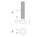
上記一対の液位高検出電極用ねじ部材11、13と、一対の液位低検出電極用ねじ部材15、17は、図2及び図3に拡大して示すように、浴槽7の側壁9に対して内側から外側に向けてねじ込まれている。そして、それら一対の液位高検出電極用ねじ部材11、13と、一対の液位低検出電極用ねじ部材15、17の先端は浴槽7の側壁9の外側に突出・配置されている。又、上記ねじ部材であるが、本実施の形態の場合には、特に、化粧ねじ部材を使用しているものであり、図4に示すような形状をなしている。
尚、図4は液位高検出電極用ねじ部材11を例に挙げて示しているが、その他の液位高検出電極用ねじ部材13と、一対の液位低検出電極用ねじ部材15、17も同様の形状をなしている。
The pair of liquid level high detection
4 shows the
上記液位高検出電極用ねじ部材11、13と、一対の液位低検出電極用ねじ部材15、17の取付構造について図3を参照して詳細に説明する。
尚、図3は上記液位高検出電極用ねじ部材11を例に挙げて示しているが、その他の上記液位高検出電極用ねじ部材13と、一対の液位低検出電極用ねじ部材15、17についても同様である。
まず、浴槽7の内壁と液位高検出電極用ねじ部材11のねじ頭11aとの間にはPEパッキン31が介挿されている。又、液位高検出電極用ねじ部材11の浴槽7の外側に突出した部位にはナット33、35が螺合されている。これらナット33、35の間にはケーブル37が金具39を介して接続されている。又、浴槽7の外側に突出した部位はコーキング材41によって処理されているものである。
尚、その他の液位高検出電極用ねじ部材13と、一対の液位低検出電極用ねじ部材15、17も上記したように同様の取付構造になっている。
又、図3では理解を容易にするために、液位高検出電極用ねじ部材11を若干ゆるめた状態にして、ねじ頭11aとPEパッキン31との間及びPEパッキン31と浴槽7との間に隙間をあけているが、実際には液位高検出電極用ねじ部材11を締め付けることによりそれら隙間はなくなるものである。
The mounting structure of the liquid level high detection
3 shows the
First, the
The other liquid level high detection
In FIG. 3, for easy understanding, the
上記一対の液位高検出電極用ねじ部材11、13と、一対の液位低検出電極用ねじ部材15、17からの信号は制御手段21に入力されるようになっている。又、上記浴槽7には防水用金具26を介して給水管23が接続されていてこの給水管23には電磁開閉弁25が介挿されている。
Signals from the pair of liquid level high detection
上記制御手段21は複数個のリレーやタイマー等から構成されたシーケンス回路として構成されていて、図5に示すような端子台51を備えている。既に説明した一対の液位高検出電極用ねじ部材11、13と、一対の液位低検出電極用ねじ部材15、17は、夫々リート線53、55、57を介して上記端子台51に接続されている。
但し、上記液位高検出電極用ねじ部材13と液位低検出電極用ねじ部材17については一本のリード線57に纏められた状態で上記端子台51に接続されるものである。
その他、AC100V電源59があり、このAC100V電源59はリード線61、63、65を介して上記端子台51に接続されている。又、上記電磁開閉弁25はリード線65、67、69を介して端子台51に接続されている。又、お湯張りスイッチ71があり、このお湯張りスイッチ71はリード線73、75、77を介して端子台51に接続されている。
The control means 21 is configured as a sequence circuit including a plurality of relays, timers, and the like, and includes a
However, the liquid level high detection
In addition, there is an AC
以上の構成を基にその作用を説明する。まず、空の浴槽7内に湯を張る場合には湯張りスイッチ71を押圧・操作する。それによって、電磁開閉弁25が開弁されて浴槽7内へのお湯張りが開始される。
尚、お湯張りスイッチ71が二回続けて押圧・操作された場合には電磁開閉弁25は閉弁されることになり、お湯張りは停止される。
The operation will be described based on the above configuration. First, when filling hot water in the
When the hot water filling switch 71 is pressed and operated twice in succession, the electromagnetic on-off
お湯張り開始後二分経過した時点で下限ストップ水位センサ、すなわち、液位低検出電極用ねじ部材15にまで浴槽7内の水位が達していない場合には電磁開閉弁25が閉弁されて浴槽7内へのお湯張りが停止される。又、お湯張り開始後10分経過した場合にも電磁開閉弁25が閉弁されて浴槽7内へのお湯張りが停止される。又、浴槽7内の水位が上限ストップ水位センサ、すなわち、液位高検出電極用ねじ部材11に達した場合にも、電磁開閉弁25が閉弁されて浴槽7内へのお湯張りが停止される。
When the water level in the
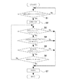
尚、本実施の形態の場合には上記制御を複数個のリレーとタイマー等からなるシーケンス回路によって実現する構成になっているが、これをソフト的に実行することも可能である。それを図6を参照して説明する。 In the present embodiment, the above control is realized by a sequence circuit composed of a plurality of relays and timers, but this can also be executed in software. This will be described with reference to FIG.
図6は情報処理の内容を示すフローチャートである。まず、ステップS1において、お湯張りスイッチ71が押されたか否かが判別される。お湯張りスイッチ71が押圧・操作されたと判別された場合にはステップS2に移行してお湯張りが開始される。これに対して、お湯張りスイッチ71が押圧・操作されていないと判別された場合には同判別が繰り返し実行される。 FIG. 6 is a flowchart showing the contents of information processing. First, in step S1, it is determined whether or not the hot water filling switch 71 has been pressed. If it is determined that the hot water filling switch 71 has been pressed and operated, the process proceeds to step S2 and hot water filling is started. On the other hand, when it is determined that the hot water filling switch 71 is not pressed and operated, the same determination is repeatedly performed.
次に、ステップS3に移行して、お湯張りスイッチ71が二回押されたか否かが判別される。お湯張りスイッチ71が二回押されていると判別された場合には、ステップS7に移行して給水が停止される。お湯張りスイッチ71が二回押されていないと判別された場合には、ステップS4に移行する。このステップS4においては、お湯張り開始後二分以内に下限水位センサ15に水位が達したか否かが判別される。お湯張り開始後二分以内に下限水位センサ15に水位が達していないと判別された場合には、ステップS7に移行して給水が停止される。これに対して、お湯張り開始後二分以内に下限水位センサ15に水位が達していると判別された場合にはステップS5に移行する。
Next, the process proceeds to step S3, where it is determined whether or not the hot water filling switch 71 has been pressed twice. When it is determined that the hot water filling switch 71 is pressed twice, the process proceeds to step S7, and water supply is stopped. If it is determined that the hot water filling switch 71 is not pressed twice, the process proceeds to step S4. In step S4, it is determined whether or not the water level has reached the lower limit
ステップS5においては、お湯張り開始後10分が経過しているか否かが判別される。お湯張り開始後10分が経過していると判別された場合にはステップS7に移行して給水が停止される。お湯張り開始後10分が経過していないと判別された場合にはステップS6に移行する。このステップS6においては、水位が上限水位センサ11に達しているか否かが判別される。水位が上限水位センサ11に達していると判別された場合にはステップS7に移行して給水が停止される。これに対して、水位が上限水位センサ11に達していないと判別された場合には、ステップS3に戻って同様の処理が繰り返されることになる。
In step S5, it is determined whether 10 minutes have elapsed since the start of hot water filling. When it is determined that 10 minutes have passed since the start of hot water filling, the process proceeds to step S7 and water supply is stopped. If it is determined that 10 minutes have not passed since the start of hot water filling, the process proceeds to step S6. In step S6, it is determined whether or not the water level has reached the upper limit
以上本実施の形態によると次のような効果を奏することができる。
まず、液位高検出用電極と液位低検出用電極として、上記液位高検出電極用ねじ部材11、13と、一対の液位低検出電極用ねじ部材15、17といったねじ部材を使用してこれを浴槽に取り付けるように構成しているので、例えば、棒状の電極を複数本使用した従来の構成に比べると、構成の簡略化と装置の小型化を図ることができるとともに浴槽内の空間の有効利用を図ることができる。
特に、この実施の形態の場合には、「液位高」、「液位低」用として夫々2個ずつの電極を使用しているので、上記効果はより顕著なものとなる。
又、上記液位高検出用電極と上記液位低検出用電極として、ねじ部材の中でも特に化粧ねじ部材を使用しているので、構成の簡略化と装置の小型化という効果意外に美観上の点でも優れた効果を発揮することができる。
又、上記一対の液位高検出電極用ねじ部材11、13と、一対の液位低検出電極用ねじ部材15、17を浴槽7の内側から外側に向けてねじ込むようにしているので、浴槽7の内側にはねじ頭11a、13a、15a、17aのみが突出することになり、浴槽7内の空間を有効に利用することが可能になる。
As described above, according to the present embodiment, the following effects can be obtained.
First, as the liquid level high detection electrode and the liquid level low detection electrode, screw members such as the liquid level high detection
In particular, in the case of this embodiment, since two electrodes are respectively used for “high liquid level” and “low liquid level”, the above-described effect becomes more remarkable.
Also, as the liquid level high detection electrode and the liquid level low detection electrode, a decorative screw member is used, among other screw members. An excellent effect can also be exhibited in terms.
The pair of liquid level high detection
尚、本発明は前記一実施の形態に限定されるものではない。
例えば、電極の個数は4個に限定されることはなく、3個の場合、5個以上の場合も想定される。
又、制御の内容についてはあくまで一例を示したものであり、それに限定されるようなものではない。
その他、図示した構成はあくまで一例である。
The present invention is not limited to the one embodiment.
For example, the number of electrodes is not limited to four, and the number of electrodes is assumed to be five or more.
Further, the content of the control is merely an example, and is not limited thereto.
In addition, the illustrated configuration is merely an example.
本発明は浴槽内の液位を制御する浴槽の液位制御装置に係り、特に、構成を簡略化させるとともに浴槽としての使い勝手を向上させることができるように工夫したものに関し、例えば、ホテルや旅館等において使用される浴槽用として好適である。 The present invention relates to a liquid level control device for a bathtub that controls the liquid level in the bathtub, and particularly relates to a device that has been devised so as to simplify the configuration and improve the usability as a bathtub. It is suitable for a bathtub used in, etc.
1 室
3 浴室
5 床
7 浴槽
9 側壁
11 液位高検出電極用ねじ部材
13 液位高検出電極用ねじ部材
15 液位低検出用電極
17 液位低検出用電極
21 制御手段
23 給水管
25 電磁開閉弁
1 room 3
Claims (4)
上記浴槽の側面であって所定の低位に貫通した状態で取り付けられた液位低検出電極用ねじ部材と、
上記液位高検出電極用ねじ部材と上記液位低検出電極用ねじ部材からの信号に基づいて上記浴槽内に液体を供給する供給弁の開閉を制御する制御手段と、
を具備したことを特徴とする浴槽の液位制御装置。 A screw member for a liquid level high detection electrode which is attached to the side surface of the bathtub and penetrates to a predetermined high level;
A screw member for a liquid level low detection electrode attached in a state of penetrating to a predetermined low side on the side of the bathtub,
Control means for controlling opening and closing of a supply valve for supplying liquid into the bathtub based on signals from the screw member for the liquid level high detection electrode and the screw member for the liquid level low detection electrode;
A liquid level control device for a bathtub.
上記液位高検出電極用ねじ部材は2個設置されており、同様に上記液位低検出電極用ねじ部材も2個設置されていることを特徴とする浴槽の液位制御装置。 In the bathtub liquid level control device according to claim 1,
Two liquid level high detection electrode screw members are installed, and similarly two liquid level low detection electrode screw members are also installed.
上記液位高検出電極用ねじ部材と上記液位低検出電極用ねじ部材として化粧ねじ部材を使用していることを特徴とする浴槽の液位制御装置。 In the liquid level control apparatus of the bathtub of Claim 1 or Claim 2,
A liquid level control apparatus for a bathtub, wherein a decorative screw member is used as the liquid level high detection electrode screw member and the liquid level low detection electrode screw member.
上記化粧ねじ部材を浴槽の内側から外側に貫通・配置し、浴槽の外側に突出した上記化粧ねじ部材にケーブルを接続し、上記浴槽の内外に液封処理を施したものであることを特徴とする浴槽の液位制御装置。 In the liquid level control apparatus of the bathtub of Claim 3,
The decorative screw member penetrates and is arranged from the inside to the outside of the bathtub, a cable is connected to the decorative screw member protruding to the outside of the bathtub, and a liquid seal treatment is applied to the inside and outside of the bathtub. Liquid level control device for bathtub.
Priority Applications (1)
| Application Number | Priority Date | Filing Date | Title |
|---|---|---|---|
| JP2008030446A JP5063397B2 (en) | 2008-02-12 | 2008-02-12 | Bath level control device |
Applications Claiming Priority (1)
| Application Number | Priority Date | Filing Date | Title |
|---|---|---|---|
| JP2008030446A JP5063397B2 (en) | 2008-02-12 | 2008-02-12 | Bath level control device |
Publications (2)
| Publication Number | Publication Date |
|---|---|
| JP2009189403A true JP2009189403A (en) | 2009-08-27 |
| JP5063397B2 JP5063397B2 (en) | 2012-10-31 |
Family
ID=41072043
Family Applications (1)
| Application Number | Title | Priority Date | Filing Date |
|---|---|---|---|
| JP2008030446A Active JP5063397B2 (en) | 2008-02-12 | 2008-02-12 | Bath level control device |
Country Status (1)
| Country | Link |
|---|---|
| JP (1) | JP5063397B2 (en) |
Citations (5)
| Publication number | Priority date | Publication date | Assignee | Title |
|---|---|---|---|---|
| JPH0814653A (en) * | 1994-06-30 | 1996-01-19 | Tokyo Gas Co Ltd | Bath tub system |
| JPH11311562A (en) * | 1998-04-27 | 1999-11-09 | Wako:Kk | Water level sensor |
| JP2001289695A (en) * | 2000-04-03 | 2001-10-19 | Oizumi Seisakusho:Kk | Combined sensor for sensing water-level and water- temperature |
| JP2004275515A (en) * | 2003-03-17 | 2004-10-07 | Noritz Corp | Electrode unit for water tank attachment |
| WO2006019273A1 (en) * | 2004-08-18 | 2006-02-23 | Doo Doo Energy Technology Co., Ltd. | A bathtub remote control system |
-
2008
- 2008-02-12 JP JP2008030446A patent/JP5063397B2/en active Active
Patent Citations (5)
| Publication number | Priority date | Publication date | Assignee | Title |
|---|---|---|---|---|
| JPH0814653A (en) * | 1994-06-30 | 1996-01-19 | Tokyo Gas Co Ltd | Bath tub system |
| JPH11311562A (en) * | 1998-04-27 | 1999-11-09 | Wako:Kk | Water level sensor |
| JP2001289695A (en) * | 2000-04-03 | 2001-10-19 | Oizumi Seisakusho:Kk | Combined sensor for sensing water-level and water- temperature |
| JP2004275515A (en) * | 2003-03-17 | 2004-10-07 | Noritz Corp | Electrode unit for water tank attachment |
| WO2006019273A1 (en) * | 2004-08-18 | 2006-02-23 | Doo Doo Energy Technology Co., Ltd. | A bathtub remote control system |
Also Published As
| Publication number | Publication date |
|---|---|
| JP5063397B2 (en) | 2012-10-31 |
Similar Documents
| Publication | Publication Date | Title |
|---|---|---|
| MY154395A (en) | System and method for water breakthrough detection intervention in a production well | |
| MX2008010382A (en) | Plumbing device wave control circuit. | |
| WO2005045335A3 (en) | Improved designs for filtration systems within appliances | |
| ATE396522T1 (en) | SEALED CONNECTION THROUGH A BULKHEAD AND ASSEMBLY METHOD | |
| ATE471297T1 (en) | METHOD FOR CLEANING POLYSILICON CRUSH | |
| WO2017098333A3 (en) | Automated animal washing systems | |
| JP5063397B2 (en) | Bath level control device | |
| WO2006074043A3 (en) | Method and apparatus for providing motion estimation with weight prediction | |
| EP1377772A4 (en) | Replaceable corrosion seal for threaded connections | |
| US20150159352A1 (en) | Manual and automatic integrated faucet | |
| WO2012159760A8 (en) | Screwed cable gland having a sleeve and a two-component sealing material | |
| KR101837936B1 (en) | Apparatus for producing sterilizing water using metallic ion | |
| CA2969340C (en) | Electronic drain closure system | |
| AU2003295862A8 (en) | Analysis of sulfate using conductometric end-point detection with suppression of cationic co-precipitation | |
| KR200408182Y1 (en) | Sensor for water supply system | |
| TW200728211A (en) | Electrolyzed water generation device and sink having the same | |
| JP2013206680A (en) | Kitchen remote control | |
| SI1806083T1 (en) | Bath and/or shower device | |
| CN105318093A (en) | Intelligent control faucet | |
| JP3896212B2 (en) | Electrolyzed water generator | |
| CN205037583U (en) | A prevent electric wall inlet tube for electric water heater | |
| DE502007002171D1 (en) | Flush-mounted cistern with variable water connection | |
| CN103325367A (en) | Water level controllable buzzer of semi-automatic washing machine | |
| JP2005030541A (en) | Water filling switching device | |
| CN104100750B (en) | A kind of nontoxic healthy water outlet port structure |
Legal Events
| Date | Code | Title | Description |
|---|---|---|---|
| A621 | Written request for application examination |
Free format text: JAPANESE INTERMEDIATE CODE: A621 Effective date: 20100817 |
|
| A977 | Report on retrieval |
Free format text: JAPANESE INTERMEDIATE CODE: A971007 Effective date: 20120216 |
|
| A131 | Notification of reasons for refusal |
Free format text: JAPANESE INTERMEDIATE CODE: A131 Effective date: 20120220 |
|
| A521 | Request for written amendment filed |
Free format text: JAPANESE INTERMEDIATE CODE: A523 Effective date: 20120419 |
|
| A131 | Notification of reasons for refusal |
Free format text: JAPANESE INTERMEDIATE CODE: A131 Effective date: 20120509 |
|
| A521 | Request for written amendment filed |
Free format text: JAPANESE INTERMEDIATE CODE: A523 Effective date: 20120709 |
|
| TRDD | Decision of grant or rejection written | ||
| A01 | Written decision to grant a patent or to grant a registration (utility model) |
Free format text: JAPANESE INTERMEDIATE CODE: A01 Effective date: 20120727 |
|
| A01 | Written decision to grant a patent or to grant a registration (utility model) |
Free format text: JAPANESE INTERMEDIATE CODE: A01 |
|
| A61 | First payment of annual fees (during grant procedure) |
Free format text: JAPANESE INTERMEDIATE CODE: A61 Effective date: 20120807 |
|
| R150 | Certificate of patent or registration of utility model |
Ref document number: 5063397 Country of ref document: JP Free format text: JAPANESE INTERMEDIATE CODE: R150 Free format text: JAPANESE INTERMEDIATE CODE: R150 |
|
| FPAY | Renewal fee payment (event date is renewal date of database) |
Free format text: PAYMENT UNTIL: 20150817 Year of fee payment: 3 |
|
| R250 | Receipt of annual fees |
Free format text: JAPANESE INTERMEDIATE CODE: R250 |
|
| R250 | Receipt of annual fees |
Free format text: JAPANESE INTERMEDIATE CODE: R250 |
|
| R250 | Receipt of annual fees |
Free format text: JAPANESE INTERMEDIATE CODE: R250 |
|
| R250 | Receipt of annual fees |
Free format text: JAPANESE INTERMEDIATE CODE: R250 |
|
| R250 | Receipt of annual fees |
Free format text: JAPANESE INTERMEDIATE CODE: R250 |
|
| R250 | Receipt of annual fees |
Free format text: JAPANESE INTERMEDIATE CODE: R250 |