JP2009183449A - Light source unit - Google Patents
Light source unit Download PDFInfo
- Publication number
- JP2009183449A JP2009183449A JP2008026291A JP2008026291A JP2009183449A JP 2009183449 A JP2009183449 A JP 2009183449A JP 2008026291 A JP2008026291 A JP 2008026291A JP 2008026291 A JP2008026291 A JP 2008026291A JP 2009183449 A JP2009183449 A JP 2009183449A
- Authority
- JP
- Japan
- Prior art keywords
- heat absorption
- absorption filter
- light source
- light
- optical path
- Prior art date
- Legal status (The legal status is an assumption and is not a legal conclusion. Google has not performed a legal analysis and makes no representation as to the accuracy of the status listed.)
- Pending
Links
Images


Abstract
Description
本発明は、熱吸収フィルタによって熱線をカットした上で照明光を照射する、内視鏡等に使用される光源装置に関する。 The present invention relates to a light source device used for an endoscope or the like that irradiates illumination light after cutting a heat ray by a heat absorption filter.
内視鏡光源装置には、キセノンランプやハロゲンランプ等の光源が設けられており、その光源からの光が、ライトガイドを介して体内へ照射され、体内を照明するための照明光として使用される。上記光源から出射される照明光は、熱線(赤外光)を含むので、そのままライトガイドに入射されると、内視鏡や体内へ熱的損傷を引き起こすおそれがある。そのため、光源からの照明光は、通常、熱吸収フィルタで熱線が吸収された上で、ライトガイドに入射される。 The endoscope light source device is provided with a light source such as a xenon lamp or a halogen lamp, and the light from the light source is irradiated into the body through a light guide and used as illumination light for illuminating the body. The Since the illumination light emitted from the light source includes heat rays (infrared light), if it enters the light guide as it is, it may cause thermal damage to the endoscope or the body. Therefore, the illumination light from the light source is normally incident on the light guide after the heat rays are absorbed by the heat absorption filter.
熱吸収フィルタは、照明光が照射される部分において発熱が生じ、照明光が照射される部分と、照明光が照射されない部分とでは温度差が発生する。照明光が照射され加熱された部分は熱膨張するので、発生した温度差によって、熱吸収フィルタに歪みが発生し、熱吸収フィルタに割れや亀裂等の破損が発生するおそれがある。近年、特にランプ性能が向上し、高輝度のランプが使用されることが多いので、熱吸収フィルタに割れ等が生じるおそれが高くなっている。 The heat absorption filter generates heat in the portion irradiated with the illumination light, and a temperature difference occurs between the portion irradiated with the illumination light and the portion not irradiated with the illumination light. Since the portion irradiated with the illumination light and heated is thermally expanded, the heat absorption filter may be distorted due to the generated temperature difference, and the heat absorption filter may be broken or broken. In recent years, lamp performance has been particularly improved, and high-intensity lamps are often used. Therefore, there is a high risk of cracks occurring in the heat absorption filter.
従来、例えば、特許文献1乃至3に記載されるように、熱吸収フィルタを予め分割しておき、分割されたフィルタ各々で発生する熱膨張量を抑え、フィルタ割れが生じにくくすることが知られている。
Conventionally, for example, as described in
また、例えば、特許文献4に記載されるように、熱吸収フィルタとして1枚の大きなフィルタを用意し、そのフィルタを常に回転させることによって、照明光が常に熱吸収フィルタの異なる位置に入射させるようにすることも知られている。このような構成によれば、熱吸収フィルタの一部に照明光が集中的に照射されなくなるので、フィルタの局所的な温度上昇が抑えられ、フィルタ破損の可能性が低下させられている。
しかしながら、特許文献1乃至3に記載される方法では、フィルタを分割することによるフィルタの性能低下が懸念され、さらに、光源の輝度が高くなると、予め分割しておいたフィルタ各々も加熱によってさらに破損しまうおそれもある。また、特許文献4の構成においても、常に1枚の熱吸収フィルタに照明光が照射され続けることとなるので、熱吸収フィルタの破損を完全に防ぐことは困難である。
However, in the methods described in
そこで、本発明は、上記問題点に鑑みて成されてものであり、熱吸収フィルタの破損をより確実に防止することが可能な光源装置を提供することを目的とする。 Therefore, the present invention has been made in view of the above problems, and an object of the present invention is to provide a light source device that can more reliably prevent the heat absorption filter from being damaged.
本発明に係る光源装置は、通常光を出射する主光源と、各々単独で通常光の光路に配置され、光路上に配置された1つの熱吸収フィルタによって通常光の熱線をカットし、かつ光路上に配置される熱吸収フィルタが1つの熱吸収フィルタから他の1つの熱吸収フィルタに切り替え可能である複数の熱吸収フィルタと、熱線がカットされた通常光が入射端から入射されて、その入射された通常光を伝送し、出射端から出射するライトガイドと、補助光を出射する補助光源とを備える。そして、光路上に配置される熱吸収フィルタが、1つの熱吸収フィルタから他の1つの熱吸収フィルタに切り替えられるとき、主光源からの通常光をライトガイドに入射されないようにすると共に、補助光を入射端を介してライトガイドに入射させることを特徴とする。 A light source device according to the present invention cuts the heat rays of normal light by a main light source that emits normal light, and a single heat absorption filter arranged on the optical path, each of which is independent of the normal light. A plurality of heat absorption filters whose heat absorption filters arranged on the road can be switched from one heat absorption filter to another heat absorption filter, and normal light from which heat rays have been cut are incident from the incident end. A light guide that transmits incident normal light and exits from the exit end and an auxiliary light source that emits auxiliary light are provided. When the heat absorption filter disposed on the optical path is switched from one heat absorption filter to another heat absorption filter, the normal light from the main light source is not incident on the light guide, and the auxiliary light Is incident on the light guide through the incident end.
上記熱吸収フィルタとしては、2つのフィルタが設けられても良いが、3以上のフィルタが設けられても良い。例えば、2つのフィルタが設けられる場合、一方のフィルタが光路上に配置し、他方のフィルタが光路から退避されることになる。また、3以上のフィルタが設けられる場合、1つのフィルタが光路上に配置し、その他の2以上のフィルタが光路から退避されることとなる。 Although two filters may be provided as the heat absorption filter, three or more filters may be provided. For example, when two filters are provided, one filter is disposed on the optical path and the other filter is retracted from the optical path. When three or more filters are provided, one filter is disposed on the optical path, and the other two or more filters are retracted from the optical path.
光源装置は、複数の熱吸収フィルタが装着されるフィルタ装着体と、フィルタ装着体を移動させる移動手段とをさらに備えていても良い。この場合、フィルタ装着体を移動させて、光路上に配置される熱吸収フィルタが、1つの熱吸収フィルタから他の1つの熱吸収フィルタに切り替えられる。また、フィルタ装着体は、回転軸を中心に回転するターレットであって、複数のフィルタは、回転軸を中心とする同一円上に装着されることが好ましい。 The light source device may further include a filter mounting body on which a plurality of heat absorption filters are mounted, and a moving unit that moves the filter mounting body. In this case, the filter mounting body is moved, and the heat absorption filter disposed on the optical path is switched from one heat absorption filter to another heat absorption filter. The filter mounting body is a turret that rotates about a rotation axis, and the plurality of filters are preferably mounted on the same circle about the rotation axis.
また、光路上に配置される熱吸収フィルタが、1つの熱吸収フィルタから他の熱吸収フィルタに切り替えられるとき、熱吸収フィルタに入射されない通常光を、フィルタ挿着体によって遮光して入射端から入射させないようにすることが好ましい。 Further, when the heat absorption filter disposed on the optical path is switched from one heat absorption filter to another heat absorption filter, the normal light that is not incident on the heat absorption filter is shielded by the filter insertion member from the incident end. It is preferable not to make it enter.
補助光源が光路上に配置されることによって、補助光が入射端に入射されると共に、通常光が補助光源によって遮光されることが好ましい。この場合例えば、補助光源が光路上に配置させることによって通常光が遮光された後、1つの熱吸収フィルタに代えて、他の熱吸収フィルタが光路上に配置される。補助光は、熱吸収フィルタを通過しないで入射端に入射されることが好ましい。 By arranging the auxiliary light source on the optical path, it is preferable that the auxiliary light is incident on the incident end and the normal light is blocked by the auxiliary light source. In this case, for example, after the normal light is blocked by arranging the auxiliary light source on the optical path, another heat absorbing filter is arranged on the optical path instead of one heat absorbing filter. The auxiliary light is preferably incident on the incident end without passing through the heat absorption filter.
好ましくは、光路上に配置された1つの熱吸収フィルタに破損の可能性があると判断された場合、光路上に配置される熱吸収フィルタが、1つの熱吸収フィルタから他の1つの熱吸収フィルタに切り替えられる。 Preferably, when it is determined that there is a possibility of damage to one heat absorption filter disposed on the optical path, the heat absorption filter disposed on the optical path is changed from one heat absorption filter to another heat absorption filter. Switch to filter.
また、光路上に配置された1つの熱吸収フィルタに破損の可能性があると判断されると共に、光路から退避されている他の1つの熱吸収フィルタに破損の可能性がないと判断された場合、光路上に配置される熱吸収フィルタが、1つの熱吸収フィルタから他の1つの熱吸収フィルタに切り替えられても良い。 Further, it was determined that one heat absorption filter disposed on the optical path may be damaged, and it was determined that there was no possibility of damage to the other one heat absorption filter retracted from the optical path. In this case, the heat absorption filter disposed on the optical path may be switched from one heat absorption filter to another heat absorption filter.
例えば、複数の熱吸収フィルタ全てが破損の可能性があると判断された場合、主光源からの通常光を複数の熱吸収フィルタ及びライトガイドに入射されないようにすると共に、補助光を入射端からライトガイドに入射させることが好ましい。 For example, when it is determined that all of the plurality of heat absorption filters may be damaged, normal light from the main light source is not incident on the plurality of heat absorption filters and the light guide, and auxiliary light is transmitted from the incident end. It is preferable to enter the light guide.
複数の熱吸収フィルタのうち少なくとも1つは、温度が検知され、その検知された温度が所定の温度以上であるとき、破損の可能性があると判断されることが好ましい。この場合例えば、複数の熱吸収フィルタのうち少なくとも1つの周辺部には、温度検知手段が配設されている。そして、その温度検知手段によって測定された周辺部の温度から、熱吸収フィルタの中心部の温度を推定し、その推定した温度を上記の検知された温度とする。 It is preferable that at least one of the plurality of heat absorption filters is detected as having a possibility of being damaged when the temperature is detected and the detected temperature is equal to or higher than a predetermined temperature. In this case, for example, a temperature detection unit is disposed in at least one peripheral portion of the plurality of heat absorption filters. And the temperature of the center part of a heat absorption filter is estimated from the temperature of the peripheral part measured by the temperature detection means, and let the estimated temperature be said detected temperature.
複数の熱吸収フィルタのうち少なくとも1つは、温度分布状況が検知され、その温度分布状況からフィルタの破損の可能性の有無が判断されても良い。また、光路上に配置された1つの熱吸収フィルタは、連続して通常光が入射される時間が所定時間以上なったときに破損の可能性があると判断されても良い。さらに、熱吸収フィルタの少なくとも1つは、通常光の累計の入射時間が所定時間以上となったとき、破損の可能性があると判断されても良い。 At least one of the plurality of heat absorption filters may detect a temperature distribution state and determine whether or not the filter may be damaged based on the temperature distribution state. Further, it may be determined that one heat absorption filter arranged on the optical path may be damaged when the time during which normal light is continuously incident exceeds a predetermined time. Further, it may be determined that at least one of the heat absorption filters may be damaged when the cumulative incident time of the normal light becomes a predetermined time or longer.
本発明に係る別の光源装置は、通常光を出射する主光源と、各々単独で通常光の光路に配置され、光路上に配置された1つの熱吸収フィルタによって通常光の熱線をカットし、かつ前記光路上に配置される熱吸収フィルタが1つの熱吸収フィルタから他の1つの熱吸収フィルタに切り替え可能である複数の熱吸収フィルタと、熱線がカットされた通常光が入射端から入射されて、その入射された通常光を伝送し、出射端から出射するライトガイドと、補助光を出射する補助光源とを備える。そして、光路上に配置された1つの熱吸収フィルタに破損の可能性があると判断された場合、光路上に配置される熱吸収フィルタが、その1つの熱吸収フィルタから他の1つの熱吸収フィルタに切り替えられる。また、複数の熱吸収フィルタ全てが破損の可能性があると判断された場合、主光源からの通常光を複数の熱吸収フィルタ及びライトガイドに入射されないようにすると共に、補助光を入射端を介してライトガイドに入射させることを特徴とする。 Another light source device according to the present invention cuts the heat rays of the normal light by a main light source that emits normal light, and each of them is arranged in the normal light optical path, and one heat absorption filter arranged on the optical path, And the heat absorption filter arrange | positioned on the said optical path is switchable from one heat absorption filter to another heat absorption filter, and the normal light from which the heat ray was cut enters from the incident end And a light guide that transmits the incident normal light and exits from the exit end, and an auxiliary light source that emits auxiliary light. When it is determined that there is a possibility of damage to one heat absorption filter disposed on the optical path, the heat absorption filter disposed on the optical path is absorbed by the one heat absorption filter from the other heat absorption filter. Switch to filter. In addition, when it is determined that there is a possibility that all of the plurality of heat absorption filters may be damaged, normal light from the main light source is not incident on the plurality of heat absorption filters and the light guide, and auxiliary light is input to the incident end. Through the light guide.
この場合、光路上に配置された1つの熱吸収フィルタに破損の可能性があると判断され、かつ光路から退避されている他の1つの熱吸収フィルタに破損の可能性がないと判断された場合に、光路上に配置される熱吸収フィルタが、1つの熱吸収フィルタから他の1つの熱吸収フィルタに切り替えられることが好ましい。 In this case, it is determined that there is a possibility of damage to one heat absorption filter disposed on the optical path, and it is determined that there is no possibility of damage to the other one heat absorption filter retracted from the optical path. In this case, it is preferable that the heat absorption filter disposed on the optical path is switched from one heat absorption filter to another heat absorption filter.
本発明によれば、1つの熱吸収フィルタに破損の可能性が生じると、破損の可能性のない別の熱吸収フィルタを光路上に配置させることで熱吸収フィルタの破損を防止することができる。また、そのフィルタ交換が行われている間、補助光による照明によって実質的にライトガイドに、照明光が入射されない時間を無くすことができる。 According to the present invention, when a possibility of breakage occurs in one heat absorption filter, it is possible to prevent breakage of the heat absorption filter by arranging another heat absorption filter having no possibility of breakage on the optical path. . Further, during the replacement of the filter, it is possible to substantially eliminate the time during which the illumination light is not incident on the light guide by illumination with the auxiliary light.
以下、本発明に係る実施形態について、図面を参照して説明する。
図1は、第1の実施形態に係る内視鏡システムの全体概略図である。図1に示すように、内視鏡システム10は、プロセッサ20と内視鏡11とを備える。プロセッサ20は、内視鏡11で得られた画像信号を処理するための装置として使用されると共に、主光源21及び補助光源41(図2参照)を備え、光源装置としても使用される。なお、主光源21及び補助光源41が設けられる光源装置は、画像信号を処理するためのプロセッサとは別体に設けられていても良い。
Hereinafter, embodiments according to the present invention will be described with reference to the drawings.
FIG. 1 is an overall schematic diagram of an endoscope system according to the first embodiment. As shown in FIG. 1, the
内視鏡11は、挿入部12と、挿入部12の一端に連結される操作部13と、プロセッサ20に対して着脱自在に接続されるコネクタ部17と、操作部13とコネクタ部17とを接続する接続可撓管14とを備える。
The
挿入部12は、体内に挿入させられて体内を観察するためのものであって、その先端部12Aには、撮像素子(不図示)が配設される。内視鏡11は、挿入部12からコネクタ部17まで内視鏡11の内部に挿入され、光ファイバーバンドルから構成されるライトガイド15を備える。ライトガイド15の一方の端部(出射端)は、先端部12Aに配置されると共に、ライトガイド15の他方の端部(入射端15A)は、コネクタ部17から外部に延出している。
The
コネクタ部17がプロセッサ20に接続されると、ライトガイド15の入射端15Aは、プロセッサ20のガイド受け部20Aを介してプロセッサ20内部に挿入される。プロセッサ20の内部において、入射端15Aは、後述する主光源21又は補助光源41(図2参照)に光学的に接続される。主光源21又は補助光源41から出射された照明光は、入射端15Aから入射され、ライトガイド15の内部を伝送して、出射端、すなわち先端部12Aから出射され、体内(被写体)に照射される。
When the
コネクタ部17にはビデオコネクタ18が設けられ、コネクタ部17がプロセッサ20に接続されると、ビデオコネクタ18がプロセッサ20のコネクタ受け部20Bに挿入される。
The
先端部12Aに配置された不図示の撮像素子は、照明光が照射された体内(被写体)を撮像して画像信号を生成する。その画像信号は、ビデオコネクタ18を介してプロセッサ20に入力される。画像信号は、プロセッサ20の信号処理部(不図示)において所定の画像処理が施された後、プロセッサ20に接続されたモニタ(不図示)に出力画像として表示される。
An imaging element (not shown) disposed at the
信号処理部で行われる画像処理のモードとしては、通常光モードと補助光モードとがある。挿入部12の先端部12Aから主光源21からの照明光(通常光)が出射される場合、通常光モードに設定され、画像信号は通常光に応じた画像処理が施される。また、補助光源41からの照明光(補助光)が先端部12Aから出射される場合、補助光モードに設定され、画像信号は補助光に応じた画像処理が施される。なお、補助光モードと通常光モードとでは、例えばホワイトバランス処理の方法が異なる。
As a mode of image processing performed in the signal processing unit, there are a normal light mode and an auxiliary light mode. When illumination light (normal light) from the main
図2は、プロセッサの内部を示すための側面図である。プロセッサ20内の光源(主光源)21は、例えば、ハロゲンランプ、キセノンランプ等から構成され、熱線(すなわち、赤外光)を含む通常光(例えば、白色光)を出射する。プロセッサ20内部において、主光源21とライトガイド15の入射端15Aの間における主光源21の光路L上には、主光源21側から順に、ターレット22、絞り23、及び集光レンズ24が配置される。絞り23は、モータ25に接続されており、その開度がモータ25によって調整される。絞り23は、ターレット22よりも主光源21側に配置されていても良い。また、集光レンズ24は省略されても良い。
FIG. 2 is a side view showing the inside of the processor. The light source (main light source) 21 in the
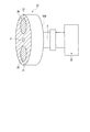
ターレット22は、図2、3から明らかなように、略円形のプレート状に形成されると共に、その中心に回転軸Xが設けられる。ターレット22はその背面22Bが主光源21の出射端に対向するように配置される。ターレット22の回転軸Xにはモータ33が接続されている。モータ33は、回転軸Xを中心にターレット22を回転させることができる。モータ33の動作は、マイコン等から構成されるモータ回転制御装置34によって制御される。
As is apparent from FIGS. 2 and 3, the
ターレット22には、回転軸Xを中心とする同一円上に第1及び第2の開口部35、36が穿設され、その開口部35、36内部それぞれに、第1及び第2の熱吸収フィルタ31、32が嵌め入れられて装着される。第1及び第2の開口部35、36(すなわち、第1及び第2の熱吸収フィルタ31、32)は、断面略円形に形成されており、回転軸Xを挟み込むように、回転軸Xを中心に対称的に配置される。第1及び第2の熱吸収フィルタ31、32は、入射された光の熱線(赤外光)をカットし、可視光を透過する熱吸収ガラス等によって構成される。ターレット22の回転軸Xは、光路Lの中心(光路中心LC)に対して平行であり、ターレット22(すなわち、第1及び第2の熱吸収フィルタ31、32)は、光路中心LCに対して直交する面に沿って移動される。
The
第1及び第2の熱吸収フィルタ31、32は、各々単独で通常光の光路Lに配置されるフィルタであって、いずれか一方の熱吸収フィルタが、光路L上に配置されると共に、他方の熱吸収フィルタが光路Lから退避させられている。光路L上に配置された一方の熱吸収フィルタは、そのフィルタの中心部が光路中心LCに位置されている。主光源21からの通常光は、光路L上に配置された一方の熱吸収フィルタに入射され、そのフィルタによって熱線(赤外光)がカットされ、その他の光がフィルタを透過する。フィルタを透過した通常光は、絞り23で光量が調整された後、集光レンズ24で集光されて、ライトガイド15の入射端15Aに入射される。
The first and second heat absorption filters 31 and 32 are each independently disposed in the optical path L of normal light, and either one of the heat absorption filters is disposed on the optical path L and the other The heat absorption filter is retracted from the optical path L. One heat absorption filter arranged on the optical path L has the center portion of the filter positioned at the optical path center LC. Normal light from the main
本実施形態では、ターレット22が回転されることにより、光路L上に配置される熱吸収フィルタが一方の熱吸収フィルタから他方の熱吸収フィルタに切り替えられる。そしてその切り替えられている間、主光源21からの通常光は、一部又は全部が、熱吸収フィルタに入射されなくなり、遮光性を有するターレット22に照射される。すなわち、フィルタ切り替え中に、熱吸収フィルタに入射されない一部又は全部の通常光は、ターレット22によって遮光され、ライトガイド15に入射しない。
In the present embodiment, when the
プロセッサ20の内部には、さらに温度センサ40及び補助光源41が設けられる。温度センサ40は、例えば公知の光センサであって、光路L上に配置される熱吸収フィルタの温度を検知することが可能である。温度センサ40は、例えば、熱吸収フィルタの背面(すなわち、主光源21側の面)であって、光路中心LCと熱吸収フィルタが交差する位置の温度を検知する。すなわち、温度センサ40は、光路L上に配置される一方の熱吸収フィルタの中心部の温度を検知する。
A
補助光源41は、LED等の発光体で構成されており、平行光である補助光を出射する。補助光は、通常光がライトガイド15に入射できないとき等に、その代わりに体内(被写体)を照明するための光であり、補助光の光量は主光源21の光量と同等かそれ未満である。補助光は、熱線(すなわち、赤外光)の含有量が、通常光に比べて低いため、熱線をカットせずにライトガイド15に入射しても、内視鏡11や体内へ熱的損傷を引き起こすおそれが低い。
The auxiliary
本実施形態における補助光源41は、プレート状に形成され、その前面41Fに発光体が取り付けられると共に、その背面41Bには反射膜が形成される。補助光源41は、モータ42に接続されており、モータ42によって、光路L上に挿入され、また光路Lから退避させられるように移動することが可能である。モータ42の動作は、モータ42に接続されたモータ制御装置43によって制御される。なお、図2は、補助光源41が光路L上に配置されたときの様子を示している。
The auxiliary
補助光源41は、光路L上に配置されるとき、集光レンズ24と入射端15Aの間に配置され、その前面41Fが入射端15Aに近接対向させられる。したがって、光路L上に配置された補助光源41の前面41Fから出射した補助光は、熱吸収フィルタを介さずに入射端15Aに直接入射される。また、補助光源41の背面41Bは、集光レンズ24(すなわち、主光源21側)に向けられ、これにより、主光源21から出射された通常光は、背面41Bの反射膜で反射される。したがって、光路L上に補助光源41が配置されているとき、主光源21からの通常光は、補助光源41によって、ライトガイド15に入射されないように遮光される。
When the auxiliary
図4、5は、本実施形態に係るプロセッサ20で行われるルーチンを説明するためのフローチャートである。以下、本フローチャートを用いて、プロセッサ20で行われるルーチンを説明する。
4 and 5 are flowcharts for explaining a routine performed by the
本ルーチンでは、主光源21の電源が投入されると、ステップS100で主光源21から通常光の出射が開始される。また、ターレット22及び補助光源41が初期状態の位置に配置され、すなわち、第1の熱吸収フィルタ31が光路L上に配置されると共に、補助光源41が光路Lから退避されている。これにより、ステップS100では、主光源21からの照明光が、第1の熱吸収フィルタ31、絞り23、及び集光レンズ24を介して、ライトガイドの入射端15Aに入射され、挿入部12の先端部12A(図1参照)から出射される。また、信号処理部の画像処理モードは、通常光モードに設定されており、撮像素子で生成された画像信号は、通常光モードで画像処理が行われて、モニタ上に出力される。
In this routine, when the main
次いで、S110では、温度センサ40によって、光路Lに配置される一方の熱吸収フィルタの温度が検知される。例えば、初期状態では、光路Lに配置されるフィルタは、第1の熱吸収フィルタ31であるので、温度センサ40によって第1の熱吸収フィルタ31の温度が検知される。なお、熱吸収フィルタは、その中心部が、光路中心LCに配置されるように光路L上に配置されているので、温度センサ40はフィルタの中心部の温度を検知する。
Next, in S110, the
次いで、ステップS120では、ステップS110で検知されたフィルタの温度が閾値(所定温度)以上であるか否かが判定される。ここで閾値は、任意に設定可能であるが、例えば、フィルタに破損が生じる温度である限界耐熱温度の50%程度の温度に設定される。ステップS120でフィルタの温度が、閾値未満であると判断された場合、その熱吸収フィルタは割れ等の破損が生じる可能性がないと判断され、光路L上にある熱吸収フィルタが、そのまま継続して光路L上に配置され続け、ステップS125に進む。ステップS125では、使用者からのスイッチ入力等による、照明光の消灯指示があったか否かが判定され、消灯指示があった場合、ステップS126で主光源21が消灯されて本ルーチンを終了する。一方、消灯指示がない場合、主光源21からの通常光が先端部12Aから継続して出射され、ステップS110に戻る。
Next, in step S120, it is determined whether or not the temperature of the filter detected in step S110 is equal to or higher than a threshold value (predetermined temperature). Here, the threshold value can be arbitrarily set. For example, the threshold value is set to a temperature of about 50% of the critical heat resistance temperature that is a temperature at which the filter is damaged. If it is determined in step S120 that the temperature of the filter is lower than the threshold value, it is determined that there is no possibility of breakage such as cracking in the heat absorption filter, and the heat absorption filter on the optical path L continues as it is. And continue to be arranged on the optical path L, and the process proceeds to step S125. In step S125, it is determined whether or not an illumination light extinguishing instruction has been given by a switch input or the like from the user. If there is an extinguishing instruction, the main
一方、ステップS120でフィルタの温度が、閾値以上であると判断された場合、光路L上にある熱吸収フィルタは割れ等の破損が生じる可能性があると判断され、図5に示すフィルタ切替動作(ステップS130〜S190)が行われる。 On the other hand, if it is determined in step S120 that the temperature of the filter is equal to or higher than the threshold value, it is determined that the heat absorption filter on the optical path L may be broken or the like, and the filter switching operation illustrated in FIG. (Steps S130 to S190) are performed.
ステップS130では、補助光源41の電源が投入されることによって、補助光源41の発光が開始され、その後、ステップS140で補助光源41が光路Lに挿入配置される。補助光源41が、光路L上に配置されると、背面41Bによって主光源21からの照明光が遮光され、主光源21からの照明光がライトガイド15に入射されないようになる。そして、入射端15Aには補助光源41からの補助光が入射され、通常光の代わりに補助光が先端部12Aから出射される。ステップS150では、画像処理モードが補助光モードに切り替えられ、撮像素子で生成された画像信号は、補助光モードに応じた画像処理が施された上でモニタに表示される。
In step S130, the auxiliary
ステップS160では、ターレット22が180°回転され、光路Lに配置されていた一方の熱吸収フィルタに代わって、光路Lから退避されていた他方の熱吸収フィルタが光路L上に配置される。なお、ターレット22が回転する間、主光源21からの通常光の一部又は全部は、熱吸収フィルタ31、32に入射されず、ターレット22に照射され、ターレット22によって遮光される。また、第1及び第2の熱吸収フィルタ31、32を透過するその他の通常光は、補助光源41の背面41Bにより遮光される。したがって、ターレット22が回転してフィルタが切り替えられる間、主光源21からの光がライトガイド15に入射されることはない。
In step S <b> 160, the
他方の熱吸収フィルタが光路L上に配置された後、ステップS170では、補助光源41が光路Lから退避され、補助光源41からの補助光がライトガイド15に入射されなくなる。これにより、主光源21からの通常光は、背面41Bによって遮光されなくなり、ライトガイド15に入射される。このとき、主光源21から出射した照明光は、ステップS160で新たに光路L上に配置された他方の熱吸収フィルタによって熱線がカットされた後、ライトガイド15に入射されることとなる。
After the other heat absorption filter is disposed on the optical path L, in step S170, the auxiliary
ステップS180では、退避された補助光源41の発光が停止された後、ステップS190では、画像処理のモードが通常光モードに切り替えられ、撮像素子で生成された画像信号に対して、通常光に応じた画像処理が行われることとなる。その後、図4に示すステップS110に戻って、光路L上に新たに配置された熱吸収フィルタの温度検出が行われる。そして、その温度が閾値を超えるまで、或いは消灯指示が出されるまで、ステップS110〜125において、主光源21からの照明光が入射端15Aに入射され続ける。
In step S180, after the light emission of the retracted auxiliary
以上のように、本実施形態では、光路L上に配置された一方の熱吸収フィルタ(例えば、第1の熱吸収フィルタ31)が、所定の温度に達した場合、光路L上に配置される熱吸収フィルタが、一方の熱吸収フィルタから、他方の熱吸収フィルタ(例えば、第2の熱吸収フィルタ32)に切り替えられる。したがって、光路Lに配置される熱吸収フィルタの過加熱が防止され、熱吸収フィルタの破損が防止される。 As described above, in the present embodiment, when one heat absorption filter (for example, the first heat absorption filter 31) arranged on the optical path L reaches a predetermined temperature, it is arranged on the optical path L. The heat absorption filter is switched from one heat absorption filter to the other heat absorption filter (for example, the second heat absorption filter 32). Therefore, overheating of the heat absorption filter disposed in the optical path L is prevented, and damage to the heat absorption filter is prevented.
また、光路L上に配置される熱吸収フィルタが、一方のフィルタから他方のフィルタに切り替えられている間、通常光の一部又は全部は、熱吸収フィルタに入射されなくなる。しかし、本実施形態では、そのように熱吸収フィルタに入射されない通常光は、ターレット22によって遮光され、ライトガイド15に入射されることはないので、内視鏡11や体内が熱損傷される虞はない。
Further, while the heat absorption filter disposed on the optical path L is switched from one filter to the other filter, part or all of the normal light is not incident on the heat absorption filter. However, in this embodiment, the normal light that is not incident on the heat absorption filter is shielded by the
また、本実施形態では、光路L上に配置される熱吸収フィルタが、一方から他方のフィルタに切り替えられている間、通常光に代わって補助光源41の補助光がライトガイドに入射される。熱吸収フィルタが切り替えられている間、主光源21からの光はライトガイド15に入射されなくなるが、本実施形態ではその間、上記補助光がライトガイドに入射されるので、被写体に照明光が照射されない時間を実質的に無くすことができる。
In the present embodiment, while the heat absorption filter disposed on the optical path L is switched from one to the other, the auxiliary light from the auxiliary
またフィルタが切り替えられている間、回転するターレット22の遮光によって、熱吸収フィルタを透過する通常光の光量は時間経過と共に変化するが、そのような光量が経時で変化する通常光は、補助光源41によって遮光され、ライトガイドには入射されない。したがって、被写体に照射される照明光の光量むらは、最小限に抑えることができる。
Further, while the filter is switched, the amount of normal light transmitted through the heat absorption filter changes with time due to the light shielding of the
なお、本実施形態では、ステップS110、S120において、フィルタ温度によってフィルタ破損の可能性の有無が検知されているが、異なる方法によってその可能性の有無が検知されても良い。例えば、光路L上に継続して配置される熱吸収フィルタに主光源21からの照明光が連続して入射される時間が、所定時間以上となったときに、光路L上にある熱吸収フィルタに破損の可能性があると検知しても良い。また、同一の熱吸収フィルタに入射される通常光の入射時間の累計が、所定時間以上となったときにフィルタ破損の可能性があると判断されても良い。また、内視鏡11或いはプロセッサ20において、所定のスイッチ操作があったときに、ステップS130〜S190のルーチンが実施され、光路Lに配置されるフィルタが切り替えられても良い。また、本実施形態における補助光源41は、上記態様の他、例えば主光源21が破損されて使用できなくなった場合にも使用される。
In the present embodiment, in steps S110 and S120, the possibility of filter breakage is detected based on the filter temperature. However, the presence or absence of such possibility may be detected by a different method. For example, when the time during which the illumination light from the main
図6〜8は、本発明の第2の実施形態を説明するための図である。以下、本実施形態について、第1の実施形態との相違点を説明する。 6-8 is a figure for demonstrating the 2nd Embodiment of this invention. Hereinafter, the difference between the present embodiment and the first embodiment will be described.
図6に示すように、本実施形態では、温度センサとして、第1及び第2の温度センサ40A、40Bが設けられる。第1の温度センサ40Aは、第1の実施形態と同様に、光路上に配置される一方の熱吸収フィルタの温度を検知するためのものである。第2の温度センサ40Bは、光路Lから退避された他方の熱吸収フィルタの温度を検出するためのものである。なお、第2の温度センサ40Bは、第1の温度センサ40Aと同様に、退避されたフィルタの中心部の温度を検知する。
As shown in FIG. 6, in the present embodiment, first and
図7、8は、第2の実施形態に係るプロセッサの動作を示すためのフローチャートである。本実施形態において、ステップS100〜120は第1の実施形態と同様に実施される。そして、ステップS120において、フィルタ温度から光路L上にある一方の熱吸収フィルタに破損の可能性があると判断された場合、ステップS127、128において、光路Lから退避されている他方の熱吸収フィルタに破損の可能性があるか否かが判定される。 7 and 8 are flowcharts for illustrating the operation of the processor according to the second embodiment. In the present embodiment, steps S100 to S120 are performed in the same manner as in the first embodiment. If it is determined in step S120 that one heat absorption filter on the optical path L is likely to be damaged based on the filter temperature, the other heat absorption filter retracted from the optical path L in steps S127 and 128. It is determined whether or not there is a possibility of damage.
すなわち、ステップS127では、第2の温度センサ40Bによって、退避されている他方の熱吸収フィルタの温度が検知される。ステップS128では、ステップS127で検知された温度が閾値以上である否かが判定される。ここで、検知された温度が閾値未満であると判定される場合、退避されている他方の熱吸収フィルタは破損の可能性がないと判断され、第1の実施形態と同様に、図5に示すフィルタ切替動作(ステップS130〜S190)が行われた後、ステップS110に戻る。この切替動作の後、主光源21からの通常光は、切替動作で光路L上に挿入配置された他方の熱吸収フィルタによって熱線がカットされて、ライトガイド15に入射される。
That is, in step S127, the temperature of the other heat absorption filter that has been retracted is detected by the
一方、ステップS128で検知された温度が閾値以上であると判定される場合、全ての熱吸収フィルタ(第1及び第2の熱吸収フィルタ31、32)が破損の可能性があると判断され、以下に示すステップS200〜S330(フィルタ冷却動作)が実施される。フィルタ冷却動作では、以下に詳述するように、第2の熱吸収フィルタ32の温度が所定の温度に下がるまで主光源21が消灯され、第1及び第2の熱吸収フィルタ31、32が冷却される。なお、ステップS128で使用される閾値は、例えば上述した限界耐熱温度の50%程度の温度に設定され、ステップS120で使用される閾値と同一であっても良いし、異なっていても良い。但し、新たに光路L上に配置される熱吸収フィルタを長時間にわたって使用できるようにするためには、ステップS120で使用される閾値より低い値に設定されていても良い。
On the other hand, when it is determined that the temperature detected in step S128 is equal to or higher than the threshold value, it is determined that all the heat absorption filters (the first and second heat absorption filters 31, 32) may be damaged, Steps S200 to S330 (filter cooling operation) shown below are performed. In the filter cooling operation, as will be described in detail below, the main
ステップS200〜S220では、ステップS130〜S150と同様に、主光源21からの照明光の代わりに、補助光が先端部12Aから出射され、画像モードが補助光モードに切り替えられ、被写体が補助光によって照明される。次いで、ステップS230において主光源21の電源がオフにされ主光源21の消灯動作が行われる。主光源21が消灯されることにより、ライトガイド15のみならず、第1及び第2の熱吸収フィルタ31、32にも通常光が入射されなくなる。次いで、ステップS240において絞り位置が初期位置に戻される。
In steps S200 to S220, as in steps S130 to S150, instead of the illumination light from the main
その後、ステップS250において、ステップS230の消灯動作で、主光源21が消灯したかどうかが確認される。ここで、消灯したと判断されると、ステップS260において、光路Lに配置されていた一方の熱吸収フィルタに代わって、光路Lから退避されていた他方の熱吸収フィルタが光路L上に配置される。
Thereafter, in step S250, it is confirmed whether or not the main
次いで、ステップS270では、ステップS260で光路L上に配置させられた他方の熱吸収フィルタの温度が検知される。そして、ステップS280では、その検知された温度が、閾値以上であるか否かが判定され、閾値以上であれば、光路L上に配置されたフィルタに破損の可能性があると判断され、ステップS285に進む。そして、ステップS285、S270、S280で照明光の消灯指示がなく、かつフィルタの温度が閾値以上であると判定されると、補助光源41からの補助光が継続してライトガイド15に入射され続ける。一方、ステップS285で照明光の消灯指示があると、ステップS286で補助光源41が消灯され、本ルーチンは終了する。なお、ステップS280で使用される閾値は、ステップS120、S128で使用される閾値と同一の値であっても良いし、異なる値であっても良い。但し、主光源21の再点灯時に熱吸収フィルタを長時間にわたって使用できるようにするためには、ステップS120で使用される閾値より低い値に設定されていても良い。
Next, in step S270, the temperature of the other heat absorption filter arranged on the optical path L in step S260 is detected. In step S280, it is determined whether or not the detected temperature is equal to or higher than a threshold value. If the detected temperature is equal to or higher than the threshold value, it is determined that the filter arranged on the optical path L may be damaged. The process proceeds to S285. When it is determined in steps S285, S270, and S280 that there is no instruction to turn off the illumination light and the filter temperature is equal to or higher than the threshold value, the auxiliary light from the auxiliary
ステップS280において、検知された温度が閾値未満であると判定された場合、光路L上に配置されたフィルタに、破損の可能性がないと判断され、ステップS290に進む。ステップS290で絞りが主光源21の消灯前の状態に戻され、ステップS300で主光源21の電源が投入され、主光源21から再度照明光が照射される。次いで、ステップS310、320において、補助光源41が光路Lから退避させられた後、補助光源41の発光が停止され、ライトガイド15に入射される光が、補助光から通常光に切り替えられる。ステップS330では、画像処理モードも通常光モードに切り替えられ、本ルーチンはステップS110に戻される。なお、本ルーチンでは、ステップS240、S290は省略されても良い。
If it is determined in step S280 that the detected temperature is lower than the threshold value, it is determined that there is no possibility of damage to the filter disposed on the optical path L, and the process proceeds to step S290. In step S290, the aperture is returned to the state before the main
以上説明したように、本実施形態では、光路Lに配置された熱吸収フィルタのみならず光路Lから退避されたものについても、温度が検知され、破損の可能性の有無が調べられているので、より確実に熱吸収フィルタの破損を防止できる。また、本実施形態では、全ての熱吸収フィルタが破損の可能性があると判断された場合、主光源21が消灯されるので、熱吸収フィルタを素早く冷却させることが可能である。さらに、主光源21が消灯されている間、被写体(体内)は主光源21の代わりに、補助光源41によって照明されるので、被写体が照明光によって照明されない時間は実質的に生じない。
As described above, in the present embodiment, not only the heat absorption filter disposed in the optical path L but also the one that has been withdrawn from the optical path L are detected and the possibility of damage is examined. It is possible to prevent damage to the heat absorption filter more reliably. Further, in this embodiment, when it is determined that all the heat absorption filters may be damaged, the main
上記各実施形態では、温度センサ40、40A、40Bはフィルタの中心部のみの温度を測定したが、同一フィルタの多数の箇所の温度を測定して、フィルタにおける温度分布状況を検知しても良い。この場合、ステップS120、S128、S280では、例えば、測定された温度のうち最高温度が閾値以上であるとき、フィルタ破損の可能性があると判定される。また、その温度分布状況と、破損時の温度分布状況とが照合されて、破損の可能性の有無が判定されても良い。なお、上記破損時の温度分布状況や各閾値は、例えば、温度変化耐久性試験によって予め測定されたフィルタ破損時の温度分布状況から定められる。
In each of the above-described embodiments, the
本実施形態では、温度センサ40、40A、40Bとして非接触型の光センサが用いられたが、熱電対、サーミスタ等の接触型の温度センサが用いられても良い。この場合、第1及び第2の実施形態のいずれにおいても、温度センサは2つ設けられ、それぞれの温度センサ40A、40Bが第1及び第2の熱吸収フィルタ31、32それぞれに接触するように設けられる。この場合、図9に示すように、例えば温度センサ40Aは、第1の熱吸収フィルタ31の中心部Cからずれ、フィルタの外縁部Eに近いフィルタの周辺部に設けられ、その周辺部の温度を測定する。そして、温度センサ40Aによって測定された温度を基に、第1の熱吸収フィルタ31の中心部Cの温度が推定される。その推定された温度は、検知温度として、ステップS120、S128、S280において使用される。なお、推定される温度は、中心部Cの温度ではなく、最高温度でも良い。また、温度の推定は、予め測定されている、通常光をフィルタに照射させたときのフィルタにおける温度分布データを基に行われる。
In this embodiment, a non-contact type optical sensor is used as the
また、非接触型の温度センサと接触型の温度センサとが併用されても良い。例えば、プロセッサ20には、第1及び第2の熱吸収フィルタ31、32それぞれに接触する2つの接触型の温度センサと、光路Lから退避された熱吸収フィルタの温度分布状況や温度を検知する光センサから成る非接触型の温度センサとが設けられても良い。この場合、光路L上にある一方の熱吸収フィルタは接触型の温度センサで、光路Lから退避された熱吸収フィルタの温度や温度分布状況は非接触型の温度センサで検知される。
Further, a non-contact type temperature sensor and a contact type temperature sensor may be used in combination. For example, the
さらに、上記各実施形態では、一方の熱吸収フィルタから他方の熱吸収フィルタに切り替えられている間、主光源21からの照明光は、補助光源41によって遮光されなくても良く、ターレット22のみによって遮光されていても良い。
Further, in each of the above embodiments, the illumination light from the main
また、熱吸収フィルタとしては、3以上の熱吸収フィルタがターレットに装着されていても良い。その場合も、1つの熱吸収フィルタが光路L上に配置され、それ以外の熱吸収フィルタは光路Lから退避されている。 As the heat absorption filter, three or more heat absorption filters may be attached to the turret. Also in this case, one heat absorption filter is disposed on the optical path L, and the other heat absorption filters are retracted from the optical path L.
10 内視鏡システム
11 内視鏡
15 ライトガイド
15A 入射端
20 プロセッサ(光源装置)
21 主光源
22 ターレット(フィルタ装着体)
31 第1の熱吸収フィルタ
32 第2の熱吸収フィルタ
33 モータ(移動手段)
40 温度センサ(第1の温度検知手段)
40A 第1の温度センサ(第1の温度検知手段)
40B 第2の温度センサ(第2の温度検知手段)
41 補助光源
L 光路
X 回転軸
DESCRIPTION OF
21 Main
31 1st
40 Temperature sensor (first temperature detection means)
40A First temperature sensor (first temperature detection means)
40B 2nd temperature sensor (2nd temperature detection means)
41 Auxiliary light source L Optical path X Rotation axis
Claims (17)
各々単独で前記通常光の光路に配置され、前記光路上に配置された1つの熱吸収フィルタによって前記通常光の熱線をカットし、かつ前記光路上に配置される熱吸収フィルタが1つの熱吸収フィルタから他の1つの熱吸収フィルタに切り替え可能である複数の熱吸収フィルタと、
前記熱線がカットされた通常光が入射端から入射されて、その入射された通常光を伝送し、出射端から出射するライトガイドと、
補助光を出射する補助光源とを備え、
前記光路上に配置される熱吸収フィルタが、前記1つの熱吸収フィルタから前記他の1つの熱吸収フィルタに切り替えられるとき、前記主光源からの通常光を前記ライトガイドに入射されないようにすると共に、前記補助光を前記入射端を介して前記ライトガイドに入射させることを特徴とする光源装置。 A main light source that emits normal light;
Each of them is arranged in the optical path of the normal light, the heat ray of the normal light is cut by one heat absorption filter arranged on the optical path, and the heat absorption filter arranged on the optical path absorbs one heat. A plurality of heat absorption filters that can be switched from one filter to another heat absorption filter;
The normal light from which the heat ray is cut is incident from the incident end, transmits the incident normal light, and is emitted from the emission end,
An auxiliary light source for emitting auxiliary light,
When the heat absorption filter disposed on the optical path is switched from the one heat absorption filter to the other heat absorption filter, the normal light from the main light source is prevented from being incident on the light guide. The light source device makes the auxiliary light incident on the light guide through the incident end.
前記フィルタ装着体を移動させる移動手段とをさらに備え、
前記フィルタ装着体を移動させて、前記光路上に配置される熱吸収フィルタが、前記1つの熱吸収フィルタから前記他の1つの熱吸収フィルタに切り替えられることを特徴とする請求項1に記載の光源装置。 A filter mounting body to which the plurality of heat absorption filters are mounted;
A moving means for moving the filter mounting body,
2. The heat absorption filter arranged on the optical path by moving the filter mounting body is switched from the one heat absorption filter to the other one heat absorption filter. Light source device.
その温度検知手段によって測定された周辺部の温度から、前記熱吸収フィルタの中心部の温度を推定し、その推定した温度を前記検知された温度とすることを請求項11に記載の光源装置。 A temperature detection means is disposed on the periphery of at least one of the plurality of heat absorption filters,
The light source device according to claim 11, wherein the temperature of the central portion of the heat absorption filter is estimated from the temperature of the peripheral portion measured by the temperature detection means, and the estimated temperature is set as the detected temperature.
各々単独で前記通常光の光路に配置され、前記光路上に配置された1つの熱吸収フィルタによって前記通常光の熱線をカットし、かつ前記光路上に配置される熱吸収フィルタが前記1つの熱吸収フィルタから他の1つの熱吸収フィルタに切り替え可能である複数の熱吸収フィルタと、
前記熱線がカットされた通常光が入射端から入射されて、その入射された通常光を伝送し、出射端から出射するライトガイドと、
補助光を出射する補助光源とを備え、
前記光路上に配置された前記1つの熱吸収フィルタに破損の可能性があると判断された場合、前記光路上に配置される熱吸収フィルタが、前記1つの熱吸収フィルタから前記他の1つの熱吸収フィルタに切り替えられると共に、
前記複数の熱吸収フィルタ全てが破損の可能性があると判断された場合に、前記主光源からの通常光を、前記複数の熱吸収フィルタ及び前記ライトガイドに入射されないようにすると共に、前記補助光を前記入射端を介して前記ライトガイドに入射させることを特徴とする光源装置。 A main light source that emits normal light;
Each of them is arranged in the optical path of the normal light, the heat ray of the normal light is cut by one heat absorption filter arranged on the optical path, and the heat absorption filter arranged on the optical path is the one heat. A plurality of heat absorption filters that can be switched from one absorption filter to another heat absorption filter;
The normal light from which the heat ray is cut is incident from the incident end, transmits the incident normal light, and is emitted from the emission end,
An auxiliary light source for emitting auxiliary light,
When it is determined that the one heat absorption filter arranged on the optical path is likely to be damaged, the heat absorption filter arranged on the optical path is changed from the one heat absorption filter to the other one. Switch to heat absorption filter,
When it is determined that all of the plurality of heat absorption filters may be damaged, normal light from the main light source is not incident on the plurality of heat absorption filters and the light guide, and the auxiliary A light source device, wherein light is incident on the light guide through the incident end.
Priority Applications (1)
| Application Number | Priority Date | Filing Date | Title |
|---|---|---|---|
| JP2008026291A JP2009183449A (en) | 2008-02-06 | 2008-02-06 | Light source unit |
Applications Claiming Priority (1)
| Application Number | Priority Date | Filing Date | Title |
|---|---|---|---|
| JP2008026291A JP2009183449A (en) | 2008-02-06 | 2008-02-06 | Light source unit |
Publications (1)
| Publication Number | Publication Date |
|---|---|
| JP2009183449A true JP2009183449A (en) | 2009-08-20 |
Family
ID=41067374
Family Applications (1)
| Application Number | Title | Priority Date | Filing Date |
|---|---|---|---|
| JP2008026291A Pending JP2009183449A (en) | 2008-02-06 | 2008-02-06 | Light source unit |
Country Status (1)
| Country | Link |
|---|---|
| JP (1) | JP2009183449A (en) |
Cited By (5)
| Publication number | Priority date | Publication date | Assignee | Title |
|---|---|---|---|---|
| WO2012128324A1 (en) * | 2011-03-24 | 2012-09-27 | オリンパス株式会社 | Illuminating system |
| JP2012204106A (en) * | 2011-03-24 | 2012-10-22 | Olympus Corp | Lighting system |
| JP2012204107A (en) * | 2011-03-24 | 2012-10-22 | Olympus Corp | Illumination system |
| JP2015159127A (en) * | 2015-05-01 | 2015-09-03 | オリンパス株式会社 | Illumination system |
| JP2015179674A (en) * | 2015-05-01 | 2015-10-08 | オリンパス株式会社 | lighting system |
-
2008
- 2008-02-06 JP JP2008026291A patent/JP2009183449A/en active Pending
Cited By (7)
| Publication number | Priority date | Publication date | Assignee | Title |
|---|---|---|---|---|
| WO2012128324A1 (en) * | 2011-03-24 | 2012-09-27 | オリンパス株式会社 | Illuminating system |
| JP2012204106A (en) * | 2011-03-24 | 2012-10-22 | Olympus Corp | Lighting system |
| JP2012204107A (en) * | 2011-03-24 | 2012-10-22 | Olympus Corp | Illumination system |
| US9261261B2 (en) | 2011-03-24 | 2016-02-16 | Olympus Corporation | Illumination system |
| US10041655B2 (en) | 2011-03-24 | 2018-08-07 | Olympus Corporation | Illumination system |
| JP2015159127A (en) * | 2015-05-01 | 2015-09-03 | オリンパス株式会社 | Illumination system |
| JP2015179674A (en) * | 2015-05-01 | 2015-10-08 | オリンパス株式会社 | lighting system |
Similar Documents
| Publication | Publication Date | Title |
|---|---|---|
| JP2009183449A (en) | Light source unit | |
| JP5317830B2 (en) | Fundus observation device | |
| US20080283770A1 (en) | Illumination light detecting optical system and optical apparatus and endoscope apparatus provided with the same | |
| JP6062110B2 (en) | Light source device | |
| US20060043077A1 (en) | CO2 laser machining head with integrated monitoring device | |
| CN108209855A (en) | Subjective formula optometry equipment | |
| JP2003334157A (en) | Defogger for rigidscope | |
| JP2006239249A (en) | Ophthalmic apparatus | |
| JP7340733B2 (en) | Laser processing head and laser processing system using it | |
| JP2020034549A (en) | Compact automated inspection for foreign materials during manufacture of large composite | |
| US10456092B2 (en) | Surgical microscope system | |
| CN108209854A (en) | Subjective formula optometry equipment | |
| JP2010237029A (en) | Apparatus and method of evaluating infrared optical system | |
| CN113100691A (en) | Endoscope with heating and defogging functions | |
| US9612111B2 (en) | Integrated optical boresighting target | |
| JP5631450B2 (en) | Ophthalmic apparatus and method for controlling ophthalmic apparatus | |
| JP4928826B2 (en) | Endoscope light source device | |
| JP2013027618A (en) | Ophthalmic apparatus | |
| JP2009195397A (en) | Light source device | |
| WO2012056963A1 (en) | Imaging unit and endoscope | |
| JPH095167A (en) | Ear drum thermometer | |
| WO2016143164A1 (en) | Cooling device | |
| CN202589494U (en) | Ophthalmology determining device | |
| JP2006288508A (en) | Light source device for endoscope | |
| JP4255420B2 (en) | Flame detector |