JP2009180367A - Rolling bearing - Google Patents
Rolling bearing Download PDFInfo
- Publication number
- JP2009180367A JP2009180367A JP2008022523A JP2008022523A JP2009180367A JP 2009180367 A JP2009180367 A JP 2009180367A JP 2008022523 A JP2008022523 A JP 2008022523A JP 2008022523 A JP2008022523 A JP 2008022523A JP 2009180367 A JP2009180367 A JP 2009180367A
- Authority
- JP
- Japan
- Prior art keywords
- cage
- lubricating oil
- rolling bearing
- inner ring
- peripheral surface
- Prior art date
- Legal status (The legal status is an assumption and is not a legal conclusion. Google has not performed a legal analysis and makes no representation as to the accuracy of the status listed.)
- Pending
Links
Images


Classifications
-
- F—MECHANICAL ENGINEERING; LIGHTING; HEATING; WEAPONS; BLASTING
- F16—ENGINEERING ELEMENTS AND UNITS; GENERAL MEASURES FOR PRODUCING AND MAINTAINING EFFECTIVE FUNCTIONING OF MACHINES OR INSTALLATIONS; THERMAL INSULATION IN GENERAL
- F16C—SHAFTS; FLEXIBLE SHAFTS; ELEMENTS OR CRANKSHAFT MECHANISMS; ROTARY BODIES OTHER THAN GEARING ELEMENTS; BEARINGS
- F16C33/00—Parts of bearings; Special methods for making bearings or parts thereof
- F16C33/30—Parts of ball or roller bearings
- F16C33/66—Special parts or details in view of lubrication
- F16C33/6637—Special parts or details in view of lubrication with liquid lubricant
- F16C33/6659—Details of supply of the liquid to the bearing, e.g. passages or nozzles
-
- F—MECHANICAL ENGINEERING; LIGHTING; HEATING; WEAPONS; BLASTING
- F16—ENGINEERING ELEMENTS AND UNITS; GENERAL MEASURES FOR PRODUCING AND MAINTAINING EFFECTIVE FUNCTIONING OF MACHINES OR INSTALLATIONS; THERMAL INSULATION IN GENERAL
- F16C—SHAFTS; FLEXIBLE SHAFTS; ELEMENTS OR CRANKSHAFT MECHANISMS; ROTARY BODIES OTHER THAN GEARING ELEMENTS; BEARINGS
- F16C33/00—Parts of bearings; Special methods for making bearings or parts thereof
- F16C33/30—Parts of ball or roller bearings
- F16C33/38—Ball cages
- F16C33/44—Selection of substances
- F16C33/445—Coatings
-
- F—MECHANICAL ENGINEERING; LIGHTING; HEATING; WEAPONS; BLASTING
- F16—ENGINEERING ELEMENTS AND UNITS; GENERAL MEASURES FOR PRODUCING AND MAINTAINING EFFECTIVE FUNCTIONING OF MACHINES OR INSTALLATIONS; THERMAL INSULATION IN GENERAL
- F16C—SHAFTS; FLEXIBLE SHAFTS; ELEMENTS OR CRANKSHAFT MECHANISMS; ROTARY BODIES OTHER THAN GEARING ELEMENTS; BEARINGS
- F16C33/00—Parts of bearings; Special methods for making bearings or parts thereof
- F16C33/30—Parts of ball or roller bearings
- F16C33/66—Special parts or details in view of lubrication
- F16C33/6637—Special parts or details in view of lubrication with liquid lubricant
- F16C33/664—Retaining the liquid in or near the bearing
-
- F—MECHANICAL ENGINEERING; LIGHTING; HEATING; WEAPONS; BLASTING
- F16—ENGINEERING ELEMENTS AND UNITS; GENERAL MEASURES FOR PRODUCING AND MAINTAINING EFFECTIVE FUNCTIONING OF MACHINES OR INSTALLATIONS; THERMAL INSULATION IN GENERAL
- F16C—SHAFTS; FLEXIBLE SHAFTS; ELEMENTS OR CRANKSHAFT MECHANISMS; ROTARY BODIES OTHER THAN GEARING ELEMENTS; BEARINGS
- F16C19/00—Bearings with rolling contact, for exclusively rotary movement
- F16C19/02—Bearings with rolling contact, for exclusively rotary movement with bearing balls essentially of the same size in one or more circular rows
- F16C19/14—Bearings with rolling contact, for exclusively rotary movement with bearing balls essentially of the same size in one or more circular rows for both radial and axial load
- F16C19/16—Bearings with rolling contact, for exclusively rotary movement with bearing balls essentially of the same size in one or more circular rows for both radial and axial load with a single row of balls
- F16C19/163—Bearings with rolling contact, for exclusively rotary movement with bearing balls essentially of the same size in one or more circular rows for both radial and axial load with a single row of balls with angular contact
-
- F—MECHANICAL ENGINEERING; LIGHTING; HEATING; WEAPONS; BLASTING
- F16—ENGINEERING ELEMENTS AND UNITS; GENERAL MEASURES FOR PRODUCING AND MAINTAINING EFFECTIVE FUNCTIONING OF MACHINES OR INSTALLATIONS; THERMAL INSULATION IN GENERAL
- F16C—SHAFTS; FLEXIBLE SHAFTS; ELEMENTS OR CRANKSHAFT MECHANISMS; ROTARY BODIES OTHER THAN GEARING ELEMENTS; BEARINGS
- F16C2202/00—Solid materials defined by their properties
- F16C2202/60—Oil repelling
Abstract
Description
本発明は転がり軸受に関する。さらに詳しくは、潤滑油を摺動又は転動部分に供給する、自己潤滑機能を備えた転がり軸受に関する。 The present invention relates to a rolling bearing. More specifically, the present invention relates to a rolling bearing having a self-lubricating function for supplying lubricating oil to a sliding or rolling part.
従来、転がり軸受に潤滑油を供給するために、潤滑油を貯留するタンクと、潤滑油を吸引し吐出するポンプと、潤滑油の吐出口となるノズルとを備えた給油ユニットを付設した転がり軸受が知られている。
かかる給油ユニットを付設した転がり軸受として、ノズルを内輪と保持器との間を通してその先端を転動体の直近にまで近づけ、転動体付近の保持器の内周面に潤滑油を供給するものがある(特許文献1参照)。
この特許文献1記載の転がり軸受では、保持器内周面に供給された潤滑油が、転がり軸受の回転による遠心力により、転動体を通じて外輪の軌道面に向けて移動するとともに、転動体が介して内輪の軌道面にも転着され、転がり軸受を有効に潤滑することができる、とされている。
Conventionally, in order to supply lubricating oil to a rolling bearing, a rolling bearing provided with an oil supply unit having a tank for storing the lubricating oil, a pump for sucking and discharging the lubricating oil, and a nozzle serving as a discharge port for the lubricating oil. It has been known.
As a rolling bearing provided with such an oil supply unit, there is one in which a nozzle is passed between an inner ring and a cage, the tip thereof is brought close to the rolling element, and lubricating oil is supplied to the inner peripheral surface of the cage near the rolling element. (See Patent Document 1).
In the rolling bearing described in Patent Document 1, the lubricating oil supplied to the inner peripheral surface of the cage is moved toward the raceway surface of the outer ring through the rolling element by the centrifugal force generated by the rotation of the rolling bearing, and the rolling element is interposed. It is said that it is also transferred to the raceway surface of the inner ring, and the rolling bearing can be effectively lubricated.
ところが、ノズルから供給された潤滑油には、遠心力の他にも転がり軸受の回転により発生する軸受内部の空気流による力も作用することから、保持器内周面を転動体と反対側に移動して、保持器の端部から転がり軸受の外部に流出する場合もあり、その全量が転がり軸受の潤滑に寄与しているとは言い難い。
そこで、転がり軸受の保持器の内周面に軸方向両端から中心に向けて漸次拡径させたテーパ面を形成することで、保持器の端部から転がり軸受の外部に潤滑油が流出するのを防止する転がり軸受が提案されている(特許文献2参照)。
この特許文献2記載の転がり軸受は、保持器の内周面をテーパ面にすることで、転がり軸受の回転による遠心力によって、保持器内周面上の潤滑油を保持器の軸方向中心に向けて流動させるので、保持器端部からの潤滑油の流出を防ぐことができる。
However, the lubricating oil supplied from the nozzle is affected by the force of the air flow generated by the rotation of the rolling bearing in addition to the centrifugal force, so the inner peripheral surface of the cage moves to the opposite side of the rolling element. In some cases, it may flow out from the end of the cage to the outside of the rolling bearing, and it is difficult to say that the total amount contributes to the lubrication of the rolling bearing.
Therefore, by forming a tapered surface that gradually increases in diameter from both ends in the axial direction toward the center on the inner peripheral surface of the cage of the rolling bearing, lubricating oil flows out from the end of the cage to the outside of the rolling bearing. There has been proposed a rolling bearing for preventing the above (see Patent Document 2).
In the rolling bearing described in
しかしながら、従来の保持器は、フェノール樹脂などの親油性(潤滑油に対する親油性)の材料で作製されている場合が多く、このような保持器の内周面では、濡れ性がよく、潤滑油の接触角が小さくなることから、以下のような問題があった。
すなわち、親油性の表面に潤滑油を滴下すると当該潤滑油の油滴は保持器内周面に薄く付着して保持された状態になり、そのままでは遠心力をもってしても転動体側に移動することができない。そして、前記油滴の上にさらに油滴が滴下されていき、その油滴がまとまって一定の大きさになって初めて保持器の内周面を転動体側に移動することになる。このとき、一定の大きさになった油滴が一度に移動するため、その一部が転動体などの潤滑に用いられずに、転がり軸受外部に流出して無駄になる惧れがある。
However, conventional cages are often made of a lipophilic material (lipophilic with respect to lubricating oil) such as a phenol resin, and the inner peripheral surface of such a cage has good wettability, and the lubricating oil Since the contact angle becomes smaller, there are the following problems.
That is, when the lubricating oil is dropped on the lipophilic surface, the oil droplets of the lubricating oil are thinly attached to the inner peripheral surface of the cage and are held in the state, and even if they have centrifugal force, they move to the rolling element side. I can't. Then, oil drops are further dropped on the oil drops, and the inner peripheral surface of the cage is moved to the rolling element side only when the oil drops are gathered and become a certain size. At this time, since oil droplets having a certain size move at a time, a part of the oil droplets is not used for lubrication of the rolling elements or the like, and may flow out of the rolling bearing and be wasted.
また、一部が外部に流出することで必要量の潤滑油が転動体などに供給されない結果、転がり軸受に焼付きが発生する惧れもある。かかる焼付きを防止するために、保持器内周面への潤滑油の供給量を多くすると、給油ユニットのタンクに潤滑油を補充するインターバルが短くなり、そのメンテナンスの負担が増大する。
本発明は、このような問題点に鑑みてなされたものであり、潤滑油の無駄をなくし、必要とされる部位に潤滑油を効率よく供給することができる転がり軸受を提供することを目的とする。
Further, as a result of a part flowing out to the outside, the required amount of lubricating oil is not supplied to the rolling elements, and as a result, seizure may occur in the rolling bearing. In order to prevent such seizure, if the supply amount of the lubricating oil to the inner peripheral surface of the cage is increased, the interval for replenishing the lubricating oil to the tank of the oil supply unit is shortened and the maintenance burden is increased.
The present invention has been made in view of such problems, and an object of the present invention is to provide a rolling bearing capable of eliminating the waste of the lubricating oil and efficiently supplying the lubricating oil to a required portion. To do.
本発明の第1の観点に係る転がり軸受は、外周に内輪軌道面を有する内輪と、内周に外輪軌道面を有する外輪と、前記内輪軌道面と前記外輪軌道面との間に配設される複数の転動体と、前記複数の転動体を周方向所定間隔に保持するポケットを有する環状体からなる保持器とを備え、軸方向一方側の前記内輪の外周面と前記保持器の内周面との間を通って潤滑油が供給される転がり軸受であって、少なくとも軸方向一方側における前記保持器の内周面に、軸方向一端から前記ポケットの周縁に亘り、縮径することなくかつ全体として拡径する拡径部分が形成されており、且つ、当該拡径部分の表面が撥油性を有していることを特徴としている。 A rolling bearing according to a first aspect of the present invention is disposed between an inner ring having an inner ring raceway surface on an outer periphery, an outer ring having an outer ring raceway surface on an inner periphery, and the inner ring raceway surface and the outer ring raceway surface. A plurality of rolling elements, and a cage made of an annular body having pockets for holding the plurality of rolling elements at predetermined intervals in the circumferential direction, and an outer peripheral surface of the inner ring on one side in the axial direction and an inner circumference of the cage Rolling bearing to which lubricating oil is supplied between the surfaces, at least on the inner peripheral surface of the cage on one side in the axial direction, without reducing the diameter from one end in the axial direction to the periphery of the pocket And the diameter-expanded part which expands as a whole is formed, and the surface of the said diameter-expanded part is characterized by having oil repellency.
本発明の第1の観点に係る転がり軸受によれば、少なくとも軸方向一方側における保持器の内周面に、縮径することなくかつ全体として拡径する拡径部分が形成され、且つ、当該拡径部分の表面が撥油性を有している。
撥油性を有する拡径部分の表面では、潤滑油の濡れ性が悪く、接触角が大きくなるため、潤滑油が薄く付着することなく弾かれた状態となり、潤滑油の流動性を高めることができる。
したがって、保持器の拡径部分の表面に潤滑油を滴下すれば、転がり軸受の回転による遠心力によって、潤滑油の油滴を当該拡径部分の表面から転動体側に即座に移動させることができるので、潤滑油を転動体、内輪軌道面、及び外輪軌道面などの潤滑を必要とする部位に確実に効率よく供給することができる。
According to the rolling bearing according to the first aspect of the present invention, at least the inner peripheral surface of the cage on one side in the axial direction is formed with a diameter-expanded portion that expands as a whole without being reduced in diameter, and The surface of the enlarged diameter portion has oil repellency.
On the surface of the enlarged diameter portion having oil repellency, the wettability of the lubricating oil is poor and the contact angle becomes large, so that the lubricating oil is repelled without being attached thinly, and the fluidity of the lubricating oil can be improved. .
Therefore, if lubricating oil is dripped onto the surface of the enlarged diameter portion of the cage, the oil droplets of the lubricating oil can be immediately moved from the surface of the enlarged diameter portion to the rolling element side by centrifugal force due to the rotation of the rolling bearing. As a result, the lubricating oil can be reliably and efficiently supplied to parts requiring lubrication, such as the rolling elements, the inner ring raceway surface, and the outer ring raceway surface.
これにより、潤滑油の無駄をなくして潤滑油の供給量を最小限にすることができるとともに、必要量の潤滑油を確実に摺動ないしは転動部位に供給できるので、転がり軸受の焼付きを防止することができる。
そして、供給する潤滑油の量を最小限にすることができることから、潤滑油を貯留するタンクに潤滑油を補充するインターバルが長くなり、転がり軸受のメンテナンスの負担を軽減することができる。
This eliminates the waste of lubricating oil, minimizes the amount of lubricating oil supplied, and reliably supplies the required amount of lubricating oil to the sliding or rolling part. Can be prevented.
And since the quantity of lubricating oil to supply can be minimized, the interval which replenishes lubricating oil to the tank which stores lubricating oil becomes long, and the burden of the maintenance of a rolling bearing can be reduced.
また、本発明の第2の観点に係る転がり軸受は、外周に内輪軌道面を有する内輪と、内周に外輪軌道面を有する外輪と、前記内輪軌道面と前記外輪軌道面との間に配設される複数の転動体と、前記複数の転動体を周方向所定間隔に保持するポケットを有する環状体からなる保持器とを備え、少なくとも軸方向一方側の前記内輪の外周面と前記保持器の内周面との間を通って潤滑油が供給される転がり軸受であって、軸方向両方側における前記保持器の内周面に、軸方向両端からそれぞれ前記ポケットの周縁に亘り、縮径することなくかつ全体として拡径する拡径部分が形成されており、且つ、当該拡径部分の表面が撥油性を有していることを特徴としている。 The rolling bearing according to the second aspect of the present invention is arranged between an inner ring having an inner ring raceway surface on the outer periphery, an outer ring having an outer ring raceway surface on the inner periphery, and the inner ring raceway surface and the outer ring raceway surface. A plurality of rolling elements provided, and a cage formed of an annular body having a pocket for holding the plurality of rolling elements at a predetermined interval in the circumferential direction, and at least an outer circumferential surface of the inner ring on one side in the axial direction and the cage A rolling bearing to which lubricating oil is supplied between the inner peripheral surface of the cage and the inner peripheral surface of the cage on both sides in the axial direction. In addition, an enlarged-diameter portion that is enlarged as a whole is formed, and the surface of the enlarged-diameter portion has oil repellency.
本発明の第2の観点に係る転がり軸受によれば、軸方向両方側における保持器の内周面に、縮径することなくかつ全体として拡径する拡径部分が形成され、且つ、当該拡径部分の表面が撥油性を有している。
したがって、潤滑油が供給される側の拡径部分については、前述した第1の観点に係る転がり軸受と同様に、滴下された潤滑油は遠心力によって即座に転動体側に移動され、潤滑を必要とする部位に確実にかつ効率よく供給される。
According to the rolling bearing according to the second aspect of the present invention, the diameter-enlarged portion that is expanded as a whole without being reduced in diameter is formed on the inner peripheral surface of the cage on both axial sides, and the expansion is performed. The surface of the diameter portion has oil repellency.
Accordingly, as with the rolling bearing according to the first aspect described above, the dropped lubricating oil is immediately moved to the rolling element side by the centrifugal force, and the lubrication is performed on the enlarged diameter portion on the side where the lubricating oil is supplied. It is reliably and efficiently supplied to the required site.
また、軸方向一方側の保持器の内周面に滴下された潤滑油が転動体を介するなどして保持器の軸方向中心を越えて他方側の保持器の内周面に移動したとしても、他方側の保持器内周面にも撥油性の拡径部分が形成されていることから、転がり軸受の回転による遠心力によって、潤滑油が保持器の軸方向中心に戻されるため、他方側の保持器端部からの潤滑油の流出を確実に防ぐことができる。
以上より、潤滑油の無駄をなくして潤滑油の供給量を最小限にすることができるとともに、必要量の潤滑油を確実に摺動ないしは転動部位に供給できるので、転がり軸受の焼付きを防止することができる。
そして、供給する潤滑油の量を最小限にすることができることから、潤滑油を貯留するタンクに潤滑油を補充するインターバルが長くなり、転がり軸受のメンテナンスの負担を軽減することができる。
In addition, even if the lubricating oil dripped onto the inner peripheral surface of the cage on one side in the axial direction moves to the inner peripheral surface of the cage on the other side beyond the axial center of the cage via a rolling element, etc. Since the oil repellent diameter-enlarged portion is also formed on the inner peripheral surface of the other side, the lubricating oil is returned to the axial center of the cage by the centrifugal force due to the rotation of the rolling bearing. The lubricating oil can be reliably prevented from flowing out from the end of the cage.
From the above, it is possible to minimize the amount of lubricating oil supplied by eliminating waste of lubricating oil, and to reliably supply the required amount of lubricating oil to the sliding or rolling part, so that the rolling bearing is seized. Can be prevented.
And since the quantity of lubricating oil to supply can be minimized, the interval which replenishes lubricating oil to the tank which stores lubricating oil becomes long, and the burden of the maintenance of a rolling bearing can be reduced.
前記保持器の隣接するポケット間の柱部の内周面が、撥油性を有しているのが好ましい。この場合、柱部の内周面が撥油性を有しているので、柱部の内周面においても、潤滑油の流動性を高めることができる。したがって、保持器の内周面に滴下されて柱部の内周面に移動した潤滑油を、転がり軸受の回転によって、周方向の転動体側に即座に移動させることができるので、潤滑を必要とする部位に潤滑油をより効率よく供給することができる。 It is preferable that the inner peripheral surface of the column portion between adjacent pockets of the cage has oil repellency. In this case, since the inner peripheral surface of the column part has oil repellency, the fluidity of the lubricating oil can be enhanced also on the inner peripheral surface of the column part. Therefore, the lubricating oil that has been dripped onto the inner peripheral surface of the cage and moved to the inner peripheral surface of the column can be immediately moved to the rolling element side in the circumferential direction by the rotation of the rolling bearing. Lubricating oil can be supplied more efficiently to the part.
本発明の転がり軸受によれば、潤滑油の流動性を高めることにより、潤滑油の無駄をなくし、必要とされる部位に潤滑油を効率よく供給することができる。 According to the rolling bearing of the present invention, by increasing the fluidity of the lubricating oil, it is possible to eliminate the waste of the lubricating oil and efficiently supply the lubricating oil to the required part.
以下、添付図面を参照しつつ、本発明の転がり軸受の実施の形態を詳細に説明する。
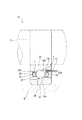
図1は、本発明の一実施の形態(第1実施形態)に係る転がり軸受1の軸平行断面図であり、図2は、図1に示される転がり軸受1のA−A矢視側面図である。
図1に示される転がり軸受1はアンギュラ玉軸受であり、内輪2と、外輪3と、この内輪2と外輪3との間に配設される複数の転動体4と、この複数の転動体4を周方向所定間隔に保持する複数のポケット5を有する環状体からなる保持器6とを備えており、内輪2と外輪3との間の環状空間における外輪3の内周面に給油ユニット10が固設されている。そして、回転輪である内輪2の内周面には軸Sが固定され、固定輪である外輪3の外周面はハウジングHに固定されている。
Hereinafter, embodiments of a rolling bearing according to the present invention will be described in detail with reference to the accompanying drawings.
FIG. 1 is an axial parallel cross-sectional view of a rolling bearing 1 according to an embodiment (first embodiment) of the present invention, and FIG. 2 is a side view of the rolling bearing 1 shown in FIG. It is.
A rolling bearing 1 shown in FIG. 1 is an angular ball bearing, and includes an
内輪2は、内輪本体部2aと、この内輪本体部2aの一端から軸方向に延出させた内輪延長部2cとを有しており、内輪本体部2aの外周には内輪軌道面2bが形成されている。
一方、外輪3は、外輪本体部3aと、この外輪本体部3aの一端から軸方向に延出させた外輪延長部3cとを有しており、外輪本体部2aの内周には外輪軌道面3bが形成されている。
内輪軌道面2bと外輪軌道面3bとの間に転動体4が転動自在に配設されている。
内輪延長部2cと外輪延長部3cは、軸方向において互いに対向する位置に配置されており、両延長部2c,3cの間の環状空間に給油ユニットが配設されている。
The
On the other hand, the
A
The
保持器6の軸方向両方側における内周面には、軸方向両端からポケット5の周縁の少なくとも一部に亘って、縮径することなくかつ全体として拡径する拡径部分20が形成されており、この拡径部分20の表面20aに撥油処理が施されている。具体的には、保持器6は、フェノール樹脂、ポリアミド樹脂、ポリフェニレンサルファイド樹脂などの親油性(潤滑油に対する親油性)の材料で作製されており、その表面は親油性を有しているが、本実施の形態では、拡径部分20の表面20aにイソシアネート基等の官能基を複数有するパーフルオロアルキルエーテルを重合させたフッ素系硬化膜、ポリテトラフルオロエチレンなどのフッ素系樹脂やシリコン系撥油材などの撥油性材料をコーティングすることによって、撥油性被膜7を形成している。また、隣接するポケット5間の柱部6aの内周面にも撥油性被膜7が形成されている。したがって、保持器6は、内周面が撥油性を有しており、それ以外の表面、例えば外周面やポケット内周面は親油性を有している。
The inner peripheral surface of both sides of the
なお、本明細書において、「縮径することなくかつ全体として拡径する」とは、始点から終点に至るまで連続して拡径している場合だけでなく、部分的に同径部が含まれている場合も含む趣旨である。始点と終点とを比較したとき、終点の方が拡径していることが、十分条件であるが、この条件を満たす場合であっても途中で部分的に縮径する場合は、「縮径することなくかつ全体として拡径する」には該当しない。拡径は、直線状に拡径させてもよいし、曲線状に拡径させてもよい。また、直線部分と曲線部分を含む形状であってもよい。 In the present specification, “expanding the diameter as a whole without reducing the diameter” not only includes the case where the diameter is continuously expanded from the start point to the end point, but also partially includes the same diameter portion. This is intended to include cases where When the start point and the end point are compared, it is a sufficient condition that the end point has a larger diameter. It does not correspond to “expanding the diameter as a whole without.” The diameter expansion may be linearly expanded or may be expanded in a curved line. Moreover, the shape containing a linear part and a curve part may be sufficient.
給油ユニット10は、図1〜2に示されるように、潤滑油を貯留するタンク11と、このタンク11内の潤滑油を吸引し吐出するポンプ12と、このポンプ12の吐出口に取り付けられたノズル13と、タンク11とポンプ12を連通するための配管14と、ポンプ12を駆動するための駆動部(図示省略)とを備えている。
ノズル13は、ポンプ12から軸方向に延ばされ、保持器6と、この保持器6と対向する内輪2の外周面との間の空間に挿入されている。また、ノズル13は、その先端付近において、転がり軸受1の回転方向側に曲げられた角部(図示省略)を有しており、この角部の先端に先端開口部13aが形成されている。
給油ユニット10では、ポンプ12によって、タンク11の潤滑油が吸引され、さらに、吸引された潤滑油がノズル13の先端開口部13aから吐出され、保持器6の内周面に潤滑油が滴下される。
As shown in FIGS. 1 and 2, the
The
In the
本実施の形態では、拡径部分20の表面20a及び柱部6aの内周面、つまり、保持器6の内周面全体に撥油性被膜7が形成されており、この撥油性被膜7上では、潤滑油の接触角が大きくなるため、潤滑油の流動性が高くなる。
したがって、ノズル13の先端開口部13aより保持器6の拡径部分20の表面20aに潤滑油を滴下すれば、転がり軸受1の回転による遠心力によって、滴下された潤滑油の油滴を即座に転動体4側に移動させ、ポケット5内に流動させることができる。このとき、柱部6aの内周面に移動した潤滑油は、転がり軸受1の回転によって周方向に移動してポケット5内に流動する。
In the present embodiment, the oil repellent coating 7 is formed on the
Therefore, if the lubricating oil is dripped onto the
そして、ポケット5内に流動した潤滑油は、転動体4の表面に付着し、この転動体4の自転及公転によって、ポケット内周面、内輪軌道面2b、外輪軌道面3b、保持器6外周面などに供給される。この保持器6外周面やポケット内周面は親油性を有しているので、濡れ性がよく、供給された潤滑油を保持し易い状態になっている。したがって、良好な潤滑作用を維持することができる。
なお、潤滑油の一部が保持器6の軸方向中心を越えて保持器6の他方側に移動することがあるが、本実施の形態では、この他方側にも拡径部分が形成されているので、転がり軸受1の回転による遠心力によって、潤滑油が転動体4側に戻されるため、保持器6の端部から潤滑油が流出することはない。
The lubricating oil that has flowed into the
In addition, a part of the lubricating oil may move to the other side of the
このように、保持器6の拡径部分20の表面20aに滴下した潤滑油は、潤滑を必要とする内輪軌道面や外輪軌道面などの部位に確実に効率よく供給されるので、潤滑油の無駄をなくして当該潤滑油の供給量を最小限にすることができる。また、必要量の潤滑油を確実に摺動ないしは転動部位に供給できるので、転がり軸受の焼付きを防止することができる。そして、供給する潤滑油の量を最小限にすることができることから、潤滑油を貯留するタンクに潤滑油を補充するインターバルが長くなり、転がり軸受のメンテナンスの負担が軽くなる。なお、タンクに潤滑油を補充することができないタイプの給油ユニットを備えた転がり軸受にあっては、当該転がり軸受の寿命を長くすることができる。
In this way, the lubricating oil dripped onto the
図3は、本発明の他の実施の形態(第2実施形態)に係る転がり軸受31の軸平行断面図である。
図3に示される転がり軸受31は、アンギュラ玉軸受であり、内輪32と、外輪33と、この内輪32と外輪33との間に配設される複数の転動体34と、この複数の転動体34を周方向所定間隔に保持する複数のポケット35を有する環状体からなる保持器36とを備えており、図示しない給油ユニットが転がり軸受31の外部に隣接配置されている。
FIG. 3 is an axial parallel cross-sectional view of a rolling bearing 31 according to another embodiment (second embodiment) of the present invention.
A rolling bearing 31 shown in FIG. 3 is an angular ball bearing, and includes an
内輪32の外周には内輪軌道面32aが形成されており、外輪33の内周には外輪軌道面33aが形成されており、両軌道面32a,33a間に転動体34が転動自在に配設されている。
An inner
本実施の形態では、図示しない給油ユニットが、ハウジングH等の固定部材の適宜の位置に取り付けられ、給油ユニットに含まれるポンプに取り付けられたノズル13が、保持器36と、この保持器36と対向する内輪32の外周面との間の空間に挿入されている。保持器36とノズル13の相対位置、保持器36の形状、材料、撥油性材料の種類、撥油性被膜の形成箇所、および、保持器36と、この保持器36と対向する内輪32の外周面との間の空間におけるノズル13の位置、ノズル13の形状、など、図1に示される実施の形態と同様になっている。そして、図1に示される実施の形態と同様にして、転がり軸受31への潤滑油の供給を行うことができる。
この実施の形態では、転がり軸受31の大きさ及び設置場所の環境等に関係なく給油ユニットを設定することができるので、例えば、給油ユニットのタンクを大きくすることによって、潤滑油を補充するインターバルを長くすることができ、転がり軸受31のメンテナンスの負担を軽減することができる。
In the present embodiment, an oil supply unit (not shown) is attached to an appropriate position of a fixing member such as the housing H, and a
In this embodiment, since the oil supply unit can be set regardless of the size of the rolling bearing 31 and the environment of the installation location, for example, by increasing the tank of the oil supply unit, the interval for replenishing the lubricating oil is increased. It can be lengthened and the maintenance burden of the rolling bearing 31 can be reduced.
なお、本発明は、前述した実施の形態に限定されるものではなく、種々の変更を加えることができる。例えば、前述した実施の形態では、保持器6の内周面に、その軸方向両端からそれぞれポケット5の周縁に亘り拡径部分が形成され、且つ、当該拡径部分の表面に撥油性被膜7が形成される構成としたが、図4に示される転がり軸受41のように、潤滑油の供給されない他方側の保持器46の内周面において、軸方向一端からポケット45の周縁に亘り拡径部分及び撥油性被膜7が形成されていない構成としても良い。
In addition, this invention is not limited to embodiment mentioned above, A various change can be added. For example, in the above-described embodiment, the diameter-enlarged portion is formed on the inner peripheral surface of the
1 転がり軸受
2 内輪
2b 内輪軌道面
2c 内輪延長部
3 外輪
3b 外輪軌道面
3c 外輪延長部
4 転動体
5 ポケット
6 保持器
7 撥油性被膜
10 給油ユニット
11 タンク
12 ポンプ
13 ノズル
20 拡径部分
31 転がり軸受
41 転がり軸受
DESCRIPTION OF SYMBOLS 1
Claims (3)
内周に外輪軌道面を有する外輪と、
前記内輪軌道面と前記外輪軌道面との間に配設される複数の転動体と、
前記複数の転動体を周方向所定間隔に保持するポケットを有する環状体からなる保持器とを備え、
軸方向一方側の前記内輪の外周面と前記保持器の内周面との間を通って潤滑油が供給される転がり軸受であって、
少なくとも軸方向一方側における前記保持器の内周面に、軸方向一端から前記ポケットの周縁に亘り、縮径することなくかつ全体として拡径する拡径部分が形成されており、且つ、当該拡径部分の表面が撥油性を有している
ことを特徴とする転がり軸受。 An inner ring having an inner ring raceway surface on the outer periphery;
An outer ring having an outer ring raceway surface on the inner periphery;
A plurality of rolling elements disposed between the inner ring raceway surface and the outer ring raceway surface;
A cage made of an annular body having pockets for holding the plurality of rolling elements at predetermined intervals in the circumferential direction;
A rolling bearing in which lubricating oil is supplied between the outer peripheral surface of the inner ring on one side in the axial direction and the inner peripheral surface of the cage,
At least on the inner peripheral surface of the cage on one side in the axial direction, a diameter-expanding portion is formed that extends from one end in the axial direction to the periphery of the pocket without expanding the diameter and as a whole. A rolling bearing characterized in that the surface of the diameter portion has oil repellency.
内周に外輪軌道面を有する外輪と、
前記内輪軌道面と前記外輪軌道面との間に配設される複数の転動体と、
前記複数の転動体を周方向所定間隔に保持するポケットを有する環状体からなる保持器とを備え、
少なくとも軸方向一方側の前記内輪の外周面と前記保持器の内周面との間を通って潤滑油が供給される転がり軸受であって、
軸方向両方側における前記保持器の内周面に、軸方向両端からそれぞれ前記ポケットの周縁に亘り、縮径することなくかつ全体として拡径する拡径部分が形成されており、且つ、当該拡径部分の表面が撥油性を有している
ことを特徴とする転がり軸受。 An inner ring having an inner ring raceway surface on the outer periphery;
An outer ring having an outer ring raceway surface on the inner periphery;
A plurality of rolling elements disposed between the inner ring raceway surface and the outer ring raceway surface;
A cage made of an annular body having pockets for holding the plurality of rolling elements at predetermined intervals in the circumferential direction;
A rolling bearing to which lubricating oil is supplied at least between the outer peripheral surface of the inner ring on one side in the axial direction and the inner peripheral surface of the cage,
On the inner peripheral surface of the cage on both sides in the axial direction, a diameter-expanded portion is formed that extends from the both ends in the axial direction to the periphery of the pocket without expanding the diameter as a whole. A rolling bearing characterized in that the surface of the diameter portion has oil repellency.
Priority Applications (1)
| Application Number | Priority Date | Filing Date | Title |
|---|---|---|---|
| JP2008022523A JP2009180367A (en) | 2008-02-01 | 2008-02-01 | Rolling bearing |
Applications Claiming Priority (1)
| Application Number | Priority Date | Filing Date | Title |
|---|---|---|---|
| JP2008022523A JP2009180367A (en) | 2008-02-01 | 2008-02-01 | Rolling bearing |
Publications (1)
| Publication Number | Publication Date |
|---|---|
| JP2009180367A true JP2009180367A (en) | 2009-08-13 |
Family
ID=41034499
Family Applications (1)
| Application Number | Title | Priority Date | Filing Date |
|---|---|---|---|
| JP2008022523A Pending JP2009180367A (en) | 2008-02-01 | 2008-02-01 | Rolling bearing |
Country Status (1)
| Country | Link |
|---|---|
| JP (1) | JP2009180367A (en) |
Cited By (4)
| Publication number | Priority date | Publication date | Assignee | Title |
|---|---|---|---|---|
| DE102011088232A1 (en) * | 2011-12-12 | 2013-06-13 | Aktiebolaget Skf | Bearing cage and bearing cage segment |
| CN107366681A (en) * | 2016-05-11 | 2017-11-21 | 株式会社捷太格特 | Rolling bearing system |
| EP3276194A4 (en) * | 2015-03-24 | 2019-01-16 | NTN Corporation | Bearing device |
| EP3276195A4 (en) * | 2015-03-23 | 2019-01-23 | NTN Corporation | Bearing device and machinery |
-
2008
- 2008-02-01 JP JP2008022523A patent/JP2009180367A/en active Pending
Cited By (6)
| Publication number | Priority date | Publication date | Assignee | Title |
|---|---|---|---|---|
| DE102011088232A1 (en) * | 2011-12-12 | 2013-06-13 | Aktiebolaget Skf | Bearing cage and bearing cage segment |
| EP2604877A1 (en) * | 2011-12-12 | 2013-06-19 | Aktiebolaget SKF | Bearing cage and bearing cage segment |
| US8783959B2 (en) | 2011-12-12 | 2014-07-22 | Aktiebolaget Skf | Bearing cage having lipophobic or oleophobic surface(s) |
| EP3276195A4 (en) * | 2015-03-23 | 2019-01-23 | NTN Corporation | Bearing device and machinery |
| EP3276194A4 (en) * | 2015-03-24 | 2019-01-16 | NTN Corporation | Bearing device |
| CN107366681A (en) * | 2016-05-11 | 2017-11-21 | 株式会社捷太格特 | Rolling bearing system |
Similar Documents
| Publication | Publication Date | Title |
|---|---|---|
| EP1811190B1 (en) | Rolling bearing device and spindle | |
| JP2007092886A (en) | Rolling bearing device | |
| JP2016023757A (en) | Rolling bearing device and oil supply unit | |
| JP2009180367A (en) | Rolling bearing | |
| JP2007303558A (en) | Rolling bearing device | |
| US9958005B2 (en) | Oil-lubricated bearing device and vacuum pump | |
| EP2463536A1 (en) | Bearing Assembly | |
| JP7307102B2 (en) | sliding parts | |
| CN107559312B (en) | Tapered roller bearing | |
| CN107429745B (en) | Tapered roller bearing | |
| JP2009209952A (en) | Tapered roller bearing | |
| JP2009144745A (en) | Rolling bearing device | |
| JP2016029303A (en) | Rolling bearing | |
| JP2017075695A (en) | Oil lubrication bearing device and vacuum pump | |
| JP2006194406A (en) | Rolling bearing device | |
| JP2008223891A (en) | Tapered roller bearing | |
| JP2011153564A (en) | Tappet for pump | |
| JP2004332928A (en) | Bearing device and spindle device | |
| JP5045409B2 (en) | Rolling bearing | |
| JP2009047265A (en) | Rolling bearing device | |
| JP6606201B2 (en) | Ball bearing cage and ball bearing | |
| JP2005337349A (en) | Bearing device and main spindle device using it | |
| JP2009275759A (en) | Deep groove ball bearing | |
| JP2012172775A (en) | Sealed bearing device | |
| JP2017036761A (en) | Bearing device and rotary machine |
Legal Events
| Date | Code | Title | Description |
|---|---|---|---|
| A621 | Written request for application examination |
Free format text: JAPANESE INTERMEDIATE CODE: A621 Effective date: 20110120 |
|
| A072 | Dismissal of procedure |
Free format text: JAPANESE INTERMEDIATE CODE: A073 Effective date: 20120529 |