JP2009168024A - Two aerofoil type blade including spacer strip - Google Patents
Two aerofoil type blade including spacer strip Download PDFInfo
- Publication number
- JP2009168024A JP2009168024A JP2009003165A JP2009003165A JP2009168024A JP 2009168024 A JP2009168024 A JP 2009168024A JP 2009003165 A JP2009003165 A JP 2009003165A JP 2009003165 A JP2009003165 A JP 2009003165A JP 2009168024 A JP2009168024 A JP 2009168024A
- Authority
- JP
- Japan
- Prior art keywords
- blade
- wing
- strip
- trailing edge
- leading edge
- Prior art date
- Legal status (The legal status is an assumption and is not a legal conclusion. Google has not performed a legal analysis and makes no representation as to the accuracy of the status listed.)
- Granted
Links
- 125000006850 spacer group Chemical group 0.000 title claims abstract description 7
- 230000007423 decrease Effects 0.000 claims description 5
- 239000000835 fiber Substances 0.000 description 3
- PXHVJJICTQNCMI-UHFFFAOYSA-N Nickel Chemical compound [Ni] PXHVJJICTQNCMI-UHFFFAOYSA-N 0.000 description 2
- 239000000463 material Substances 0.000 description 2
- 239000011159 matrix material Substances 0.000 description 2
- 229910052751 metal Inorganic materials 0.000 description 2
- 239000002184 metal Substances 0.000 description 2
- 229910000838 Al alloy Inorganic materials 0.000 description 1
- 229920000049 Carbon (fiber) Polymers 0.000 description 1
- 229920000271 Kevlar® Polymers 0.000 description 1
- 229910000831 Steel Inorganic materials 0.000 description 1
- 229910001069 Ti alloy Inorganic materials 0.000 description 1
- 239000004917 carbon fiber Substances 0.000 description 1
- 239000000919 ceramic Substances 0.000 description 1
- 229910017052 cobalt Inorganic materials 0.000 description 1
- 239000010941 cobalt Substances 0.000 description 1
- GUTLYIVDDKVIGB-UHFFFAOYSA-N cobalt atom Chemical compound [Co] GUTLYIVDDKVIGB-UHFFFAOYSA-N 0.000 description 1
- 239000002131 composite material Substances 0.000 description 1
- 239000000446 fuel Substances 0.000 description 1
- 239000003365 glass fiber Substances 0.000 description 1
- 239000004761 kevlar Substances 0.000 description 1
- VNWKTOKETHGBQD-UHFFFAOYSA-N methane Chemical compound C VNWKTOKETHGBQD-UHFFFAOYSA-N 0.000 description 1
- 229910052759 nickel Inorganic materials 0.000 description 1
- 229920000642 polymer Polymers 0.000 description 1
- 239000010959 steel Substances 0.000 description 1
- 239000003351 stiffener Substances 0.000 description 1
- 229910000601 superalloy Inorganic materials 0.000 description 1
Images
Classifications
-
- F—MECHANICAL ENGINEERING; LIGHTING; HEATING; WEAPONS; BLASTING
- F01—MACHINES OR ENGINES IN GENERAL; ENGINE PLANTS IN GENERAL; STEAM ENGINES
- F01D—NON-POSITIVE DISPLACEMENT MACHINES OR ENGINES, e.g. STEAM TURBINES
- F01D9/00—Stators
- F01D9/02—Nozzles; Nozzle boxes; Stator blades; Guide conduits, e.g. individual nozzles
- F01D9/04—Nozzles; Nozzle boxes; Stator blades; Guide conduits, e.g. individual nozzles forming ring or sector
- F01D9/041—Nozzles; Nozzle boxes; Stator blades; Guide conduits, e.g. individual nozzles forming ring or sector using blades
-
- F—MECHANICAL ENGINEERING; LIGHTING; HEATING; WEAPONS; BLASTING
- F01—MACHINES OR ENGINES IN GENERAL; ENGINE PLANTS IN GENERAL; STEAM ENGINES
- F01D—NON-POSITIVE DISPLACEMENT MACHINES OR ENGINES, e.g. STEAM TURBINES
- F01D5/00—Blades; Blade-carrying members; Heating, heat-insulating, cooling or antivibration means on the blades or the members
- F01D5/12—Blades
- F01D5/14—Form or construction
- F01D5/141—Shape, i.e. outer, aerodynamic form
- F01D5/146—Shape, i.e. outer, aerodynamic form of blades with tandem configuration, split blades or slotted blades
-
- F—MECHANICAL ENGINEERING; LIGHTING; HEATING; WEAPONS; BLASTING
- F04—POSITIVE - DISPLACEMENT MACHINES FOR LIQUIDS; PUMPS FOR LIQUIDS OR ELASTIC FLUIDS
- F04D—NON-POSITIVE-DISPLACEMENT PUMPS
- F04D29/00—Details, component parts, or accessories
- F04D29/66—Combating cavitation, whirls, noise, vibration or the like; Balancing
- F04D29/68—Combating cavitation, whirls, noise, vibration or the like; Balancing by influencing boundary layers
- F04D29/681—Combating cavitation, whirls, noise, vibration or the like; Balancing by influencing boundary layers especially adapted for elastic fluid pumps
-
- F—MECHANICAL ENGINEERING; LIGHTING; HEATING; WEAPONS; BLASTING
- F05—INDEXING SCHEMES RELATING TO ENGINES OR PUMPS IN VARIOUS SUBCLASSES OF CLASSES F01-F04
- F05B—INDEXING SCHEME RELATING TO WIND, SPRING, WEIGHT, INERTIA OR LIKE MOTORS, TO MACHINES OR ENGINES FOR LIQUIDS COVERED BY SUBCLASSES F03B, F03D AND F03G
- F05B2240/00—Components
- F05B2240/20—Rotors
- F05B2240/33—Shrouds which are part of or which are rotating with the rotor
-
- F—MECHANICAL ENGINEERING; LIGHTING; HEATING; WEAPONS; BLASTING
- F05—INDEXING SCHEMES RELATING TO ENGINES OR PUMPS IN VARIOUS SUBCLASSES OF CLASSES F01-F04
- F05D—INDEXING SCHEME FOR ASPECTS RELATING TO NON-POSITIVE-DISPLACEMENT MACHINES OR ENGINES, GAS-TURBINES OR JET-PROPULSION PLANTS
- F05D2240/00—Components
- F05D2240/10—Stators
- F05D2240/12—Fluid guiding means, e.g. vanes
- F05D2240/126—Baffles or ribs
Abstract
Description
本発明は、前縁及び後縁を有するブレードに関する。 The present invention relates to a blade having a leading edge and a trailing edge.
以下の記述において、用語「前縁」及び「後縁」は、ブレードに沿った空気の通常の流れ方向に関連して定義される。 In the following description, the terms “leading edge” and “trailing edge” are defined in relation to the normal flow direction of air along the blade.
ターボ機械において、空気は、ターボ機械の主軸Pに沿って軸方向に配設された複数のブレード段によって圧縮され、各段は、上記主軸Pまわりの外周周囲に配設された一連のブレードを備える。そのような段は、ブレード付きホイールとして知られている。主軸Pが中心とされた外周プラットフォームから、ブレードは、環状ケーシングに向かって略半径方向に外側に延在している。ブレードの高さは、ブレードの半径の寸法、すなわち、実質的にケーシングの半径とプラットフォームの半径との差異である。 In a turbo machine, air is compressed by a plurality of blade stages arranged in the axial direction along the main axis P of the turbo machine, and each stage has a series of blades arranged around the outer periphery around the main axis P. Prepare. Such a step is known as a bladed wheel. From the outer circumferential platform centered on the main axis P, the blades extend outward in a substantially radial direction toward the annular casing. The height of the blade is the dimension of the blade radius, ie substantially the difference between the casing radius and the platform radius.
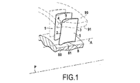
ブレード付きホイールの一部を示している図1において示されるように、ブレード付きホイールの各ブレード1は、プラットフォーム80の半径方向外側表面(壁)81とケーシング90の半径方向内側表面(壁)91との間に延在している。ブレード1が1枚の翼によって構成されていることから、それは、1枚翼型ブレードと称される。ブレード1の半径方向内側端部8は、プラットフォーム80に固定されている。ブレード1の半径方向外側端部9は、固定翼を構成する場合にはケーシング90に固定されており、そうでなければロータブレードを構成する場合には自由端である。このように、ブレード付きホイールは、プラットフォーム80の上記壁81とケーシング90の上記壁91との間に位置しているブレード1を有し、ブレードは、固定翼1又はロータブレード1であり得る。
As shown in FIG. 1, which shows a portion of a bladed wheel, each blade 1 of the bladed wheel has a radially outer surface (wall) 81 of the
各ブレード1は、前縁2及び後縁3を有し、これらの2つの縁を相互に接続する軸A(ブレードの軸)は、ターボ機械の主軸Pに略平行である。前縁2と後縁3とを相互に接続する面の一方が凸状(凸面4)であり、且つ、前縁と後縁とを相互に接続する他方の面が凹状(凹面5)であるように、各ブレード1は、軸Aに対して湾曲されている。 Each blade 1 has a leading edge 2 and a trailing edge 3, and an axis A (blade axis) connecting these two edges to each other is substantially parallel to the main axis P of the turbomachine. One of the surfaces connecting the leading edge 2 and the trailing edge 3 is convex (convex surface 4), and the other surface connecting the leading edge and the trailing edge is concave (concave surface 5). Thus, each blade 1 is curved with respect to the axis A.
ブレード付きホイール上のブレードの枚数は、ブレード付きホイールについての軽量性を得ることと、(高速で回転するブレード付きホイールに起因する熱応力及び機械的応力を受けるときの)ブレードについての高い機械的強度を得ることと、ブレードの空気力学的効率を最大化することと、その結果としてブレード付きホイールの空気力学的効率を最大化することとの間の妥協として決定されている。現在のところ、ブレードの幾何形状は、そのようなブレードを支持するブレード付きホイールの空気力学的性能において、いかなる著しい改善の達成も可能としない。 The number of blades on the bladed wheel provides light weight for the bladed wheel and high mechanical strength for the blade (when subjected to thermal and mechanical stress due to the bladed wheel rotating at high speed) It has been determined as a compromise between gaining strength and maximizing the aerodynamic efficiency of the blade and consequently maximizing the aerodynamic efficiency of the bladed wheel. At present, the blade geometry does not allow any significant improvement in the aerodynamic performance of the bladed wheel that supports such blades.
本発明は、ブレードの機械的強度の妥協なしで、より良好な空気力学的効率を提供するブレードを提供することを目的とする。 The present invention seeks to provide a blade that provides better aerodynamic efficiency without compromising the mechanical strength of the blade.
この目的は、ブレードが、ブレードの前縁と後縁との間に延在している内面及び外面を有する第1の翼と、ブレードの前縁と後縁との間に延在している内面及び外面を有する第2の翼と、第1の翼の内面と第2の翼の内面とを相互に接続する少なくとも1つのスペーサストリップとを備え、第1の翼の上記内面が略全領域にわたって第2の翼の上記内面に面するように、第1の翼及び第2の翼が隣り合って配列されており、少なくとも1つのストリップが後縁まで延在している、ということによって達成される。 The purpose is that the blade extends between a first wing having an inner surface and an outer surface extending between the leading and trailing edges of the blade and the leading and trailing edges of the blade. A second wing having an inner surface and an outer surface, and at least one spacer strip interconnecting the inner surface of the first wing and the inner surface of the second wing, wherein the inner surface of the first wing is substantially the entire area. Achieved by the first wing and the second wing being arranged next to each other so as to face the inner surface of the second wing, with at least one strip extending to the trailing edge. Is done.
これらの配置を用いて、本発明のブレードは、1枚の翼によって構成されたブレードよりも高い機械的強度を有する。この増加された機械的強度は、ブレードを構成する各翼の平均厚みが低減されるのを可能とする。この厚みの低減は、翼の周囲を通過する空気の自然な流れが阻害されにくくなることから、ブレードの空気力学的効率の改善をもたらす。さらに、特にストリップがブレードの後縁の範囲まで延在していることから、ストリップは2枚の翼間の空気を案内し、案内された空気自体が、ブレードの後縁において2枚の翼の外壁に沿って流れる空気を案内するのに寄与する。これは、後縁における流れの乱れを最小化する。したがって、ブレードの空気力学的効率は、さらに改善される。 With these arrangements, the blade of the present invention has a higher mechanical strength than a blade constituted by a single blade. This increased mechanical strength allows the average thickness of each wing constituting the blade to be reduced. This reduction in thickness results in improved aerodynamic efficiency of the blade because the natural flow of air passing around the wing is less likely to be hindered. Furthermore, the strip guides the air between the two wings, in particular because the strip extends to the extent of the trailing edge of the blade, and the guided air itself is at the trailing edge of the blade. Contributes to guiding the air flowing along the outer wall. This minimizes flow turbulence at the trailing edge. Thus, the aerodynamic efficiency of the blade is further improved.
有利には、ブレードは、最低3つのストリップを有する。 Advantageously, the blade has a minimum of three strips.
このより多いストリップ数は、ブレードをより強固にするとともに、第1の翼と第2の翼との間の空間における空気流に対するより良好な案内をもたらすのに役立つ。 This higher number of strips helps to make the blade stronger and provide better guidance for air flow in the space between the first and second wings.
本発明はまた、一連の本発明のブレードをその外周周囲に含むブレード付きホイールを提供する。 The present invention also provides a bladed wheel comprising a series of inventive blades around its periphery.
本発明のブレードの幾何形状によって可能とされるような(1枚翼型ブレードと比較された)本発明の各ブレードの空気力学的効率の改善は、従来のブレード付きホイール上の1枚翼型ブレード間の間隔と比較して、ブレード付きホイールのプラットフォームの外周周囲にブレードがより広い間隔をあけて配置されるのを可能とする。概して、本発明の個々のブレードが1枚翼型ブレードよりも重い可能性があるという事実にもかかわらず、本発明のブレード付きホイールは、それでもなお、1枚翼型ブレードが取り付けられたブレード付きホイールの重量以下の重量を有することができ、より高い効率をもたらすことができる。 The improvement in aerodynamic efficiency of each blade of the present invention (compared to a single blade blade), as enabled by the blade geometry of the present invention, is a single blade type on a conventional bladed wheel. Compared to the spacing between the blades, it allows the blades to be arranged more widely around the circumference of the platform of the bladed wheel. In general, despite the fact that individual blades of the present invention may be heavier than single blade blades, the bladed wheel of the present invention still has a blade with a single blade mounted. It can have a weight that is less than or equal to the weight of the wheel, resulting in higher efficiency.
非限定的な例によって与えられた以下の実施形態の詳細な記述を読むことにより、本発明は、十分に理解されることができ、その利点は、よりよく現れる。記述は、添付図面を参照する。 By reading the following detailed description of embodiments given by way of non-limiting examples, the present invention can be fully understood, and the advantages will appear better. The description refers to the accompanying drawings.
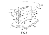
図2は、プラットフォーム80上に取り付けられた本発明のブレード100を示している。ブレード100は、第1の翼10と、第2の翼20とを備える。これら翼のそれぞれは、1枚翼型ブレードと同様であり、したがって、凸面と、凹面と、前縁と、後縁とを有する。これら2枚の翼は、第1の翼10の凹面15が略全領域にわたって第2の翼20の凸面24に面するように、隣り合って配列されている。その結果、第1のブレード10と第2のブレード20との間に空間40が画定されている。したがって、凹面15は、第1の翼10の内面15と称され、凸面24は、第2の翼20の内面24と称される。第1の翼10の凸面14及び第2の翼20の凹面25は、ブレード100の外面を構成する。したがって、凸面14は、第1の翼10の外面14と称され、凹面25は、第2の翼20の外面25と称される。したがって、ブレード100は、2枚翼型ブレードと称される。
FIG. 2 shows the
第1の翼10の内面15及び第2の翼20の内面24は、空間40内に配設された1つより多いスペーサストリップ30によって相互に接続されている。各ストリップは、前縁22と、後縁23と、それらの間に半径方向内面38(すなわち、プラットフォーム80の方を向いている)及び半径方向外面39(すなわち、ケーシング90の方を向いている)を有する中央部分とを有する。
The
各ストリップ30は、2つの内面を相互に接続する連続的な接続要素であり、接続要素は、ブレード100の機械的強度及び凝集性に寄与する補強材と、第1の翼10と第2の翼20との間の空気流を案内する半径方向内面38及び半径方向外面39に沿ったガイドとの双方を形成している。各ストリップ30の内部は、中空であっても中空でなくてもよい。
Each
ストリップ30は、実質的に、第1の翼10の前縁12及び第2の翼20の前縁22から第1の翼10の後縁13及び第2の翼20の前縁23まで延在している。したがって、ブレード100の前縁102は、第1の翼10の前縁12及び第2の翼20の前縁22によって構成される。ブレード100の後縁103は、第1の翼10の後縁13及び第2の翼20の後縁23によって構成される。前縁102から後縁103に向かう方向に沿って、ストリップ30は、前縁102及び後縁103に対して略垂直に向けられている。
The
ブレード100は、2枚の翼を備えることから、1枚翼型ブレードよりも高い機械的強度を有する。この増加された強度は、ブレード100を構成する各翼の平均厚みが低減されるのを可能とする。すなわち、第1及び第2の翼10、20は、それぞれ、1枚翼型ブレードが作り出すものよりも薄い厚みを有する。ブレード100の総重量は、1枚翼型ブレード1の重量と略等しい可能性がありさえもする。さらに、上述したように、ブレード100は、ストリップ30のために、1枚翼型ブレードよりも良好な空気力学的効率を有する。本発明のブレード100を有するブレード付きホイールにおいて、この空気力学的効率の改善は、従来のブレード付きホイールにおける1枚翼型ブレード間の間隔と比較して、ブレード付きホイールのプラットフォーム80の外周周囲にブレード100が互いにさらに広い間隔をあけて配置されるのを可能とする。要約すれば、本発明のブレード付きホイールは、したがって、1枚翼型ブレードが取り付けられたブレード付きホイールの重量以下の重量のものとすることができる。これは、本発明のブレード付きホイールが取り付けられたターボ機械の重量の低減をもたらし、その結果、その燃費の低減をもたらす。
Since the
さらに、本発明のブレード100は、ブレード100が1枚翼型ブレードよりも大きな熱交換面積を有することから、1枚翼型ブレードよりも高温に耐える高い能力を有する。
Furthermore, the
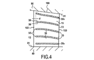
ブレード100は、複数のストリップ30を有してもよい。例えば、ブレードは、ブレード100の高さの0%から30%の範囲に位置している第1のストリップ30Aと、ブレード100の高さの70%から100%の範囲に位置している最後のストリップ30Nと、ブレード100の高さの実質的に中間に位置しているストリップとである最低3つのストリップを有してもよい。0%の高さは、ブレードの半径方向内側端部に一致しており、100%の高さは、ブレード100の半径方向外側端部に一致している。必要に応じて、さらなるストリップが上のストリップとの間に一定の間隔をあけて位置する。
The
プラットフォーム80の半径方向外側表面81によって流れに発生される乱れを低減することにおいてより効果的であるために、第1のストリップ30Aがプラットフォーム80から離れすぎない(具体的にはブレード100の高さの30%未満である)ことは重要である。同様に、ケーシング90の半径方向内側表面91によって流れに発生される乱れを低減することにおいてより効果的であるために、最後のストリップ30Nがケーシング90から離れすぎない(具体的にはブレード100の高さの少なくとも70%である)ことは重要である。
The radially
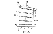
ブレード100は、3つよりも多い数、例えば、その全高にわたって分散配置された4つ、5つ、6つ、7つ、又は、それ以上のストリップを有してもよい。図2から図5は、5つのストリップ30を有するブレード100を示している。第1の翼10と第2の翼20との間を十分な空気流が通過するのを可能とするように、また、ブレード100の重量を最小化するように、それでもなお、ストリップ数は多すぎないのが好ましい。したがって、2つの隣接するストリップ30間の半径方向の距離は、第1の翼10の内面15と第2の翼20の内面24との間の距離Dよりも長いのが好ましい。
The
第1の翼10の内面15と第2の翼20の内面24との間の距離Dは、第1又は第2の翼の最大厚みの3倍以下である。例えば、距離Dは、上記最大厚みと同じ桁であり得る。
The distance D between the
第1の翼10と第2の翼20との間の距離Dは、15ミリメートル(mm)未満であるのが好ましい。例えば、距離Dは、2mmから5mmの範囲であり得る。この距離Dは、前縁32と後縁33との間においてストリップ30に沿って変化してもよく、その場合、距離Dは、2枚の翼間の平均距離である。
The distance D between the
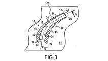
有利には、ブレード100を有するブレード付きホイールにおいて、ストリップ30は、それぞれ、上記ストリップ30に沿った空気流における乱れ/旋流が最小化されるような外形を有する。例えば、第1の翼10と第2の翼20との間の空間40における空気流に対する擾乱を最小化するように、ストリップ30が存在していない場合にこの空気流が後に続く流線に、ストリップ30は実質的に沿って延在している。
Advantageously, in a bladed wheel with
特に、第1のストリップ30A、すなわち、プラットフォーム80の壁(半径方向外側表面81)に最も近いストリップの外形及び配置、及び、最後のストリップ30N、すなわち、ケーシング90の壁(半径方向内側表面91)に最も近いストリップの外形及び配置は、特に重要である。
In particular, the
翼間の流線は、特に、ブレードの半径方向内側端部及び半径方向外側端部において、それぞれ、プラットフォーム80の壁81及びケーシング90の壁91によって定義される。すなわち、これらの壁に近い流線は、上記壁に略平行である。したがって、図4及び図5において示されるように、第1のストリップ30Aは、プラットフォーム80の壁81に略平行であり、最後のストリップ30Nは、ケーシング90の壁91に略平行である。
The streamlines between the blades are defined by the
例えば、ストリップ30の少なくとも1つは、直線状である。
For example, at least one of the
一例として、ストリップ30の少なくとも1つは、上記ブレードの高さ方向に延在する少なくとも1つの面(すなわち、ターボ機械の主軸Pを含む半径方向の面)において湾曲を有する。
As an example, at least one of the
ストリップ30が存在していない場合に生じ得るようにストリップ30が空間40における空気流に続かないことも可能であり、それどころか、これらのストリップが空気をブレード100の根元部に向かって強制的に流すのを可能とする。一般に、分岐が2枚のブレード間の空気流において生じる(すなわち、2枚の隣接するブレード間を通る空気流は、ブレードに沿って流れるのに従ってブレード根元部から先端に向かって上昇する傾向がある)ことが知られており、これは、望ましくないことが知られている。空間40における空気流をブレード100の根元部に向かって強制的に流すことにより、2枚の隣接するブレード100の間の空気流は、影響を及ぼされ、その結果、この空気流における分岐を低減するのに寄与する。
It is also possible that the
図2及び図4において、ストリップ30は、それぞれ、前縁32と後縁33との間において一定の厚み(ストリップ30の厚みは、それが属するブレード100の高さ方向における寸法である)を有するとして示されている。その結果、ストリップ30の前縁32及び後縁33は、略長方形である。あるいは、前縁32が鋭い縁を形成するように、ストリップ30の厚みは、その中央から前縁32に向かって減少していってもよい。さらに、代わりに、後縁33が鋭い縁を形成するように、ストリップ30の厚みは、その中央から後縁33に向かって減少していってもよい。結果として、第1の翼10と第2の翼20との間の空間40における空気流に対する擾乱は、一定の厚みのストリップによって発生される擾乱と比較して減少する。
2 and 4, the
図5において示されるように、ストリップ30の厚みの低減は、漸進的であってもよく、又は、厚みは、ストリップ30に沿って略一定であってもよく、端部(前縁32及び/又は後縁33)の近傍においてのみ減少してもよい。
As shown in FIG. 5, the reduction in the thickness of the
ブレード又は翼の内面/外面の外形は、上記面の表面形状として定義される。例えば、第1の翼の内面15及び第2の翼の内面24の外形は同一であり、第1の翼の外面14及び第2の翼の外面25の外形は同一である。それにもかかわらず、1枚翼型ブレードと比較した本発明のブレード100の異なる形状は、ブレード100の空気力学的特性に対する改良をもたらす。有利には、第1の翼10と第2の翼20との間の空間40及びブレード100の周囲における空気流が最適化されるように、第1の翼10の外面14、第1の翼10の内面15、第2の翼20の内面24、及び、第2の翼20の外面25は、全て、異なる外形を有する。さらに、第1の翼10の外面14の外形は、1枚翼型ブレードの凸面4の外形と異なり、第2の翼20の外面25の外形は、従来の1枚翼型ブレードの凹面5の外形と異なる。特に、第1の翼10の内面及び外面の外形並びに第2の翼20の内面及び外面の外形は、それぞれ、それらの間のいずれのストリップ30も接続することなく互いに近接して配置された種類の第1の翼の内面及び外面の外形並びに第2の翼の内面及び外面の外形と異なる。
The profile of the inner / outer surface of the blade or wing is defined as the surface shape of the surface. For example, the outer shapes of the
ストリップ30は、図5において示されるように、ブレード100の前縁102から後縁103まで延在している。あるいは、ストリップ30は、図4において示されるように、前縁102から一定の距離にあって後縁103の範囲まで延在してもよい。したがって、ストリップ30の前縁32は、ブレード100の前縁102から距離dだけ後退した位置において始まる。一例として、この距離dは、前縁102と後縁103との間の距離の10%未満である。
The
ストリップ30を含む平面又は表面は、ストリップ30によって連結された翼の内面15、24に対して略垂直である。あるいは、ストリップ30は、ストリップの前縁32を後縁33に連結する中央の曲面に関してねじられてもよい。そのようなねじれは、第1の翼10と第2の翼20との間の空間40における空気流に対する擾乱を最小化するように、ストリップ30が存在していない場合にこの空気流が後に続く流線にストリップ30が実質的に続くのを保証するのに役立つ。
The plane or surface containing the
ブレードは、鋼鉄、ニッケルもしくはコバルト系超合金、チタン合金、アルミニウム合金、又は、例えば、炭素繊維、ケブラー繊維、ガラス繊維、もしくは金属繊維等の繊維によって補強された、ポリマー、セラミック、もしくは金属母材等の母材を有する複合材料等、様々な材料から作られ得る。 The blade is a polymer, ceramic, or metal matrix reinforced with steel, nickel or cobalt-based superalloy, titanium alloy, aluminum alloy, or fibers such as carbon fiber, Kevlar fiber, glass fiber, or metal fiber It can be made from a variety of materials, such as a composite material having a matrix such as.
本発明のブレード100は、ブレード100を構成する材料に応じて、様々な方法を使用して作られ得る。
The
上の記述において、ブレード100は、2枚の翼を有する。代わりに、ブレード100は、2枚よりも多い翼を有することもあり得る。例えば、ブレード100はまた、第1の翼10と第2の翼20との間に位置する第3の翼を有することもできる。第3の翼は、ブレード100の前縁102と後縁103との間に延在している第1及び第2の面を有する。第1の面は、少なくとも1つのスペーサストリップ30によって第1の翼10の内面15に接続されており、第2の面はまた、少なくとも上記スペーサストリップ30によって第2の翼20の内面24に接続されている。
In the above description, the
したがって、ブレード100は、3枚の翼を有し、第3の翼は、第1の翼10と第2の翼20との間に位置している。これらの3枚の翼は、第1の翼10の凹面15が略全領域にわたって第3の翼の凸面(第1の面)に面し、且つ、第2の翼20の凸面24が略全領域にわたって第3の翼の凹面に面するように、隣り合って配列されている。第1の翼10を第2の翼20に接続するストリップ30は、第3の翼を貫通する(又は、ブレードが作られる方法に応じて、上記第3の翼と交差する箇所で上記第3の翼の一部となる)。各ストリップ30が、第1の翼10と第3の翼とを相互に接続する第1の部分と、この第1の部分と並んで第3の翼を第2の翼20に接続する第2の部分の、2つの部分から作られることが考慮されてもよい。
Therefore, the
この3枚翼型ブレード100は、翼間及び上記ブレードの外部に沿った空気流がより良好に案内されることから、2枚翼型ブレード100よりも空気力学的により効率的である。その結果、さらに間隔をあけてブレードを配置することにより、ブレード付きホイール上のブレード100の総数を低減するのを可能とし、その結果、1枚翼型ブレードから作られたブレード付きホイールよりも軽量化したブレード付きホイールが得られる。
The three-
本発明は、本発明の少なくとも1枚のブレード100を含むターボ機械に適用される。
The present invention applies to a turbomachine including at least one
本発明は、非冷低圧タービン用のロータブレード又は固定翼について上に記述されている。本発明はまた、非冷高圧タービン用のロータブレード又は固定翼にも適用される。 The present invention has been described above for rotor blades or stationary blades for non-cold low pressure turbines. The invention also applies to rotor blades or stationary blades for non-cold high pressure turbines.
10 第1の翼
12、22、32、102 前縁
13、23、33、103 後縁
14、24 凸面
15、25 凹面
20 第2の翼
30、30A、30N ストリップ
38 半径方向内面
39 半径方向外面
40 空間
80 プラットフォーム
81 半径方向外側表面
90 ケーシング
91 半径方向内側表面
100 ブレード
d、D 距離
10
Claims (14)
Applications Claiming Priority (2)
| Application Number | Priority Date | Filing Date | Title |
|---|---|---|---|
| FR0850120 | 2008-01-10 | ||
| FR0850120A FR2926322B1 (en) | 2008-01-10 | 2008-01-10 | DAWN BI-BLADE WITH BLADES. |
Publications (2)
| Publication Number | Publication Date |
|---|---|
| JP2009168024A true JP2009168024A (en) | 2009-07-30 |
| JP5474358B2 JP5474358B2 (en) | 2014-04-16 |
Family
ID=39832654
Family Applications (1)
| Application Number | Title | Priority Date | Filing Date |
|---|---|---|---|
| JP2009003165A Active JP5474358B2 (en) | 2008-01-10 | 2009-01-09 | Two-blade blade with spacer strip |
Country Status (6)
| Country | Link |
|---|---|
| US (1) | US8021113B2 (en) |
| EP (1) | EP2078824B1 (en) |
| JP (1) | JP5474358B2 (en) |
| CA (1) | CA2649397C (en) |
| FR (1) | FR2926322B1 (en) |
| RU (1) | RU2492330C2 (en) |
Cited By (1)
| Publication number | Priority date | Publication date | Assignee | Title |
|---|---|---|---|---|
| JP7390920B2 (en) | 2020-02-14 | 2023-12-04 | 三菱重工業株式会社 | Boosting equipment, carbon dioxide cycle plants and combined cycle plants |
Families Citing this family (6)
| Publication number | Priority date | Publication date | Assignee | Title |
|---|---|---|---|---|
| US10145253B2 (en) * | 2012-04-05 | 2018-12-04 | Safran Aircraft Engines | Stator vane formed by a set of vane parts |
| US9506353B2 (en) | 2012-12-19 | 2016-11-29 | United Technologies Corporation | Lightweight shrouded fan blade |
| US20180017037A1 (en) * | 2016-07-14 | 2018-01-18 | James L. Kissel | Hub and Rotor Assemby for Wind Turbines with Conjoined Turbine Blades |
| US20190101128A1 (en) * | 2017-10-01 | 2019-04-04 | Papa Abdoulaye MBODJ | Wing or blade design for wingtip device, rotor, propeller, turbine, and compressor blades with energy regeneration |
| FR3081913B1 (en) * | 2018-06-04 | 2021-01-08 | Safran Aircraft Engines | TURBOMACHINE VANE INCLUDING AN ANTI-SWIRL VANE |
| FR3087828B1 (en) * | 2018-10-26 | 2021-01-08 | Safran Helicopter Engines | MOBILE TURBOMACHINE BLADE |
Citations (3)
| Publication number | Priority date | Publication date | Assignee | Title |
|---|---|---|---|---|
| JPH05280495A (en) * | 1992-03-31 | 1993-10-26 | Ishikawajima Harima Heavy Ind Co Ltd | Fan moving blade |
| JPH08159090A (en) * | 1994-12-01 | 1996-06-18 | Sharp Corp | Axial flow fan |
| JP2001304193A (en) * | 2000-04-27 | 2001-10-31 | Sanki Technos Kk | Blower equipped with multi-guide vane |
Family Cites Families (25)
| Publication number | Priority date | Publication date | Assignee | Title |
|---|---|---|---|---|
| DE573799C (en) * | 1930-12-05 | 1933-04-05 | Johanna Langhans Geb Ulrich | Blading for gas and steam turbines |
| US2714499A (en) * | 1952-10-02 | 1955-08-02 | Gen Electric | Blading for turbomachines |
| US3040971A (en) * | 1960-03-02 | 1962-06-26 | American Mach & Foundry | Methods of compressing fluids with centripetal compressors |
| US3335483A (en) * | 1961-12-19 | 1967-08-15 | Gen Electric | Method of manufacturing a stator assembly for turbomachines |
| US3164367A (en) * | 1962-11-21 | 1965-01-05 | Gen Electric | Gas turbine blade |
| US3388888A (en) * | 1966-09-14 | 1968-06-18 | Gen Electric | Cooled turbine nozzle for high temperature turbine |
| US3692425A (en) * | 1969-01-02 | 1972-09-19 | Gen Electric | Compressor for handling gases at velocities exceeding a sonic value |
| US3883268A (en) * | 1971-11-01 | 1975-05-13 | Gen Electric | Blunted leading edge fan blade for noise reduction |
| US3957392A (en) * | 1974-11-01 | 1976-05-18 | Caterpillar Tractor Co. | Self-aligning vanes for a turbomachine |
| US4195396A (en) * | 1977-12-15 | 1980-04-01 | Trw Inc. | Method of forming an airfoil with inner and outer shroud sections |
| US4464094A (en) * | 1979-05-04 | 1984-08-07 | Trw Inc. | Turbine engine component and method of making the same |
| FR2574113A1 (en) * | 1984-12-05 | 1986-06-06 | Lejeloux Patrick | Helical rotating machine rotor |
| SU1460433A2 (en) * | 1986-10-21 | 1989-02-23 | Свердловский горный институт им.В.В.Вахрушева | Axial=flow fan vane |
| US5088894A (en) * | 1990-05-02 | 1992-02-18 | Westinghouse Electric Corp. | Turbomachine blade fastening |
| US5257908A (en) * | 1991-11-15 | 1993-11-02 | Ortolano Ralph J | Turbine lashing structure |
| US5368440A (en) * | 1993-03-11 | 1994-11-29 | Concepts Eti, Inc. | Radial turbo machine |
| US5524341A (en) * | 1994-09-26 | 1996-06-11 | Westinghouse Electric Corporation | Method of making a row of mix-tuned turbomachine blades |
| DE69526840T2 (en) * | 1994-12-28 | 2003-01-23 | Ebara Corp | Turbo machine with flow control devices with variable angle |
| FR2743113B1 (en) * | 1995-12-28 | 1998-01-23 | Inst Francais Du Petrole | DEVICE FOR PUMPING OR COMPRESSING A TANDEM BLADED POLYPHASTIC FLUID |
| US5797725A (en) * | 1997-05-23 | 1998-08-25 | Allison Advanced Development Company | Gas turbine engine vane and method of manufacture |
| US6599092B1 (en) * | 2002-01-04 | 2003-07-29 | General Electric Company | Methods and apparatus for cooling gas turbine nozzles |
| ITBA20030052A1 (en) * | 2003-10-17 | 2005-04-18 | Paolo Pietricola | ROTORIC AND STATHIC POLES WITH MULTIPLE PROFILES |
| DE10355241A1 (en) * | 2003-11-26 | 2005-06-30 | Rolls-Royce Deutschland Ltd & Co Kg | Fluid flow machine with fluid supply |
| US7195454B2 (en) * | 2004-12-02 | 2007-03-27 | General Electric Company | Bullnose step turbine nozzle |
| US7520728B2 (en) * | 2006-09-07 | 2009-04-21 | Pratt & Whitney Canada Corp. | HP turbine vane airfoil profile |
-
2008
- 2008-01-10 FR FR0850120A patent/FR2926322B1/en active Active
-
2009
- 2009-01-08 CA CA2649397A patent/CA2649397C/en active Active
- 2009-01-09 US US12/351,323 patent/US8021113B2/en active Active
- 2009-01-09 EP EP09150327.6A patent/EP2078824B1/en active Active
- 2009-01-09 JP JP2009003165A patent/JP5474358B2/en active Active
- 2009-01-11 RU RU2009100686/06A patent/RU2492330C2/en active
Patent Citations (3)
| Publication number | Priority date | Publication date | Assignee | Title |
|---|---|---|---|---|
| JPH05280495A (en) * | 1992-03-31 | 1993-10-26 | Ishikawajima Harima Heavy Ind Co Ltd | Fan moving blade |
| JPH08159090A (en) * | 1994-12-01 | 1996-06-18 | Sharp Corp | Axial flow fan |
| JP2001304193A (en) * | 2000-04-27 | 2001-10-31 | Sanki Technos Kk | Blower equipped with multi-guide vane |
Cited By (1)
| Publication number | Priority date | Publication date | Assignee | Title |
|---|---|---|---|---|
| JP7390920B2 (en) | 2020-02-14 | 2023-12-04 | 三菱重工業株式会社 | Boosting equipment, carbon dioxide cycle plants and combined cycle plants |
Also Published As
| Publication number | Publication date |
|---|---|
| RU2492330C2 (en) | 2013-09-10 |
| FR2926322A1 (en) | 2009-07-17 |
| JP5474358B2 (en) | 2014-04-16 |
| RU2009100686A (en) | 2010-07-20 |
| US20090220348A1 (en) | 2009-09-03 |
| CA2649397A1 (en) | 2009-07-10 |
| CA2649397C (en) | 2016-05-10 |
| FR2926322B1 (en) | 2012-08-03 |
| EP2078824B1 (en) | 2018-11-07 |
| EP2078824A1 (en) | 2009-07-15 |
| US8021113B2 (en) | 2011-09-20 |
Similar Documents
| Publication | Publication Date | Title |
|---|---|---|
| US11118459B2 (en) | Turbofan arrangement with blade channel variations | |
| JP5474358B2 (en) | Two-blade blade with spacer strip | |
| US9657577B2 (en) | Rotor blade with bonded cover | |
| US7371046B2 (en) | Turbine airfoil with variable and compound fillet | |
| US8075274B2 (en) | Reinforced composite fan blade | |
| US9359064B2 (en) | Fan rotor blade and fan | |
| US9091174B2 (en) | Method of reducing asymmetric fluid flow effects in a passage | |
| JPH04262002A (en) | Stationary blade structure for steam turbine | |
| CN108474259B (en) | Blade, associated fan and turbojet engine | |
| JP2011513628A (en) | Blade with non-axisymmetric platform and depression and protrusion on outer ring | |
| CN110821572B (en) | Turbine comprising endwall baffles | |
| US10408227B2 (en) | Airfoil with stress-reducing fillet adapted for use in a gas turbine engine | |
| CN108474258B (en) | Main edge shield | |
| CN109695480A (en) | Turbogenerator comprising aligning component | |
| US9617860B2 (en) | Fan blades for gas turbine engines with reduced stress concentration at leading edge | |
| JP2004263602A (en) | Nozzle blade, moving blade, and turbine stage of axial-flow turbine | |
| US20200123903A1 (en) | Fluidfoil | |
| EP3090134B1 (en) | Fan blade with root through holes | |
| CN103184889A (en) | Turbine rotor blade, rotating assembly and turbine engine |
Legal Events
| Date | Code | Title | Description |
|---|---|---|---|
| A621 | Written request for application examination |
Free format text: JAPANESE INTERMEDIATE CODE: A621 Effective date: 20111220 |
|
| RD02 | Notification of acceptance of power of attorney |
Free format text: JAPANESE INTERMEDIATE CODE: A7422 Effective date: 20121107 |
|
| RD04 | Notification of resignation of power of attorney |
Free format text: JAPANESE INTERMEDIATE CODE: A7424 Effective date: 20121210 |
|
| A977 | Report on retrieval |
Free format text: JAPANESE INTERMEDIATE CODE: A971007 Effective date: 20130513 |
|
| A131 | Notification of reasons for refusal |
Free format text: JAPANESE INTERMEDIATE CODE: A131 Effective date: 20130521 |
|
| A601 | Written request for extension of time |
Free format text: JAPANESE INTERMEDIATE CODE: A601 Effective date: 20130819 |
|
| A602 | Written permission of extension of time |
Free format text: JAPANESE INTERMEDIATE CODE: A602 Effective date: 20130822 |
|
| A521 | Request for written amendment filed |
Free format text: JAPANESE INTERMEDIATE CODE: A523 Effective date: 20131119 |
|
| TRDD | Decision of grant or rejection written | ||
| A01 | Written decision to grant a patent or to grant a registration (utility model) |
Free format text: JAPANESE INTERMEDIATE CODE: A01 Effective date: 20140107 |
|
| A61 | First payment of annual fees (during grant procedure) |
Free format text: JAPANESE INTERMEDIATE CODE: A61 Effective date: 20140205 |
|
| R150 | Certificate of patent or registration of utility model |
Ref document number: 5474358 Country of ref document: JP Free format text: JAPANESE INTERMEDIATE CODE: R150 Free format text: JAPANESE INTERMEDIATE CODE: R150 |
|
| R250 | Receipt of annual fees |
Free format text: JAPANESE INTERMEDIATE CODE: R250 |
|
| R250 | Receipt of annual fees |
Free format text: JAPANESE INTERMEDIATE CODE: R250 |
|
| R250 | Receipt of annual fees |
Free format text: JAPANESE INTERMEDIATE CODE: R250 |
|
| R250 | Receipt of annual fees |
Free format text: JAPANESE INTERMEDIATE CODE: R250 |
|
| R250 | Receipt of annual fees |
Free format text: JAPANESE INTERMEDIATE CODE: R250 |
|
| R250 | Receipt of annual fees |
Free format text: JAPANESE INTERMEDIATE CODE: R250 |
|
| R250 | Receipt of annual fees |
Free format text: JAPANESE INTERMEDIATE CODE: R250 |
|
| R250 | Receipt of annual fees |
Free format text: JAPANESE INTERMEDIATE CODE: R250 |