JP2009166328A - Manufacturing method of vacuum forming mold - Google Patents
Manufacturing method of vacuum forming mold Download PDFInfo
- Publication number
- JP2009166328A JP2009166328A JP2008005984A JP2008005984A JP2009166328A JP 2009166328 A JP2009166328 A JP 2009166328A JP 2008005984 A JP2008005984 A JP 2008005984A JP 2008005984 A JP2008005984 A JP 2008005984A JP 2009166328 A JP2009166328 A JP 2009166328A
- Authority
- JP
- Japan
- Prior art keywords
- mold
- vacuum forming
- shape
- gypsum
- depression
- Prior art date
- Legal status (The legal status is an assumption and is not a legal conclusion. Google has not performed a legal analysis and makes no representation as to the accuracy of the status listed.)
- Granted
Links
Images


Landscapes
- Moulds For Moulding Plastics Or The Like (AREA)
- Blow-Moulding Or Thermoforming Of Plastics Or The Like (AREA)
Abstract
Description
本発明は、例えば、成形面にシボ形状を有し、該成形面に密着した樹脂製シートに前記シボ形状を転写する真空成形用型の製造方法に関する。 The present invention relates to a method for manufacturing a vacuum forming mold, for example, having a textured shape on a molding surface and transferring the textured shape to a resin sheet in close contact with the molding surface.
自動車のインストルメンタルパネルやバンパー等の樹脂成形品は、例えば、真空成形によって作製される。すなわち、真空成形装置を構成する真空成形用型に樹脂基材を保持した後、型締めを行う。この型締めにより、樹脂基材が型の形状に沿って粗く屈曲変形する。 Resin-molded products such as automobile instrument panels and bumpers are produced, for example, by vacuum molding. That is, the mold is clamped after the resin base material is held in the vacuum forming mold constituting the vacuum forming apparatus. By this clamping, the resin substrate is roughly bent and deformed along the shape of the mold.
次に、樹脂基材に当接した真空成形用型を介してキャビテイ内のガスを真空引きして該キャビテイ内を負圧にする。これにより該真空成形用型に樹脂基材が密着することに伴って、樹脂基材が真空成形用型の形状に沿って微細に屈曲変形するとともに表面層にシボ形状が転写され、所定の面形状及び屈曲率に成形された樹脂成形品が得られる。 Next, the gas in the cavities is evacuated through a vacuum molding die in contact with the resin base material to make the inside of the cavities have a negative pressure. As a result, the resin base material is finely bent and deformed along the shape of the vacuum forming die as the resin base material comes into close contact with the vacuum forming die, and the embossed shape is transferred to the surface layer. A resin molded product molded into a shape and a bending rate is obtained.
以上から諒解されるように、真空成形用型には吸引を行うための吸引用貫通孔が形成される。例えば、特許文献1に示されるように、この吸引用貫通孔は、内壁が平坦な陥没から成形面にわたって形成される。 As can be understood from the above, the vacuum forming mold is formed with a suction through-hole for suction. For example, as shown in Patent Document 1, the suction through-hole is formed from a depression with a flat inner wall to a molding surface.
この種の真空成形用型は、先ず、石膏型を用いて形成されたキャビティに金属溶湯が充填されることによって成形される(例えば、特許文献2参照)。この成形の際に、前記陥没も同時に設けられる。そして、次に、成形面から前記陥没に至る吸引用貫通孔が設けられる。 This type of vacuum forming mold is first formed by filling a metal melt into a cavity formed using a gypsum mold (see, for example, Patent Document 2). During the molding, the depression is also provided at the same time. Next, a suction through-hole extending from the molding surface to the depression is provided.
石膏型を用いた前記キャビティに金属溶湯を充填し、これにより特許文献1の図1に示される四角形状や円錐台形状の陥没、すなわち、天井面が平坦な陥没を設けようとすると、該陥没にいわゆる巣が生じた真空成形用型が得られることがある。このような陥没から成形面に至る吸引用貫通孔を設けようとすると、穿孔用工具が巣に引っかかって折れてしまうこともある。 When the cavity using a plaster mold is filled with a molten metal, and a depression having a square shape or a truncated cone shape as shown in FIG. In some cases, a vacuum forming mold having a so-called nest is obtained. If an attempt is made to provide a suction through-hole extending from the depression to the molding surface, the drilling tool may be caught by the nest and broken.
本発明は上記した問題を解決するためになされたもので、巣が生じ難く、しかも、吸引用貫通孔を設ける穿孔加工も容易な真空成形用型の製造方法を提供することを目的とする。 The present invention has been made to solve the above-described problems, and it is an object of the present invention to provide a method for manufacturing a vacuum forming mold that is less likely to form a nest and that can be easily punched to provide a suction through hole.
前記の目的を達成するために、本発明は、真空成形を行う成形面から他端面にわたって吸引用貫通孔が形成された真空成形用型の製造方法であって、
先端になるにつれて湾曲しながら縮径する椀形状部を有する中子を配置したキャビティに石膏を充填し、前記椀形状部の形状が転写されることによって凹部が形成された第1石膏型を作製する工程と、
前記第1石膏型を用いて形成されるキャビティに石膏を充填し、前記凹部の形状が転写されることによって凸部が形成された第2石膏型を作製する工程と、
前記第2石膏型を用いて形成されるキャビティに金属溶湯を充填し、前記凸部の形状が転写されることによって前記椀形状部に対応する形状の陥没が形成された真空成形用型を作製する工程と、
前記成形面から前記陥没に至る前記吸引用貫通孔を設ける工程と、
を有することを特徴とする。
In order to achieve the above object, the present invention is a method of manufacturing a vacuum forming die in which a through hole for suction is formed from a molding surface to which vacuum forming is performed to the other end surface,
A gypsum is filled in a cavity in which a core having a bowl-shaped part that is curled and reduced in diameter toward the tip is placed, and a first gypsum mold in which a recess is formed by transferring the shape of the bowl-shaped part is produced. And a process of
Filling a cavity formed using the first gypsum mold with gypsum, and producing a second gypsum mold having a convex portion formed by transferring the shape of the concave portion;
Filling the cavity formed using the second gypsum mold with molten metal, and producing the vacuum forming mold in which the shape of the projection is transferred to form a depression corresponding to the shape of the bowl And a process of
Providing the suction through hole from the molding surface to the depression;
It is characterized by having.
第2石膏型には、中子の椀形状部に対応する形状をなす部位を有する凸部が形成される。この第2石膏型を用いて形成されるキャビティに対して金属溶湯を導入すると、前記凸部における椀形状部に対応する部位では、金属溶湯の流れが整えられる。このため、該凸部近傍で乱流が生じることが抑制される。その結果、陥没近傍に巣がほとんど認められない真空成形用型を得ることができる。 The second gypsum mold is formed with a convex portion having a portion that has a shape corresponding to the hook-shaped portion of the core. When the molten metal is introduced into the cavity formed using the second gypsum mold, the flow of the molten metal is adjusted at a portion corresponding to the bowl-shaped portion in the convex portion. For this reason, it is suppressed that a turbulent flow arises near this convex part. As a result, it is possible to obtain a vacuum forming mold in which no nest is observed in the vicinity of the depression.
このような真空成形用型では、吸引用貫通孔を形成する際、穿孔用工具が巣に引っかかることが回避される。結局、穿孔用工具が折れることを回避することができるとともに、穿孔加工を効率よく進行させることができる。 In such a vacuum forming mold, when the through hole for suction is formed, the drilling tool is prevented from being caught in the nest. Eventually, the drilling tool can be prevented from being broken and the drilling process can be advanced efficiently.
その上、中子は、第1石膏型を形成するための第1型及び第2型とは別体であるので、第1石膏型に形成される凹部の位置を変更するためには中子の位置を変更するのみでよい。すなわち、簡便な作業のみで第1石膏型の凹部の位置を変更することが可能である。しかも、中子は樹脂によって設けることができるので、安価である。従って、真空成形用型を作製するためのコストを低廉化することも可能である。 In addition, the core is separate from the first mold and the second mold for forming the first gypsum mold, so that the core is changed in order to change the position of the recess formed in the first gypsum mold. It is only necessary to change the position of. That is, it is possible to change the position of the concave portion of the first gypsum mold only with a simple operation. In addition, since the core can be provided by resin, it is inexpensive. Accordingly, it is possible to reduce the cost for producing the vacuum forming mold.
なお、前記椀形状部は、半球形状であることが好ましい。この場合、上記の整流効果が最も顕著となるからである。 In addition, it is preferable that the said hook-shaped part is hemispherical shape. In this case, the rectifying effect is most prominent.
中子には、前記椀形状部中の直径が最大である部位に連なるとともに、該椀形状部から離間するにつれてテーパ状に拡径するテーパ部、又は円柱形状部のいずれかからなる胴体部を設けるようにしてもよい。この場合、真空成形用型には、前記椀形状部及び前記胴体部に対応する形状の陥没が形成される。このような形状の陥没には、穿孔用工具を挿入することが容易である。すなわち、この場合、穿孔加工が容易となる。 The core has a body portion formed of either a tapered portion or a columnar portion that is continuous with a portion having a maximum diameter in the flange-shaped portion and expands in a tapered shape as the distance from the flange-shaped portion increases. You may make it provide. In this case, the vacuum forming mold is formed with depressions having shapes corresponding to the flange-shaped portion and the body portion. It is easy to insert a drilling tool into such a depression. That is, in this case, drilling is facilitated.
しかも、これにより、穿孔用工具で吸引用貫通孔を形成する際に従来から実施されていた座ぐり穴形成等の機械加工行程を削減することも可能となる。 In addition, this makes it possible to reduce the machining process such as counterbore formation, which has been conventionally performed when the suction through-hole is formed with the drilling tool.
いずれの場合においても、吸引用貫通孔を真空成形用型の前記椀形状部側から設けるようにしてもよい。この場合、穿孔用工具の軸心が若干傾斜した状態で椀形状部の天井面に当接したとしても、該穿孔用工具の先端は前記天井面に対して略直交する状態となる。このため、穿孔用工具が折れる懸念を払拭することもできる。 In any case, the suction through hole may be provided from the side of the flange-shaped portion of the vacuum forming die. In this case, even if the axial center of the drilling tool is slightly inclined and abuts against the ceiling surface of the bowl-shaped portion, the tip of the drilling tool is substantially perpendicular to the ceiling surface. For this reason, the concern that the tool for drilling breaks can be wiped out.
本発明によれば、中子の椀形状部に対応する形状をなす部位を有する凸部が形成された石膏型を用いて真空成形用型を作製するようにしている。この場合、前記凸部近傍では金属溶湯の流れが整えられ、従って、乱流が起こることが抑制される。その結果、巣がほとんど認められず、このために吸引用貫通孔を形成する際に穿孔用工具が引っかかる懸念のない陥没を有する真空成形用型を得ることができる。 According to the present invention, the vacuum forming mold is manufactured using the gypsum mold in which the convex portion having the portion corresponding to the core-shaped portion of the core is formed. In this case, the flow of the molten metal is adjusted in the vicinity of the convex portion, and accordingly, the occurrence of turbulent flow is suppressed. As a result, there is almost no nest, and for this reason, it is possible to obtain a vacuum forming mold having a depression that does not cause the drilling tool to be caught when forming the suction through hole.
以下、本発明に係る真空成形用型の製造方法につき好適な実施の形態を挙げ、添付の図面を参照して詳細に説明する。 Hereinafter, preferred embodiments of the method for manufacturing a vacuum forming mold according to the present invention will be described in detail with reference to the accompanying drawings.
本実施の形態に係る真空成形用型の製造方法は、凹部が形成された第1石膏型を作製する工程と、前記凹部の形状が転写されることによって凸部が形成された第2石膏型を作製する工程と、前記凸部の形状が転写されることによって陥没が形成された真空成形用型を作製する工程と、該真空成形用型の成形面から前記陥没に至る吸引用貫通孔を設ける工程とを有する。 The method for manufacturing a vacuum forming mold according to the present embodiment includes a step of producing a first gypsum mold in which concave portions are formed, and a second gypsum mold in which convex portions are formed by transferring the shape of the concave portions. A step of manufacturing a vacuum forming mold in which a depression is formed by transferring the shape of the convex portion, and a suction through-hole extending from the molding surface of the vacuum forming mold to the depression. Providing.
図1は、第1石膏型の前記凹部を形成するための中子10の全体概略斜視図である。この中子10は、略正方形状の基盤部12と、該基盤部12から円柱状に突出した胴体部14と、該胴体部14に連なる椀形状部16とを有し、その材質は樹脂である。
FIG. 1 is an overall schematic perspective view of a
この場合、胴体部14は、基盤部12から椀形状部16に至るまで略等径である。一方、椀形状部16は、先端になるにつれて湾曲しながら縮径しており、その縦断面は半球形状である。
In this case, the
この中子10は、基盤部12の各辺に別の基盤部12が連結した状態で作製され、使用時に図1に示されるように個別に切り離される。
The
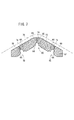
このように構成された中子10は、図2に示すように、第1型20及び第2型22によって形成されるキャビティ24の壁に配置される。勿論、各々の中子10の配置箇所は、第1石膏型に凹部を設けようとする部位である。
The
このキャビティ24に、石膏を充填する。石膏が固化することにより、図3に示す第1石膏型26が得られる。この第1石膏型26には、中子10の基盤部12に対応する正方形状の第1凹部28と、該第1凹部28に連通する第2凹部30とが形成される。勿論、第2凹部30は、中子10の胴体部14に対応する円柱形状凹部32と、該円柱形状凹部32に連通して前記椀形状部16の形状に対応する半球形状凹部34とからなる。すなわち、第1石膏型26には、中子10の形状が転写される。
The
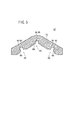
次に、この第1石膏型26を用いてキャビティを形成し、このキャビティにも石膏を充填する。石膏が固化することにより、図4に示す第2石膏型40が得られる。
Next, a cavity is formed using the
第2石膏型40には、第1石膏型26の第1凹部28及び第2凹部30に対応する第1凸部42及び第2凸部44が形成される。すなわち、第1凸部42は正方形状であり、一方の第2凸部44は、円柱形状凹部32に対応する円柱形状凸部46と、該円柱形状凸部46に連なる半球形状凸部48とからなる。このことから諒解されるように、第2石膏型40には第1石膏型26の凹部の形状に対応する形状が転写され、結局、中子10の形状に対応する凸部が形成される。
The
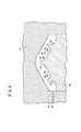
この第2石膏型40と、該第2石膏型40とは別途作製された成形型50とを用いてキャビティ52を形成する。なお、前記成形型50には、金属溶湯を流通させるためのランナ54が予め設けられており、且つキャビティ52に臨む端面には、シボ形状に対応する形状の転写部56が形成されている。
The
キャビティ52には、前記ランナ54を介して金属溶湯が充填される。ここで、金属溶湯の好適な例としては、JIS鋳造用アルミニウム合金であるAC3A、AC4A、AC4C、AC7A、AC8Aに代表されるアルミニウム合金の溶湯を挙げることができる。とりわけ、AC4Cは、収縮割れが生じ難い、気密性が高い、耐食性に優れる、流動性・充填性が良好である、溶接性に優れる等の種々の利点を有することから、真空成形用型の原材料として特に好適である。
The
キャビティ52に導入された金属溶湯は、第1凸部42及び第2凸部44が形成された部位に到達する。上記したように、第2凸部44の先端は半球形状凸部48であり、円弧状に湾曲している。このような湾曲部位に到達した金属溶湯では、平坦な部位に到達した金属溶湯に比して乱流が生じ難い。このため、半球形状凸部48の近傍で固化する金属溶湯に巣が生成することが回避される。
The molten metal introduced into the
そして、この金属溶湯を固化することにより、図5に示すように、第1凸部42及び第2凸部44に対応する形状の陥没60が形成された真空成形用型62が得られる。勿論、この陥没60は、第1凸部42に対応する正方形状陥没64と、第2凸部44に対応する円柱状陥没66及び半球形状陥没68とが連なった形態をなす。なお、真空成形用型62において、陥没60が形成されていない端面が成形面70となり、この成形面70には、前記成形型50の転写部56の形状が転写される。
Then, by solidifying the molten metal, as shown in FIG. 5, a
この中、半球形状陥没68の近傍には巣が生成していることがほとんど認められない。上記したように、半球形状凸部48の近傍では金属溶湯が流動することが容易であり、乱流が起こり難いからである。
Of these, almost no nests are found near the
以上のように、中子10に椀形状部16を設け、これにより第2石膏型40に半球形状凸部48を設けることにより、巣が生成することが抑制された真空成形用型62を得ることが可能となる。これに伴い、穿孔用工具で吸引用貫通孔を形成する際に従来から実施されていた座ぐり穴形成等の機械加工を削減することもできる。
As described above, by providing the core-shaped
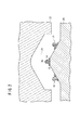
次に、図6に示すように、ドリル72等を用いて陥没60側から成形面70に向かって穿孔加工を施し、吸引用貫通孔74(図7参照)を形成する。この際、好ましくは半球形状陥没68からドリル72(図6参照)が埋入される。上記したように、半球形状陥没68の近傍では、巣が生成することが回避されている。このため、ドリル72が巣に引っかかることなく埋入するからである。従って、ドリル72が折れることも回避される。
Next, as shown in FIG. 6, drilling is performed from the
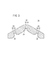
また、特許文献2の図1に示されるような平坦な天井面に対してドリル72の軸線が傾斜した状態で該ドリル72を埋入させると、ドリル72が折れる懸念がある。これに対し、本実施の形態のように半球形状陥没68の天井面に対してドリル72を埋入する場合、図8に示すように、ドリル72の軸線が若干傾斜していても、半球形状陥没68の天井面に対してドリル72の先端が略直交する状態で該ドリル72が埋入されることになる。従って、ドリル72が折れる懸念が払拭される。
Moreover, when the
すなわち、本実施の形態によれば、ドリル72等の穿孔用工具を損傷することを回避しながら、穿孔加工を効率よく進行させることができる。
That is, according to the present embodiment, it is possible to efficiently advance the drilling process while avoiding damaging the drilling tool such as the
しかも、第1石膏型26に凹部を形成するための中子10が樹脂であるので、安価に作製することができる。その上、第1石膏型26を形成するための第1型20及び第2型22と中子10とは別体であるので、第1石膏型26に形成される第1凹部28及び第2凹部30の位置を変更するためには中子10の位置を変更するのみでよい。すなわち、簡便な作業のみで第1石膏型26の凹部の位置を変更することが可能である。従って、真空成形用型62を作製するためのコストを低廉化することもできる。
And since the
このようにして作製された真空成形用型62は、図7に示すように、樹脂基材76を真空成形する際の型として用いられる。すなわち、先ず、該真空成形用型62に樹脂基材76が保持され、型締めがなされる。次に、前記吸引用貫通孔74及び前記陥没60を介してキャビテイ内のガスが吸引され、これにより該キャビテイ内が負圧となる。
The
これに伴い、該真空成形用型62に樹脂基材76が密着して真空成形用型62の形状に沿って微細に屈曲変形する。同時に、その表面に成形面70のシボ形状が転写され、所定の面形状及び屈曲率に成形された樹脂成形品が得られる。
Along with this, the
この吸引の際、吸引されるガスの流れに乱れが生じることも抑制される。この理由は、真空成形用型62に半球形状陥没68が形成されており、ガスがこの半球形状陥没68に沿って流れることによってガス流れが整えられるためであると推察される。
During this suction, the occurrence of turbulence in the flow of the sucked gas is also suppressed. The reason for this is presumed to be that a
すなわち、上記したように半球形状陥没68を有する真空成形用型62を作製することにより、真空成形の際に吸引を効率よく行えるという利点を得ることもできる。
That is, by producing the
なお、この実施の形態においては、半球形状陥没68に連なる円柱状陥没66を有する真空成形用型62を作製するようにしているが、円柱状陥没66に代替し、正方形状陥没64に向かってテーパ状に拡径するテーパ状陥没を設けるようにしてもよい。この場合、中子10として、胴体部14が基盤部12に向かうにつれて拡径するテーパ部であるものを使用すればよい。
In this embodiment, the
また、正方形状陥没64に連なる陥没は、半球形状陥没68に特に限定されるものではなく、天井面が円弧状に湾曲しながら縮径する陥没であればよい。
In addition, the depression continuous to the
さらに、第2石膏型40の第1凸部42は、正方形状以外の形状であってもよい。例えば、第1凸部42が円形状や楕円形状である場合、真空成形用型62を成形する際、該第1凸部42の近傍に到達した金属溶湯にも乱流が生じ難くなり、その結果、この部位で固化する金属溶湯にも巣が生成することが回避されるので好適である。
Furthermore, the first
いずれの場合においても、中子10に胴体部14を設ける必要は特になく、半球形状ないしは頂部に向かって湾曲した凸部のみが形成されたものであってもよい。勿論、この場合、真空成形用型62には、半球形状ないし天井面が円弧状に湾曲しながら縮径した陥没のみが形成される。
In any case, it is not particularly necessary to provide the
10…中子 12…基盤部
14…胴体部 16…椀形状部
26…第1石膏型 28…第1凹部
30…第2凹部 32…円柱形状凹部
34…半球形状凹部 40…第2石膏型
42…第1凸部 44…第2凸部
46…円柱形状凸部 48…半球形状凸部
50…成形型 52…キャビティ
54…ランナ 56…転写部
60…陥没 62…真空成形用型
64…正方形状陥没 66…円柱状陥没
68…半球形状陥没 70…成形面
72…ドリル 74…吸引用貫通孔
76…樹脂基材
DESCRIPTION OF
Claims (3)
先端になるにつれて湾曲しながら縮径する椀形状部を有する中子を配置したキャビティに石膏を充填し、前記椀形状部の形状が転写されることによって凹部が形成された第1石膏型を作製する工程と、
前記第1石膏型を用いて形成されるキャビティに石膏を充填し、前記凹部の形状が転写されることによって凸部が形成された第2石膏型を作製する工程と、
前記第2石膏型を用いて形成されるキャビティに金属溶湯を充填し、前記凸部の形状が転写されることによって前記椀形状部に対応する形状の陥没が形成された真空成形用型を作製する工程と、
前記成形面から前記陥没に至る前記吸引用貫通孔を設ける工程と、
を有することを特徴とする真空成形用型の製造方法。 A vacuum forming mold manufacturing method in which a suction through-hole is formed from the molding surface to the other end surface of vacuum forming,
A gypsum is filled in a cavity in which a core having a bowl-shaped part that is curled and reduced in diameter toward the tip is placed, and a first gypsum mold in which a recess is formed by transferring the shape of the bowl-shaped part is produced. And a process of
Filling a cavity formed using the first gypsum mold with gypsum, and producing a second gypsum mold having a convex portion formed by transferring the shape of the concave portion;
Filling the cavity formed using the second gypsum mold with molten metal, and producing the vacuum forming mold in which the shape of the projection is transferred to form a depression corresponding to the shape of the bowl And a process of
Providing the suction through hole from the molding surface to the depression;
A method for producing a vacuum forming mold, comprising:
前記真空成形用型に、前記椀形状部及び前記胴体部に対応する形状の陥没を形成することを特徴とする真空成形用型の製造方法。 2. The manufacturing method according to claim 1, wherein the core is connected to a portion having a maximum diameter in the flange-shaped portion, and a tapered portion that expands in a taper shape as the distance from the flange-shaped portion increases, or a columnar shape A body part consisting of any of the parts,
A method of manufacturing a vacuum forming mold, comprising forming a depression corresponding to the shape of the flange portion and the body portion in the vacuum forming die.
Priority Applications (1)
| Application Number | Priority Date | Filing Date | Title |
|---|---|---|---|
| JP2008005984A JP5048528B2 (en) | 2008-01-15 | 2008-01-15 | Manufacturing method of vacuum forming mold |
Applications Claiming Priority (1)
| Application Number | Priority Date | Filing Date | Title |
|---|---|---|---|
| JP2008005984A JP5048528B2 (en) | 2008-01-15 | 2008-01-15 | Manufacturing method of vacuum forming mold |
Publications (2)
| Publication Number | Publication Date |
|---|---|
| JP2009166328A true JP2009166328A (en) | 2009-07-30 |
| JP5048528B2 JP5048528B2 (en) | 2012-10-17 |
Family
ID=40968081
Family Applications (1)
| Application Number | Title | Priority Date | Filing Date |
|---|---|---|---|
| JP2008005984A Expired - Fee Related JP5048528B2 (en) | 2008-01-15 | 2008-01-15 | Manufacturing method of vacuum forming mold |
Country Status (1)
| Country | Link |
|---|---|
| JP (1) | JP5048528B2 (en) |
-
2008
- 2008-01-15 JP JP2008005984A patent/JP5048528B2/en not_active Expired - Fee Related
Also Published As
| Publication number | Publication date |
|---|---|
| JP5048528B2 (en) | 2012-10-17 |
Similar Documents
| Publication | Publication Date | Title |
|---|---|---|
| WO2008105461A1 (en) | Core for thin-wall hollow casting and thin-wall hollow casting produced by production method employing it | |
| JP2014091263A (en) | Composite molding | |
| CN106660284A (en) | Patterns with textured inserts for the manufacture of textured molds for molding and vulcanizing tires | |
| US20150118057A1 (en) | Multi-wall gas turbine airfoil cast using a ceramic core formed with a fugitive insert and method of manufacturing same | |
| JP5048528B2 (en) | Manufacturing method of vacuum forming mold | |
| CN105522115A (en) | Feeding device and system and high pressure modeling method | |
| CN100503084C (en) | Manufacturing method of supporting structure for vehicle | |
| JP5092987B2 (en) | Manufacturing method of tire vulcanization mold | |
| JP5414009B2 (en) | Mold for resin molding, resin molding method and resin molded product | |
| CN105637205B (en) | Cylinder block and its manufacturing method | |
| EP3610967A1 (en) | Method for forming cooling holes having separate complex and simple geometry sections | |
| JP4033165B2 (en) | Casting cap nut and casting method using cast cap nut | |
| JP2019206020A (en) | Support structure for vehicle and method for producing the same | |
| JP6629588B2 (en) | Die-casting mold, cast product produced using die-casting mold, and method for producing cast product using die-casting mold | |
| JP2017170469A (en) | Casting apparatus and casting product manufacturing method | |
| JP2011110559A (en) | Degassing device for casting device and degassing method | |
| CN217252615U (en) | Easy-cutting piece with groove at bottom | |
| JP5407519B2 (en) | Manufacturing method of hollow casting | |
| JP5376286B2 (en) | Casting mold cooling structure | |
| JP4210570B2 (en) | Casting method and cast parts | |
| JP2009006371A (en) | Mold | |
| JP2010221515A (en) | Mold for in-mold coating | |
| JP2012086874A (en) | Packaging machine former | |
| JP2007283498A (en) | Mold and degassing method | |
| JP5691480B2 (en) | Die-cast overflow shape |
Legal Events
| Date | Code | Title | Description |
|---|---|---|---|
| A621 | Written request for application examination |
Free format text: JAPANESE INTERMEDIATE CODE: A621 Effective date: 20101126 |
|
| A977 | Report on retrieval |
Free format text: JAPANESE INTERMEDIATE CODE: A971007 Effective date: 20120531 |
|
| TRDD | Decision of grant or rejection written | ||
| A01 | Written decision to grant a patent or to grant a registration (utility model) |
Free format text: JAPANESE INTERMEDIATE CODE: A01 Effective date: 20120626 |
|
| A01 | Written decision to grant a patent or to grant a registration (utility model) |
Free format text: JAPANESE INTERMEDIATE CODE: A01 |
|
| A61 | First payment of annual fees (during grant procedure) |
Free format text: JAPANESE INTERMEDIATE CODE: A61 Effective date: 20120719 |
|
| FPAY | Renewal fee payment (event date is renewal date of database) |
Free format text: PAYMENT UNTIL: 20150727 Year of fee payment: 3 |
|
| R150 | Certificate of patent or registration of utility model |
Free format text: JAPANESE INTERMEDIATE CODE: R150 |
|
| LAPS | Cancellation because of no payment of annual fees |