JP2009166321A - Mold for foam molding and method of foam molding - Google Patents
Mold for foam molding and method of foam molding Download PDFInfo
- Publication number
- JP2009166321A JP2009166321A JP2008005861A JP2008005861A JP2009166321A JP 2009166321 A JP2009166321 A JP 2009166321A JP 2008005861 A JP2008005861 A JP 2008005861A JP 2008005861 A JP2008005861 A JP 2008005861A JP 2009166321 A JP2009166321 A JP 2009166321A
- Authority
- JP
- Japan
- Prior art keywords
- mold
- blade
- gas passage
- foam molding
- cavity
- Prior art date
- Legal status (The legal status is an assumption and is not a legal conclusion. Google has not performed a legal analysis and makes no representation as to the accuracy of the status listed.)
- Pending
Links
- 238000010097 foam moulding Methods 0.000 title claims abstract description 37
- 238000000034 method Methods 0.000 title abstract description 10
- 238000005520 cutting process Methods 0.000 claims abstract description 36
- 238000000465 moulding Methods 0.000 claims abstract description 6
- XEEYBQQBJWHFJM-UHFFFAOYSA-N Iron Chemical compound [Fe] XEEYBQQBJWHFJM-UHFFFAOYSA-N 0.000 claims description 20
- 239000011347 resin Substances 0.000 claims description 12
- 229920005989 resin Polymers 0.000 claims description 12
- 229920005830 Polyurethane Foam Polymers 0.000 claims description 10
- 229910052742 iron Inorganic materials 0.000 claims description 10
- 239000011496 polyurethane foam Substances 0.000 claims description 10
- 230000013011 mating Effects 0.000 claims description 9
- 238000005187 foaming Methods 0.000 claims description 6
- 229910045601 alloy Inorganic materials 0.000 claims description 5
- 239000000956 alloy Substances 0.000 claims description 5
- 229910001234 light alloy Inorganic materials 0.000 claims description 5
- JOYRKODLDBILNP-UHFFFAOYSA-N Ethyl urethane Chemical compound CCOC(N)=O JOYRKODLDBILNP-UHFFFAOYSA-N 0.000 abstract description 14
- 239000006260 foam Substances 0.000 abstract description 10
- 239000007789 gas Substances 0.000 abstract 5
- 238000000926 separation method Methods 0.000 abstract 1
- 229910052751 metal Inorganic materials 0.000 description 9
- 239000002184 metal Substances 0.000 description 9
- 239000011550 stock solution Substances 0.000 description 5
- CURLTUGMZLYLDI-UHFFFAOYSA-N Carbon dioxide Chemical compound O=C=O CURLTUGMZLYLDI-UHFFFAOYSA-N 0.000 description 4
- 238000003780 insertion Methods 0.000 description 3
- 230000037431 insertion Effects 0.000 description 3
- 230000002093 peripheral effect Effects 0.000 description 3
- 229910000838 Al alloy Inorganic materials 0.000 description 2
- 229910052782 aluminium Inorganic materials 0.000 description 2
- XAGFODPZIPBFFR-UHFFFAOYSA-N aluminium Chemical compound [Al] XAGFODPZIPBFFR-UHFFFAOYSA-N 0.000 description 2
- 229910002092 carbon dioxide Inorganic materials 0.000 description 2
- 239000001569 carbon dioxide Substances 0.000 description 2
- 238000006243 chemical reaction Methods 0.000 description 2
- 238000007599 discharging Methods 0.000 description 2
- 239000000463 material Substances 0.000 description 2
- 229910000831 Steel Inorganic materials 0.000 description 1
- 238000010521 absorption reaction Methods 0.000 description 1
- PCHJSUWPFVWCPO-UHFFFAOYSA-N gold Chemical compound [Au] PCHJSUWPFVWCPO-UHFFFAOYSA-N 0.000 description 1
- 239000010931 gold Substances 0.000 description 1
- 229910052737 gold Inorganic materials 0.000 description 1
- 239000006082 mold release agent Substances 0.000 description 1
- 230000000149 penetrating effect Effects 0.000 description 1
- 239000010959 steel Substances 0.000 description 1
Images


Landscapes
- Moulds For Moulding Plastics Or The Like (AREA)
Abstract
Description
本発明は、ポリウレタンフォーム等の樹脂発泡成形品を製造するための金型に係り、特にキャビティからのガス排出用のガス通路を有する発泡成形用の金型に関する。また、本発明は、この金型を用いた発泡成形方法に関するものである。 The present invention relates to a mold for producing a resin foam molded article such as polyurethane foam, and more particularly to a foam mold having a gas passage for discharging gas from a cavity. The present invention also relates to a foam molding method using this mold.
自動車シート用の軟質ポリウレタンフォームや、自動車のドアトリムに取り付けられた、側面衝突(側突)時の衝撃エネルギー吸収(Energy Absorption:EA)のための硬質ポリウレタンフォームよりなるEA材などの発泡成形は、金型内でウレタン原液を発泡させて成形される。この金型は、上型及び下型を備えており、該下型内にウレタン原液を供給し、型締めして発泡させ、硬化(キュア)後に型開きして脱型を行う。 Foam molding such as soft polyurethane foam for automobile seats and EA material made of rigid polyurethane foam for energy absorption (EA) at the time of side impact (side impact) attached to the door trim of automobiles, Molded by foaming urethane stock solution in the mold. This mold includes an upper mold and a lower mold. A urethane stock solution is supplied into the lower mold, the mold is clamped and foamed, and after curing (curing), the mold is opened and demolded.
このウレタン等の発泡成形に際しては、キャビティ内の空気や、反応時に発生する炭酸ガス等の気体(以下これらをガスという。)をガス通路を介して金型外に排出する。 In the foam molding of urethane or the like, air in the cavity or gas such as carbon dioxide gas generated during the reaction (hereinafter referred to as gas) is discharged out of the mold through the gas passage.
特開2003−19718号には、キャビティ内のガスを金型合わせ面PLに設けた溝部を介して排気することにより、その他の合わせ面PLにおいて薄いバリが発生することを防止する成形方法及び装置が記載されている。
上記特開2003−19718号の金型によって発泡成形を行うと、上記の溝部(ガス通路)に比較的厚いバリが生じることになる。このバリは、脱型後に除去する必要がある。 When foam molding is performed using the mold disclosed in Japanese Patent Application Laid-Open No. 2003-19718, a relatively thick burr is generated in the groove (gas passage). This burr needs to be removed after demolding.
本発明は、このようなガス通路に生じたバリを切断分離する切断装置を備えており、脱型後の該バリの切断分離作業を不要とすることができる発泡成形用の金型及びその成形方法を提供することを目的とする。 The present invention is equipped with a cutting device that cuts and separates burrs generated in such gas passages, and a mold for foam molding that can eliminate the work of cutting and separating the burrs after demolding and the molding thereof. It aims to provide a method.
請求項1の発泡成形用の金型は、型締めされる少なくとも第1の型と第2の型とを有する、樹脂成形品の発泡成形用の金型であって、キャビティ内のガスを金型外に流出させるガス通路を有しており、該ガス通路の少なくとも一部は、前記第1の型と第2の型との合わせ面に沿って設けられている発泡成形用の金型において、該ガス通路内で生じたバリをキャビティ内の成形品から切断分離する刃を有する切断装置を設けたことを特徴とするものである。 The mold for foam molding according to claim 1 is a mold for foam molding of a resin molded product having at least a first mold and a second mold to be clamped, and the gas in the cavity is made of gold. A gas passage for flowing out of the mold, and at least a part of the gas passage is a mold for foam molding provided along a mating surface of the first mold and the second mold; A cutting device having a blade for cutting and separating burrs generated in the gas passage from a molded product in the cavity is provided.
請求項2の発泡成形用の金型は、請求項1において、該第1の型は上型であり、第2の型は下型であり、前記刃は該上型に設けられていることを特徴とするものである。
The foam molding mold according to
請求項3の発泡成形用の金型は、請求項2において、前記ガス通路は、前記上型又は下型の合わせ面に設けられた溝よりなり、前記刃は、該溝内に突出した状態と上型内に後退した状態とをとりうるように進退可能であり、前記切断装置は、該刃を進退させる駆動装置を備えてなることを特徴とするものである。
The mold for foam molding according to
請求項4の発泡成形用の金型は、請求項3において、前記刃に対峙して刃受けが設けられていることを特徴とするものである。 According to a fourth aspect of the present invention, there is provided a metal mold for foam molding according to the third aspect, wherein a blade receiver is provided opposite to the blade.
請求項5の発泡成形用の金型は、請求項4において、前記上型及び下型は軽合金製であり、刃受けは鉄又は鉄基合金製であることを特徴とするものである。 According to a fifth aspect of the present invention, there is provided a mold for foam molding according to the fourth aspect, wherein the upper mold and the lower mold are made of a light alloy, and the blade receiver is made of iron or an iron-based alloy.
請求項6の発泡成形方法は、請求項1ないし5のいずれか1項に記載の発泡成形用の金型を用いた発泡成形方法であって、型開き前に前記刃によってガス通路内のバリをキャビティ内の成形品と切断分離することを特徴とするものである。 A foam molding method according to a sixth aspect is a foam molding method using the foam molding die according to any one of the first to fifth aspects, wherein a burr in the gas passage is formed by the blade before the mold is opened. Is cut and separated from the molded product in the cavity.
請求項7の発泡成形方法は、請求項6において、ポリウレタンフォームを発泡成形する方法であって、発泡終了後、硬化前にバリを切断分離することを特徴とするものである。 A foam molding method according to a seventh aspect is the method of foam molding of the polyurethane foam according to the sixth aspect, wherein the burr is cut and separated after the foaming and before the curing.
本発明の金型を用いて発泡成形を行う場合、キャビティ内のガスがガス通路を介して金型外に排出される。キャビティ内のガスの全量が排出された後は、キャビティ内の樹脂材料の一部もガス通路内に入り込み、バリとなる。本発明では、このバリを切断装置で切断分離するため、脱型時には、このバリが分離された成形品が得られる。 When foam molding is performed using the mold of the present invention, the gas in the cavity is discharged out of the mold through the gas passage. After the entire amount of gas in the cavity is exhausted, part of the resin material in the cavity also enters the gas passage and becomes a burr. In the present invention, since this burr is cut and separated by a cutting device, a molded product from which this burr is separated is obtained at the time of demolding.
なお、キャビティ内の樹脂がガス通路に入り込むことにより、ガス通路以外の部分の金型合わせ面への樹脂の侵入が防止され、ガス通路以外の箇所で薄いバリが発生することも防止される。 In addition, when the resin in the cavity enters the gas passage, the resin can be prevented from entering the mold mating surface at portions other than the gas passage, and thin burrs can be prevented from being generated at locations other than the gas passage.
請求項2の通り、この切断装置の刃を上型に設けることにより、下型から脱型を行う際に刃が脱型作業に影響しないものとなる。
By providing the blade of this cutting device in the upper die as in
請求項3の通り、この刃を、上型に対し進退可能に設け、駆動装置によって進退させ、後退時には上型内に後退させるよう構成することにより、型締めや型開きなどの成形作業に刃が支障とならず、作業効率が向上する。
According to
請求項4の通り、刃受けを設けておくことにより、刃が当って刃受けが損耗しても、刃受けのみを交換することができる。
As described in
なお、金型は、通常、アルミニウム、アルミニウム合金などの軽合金製とされるが、刃受けについては、請求項5の通り、硬度が高い鉄又は鉄基合金製とするのが好ましい。
The mold is usually made of a light alloy such as aluminum or an aluminum alloy. However, the blade support is preferably made of iron or an iron-based alloy having high hardness as described in
ポリウレタンフォームを発泡成形する場合は、バリを切断するタイミングとしては、請求項7の通り、発泡終了後、硬化前が好適である。このようにフォームが硬化する前であれば、刃によってバリを容易に切断することができる。
When foaming a polyurethane foam, the timing for cutting the burrs is preferably after foaming and before curing as described in
以下、図面を参照して実施の形態について説明する。 Hereinafter, embodiments will be described with reference to the drawings.
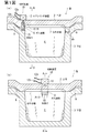
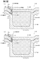
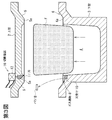
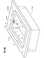
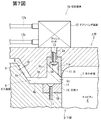
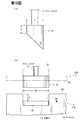
第1図(a)は、実施の形態に係る樹脂成形品発泡成形用金型の縦断面図(第1図(b)のA−A線に沿う断面図)、第1図(b)は第1図(a)のB−B線に沿う断面図、第2図(a)はこの金型の発泡成形時における断面図、第2図(b)はこの金型のバリ切断時における断面図、第3図はこの金型の脱型時における分解図(断面図)、第4図及び第5図は上型の下面側からの斜視図、第6図は下型の上面側からの斜視図、第7図及び第8図はこの金型のバリ切断装置付近の断面図、第9図(a)はこの切断装置の刃の側面図、第9図(b)はこの刃及び下型のガス通路付近のキャビティ側からの正面図である。 FIG. 1 (a) is a longitudinal sectional view (cross-sectional view taken along the line AA of FIG. 1 (b)) of the mold for resin-molded article foam molding according to the embodiment, and FIG. 1A is a cross-sectional view taken along line B-B in FIG. 1, FIG. 2A is a cross-sectional view of the mold during foam molding, and FIG. 2B is a cross-section of the mold during burr cutting. FIGS. 3 and 3 are exploded views (cross-sectional views) of the mold when removed, FIGS. 4 and 5 are perspective views from the lower surface side of the upper die, and FIG. 6 is an upper surface side of the lower die. FIGS. 7 and 8 are cross-sectional views of the mold near the burr cutting device, FIG. 9A is a side view of the blade of the cutting device, and FIG. 9B is the blade and the bottom. It is a front view from the cavity side of the gas passage vicinity of a type | mold.
なお、第2図(a),(b)はそれぞれ第1図(a)と同様部分の断面にて示されている。第4図は刃後退時を示し、第5図は刃突出時を示している。第7図はガス通路に発泡樹脂が侵入する前の状態を示し、第8図はガス通路に侵入した発泡樹脂を切断した状態を示している。 2 (a) and 2 (b) are each shown in a cross section similar to FIG. 1 (a). FIG. 4 shows the time of blade retraction, and FIG. 5 shows the time of blade protrusion. FIG. 7 shows a state before the foamed resin enters the gas passage, and FIG. 8 shows a state where the foamed resin that has entered the gas passage is cut.
この実施の形態では、金型により発泡成形される樹脂成形品はポリウレタンフォームであるが、本発明の金型及び発泡成形方法は、これ以外の樹脂成形品の発泡成形にも適用可能である。 In this embodiment, the resin molded product foam-molded by the mold is polyurethane foam, but the mold and the foam molding method of the present invention can be applied to foam molding of other resin molded products.
この実施の形態の金型1は、第1の型としての上型2と、第2の型としての下型3とからなり、該下型3内に凹所よりなるキャビティ4が設けられている。上型2の下面には、このキャビティ4の周縁部に沿って凸条5が周設され、キャビティ4の周縁部には、この凸条5が係合する凹段部6が周設されている。第3,6図のように、この凹段部6は、キャビティ4内に臨んでいる。
The mold 1 of this embodiment includes an
この金型1においては、第1図(a),(b)のように、該合わせ面7に沿って、キャビティ4内のガスを金型1外に排出するためのガス通路8が設けられている。
In the mold 1, as shown in FIGS. 1A and 1B, a
この実施の形態では、該ガス通路8は、第6図に示すように、下型3の凹段部6の底面6aに設けられた溝6bよりなる。この溝6bは、該底面6aを金型内外方向に横切って延設されており、一端側はキャビティ4内に臨み、他端側は凹段部6の側周面6cの下端に臨んでいる。第9図(b)に示すように、この溝6bの底面は、凹段部6の底面6aと略平行な平坦面となっている。上型2を下型3に型締めした状態においては、この溝6bに重なった上型2の凸条5の下端面5aと、この溝6bの両側面及び底面とによって囲まれた空間が前記ガス通路8となる。
In this embodiment, the
この実施の形態では、上型2及び下型3は、それぞれ、アルミニウム又はアルミニウム合金等の軽合金製となっている。
In this embodiment, the
この金型1は、該ガス通路8内に生じたバリBをキャビティ4内のポリウレタンフォーム(以下、フォームと略すことがある。)F即ち成形品から切断分離するための刃11を有した切断装置10を備えている。以下に、この切断装置10の構成について詳述する。
The mold 1 has a
第4,5図及び第7,8図の通り、上型2の凸条5の下端面5aには、該下端面5aから上方へ凹陥した凹穴よりなる刃収容部5bが設けられている。この刃収容部5bは、上型2を下型3に型締めした状態においては、前記溝6bに臨んでいる。前記刃11は、該溝6b内に突出した状態とこの刃収容部5b内に後退した状態とをとりうるように、この刃収容部5b内に上下方向進退可能に設置されている。
As shown in FIGS. 4, 5 and 7, 8, the
なお、この実施の形態では、該刃11は鋼製である。
In this embodiment, the
この刃11の金型内外方向と交叉方向の幅は、第9図(b)に示すように、溝6bの幅W2と略同等かそれよりも若干小さい幅(刃11が溝6b内に進退可能であり、且つ刃11が溝6b内に突出した状態において、実質的に該刃11の側面と溝6bの側面との間をウレタン原液が通過し得ない程度の幅)となっている。また、この刃11の下端辺(刃先)は、溝6bの底面と略平行となっている。即ち、刃11が溝6b内に突出すると、この刃11の刃先が溝6bの略全幅にわたって該溝6bの底面に当接するようになっている。
Die-out direction and cross direction of the width of the
この実施の形態では、第7,8図に示すように、該刃11のキャビティ4側の面(以下、前面という。)と、これと反対側の面(以下、後面という。)とがそれぞれ溝6bの底面と略直交する略鉛直面となっており、下面は、該前面側から後面側へ上り勾配となっている。即ち、この刃11の前面の下縁がこの刃11の刃先となっている。
In this embodiment, as shown in FIGS. 7 and 8, the
この刃11の金型内外方向の厚みT(第9図(a))は5〜0.1mm、特に2〜1mmであることが好ましく、この刃11の前面と下面との交叉角θ(第9図(a))は10〜80°、特に35〜55°であることが好ましい。例えばこの実施の形態では、刃11は、その金型内外方向の厚みTが1.0mmとされ、後面の上下方向の幅Hが5mmとされ、前面と下面との交叉角θが45°とされている。
The thickness T (FIG. 9 (a)) of the
この刃11を収容した刃収容部5bの奥行き(即ち上型2の凸条5の下端面5aから該刃収容部5bの天井面までの鉛直方向の距離)は、この刃11の前面の上下方向の幅と同等かそれよりも大きなものとなっており、刃11が該刃収容部5b内に後退した状態にあっては、この刃11の刃先が凸条5の下端面5aから突出しないようになっている。
The depth of the
本発明においては、刃11が溝6b内に突出したときに、この刃11の刃先が該溝6bの底面とキャビティ4の内面との交叉角縁に当接することが最も好ましいが、第7,8図のように、それよりも若干、ガス通路8の奥側において刃先が溝6bの底面に当接するように構成されていてもよい。
In the present invention, when the
切断装置10は、この刃11を溝6b内に進退させる駆動装置としてのエアシリンダ装置12を備えている。このエアシリンダ装置12は、コンプレッサ(図示略)からのガス圧により、プッシュロッド13を進退させるものである。第7,8図の符号12a,12bは、それぞれ、このエアシリンダ装置12に接続された給気用及び排気用のホースを示している。
The cutting
第7,8図に示すように、この実施の形態では、該エアシリンダ装置12は上型2の上面に設置されており、この上型2の上面から前記刃収容部5bの天井面にまで貫通したプッシュロッド挿通孔2aを通ってプッシュロッド13が該刃収容部5b内に上下方向進退可能に挿入されている。このプッシュロッド13の下端に、刃11がビス14によって着脱可能に取り付けられている。即ち、この実施の形態では、該刃11は交換可能となっている。
As shown in FIGS. 7 and 8, in this embodiment, the
なお、この実施の形態では、第7,8図の通り、刃11の下面にはビス14の頭部を収容する凹部11aが形成されており、刃11の上面には、プッシュロッド13の下端部が係合する凹部(符号略)が設けられている。この刃11の下面側の凹部11aの天井面には、該刃11の上面側の凹部の底面にまで貫通するビス挿通孔(符号略)が設けられている。また、プッシュロッド13の下端面には雌ねじ孔(符号略)が設けられている。
In this embodiment, as shown in FIGS. 7 and 8, the lower surface of the
刃11をプッシュロッド13に取り付ける場合には、刃11を刃収容部5bに挿入し、プッシュロッド13の下端部を該刃11の上面側の凹部に係合させる。そして、該刃11の下面側の凹部11a及びビス挿通孔を介して該刃11の下面側からプッシュロッド13の雌ねじ孔にビス14を締め込み、刃11を固定する。第7,8図の通り、このビス14の頭部は刃11の下面側の凹部11a内に収容されるため、刃11の下面から下方へ突出しないものとなる。
When attaching the
刃11を交換する場合には、このビス14を緩めて古い刃11をプッシュロッド13から取り外し、上記の手順で新しい刃11をプッシュロッド13にビス14留めする。
When replacing the
なお、刃11のプッシュロッド13への取付方法はこれに限定されない。
In addition, the attachment method of the
この実施の形態では、下型3の溝6bの底面に、この刃11に対峙して刃受け15が設けられている。この刃受け15は、鉄又は鉄基合金製である。即ち、この実施の形態では、下型3の大部分は加工が容易な軽合金製となっており、刃11に対峙する刃受け15は硬度の高い鉄又は鉄基合金製となっている。
In this embodiment, a
この刃受け15は下型3と別体に製造されている。この実施の形態では、下型3には、溝6bの底面とキャビティ4の内面との交叉角部を切り欠くようにして凹段状の刃受け取付座16が形成されている。刃受け15は、この刃受け取付座16に嵌め込まれ、ビス17により着脱可能に該刃受け取付座16に固定されている。即ち、この実施の形態では、該刃受け15も交換可能となっている。
The
第7,8図の通り、この刃受け15の上面は溝6bの底面と略面一状となっている。また、この実施の形態では、刃受け取付座16はキャビティ4内に臨んでおり、刃受け15のキャビティ4側面もキャビティ4内に臨んでいる。この刃受け15のキャビティ4側面は、キャビティ4の内面と略面一となっている。即ち、この実施の形態では、刃受け15は、溝6bの底面とキャビティ4の内面との交叉角縁まで延在したものとなっている。
As shown in FIGS. 7 and 8, the upper surface of the
なお、この実施の形態では、前記ビス17として皿ビスを用いている。このビス17は、刃受け15の上面からねじ込まれており、このビス17で刃受け15を刃受け取付座16に固定した状態においては、第7,8図の如く、このビス17の頭部の上面は刃受け15の上面と略面一か又はそれよりも若干低位となっている。
In this embodiment, a countersunk screw is used as the
このように構成された金型1によって成形を行う手順について以下に説明する。 A procedure for molding with the mold 1 configured as described above will be described below.
この実施の形態では、金型1を型開きするに際しては、予め、切断装置10のエアシリンダ装置12を後退作動させて刃11を刃収容部5b内に後退させておく。
In this embodiment, when the mold 1 is opened, the
この金型1によって成形を行うには、型開き状態で上型2及び下型3のキャビティ4の内面並びにガス通路8の内面に離型剤を塗った後、キャビティ4内にウレタン原液を注入し、上型2を下型3に型締めし、金型1を加熱して該ウレタン原液を発泡させる。
In order to perform molding with the mold 1, a mold release agent is applied to the inner surfaces of the
この際、キャビティ4内のガス(キャビティ4内の空気や、ウレタン反応時に発生する炭酸ガス等の気体)がガス通路8及び間隙9を通って金型1外に排出される。
At this time, gas in the cavity 4 (air in the
そして、ウレタンが十分に発泡してキャビティ4内が発泡ウレタンで満たされ、キャビティ4内のガスの全量が金型1外に排出されると、第2図(a)のように、ウレタンの一部がガス通路8内に入り込み、バリBとなる。
Then, when the urethane is sufficiently foamed and the inside of the
なお、このようにキャビティ4内のウレタンがガス通路8に入り込むことにより、ガス通路8以外の部分の合わせ面7へのウレタンの侵入が防止され、ガス通路8以外の箇所で薄いバリが発生することが防止される。
In this way, the urethane in the
その後、切断装置10のエアシリンダ装置12を突出作動させ、第2図(b)及び第8図の如く刃11をガス通路8(溝6b)内に突出させてバリBをキャビティ4内のフォームFから切断分離する。なお、この実施の形態では、前述の通り、刃11の前面の下縁に沿ってこの刃11の刃先が形成されており、且つこの刃11の刃先は、溝6bの底面のうち、そのキャビティ4の内面との交叉角縁又はその近傍に当接するので、バリBをその根元又はごく根元に近い部分で切断することができる。
Thereafter, the
このバリBを切断するタイミングとしては、キャビティ4内のフォームFの発泡終了後、硬化前が好適である。これよりも早いと、ガスの排出が不十分でガス通路8内にバリBが生じておらず、これよりも遅いと、バリBが硬くなりすぎて切断するのが困難になる。
The timing for cutting the burr B is preferably after the foaming of the foam F in the
このようにフォームFが硬化する前であれば、刃11によってバリBを容易に切断することができる。
In this way, the burrs B can be easily cut by the
キャビティ4内のフォームFが硬化した後、エアシリンダ装置12を後退作動させて刃11を刃収容部5b内に後退させる。その後、第3図のように、上型2と下型3とを型開きし、キャビティ4内からフォームFを取り出すと共に、ガス通路8内からバリBを取り出す。これにより、既にバリBが切断分離されたポリウレタンフォームF即ち成形品が得られる。従って、脱型後にこのポリウレタンフォームFからバリBを除去する作業が不要である。
After the foam F in the
なお、この実施の形態では、切断装置10の刃11を上型2に配置しているので、下型3から脱型を行う際にこの刃11が脱型作業に影響しない。
In this embodiment, since the
また、この実施の形態では、刃11を上型2の刃収容部5b内に後退させておくことができるので、型締めや型開き作業を行う際にこの刃11が支障とならず、作業効率が向上する。
In this embodiment, since the
この実施の形態では、刃11及び刃受け15がそれぞれ交換可能となっているので、バリBの切断作業によりこれらが損耗しても、刃11及び刃受け15のみをそれぞれ交換することができる。
In this embodiment, since the
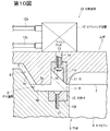
なお、この実施の形態では、刃受け15は、溝6b(ガス通路8)の底面とキャビティ4の内面との交叉角縁まで延在したものとなっているが、刃受け15の構成はこれに限定されない。即ち、本発明においては、第10図に示すように、刃受け15は、溝6bの底面とキャビティ4の内面との交叉角縁よりも若干、ガス通路8の奥側に後退している構成であってもよい。
In this embodiment, the
第10図は、刃受け15の別の構成例を示す、第7図と同様部分の断面図である。
FIG. 10 is a cross-sectional view of the same part as FIG. 7, showing another configuration example of the
この第10図の実施の形態では、溝6bの底面のうち、キャビティ4の内面との交叉角縁よりもガス通路8の奥側に、凹穴状の刃受け取付座16Aが形成されている。そのため、この実施の形態では、この刃受け取付座16Aに嵌め込まれた刃受け15は、溝6bの底面とキャビティ4の内面との交叉角縁よりもガス通路8の奥側に配置され、そのキャビティ4側の辺縁は、該交叉角縁からガス通路8の奥側に離隔している。
In the embodiment of FIG. 10, a recessed-blade blade
このように刃受け15が溝6bの底面とキャビティ4の内面との交叉角縁よりもガス通路8の奥側に配置される場合、刃受け15のキャビティ4側の面をキャビティ4の内面の形状に合わせて加工する必要がないため、刃受け15として汎用品を用いることができ、金型コストの低減を図ることができる。
As described above, when the
上記実施の形態はいずれも本発明の一例であり、本発明は上記以外の形態をもとりうる。 Each of the above embodiments is an example of the present invention, and the present invention may take other forms.
例えば、成形品の形状は図示以外でもよい。 For example, the shape of the molded product may be other than illustrated.
1 金型
2 上型
3 下型
4 キャビティ
5 凸条
5b 刃収容部
6 凹段部
6b 溝
7 合わせ面
8 ガス通路
10 切断装置
11 刃
12 エアシリンダ装置
13 プッシュロッド
15 刃受け
B バリ
DESCRIPTION OF SYMBOLS 1
Claims (7)
キャビティ内のガスを金型外に流出させるガス通路を有しており、該ガス通路の少なくとも一部は、前記第1の型と第2の型との合わせ面に沿って設けられている発泡成形用の金型において、
該ガス通路内で生じたバリをキャビティ内の成形品から切断分離する刃を有する切断装置を設けたことを特徴とする発泡成形用の金型。 A mold for foam molding of a resin molded product having at least a first mold and a second mold to be clamped,
A gas passage for allowing the gas in the cavity to flow out of the mold is provided, and at least a part of the gas passage is provided along the mating surface of the first mold and the second mold. In the mold for molding,
A mold for foam molding comprising a cutting device having a blade for cutting and separating burrs generated in the gas passage from a molded product in the cavity.
前記切断装置は、該刃を進退させる駆動装置を備えてなることを特徴とする発泡成形用の金型。 3. The gas passage according to claim 2, wherein the gas passage includes a groove provided on a mating surface of the upper die or the lower die, and the blade can take a state of protruding into the groove and a state of retreating into the upper die. Can be advanced and retracted
The die for foam molding, wherein the cutting device includes a drive device for moving the blade back and forth.
型開き前に前記刃によってガス通路内のバリをキャビティ内の成形品と切断分離することを特徴とする発泡成形方法。 A foam molding method using the mold for foam molding according to any one of claims 1 to 5,
A foam molding method characterized in that the burrs in the gas passage are cut and separated from the molded product in the cavity by the blade before opening the mold.
Priority Applications (1)
| Application Number | Priority Date | Filing Date | Title |
|---|---|---|---|
| JP2008005861A JP2009166321A (en) | 2008-01-15 | 2008-01-15 | Mold for foam molding and method of foam molding |
Applications Claiming Priority (1)
| Application Number | Priority Date | Filing Date | Title |
|---|---|---|---|
| JP2008005861A JP2009166321A (en) | 2008-01-15 | 2008-01-15 | Mold for foam molding and method of foam molding |
Publications (1)
| Publication Number | Publication Date |
|---|---|
| JP2009166321A true JP2009166321A (en) | 2009-07-30 |
Family
ID=40968077
Family Applications (1)
| Application Number | Title | Priority Date | Filing Date |
|---|---|---|---|
| JP2008005861A Pending JP2009166321A (en) | 2008-01-15 | 2008-01-15 | Mold for foam molding and method of foam molding |
Country Status (1)
| Country | Link |
|---|---|
| JP (1) | JP2009166321A (en) |
Cited By (4)
| Publication number | Priority date | Publication date | Assignee | Title |
|---|---|---|---|---|
| JP2010023466A (en) * | 2008-07-24 | 2010-02-04 | Toyota Boshoku Corp | Method of molding fiber substrate and molding device |
| WO2016139091A1 (en) * | 2015-03-02 | 2016-09-09 | Polytec Car Styling Hörsching GmbH | Foaming and punching tool and method for producing foamed products |
| CN111319167A (en) * | 2020-03-09 | 2020-06-23 | 张军堂 | Plastic product forming die |
| CN118544444A (en) * | 2024-05-06 | 2024-08-27 | 浙江江山朗众新材料科技有限公司 | A device and method for collecting molded scraps |
-
2008
- 2008-01-15 JP JP2008005861A patent/JP2009166321A/en active Pending
Cited By (5)
| Publication number | Priority date | Publication date | Assignee | Title |
|---|---|---|---|---|
| JP2010023466A (en) * | 2008-07-24 | 2010-02-04 | Toyota Boshoku Corp | Method of molding fiber substrate and molding device |
| WO2016139091A1 (en) * | 2015-03-02 | 2016-09-09 | Polytec Car Styling Hörsching GmbH | Foaming and punching tool and method for producing foamed products |
| US10688691B2 (en) | 2015-03-02 | 2020-06-23 | Polytec Car Styling Hörsching GmbH | Foaming and punching tool and method for producing foamed products |
| CN111319167A (en) * | 2020-03-09 | 2020-06-23 | 张军堂 | Plastic product forming die |
| CN118544444A (en) * | 2024-05-06 | 2024-08-27 | 浙江江山朗众新材料科技有限公司 | A device and method for collecting molded scraps |
Similar Documents
| Publication | Publication Date | Title |
|---|---|---|
| JP2012224068A (en) | Injection molding machine and injection molding method | |
| JP2009166321A (en) | Mold for foam molding and method of foam molding | |
| JPWO2003099535A1 (en) | Tire mold piece, piece manufacturing method, piece type tire mold and manufacturing method thereof | |
| JP5810964B2 (en) | Molding method of resin molded products | |
| JP5554015B2 (en) | Mold for molding | |
| JP5396796B2 (en) | Method for producing foam molded article and foam molded article | |
| JP2007069517A (en) | Method for manufacturing composite molded object and manufacturing device | |
| IL176309A (en) | Block tool for surface finishing operations and method of obtaining the same | |
| JP4671869B2 (en) | Mold | |
| JP2012081713A (en) | Foam molding die | |
| JP5028097B2 (en) | Panel mold with airbag door | |
| JP4743860B2 (en) | Molding method and molding die for foamed resin molded product | |
| JP5349027B2 (en) | Two-layer foam molding method and apparatus | |
| JP4476673B2 (en) | Mold for foam molding | |
| JP2005288745A (en) | Manufacturing method of injection molded products | |
| JP4106320B2 (en) | Injection molding method | |
| JP4887994B2 (en) | Mold for foam molding and foam molding method | |
| JP4677904B2 (en) | Manufacturing method of airbag cover | |
| KR101738617B1 (en) | partial foam-injection and foam-injection molding mold | |
| JP4329908B2 (en) | Equipment for injection molding of plastic moldings | |
| JP2007253456A (en) | Interior parts for automobiles and manufacturing method thereof | |
| JP2004181687A (en) | Foaming mold and method for producing foamed molded article using the same | |
| JP4930879B2 (en) | Cushion pad and cushion pad manufacturing method | |
| JP2012126023A (en) | Mold for foam molding and foamed molding | |
| JP2001009563A (en) | Metal molding die, and manufacture thereof, and metal molding method |