JP2009166317A - Screw rotation control method and screw rotation control device in injection molding machine - Google Patents
Screw rotation control method and screw rotation control device in injection molding machine Download PDFInfo
- Publication number
- JP2009166317A JP2009166317A JP2008005709A JP2008005709A JP2009166317A JP 2009166317 A JP2009166317 A JP 2009166317A JP 2008005709 A JP2008005709 A JP 2008005709A JP 2008005709 A JP2008005709 A JP 2008005709A JP 2009166317 A JP2009166317 A JP 2009166317A
- Authority
- JP
- Japan
- Prior art keywords
- screw
- heating cylinder
- molten resin
- rotation
- pressure
- Prior art date
- Legal status (The legal status is an assumption and is not a legal conclusion. Google has not performed a legal analysis and makes no representation as to the accuracy of the status listed.)
- Granted
Links
Images
Landscapes
- Injection Moulding Of Plastics Or The Like (AREA)
Abstract
【課題】加熱筒内のスクリュによる樹脂の異常供給状態を適切に検出して、加熱筒およびスクリュの損傷を確実に防止する。
【解決手段】成形運転またはパージ運転を行う際、スクリュ7の背圧およびスクリュの回転数を設定する。成形動作開始直後においては、加熱筒6の先端部側に供給された溶融樹脂の圧力は低く、スクリュ7の後退速度も遅いから、スクリュ7は低回転モードで回転する。スクリュ7の回転により加熱筒6の先端部側に供給された溶融樹脂の圧力が高くなり、これに伴いスクリュ7は後退移動する。この加熱筒6の先端部側に供給された溶融樹脂の圧力と後退速度を監視し、加熱筒6の先端部側に供給された溶融樹脂の圧力と後退速度の何れかが設定した所定値に達すると、制御手段20によってスクリュ7をそれまでの低回転モードから通常回転モードに切り換える。これにより、加熱筒6の内壁とスクリュ7との金属接触による損傷を防止することができる。
【選択図】図1An abnormal supply state of a resin by a screw in a heating cylinder is appropriately detected to reliably prevent damage to the heating cylinder and the screw.
When performing a molding operation or a purge operation, the back pressure of the screw 7 and the rotational speed of the screw are set. Immediately after the start of the molding operation, the pressure of the molten resin supplied to the tip end side of the heating cylinder 6 is low and the retraction speed of the screw 7 is slow, so the screw 7 rotates in the low rotation mode. The rotation of the screw 7 increases the pressure of the molten resin supplied to the tip end side of the heating cylinder 6, and the screw 7 moves backward accordingly. The pressure and retraction speed of the molten resin supplied to the tip end side of the heating cylinder 6 are monitored, and either the pressure or retraction speed of the molten resin supplied to the tip end side of the heating cylinder 6 is set to a predetermined value. When reaching, the control means 20 switches the screw 7 from the low rotation mode so far to the normal rotation mode. Thereby, the damage by the metal contact with the inner wall of the heating cylinder 6 and the screw 7 can be prevented.
[Selection] Figure 1
Description
本発明は、射出成形機の計量工程において、加熱筒内に設けたスクリュの回転によって溶融樹脂を加熱筒の先端部側に供給する射出成形機、特に、スクリュの回転を制御する方法および装置に関する。 The present invention relates to an injection molding machine that supplies molten resin to the tip end side of a heating cylinder by rotation of a screw provided in a heating cylinder in a measuring step of the injection molding machine, and more particularly to a method and apparatus for controlling the rotation of a screw. .
従来、射出成形機においては、加熱筒内に原料である熱可塑性樹脂を送り、加熱筒内に供給された樹脂を加熱筒内のスクリュを回転させて溶融、混練しながら加熱筒先端部に供給して計量し、その先端部に供給された溶融樹脂によって前記スクリュを設定位置まで後退させる。この後、スクリュを押し出すことによって加熱筒の先端部に設けたノズルから金型のキャビティに射出して成形する。ところで、射出成形機において原料樹脂を切り替える際あるいは装置の運転を休止する際、加熱筒内に残っている溶融樹脂を排出するため、パージ動作が行われる。パージ動作では、例えば、加熱筒内の任意の位置でスクリュを固定した状態で、加熱筒内でスクリュを回転させて、加熱筒内に残っている樹脂を加熱筒のノズルから排出する。このパージ動作において、加熱筒内の溶融樹脂が無くなり、溶融樹脂による潤滑効果が期待できない状態になってから、前記スクリュが高速で回転すると、加熱筒の内壁とスクリュとの金属接触が生じ、加熱筒とスクリュの双方が損傷することがある。また、前記加熱筒内に溶融樹脂を計量する場合においても、樹脂切れが生じて加熱筒内に樹脂が供給されなくなった際にも同様に、加熱筒とスクリュとが金属接触を起こして損傷することがある。 Conventionally, in an injection molding machine, a thermoplastic resin as a raw material is fed into a heating cylinder, and the resin supplied to the heating cylinder is supplied to the tip of the heating cylinder while being melted and kneaded by rotating a screw in the heating cylinder. Then, the screw is moved back to the set position by the molten resin supplied to the tip. Thereafter, the screw is extruded and injected into a mold cavity from a nozzle provided at the tip of the heating cylinder. By the way, when the raw material resin is switched in the injection molding machine or when the operation of the apparatus is stopped, a purge operation is performed in order to discharge the molten resin remaining in the heating cylinder. In the purge operation, for example, the screw is rotated in the heating cylinder while the screw is fixed at an arbitrary position in the heating cylinder, and the resin remaining in the heating cylinder is discharged from the nozzle of the heating cylinder. In this purging operation, when the molten resin in the heating cylinder disappears and the lubricating effect by the molten resin is not expected, if the screw rotates at a high speed, metal contact between the inner wall of the heating cylinder and the screw occurs, and the heating Both the cylinder and the screw can be damaged. Further, when the molten resin is measured in the heating cylinder, the heating cylinder and the screw are similarly damaged when the resin runs out and the resin is not supplied into the heating cylinder. Sometimes.
そこで、特許文献1には、スクリュ回転の負荷力が第一の所定値以下になったとき第一のタイマを計時し、該第一のタイマの計時積算値が第二の所定値に達したとき、スクリュ回転設定値をそれより低回転数の第三の所定値に切り換える方法が提案されている。また、特許文献2には、スクリュを回転させて溶融樹脂を加熱筒先端部に送る供給動作を行う際、スクリュの所定回転速度による回転中における回転トルクを監視し、該回転トルクの所定時間毎における平均トルク値が基準トルク値以上になったときに、スクリュの回転を前記所定回転速度より大きい回転速度による回転に変えて続行させる方法も提案されている。
Therefore, in
しかしながら、特許文献の方法では、タイマにより、スクリュ回転の負荷力が第一の所定値以となった時から計時し、そのタイマで計時した時間に基づいてスクリュを低速回転に切り換え制御するものであるため、即応性が悪く、スクリュ回転の負荷力が瞬間的に変動する場合には、スクリュが低速回転運転に切り換えるまでの間、樹脂切れの状態でスクリュが加熱筒内で高速回転する虞れがある。一方、特許文献2の提案の方法では、スクリュの所定時間毎における平均トルク値を算出し、スクリュの回転数を制御するものであるから、瞬間的に変動する回転トルクの影響を排除できるものの、スクリュの回転数を制御する際の基準となる検出値が平均トルク値のみであるから、例えば、平均トルク値の所定値を高く設定した場合、設定値に達するまでスクリュが低速回転するため、射出成形機の成形サイクルの時間が長くなってしまう。一方、設定値を低く設定した場合、設定値に達するまで時間を短縮化できるものの、成形動作からパージ動作に移行する場合、あるいは樹脂切れを起こした場合、設定値に達するまでの時間がかかることから、加熱筒とスクリュとが金属接触を起こした状態でスクリュが回転してしまうことが起こり得る。
However, in the method of the patent document, the timer counts when the load force of the screw rotation becomes equal to or greater than the first predetermined value, and the screw is controlled to be switched to the low speed rotation based on the time counted by the timer. Therefore, when the load force of the screw rotation fluctuates momentarily, the screw may rotate at a high speed in the heating cylinder in the state of running out of resin until the screw is switched to the low speed rotation operation. There is. On the other hand, in the method proposed in
本発明は、前記課題を解決するためになされたものであって、各種の成形動作において、加熱筒内のスクリュによる樹脂の異常供給状態を適切に検出することが可能とする射出成形機におけるスクリュ回転制御方法およびスクリュ回転制御装置を提供することを目的とする。 The present invention has been made to solve the above-described problem, and in various molding operations, a screw in an injection molding machine that can appropriately detect an abnormal supply state of a resin by a screw in a heating cylinder. An object is to provide a rotation control method and a screw rotation control device.
請求項1の射出成形機におけるスクリュ回転制御方法は、射出成形機の計量工程において、加熱筒の基端部側から該加熱筒内に樹脂を供給し、前記加熱筒内に設けたスクリュの回転によって、溶融樹脂を前記加熱筒の基端部側から先端部側に供給する射出成形機において、前記加熱筒の先端側に供給された溶融樹脂の圧力及びスクリュの後退速度の少なくとも一方が所定値以下になったとき前記スクリュを低回転モードに切り換え、前記加熱筒の先端側に供給された溶融樹脂の圧力およびスクリュの後退速度の少なくとも一方が前記所定値に達したときスクリュを通常回転モードへ切り換え制御することを特徴とする。
The screw rotation control method in the injection molding machine according to
請求項1の射出成形機におけるスクリュ回転制御方法によれば、スクリュの背圧(加熱筒の先端側に供給された溶融樹脂の圧力)とスクリュの回転数の所定値を設定し、射出成形機による計量動作を行う。計量動作中、予め設定したプログラムに従ってスクリュが回転し、加熱筒の基端部側に供給された樹脂材料がスクリュの回転により溶融、混練され、加熱筒の先端部側に溶融樹脂が送り出されて計量される。この計量動作中においてホッパへの樹脂の供給が滞るなどの影響で加熱筒の先端側に溶融樹脂が送られなくなり、スクリュに加わる溶融樹脂の圧力が下がる、もしくはスクリュの後退速度が低下したときスクリュを低回転モードに切り換える。また、加熱筒の先端側に溶融樹脂が溜まり、加熱筒の先端側に供給された溶融樹脂の圧力とスクリュの後退速度を検出し、この溶融樹脂の圧力又は後退速度の何れか一方が所定値に達すると、スクリュを設定回転数にて回転するよう制御し、それまでの低回転モードから通常回転モードに切り換える。
According to the screw rotation control method in the injection molding machine according to
請求項2の射出成形機におけるスクリュ回転制御方法は、前記加熱筒内への樹脂を供給開始時、もしくは前記スクリュ回転開始時には、低回転モードにて制御を行うことを特徴とする。
The screw rotation control method in the injection molding machine according to
請求項2の射出成形機におけるスクリュ回転制御方法によれば、計量動作開始直後等においては、スクリュに加わる溶融樹脂の圧力は低く、設定されたスクリュの背圧まで上昇しないためにスクリュは後退しない。加熱筒の先端側に供給された溶融樹脂の圧力及びスクリュの後退速度は、何れも所定値以下であるから、スクリュは低回転モードで回転する。
According to the screw rotation control method in the injection molding machine of
請求項3の射出成形機におけるスクリュ回転制御方法は、前記加熱筒内から溶融樹脂を外部へ排出するパージ動作時に前記スクリュの回転切り換え制御を行うことを特徴とする。
The screw rotation control method in the injection molding machine according to
請求項3の射出成形機におけるスクリュ回転制御方法によれば、射出成形機において原料樹脂を切り替える際あるいは装置の運転を休止する際、加熱筒内に残っている溶融樹脂を排出するため、パージ動作を行う。パージ動作においては加熱筒への樹脂の供給が停止しているため、加熱筒の先端側に供給される溶融樹脂の圧力が減少し、また、スクリュの後退速度が減少することから、その溶融樹脂の圧力とスクリュの後退速度の何れか一方が所定値以下になった際、加熱筒内に溶融樹脂が少ないと判断し、スクリュは通常回転モードの設定回転速度より小さい低回転モードで回転する。
According to the screw rotation control method in the injection molding machine of
請求項4のスクリュ回転制御装置は、加熱筒内に周方向に回転自在にかつ軸方向に進退自在に挿入されたスクリュと、このスクリュを回転させる回転駆動手段と、この回転駆動手段を制御して前記スクリュの回転数を制御する制御手段と、前記スクリュを前進移動させる射出駆動手段と、前記溶融樹脂の圧力検出手段と、前記スクリュの回転によって前記加熱筒先端部に供給された溶融樹脂の圧力により後退する前記スクリュの後退速度を検出する後退速度検出手段とを備え、前記制御手段は、前記圧力検出手段及び後退速度検出手段からの検出信号に基づいて、前記溶融樹脂の圧力及びスクリュの後退速度の少なくとも一方が所定値以下になったとき前記スクリュを低回転モードに切り換え、該溶融樹脂の圧力およびスクリュの後退速度の少なくとも一方が前記所定値に達したときスクリュを通常回転モードに切り換え制御することを特徴とする。 A screw rotation control device according to a fourth aspect of the present invention controls a screw that is inserted into a heating cylinder so as to be rotatable in the circumferential direction and to be able to advance and retreat in the axial direction, a rotation driving means for rotating the screw, and the rotation driving means. Control means for controlling the rotational speed of the screw, injection drive means for moving the screw forward, pressure detection means for the molten resin, and the molten resin supplied to the tip of the heating cylinder by the rotation of the screw. Retreat speed detecting means for detecting a retreat speed of the screw retreating by pressure, and the control means is configured to detect the pressure of the molten resin and the screw based on detection signals from the pressure detection means and the retreat speed detection means. When at least one of the reverse speeds is below a predetermined value, the screw is switched to the low rotation mode, and the pressure of the molten resin and the reverse speed of the screw are changed. One without the and controls switching of the screw in the normal rotation mode when it reaches a predetermined value.
請求項4のスクリュ回転制御装置によれば、計量動作において、回転駆動手段によってスクリュを回転し、加熱筒の先端側に供給された溶融樹脂による圧力が高まることによって、スクリュが後退移動し、その溶融樹脂の圧力を圧力検出手段で検出するとともに、後退速度検出手段によりスクリュの後退速度を検出し、この溶融樹脂の圧力又はスクリュの後退速度が所定値に達すると、制御手段によってスクリュを設定回転数にて回転するよう制御してそれまでの低回転モードから通常回転モードに切り換える。そして、スクリュの回転によって計量動作が完了すると、スクリュの回転を停止し、射出駆動手段によりスクリュを前進させることによって、射出ノズルから金型のキャビティに溶融樹脂を射出する。このような成形サイクルを繰り返した後、射出成形機において原料樹脂を切り替える際あるいは装置の運転を休止する際、加熱筒内に残っている溶融樹脂を排出するため、パージ動作では、制御手段によって前記溶融樹脂の圧力あるいは前記スクリュの後退速度が所定値に達したか否かを監視し、スクリュ回転数の制御を行う。こうして、パージ動作により加熱筒内の樹脂が排出されると、スクリュは自動停止する。
According to the screw rotation control device of
請求項1の射出成形機におけるスクリュ回転制御方法によれば、射出成形機の計量工程において、加熱筒の基端部側から該加熱筒内に樹脂を供給し、前記加熱筒内に設けたスクリュの回転によって、溶融樹脂を前記加熱筒の基端部側から先端部側に供給する射出成形機において、前記加熱筒の先端側に供給された溶融樹脂の圧力及びスクリュの後退速度の少なくとも一方が所定値以下になったとき前記スクリュを低回転モードに切り換え、該加熱筒の先端側に供給された溶融樹脂の圧力およびスクリュの後退速度の少なくとも一方が前記所定値に達したときスクリュを通常回転モードへ切り換え制御するものであるから、溶融樹脂の圧力とスクリュの後退速度を監視することで、各種の成形動作において、加熱筒内のスクリュによる樹脂の異常供給状態を適切に検出することが可能となり、加熱筒とスクリュとが金属接触するなどの損傷を未然に防止することができるとともに、加熱筒の先端側に供給された溶融樹脂の圧力が低い状態から次第に高くなる場合、スクリュを低回転モードから通常回転モードへと速やかに移行できる。
According to the screw rotation control method in the injection molding machine according to
請求項2の射出成形機におけるスクリュ回転制御制御方法によれば、前記加熱筒内への樹脂を供給開始時、もしくは前記スクリュ回転開始時には、低回転モードにて制御を行うものであるから、材料供給開始直後での計量動作開始など、加熱筒内に樹脂が少ない場合等においては、スクリュを低速回転モードで回転するために加熱筒とスクリュとが金属接触するなどの損傷を未然に防止することができる。
According to the screw rotation control control method in the injection molding machine according to
請求項3の射出成形機におけるスクリュ回転制御方法によれば、前記加熱筒内から溶融樹脂を外部へ排出するパージ動作時に前記スクリュの回転切り換え制御を行うものであるから、パージ動作において、加熱筒とスクリュとの金属接触を未然に防止することができる。
According to the screw rotation control method in the injection molding machine of
請求項4のスクリュ回転制御装置によれば、加熱筒内に周方向に回転自在にかつ軸方向に進退自在に挿入されたスクリュと、このスクリュを回転させる回転駆動手段と、この回転駆動手段を制御して前記スクリュの回転数を制御する制御手段と、前記スクリュを前進移動させる射出駆動手段と、前記加熱筒の先端側に供給された溶融樹脂の圧力検出手段と、前記スクリュの回転によって前記加熱筒先端部に供給された溶融樹脂の圧力により後退する前記スクリュの後退速度を検出する後退速度検出手段とを備え、前記制御手段は、前記溶融樹脂の圧力検出手段及び後退速度検出手段からの検出信号に基づいて、前記加熱筒の先端側に供給された溶融樹脂の圧力及びスクリュの後退速度の少なくとも一方が所定値以下になったときには前記スクリュを低回転モードに切り換え、該溶融樹脂の圧力およびスクリュの後退速度の少なくとも一方が前記所定値に達したときスクリュを通常回転モードに切り換え制御するものであるから、加熱筒とスクリュとが金属接触するなどの損傷を未然に防止することができるとともに、効率的な成形動作及びパージ動作が可能となる。 According to the screw rotation control device of the fourth aspect, the screw inserted into the heating cylinder so as to be rotatable in the circumferential direction and to be movable back and forth in the axial direction, the rotation driving means for rotating the screw, and the rotation driving means. Control means for controlling the number of rotations of the screw, injection driving means for moving the screw forward, pressure detection means for the molten resin supplied to the front end side of the heating cylinder, and rotation of the screw A reverse speed detecting means for detecting the reverse speed of the screw that reverses due to the pressure of the molten resin supplied to the tip of the heating cylinder, and the control means includes a pressure detecting means and a reverse speed detecting means for the molten resin. Based on the detection signal, when at least one of the pressure of the molten resin supplied to the tip end side of the heating cylinder and the retreating speed of the screw becomes a predetermined value or less, the screw The screw is switched to the low rotation mode, and when at least one of the pressure of the molten resin and the retreating speed of the screw reaches the predetermined value, the screw is switched to the normal rotation mode. Damage such as contact can be prevented in advance, and efficient molding and purging operations are possible.
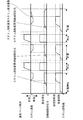
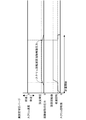
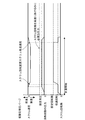
本発明の実施の形態を実施例に基づき図面を参照して説明する。図1〜図5は、本発明の一実施例を示し、図1は射出成形機の射出装置の概要を示す概略説明図、図2は射出成形機の動作における溶融樹脂の流れを示す説明図、図3は通常パージ動作における制御方法を示す流れ図、図4は高設定背圧パージ動作における制御方法を示す流れ図、図5は低設定背圧パージにおける制御方法を示す流れ図である。 Embodiments of the present invention will be described based on examples with reference to the drawings. 1 to 5 show an embodiment of the present invention, FIG. 1 is a schematic explanatory view showing an outline of an injection apparatus of an injection molding machine, and FIG. 2 is an explanatory view showing a flow of molten resin in the operation of the injection molding machine. 3 is a flowchart showing a control method in a normal purge operation, FIG. 4 is a flowchart showing a control method in a high setting back pressure purge operation, and FIG. 5 is a flowchart showing a control method in a low setting back pressure purge.
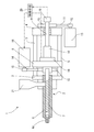
図1において、1は射出成形機の射出装置である。射出成形機は、図示しない成形用金型のキャビティに溶融樹脂を充填するための射出装置1と、フロントプレート3とリヤプレート4との間に連結したタイバー5と、加熱筒6の内部に軸方向に進退自在にかつ周方向に回転自在に挿入されるスクリュ7と、前記スクリュ7の基端部が回転自在に支持されるプッシャープレート8と、前記リヤプレート4に回転自在に支持されたボールねじ軸9と、このボールねじ軸9と螺合するように前記リヤプレート4に固定されたボールナット10と、ベルト11とプーリ12を介して前記ボールねじ軸9を回転させることによって前記スクリュ7を軸方向に進退移動させる射出駆動手段としての射出用サーボモータ13と、ベルト14とプーリ15を介して前記スクリュ7を回転させる回転駆動手段としての計量用サーボモータ16、溶融樹脂の圧力検出手段たるロードセル18と、前記スクリュ7の回転によって前記加熱筒6の先端部に供給される溶融樹脂の圧力により後退する前記スクリュ7の後退速度を検出する後退速度検出手段たるエンコーダ19と、前記計量用サーボモータ16の回転数を制御する制御手段20などから構成されている。
In FIG. 1, 1 is an injection device of an injection molding machine. The injection molding machine includes an
前記制御手段20には、前記ロードセル18により前記加熱筒6の先端側に供給された溶融樹脂の圧力及びエンコーダ19からの前記スクリュ7の後退速度の検出信号が出力され、その溶融樹脂の圧力又はスクリュ7の後退速度の何れか一方の検出値が所定値以下になった条件下では計量用サーボモータ16の回転数を制御して前記スクリュ7を低回転モードに切り換えて運転し、該溶融樹脂の圧力およびスクリュ7の後退速度の何れか一方の検出値が所定値に達した時、スクリュ7を通常回転モードに切り換え制御する。
The control means 20 outputs a detection signal of the pressure of the molten resin supplied to the front end side of the heating cylinder 6 by the
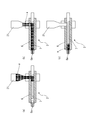
以上のように構成される射出成形機は、原料樹脂を切り替える際あるいは射出成形機の運転を休止する際、加熱筒6内に残っている溶融樹脂を排出するためのパージ動作を行う。このパージ動作におけるスクリュ7の回転制御方法について、図3〜図5を参照して説明する。図3は、通常パージ動作を示しており、まず、パージ動作でのスクリュ7の背圧とスクリュ7の回転速度を設定し、射出成形機によるパージ動作を開始させる。パージ動作を開始すると、予め設定したプログラムに従って前記計量用サーボモータ16を回転させてスクリュ7を回転することによって、加熱筒6の基端部側に設けたホッパ21から加熱筒6内に導入される樹脂材料が溶融、混練されて、加熱筒6の先端部側に供給されて計量される。このパージ動作開始直後においては、ホッパ21から加熱筒6の基端部側に樹脂が供給され、スクリュ7の回転によって加熱筒6の先端側に供給されることから、加熱筒6の先端側に供給された溶融樹脂の圧力は低く、また、スクリュ7は加熱筒6の先端部に供給される溶融樹脂によって後退することもないから、スクリュ7は低回転モードで回転する。そして、徐々に加熱筒6の先端側に溶融樹脂が溜まり、その溶融樹脂の圧力が高まることによって(設定背圧となるように制御されて)、その加熱筒6の先端部に供給される溶融樹脂によって加熱筒6内のスクリュ7がプッシャープレート8と共に後退移動する。この溶融樹脂の圧力をロードセル18で検出するとともに、スクリュ7の後退に伴うボールねじ軸11の回転数をエンコーダ19で検出し、その回転数からスクリュ7の後退速度を演算処理する。この溶融樹脂の圧力が所定値(例えば、0.5MPa)あるいは前記スクリュ7の後退速度が所定値(例えば、5mm/s)に達すると、制御手段20によってスクリュ7を通常回転(設定数の回転数)するよう制御し、それまでの低回転モードから通常回転モードに切り換える。そして、スクリュ7の回転によって加熱筒6の先端側に供給される溶融樹脂によってスクリュ7が後退し、設定された計量完了位置にスクリュ7が到達して溶融樹脂の計量動作が完了すると、スクリュ7の回転を停止する。この後、射出用サーボモータ13によりボールねじ軸9を回転し、ボールナット10、プッシャープレート8を介してスクリュ7を前進させることによって、射出ノズル6aから溶融樹脂を射出する。このようなパージ動作を繰り返した後、ホッパ21からの樹脂の供給が停止すると、スクリュ7の回転による加熱筒6内に溶融樹脂が少なくなるのに伴い(図2(b)から図2(c)の状態に移行)、溶融樹脂の圧力も小さく、また、スクリュ7の後退速度も減少することから、溶融樹脂の圧力とスクリュ7の後退速度を監視し、ロードセル21により検出される溶融樹脂の圧力とスクリュ7の後退速度の何れか一方が所定値以下になった際、加熱筒6内に溶融樹脂が少ないと判断し、スクリュ7は通常回転モードの設定回転速度から低回転モードに切り換えて回転する。これにより、加熱筒6の内壁とスクリュ7との金属接触による損傷を防止することができる。こうして、パージ動作により加熱筒6内の樹脂が排出されると、スクリュ7は自動停止する。
The injection molding machine configured as described above performs a purge operation for discharging the molten resin remaining in the heating cylinder 6 when switching the raw resin or stopping the operation of the injection molding machine. A method for controlling the rotation of the
また、パージ動作後、成形動作を再開する場合、図2の(a)で示すように、パージ動作によって、加熱筒6内に樹脂が無い状態からスクリュ7の回転が開始することになるから、当然、計量開始直後は、加熱筒6の先端側に供給された溶融樹脂の圧力並びにスクリュ7の後退速度も所定値以下である。このため、スクリュ7は低回転モードから開始する。そして、溶融樹脂の圧力とスクリュ7の後退速度の何れか一方が所定値に達した際、加熱筒6内の溶融樹脂が多いと判断し、スクリュ7を低速回転モードから通常回転モードに切り換えることにより、速やかに通常の計量動作へと移行することができる。このように、射出成形機によるパージ動作においては、成形動作からパージ動作を行う場合と、パージ動作から成形動作を行う場合がある。パージ動作においても、図4に示すように、スクリュ7の背圧を高く設定した高設定背圧パージと、図5に示すように、スクリュ7の背圧を低く設定した低設定背圧パージがある。高設定背圧パージにおいて、スクリュ7の背圧を高く設定していると溶融樹脂はノズル先端より垂れ流しの状態となり、スクリュ7は設定背圧にならないために後退することができない。もし、スクリュ7の後退速度のみでスクリュ7の回転数を変更する制御を行った場合は、常に低速回転となってしまう。本発明では、加熱筒6の先端側に供給された溶融樹脂の圧力がある所定値に達すると回転数を変更するためにすみやかに回転数を変更し、パージ動作を行うことができる。低設定背圧パージにおいて、加熱筒6の先端側に供給された溶融樹脂の圧力が低く設定されているために、スクリュ7の回転負荷のみでスクリュ7が後退してしまう。本発明の動作をしなければ、常にスクリュ7が高速で回転するために加熱筒6とスクリュ7が接触する虞がある。スクリュ後退速度をある所定値とすることで加熱筒6内に樹脂がみたされるまでスクリュ7を低速で回転するため、加熱筒とスクリュ7の接触する虞がなくなる。このように、スクリュ7の回転数を切り換える所定値を1つの検出信号(例えばスクリュ7の後退速度のみ)から判断しようとすると、加熱筒6への溶融樹脂の供給量がほとんど無い状態のままスクリュ7が通常回転モードで回転するなど虞れがある。しかしながら、本実施例では、加熱筒6の先端側に供給された溶融樹脂の圧力とスクリュ7の後退速度とを監視し、その溶融樹脂の圧力又はスクリュ7の後退速度の何れか一方が所定値に達するか否かを判断してスクリュ7の回転数を制御するものであるから、溶融樹脂の圧力又は後退速度の検出値に基づいてスクリュ7の回転数を制御できるから、加熱筒6とスクリュ7とが金属接触を起こした状態でスクリュ7が回転を続けることがなく、それらの損傷を未然に防止することができる。また、どのような設定に対してもスクリュ7を通常回転モードへと速やかに移行でき、効率的なパージ動作が可能となる。
Further, when restarting the molding operation after the purge operation, as shown in FIG. 2A, the rotation of the
以上、本発明の一実施例について詳述したが、本発明は、前記実施例に限定されるものではなく、本発明の要旨の範囲内で種々の変形実施例が可能である。 As mentioned above, although one Example of this invention was explained in full detail, this invention is not limited to the said Example, A various deformation | transformation Example is possible within the range of the summary of this invention.
1 射出装置
6 加熱筒
7 スクリュ
13 射出用サーボモータ(射出駆動手段)
16 計量用サーボモータ (射出駆動手段)
18 ロードセル(背圧検出手段)
19 エンコーダ(後退速度検出手段)
20 制御手段
DESCRIPTION OF
16 Servo motor for weighing (Injection drive means)
18 Load cell (back pressure detection means)
19 Encoder (Reverse speed detection means)
20 Control means
Claims (4)
Priority Applications (1)
| Application Number | Priority Date | Filing Date | Title |
|---|---|---|---|
| JP2008005709A JP5255850B2 (en) | 2008-01-15 | 2008-01-15 | Screw rotation control method and screw rotation control device in injection molding machine |
Applications Claiming Priority (1)
| Application Number | Priority Date | Filing Date | Title |
|---|---|---|---|
| JP2008005709A JP5255850B2 (en) | 2008-01-15 | 2008-01-15 | Screw rotation control method and screw rotation control device in injection molding machine |
Publications (2)
| Publication Number | Publication Date |
|---|---|
| JP2009166317A true JP2009166317A (en) | 2009-07-30 |
| JP5255850B2 JP5255850B2 (en) | 2013-08-07 |
Family
ID=40968073
Family Applications (1)
| Application Number | Title | Priority Date | Filing Date |
|---|---|---|---|
| JP2008005709A Active JP5255850B2 (en) | 2008-01-15 | 2008-01-15 | Screw rotation control method and screw rotation control device in injection molding machine |
Country Status (1)
| Country | Link |
|---|---|
| JP (1) | JP5255850B2 (en) |
Cited By (8)
| Publication number | Priority date | Publication date | Assignee | Title |
|---|---|---|---|---|
| JP2011046104A (en) * | 2009-08-27 | 2011-03-10 | Niigata Machine Techno Co Ltd | High shear method using high shear device |
| JP2013154551A (en) * | 2012-01-30 | 2013-08-15 | Japan Steel Works Ltd:The | Flushing method of injection apparatus |
| JP2016002696A (en) * | 2014-06-17 | 2016-01-12 | 株式会社日本製鋼所 | Control method and control apparatus for injection unit |
| CN110039706A (en) * | 2019-04-18 | 2019-07-23 | 东华机械有限公司 | Full-electric injection molding machine and glue melting control method thereof |
| CN113459442A (en) * | 2020-03-31 | 2021-10-01 | 住友重机械工业株式会社 | Injection molding machine |
| CN113829596A (en) * | 2021-09-22 | 2021-12-24 | 珠海格力智能装备有限公司 | Heating control method and device for injection molding machine, storage medium and injection molding machine |
| JP2023069583A (en) * | 2021-11-08 | 2023-05-18 | Ubeマシナリー株式会社 | Weighing control method for injection foam molding |
| JP2023106052A (en) * | 2022-01-20 | 2023-08-01 | Ubeマシナリー株式会社 | Injection device and injection method |
Citations (4)
| Publication number | Priority date | Publication date | Assignee | Title |
|---|---|---|---|---|
| JPH06270213A (en) * | 1993-03-24 | 1994-09-27 | Toyo Mach & Metal Co Ltd | Screw rotation control method |
| JPH10202708A (en) * | 1997-01-21 | 1998-08-04 | Meiki Co Ltd | Resin purging method of hearing cylinder |
| JP2000006207A (en) * | 1998-06-19 | 2000-01-11 | Sumitomo Heavy Ind Ltd | Starting method of rotation of screw in injection molder |
| JP2005014308A (en) * | 2003-06-24 | 2005-01-20 | Niigata Machine Techno Co Ltd | Screw rotation control method in injection molding machine and screw rotation control device |
-
2008
- 2008-01-15 JP JP2008005709A patent/JP5255850B2/en active Active
Patent Citations (4)
| Publication number | Priority date | Publication date | Assignee | Title |
|---|---|---|---|---|
| JPH06270213A (en) * | 1993-03-24 | 1994-09-27 | Toyo Mach & Metal Co Ltd | Screw rotation control method |
| JPH10202708A (en) * | 1997-01-21 | 1998-08-04 | Meiki Co Ltd | Resin purging method of hearing cylinder |
| JP2000006207A (en) * | 1998-06-19 | 2000-01-11 | Sumitomo Heavy Ind Ltd | Starting method of rotation of screw in injection molder |
| JP2005014308A (en) * | 2003-06-24 | 2005-01-20 | Niigata Machine Techno Co Ltd | Screw rotation control method in injection molding machine and screw rotation control device |
Cited By (11)
| Publication number | Priority date | Publication date | Assignee | Title |
|---|---|---|---|---|
| JP2011046104A (en) * | 2009-08-27 | 2011-03-10 | Niigata Machine Techno Co Ltd | High shear method using high shear device |
| JP2013154551A (en) * | 2012-01-30 | 2013-08-15 | Japan Steel Works Ltd:The | Flushing method of injection apparatus |
| JP2016002696A (en) * | 2014-06-17 | 2016-01-12 | 株式会社日本製鋼所 | Control method and control apparatus for injection unit |
| CN110039706A (en) * | 2019-04-18 | 2019-07-23 | 东华机械有限公司 | Full-electric injection molding machine and glue melting control method thereof |
| CN113459442A (en) * | 2020-03-31 | 2021-10-01 | 住友重机械工业株式会社 | Injection molding machine |
| CN113459442B (en) * | 2020-03-31 | 2024-02-06 | 住友重机械工业株式会社 | Injection molding machine |
| CN113829596A (en) * | 2021-09-22 | 2021-12-24 | 珠海格力智能装备有限公司 | Heating control method and device for injection molding machine, storage medium and injection molding machine |
| JP2023069583A (en) * | 2021-11-08 | 2023-05-18 | Ubeマシナリー株式会社 | Weighing control method for injection foam molding |
| JP7793943B2 (en) | 2021-11-08 | 2026-01-06 | Ubeマシナリー株式会社 | Injection foam molding metering control method and injection molding machine |
| JP2023106052A (en) * | 2022-01-20 | 2023-08-01 | Ubeマシナリー株式会社 | Injection device and injection method |
| JP7750114B2 (en) | 2022-01-20 | 2025-10-07 | Ubeマシナリー株式会社 | Injection device and injection method |
Also Published As
| Publication number | Publication date |
|---|---|
| JP5255850B2 (en) | 2013-08-07 |
Similar Documents
| Publication | Publication Date | Title |
|---|---|---|
| JP5255850B2 (en) | Screw rotation control method and screw rotation control device in injection molding machine | |
| US7744787B2 (en) | Anomaly monitoring method of an injection molding machine | |
| JP5657355B2 (en) | Die-casting machine and abnormality detection method for die-casting machine | |
| CN103481479B (en) | The pressure control device of injection moulding machine | |
| JP4027380B2 (en) | Control device for injection molding machine | |
| JP2009000929A (en) | Injection molding machine and abnormality detection method of injection molding machine | |
| JP3851618B2 (en) | Injection molding machine | |
| JP5210785B2 (en) | Injection molding machine | |
| CN112519153B (en) | Control device and control method for injection molding machine | |
| CN112917854B (en) | Control device and control method for injection molding machine | |
| JP6033814B2 (en) | Control method and control apparatus for injection unit | |
| JP7277332B2 (en) | CONTROL DEVICE AND CONTROL METHOD FOR INJECTION MOLDING MACHINE | |
| JP4269802B2 (en) | Screw rotation control method in injection molding machine | |
| US20210178649A1 (en) | Control device and control method for injection molding machine | |
| CN105745057A (en) | Moulding machine | |
| JP4114139B2 (en) | Injection molding machine weighing method | |
| JP2008001028A (en) | Method for detecting abnormality of injection molding machine | |
| JP7356391B2 (en) | Injection molding machine | |
| JP7567521B2 (en) | Screw position setting method and screw type injection device | |
| WO2025057899A1 (en) | Injection molding machine | |
| US20250114990A1 (en) | Injection Molding Machine and Method of Detecting Abnormality of Injection Molding Machine | |
| US20240157618A1 (en) | Control method for injection molding machine and injection molding machine | |
| JP3575519B2 (en) | Injection molding machine and its injection control method | |
| JP2025062310A (en) | Method and device for controlling an injection molding machine | |
| JP5226191B2 (en) | Molding machine and control method thereof |
Legal Events
| Date | Code | Title | Description |
|---|---|---|---|
| A621 | Written request for application examination |
Free format text: JAPANESE INTERMEDIATE CODE: A621 Effective date: 20101006 |
|
| A521 | Request for written amendment filed |
Free format text: JAPANESE INTERMEDIATE CODE: A523 Effective date: 20110929 |
|
| A977 | Report on retrieval |
Free format text: JAPANESE INTERMEDIATE CODE: A971007 Effective date: 20120914 |
|
| A131 | Notification of reasons for refusal |
Free format text: JAPANESE INTERMEDIATE CODE: A131 Effective date: 20120925 |
|
| A521 | Request for written amendment filed |
Free format text: JAPANESE INTERMEDIATE CODE: A523 Effective date: 20121120 |
|
| TRDD | Decision of grant or rejection written | ||
| A01 | Written decision to grant a patent or to grant a registration (utility model) |
Free format text: JAPANESE INTERMEDIATE CODE: A01 Effective date: 20130416 |
|
| A61 | First payment of annual fees (during grant procedure) |
Free format text: JAPANESE INTERMEDIATE CODE: A61 Effective date: 20130422 |
|
| R150 | Certificate of patent or registration of utility model |
Ref document number: 5255850 Country of ref document: JP Free format text: JAPANESE INTERMEDIATE CODE: R150 Free format text: JAPANESE INTERMEDIATE CODE: R150 |
|
| FPAY | Renewal fee payment (event date is renewal date of database) |
Free format text: PAYMENT UNTIL: 20160426 Year of fee payment: 3 |
|
| R250 | Receipt of annual fees |
Free format text: JAPANESE INTERMEDIATE CODE: R250 |