JP2009166315A - Liquid ejector and image forming apparatus - Google Patents

Liquid ejector and image forming apparatus Download PDF

Info

Publication number
JP2009166315A
JP2009166315A JP2008005650A JP2008005650A JP2009166315A JP 2009166315 A JP2009166315 A JP 2009166315A JP 2008005650 A JP2008005650 A JP 2008005650A JP 2008005650 A JP2008005650 A JP 2008005650A JP 2009166315 A JP2009166315 A JP 2009166315A
Authority
JP
Japan
Prior art keywords
unit
maintenance
head
head unit
liquid
Prior art date
Legal status (The legal status is an assumption and is not a legal conclusion. Google has not performed a legal analysis and makes no representation as to the accuracy of the status listed.)
Pending
Application number
JP2008005650A
Other languages
Japanese (ja)
Inventor
Yusuke Nemoto
雄介 根本
Current Assignee (The listed assignees may be inaccurate. Google has not performed a legal analysis and makes no representation or warranty as to the accuracy of the list.)
Ricoh Co Ltd
Original Assignee
Ricoh Co Ltd
Priority date (The priority date is an assumption and is not a legal conclusion. Google has not performed a legal analysis and makes no representation as to the accuracy of the date listed.)
Filing date
Publication date
Application filed by Ricoh Co Ltd filed Critical Ricoh Co Ltd
Priority to JP2008005650A priority Critical patent/JP2009166315A/en
Publication of JP2009166315A publication Critical patent/JP2009166315A/en
Pending legal-status Critical Current

Links

Images

Abstract

<P>PROBLEM TO BE SOLVED: To provide a liquid ejector which can simultaneously carry out by a simple constitution alignment in a main scan direction between a plurality of liquid ejecting heads and corresponding caps when the maintenance/recovery action for the liquid ejecting heads is carried out, and to provide an image forming apparatus equipped with this. <P>SOLUTION: In the ink ejector (liquid ejector) 1, when a head unit 11 moves towards a maintenance/recovery unit 13, pins (parts to be guided) 19a and 19b engage with guide grooves (guiding parts) 33a and 33b, thereby performing alignment between the head unit 11 and the maintenance/recovery unit 13 in a direction orthogonal to a movement direction of the head unit 11. A driving control part 22 decreases a movement speed of the head unit 11 before the pins 19a, 19b and the guide grooves 33a, 33b start the engagement with each other. <P>COPYRIGHT: (C)2009,JPO&INPIT

Description

本発明は記録媒体に液体を吐出する液体吐出装置、及びこの液体吐出装置を備え記録媒体に画像を形成する画像形成装置に関する。   The present invention relates to a liquid ejecting apparatus that ejects liquid onto a recording medium, and an image forming apparatus that includes the liquid ejecting apparatus and forms an image on a recording medium.

図12に示す従来技術Aにおいては、液体吐出ヘッド101の維持・回復のためのキャッピング動作を行うときに、液体吐出ヘッド101とキャップ103との主走査方向におけるずれWの修正を、主走査方向の位置合わせ用のキャップガイド105によってキャップ103を液体吐出ヘッド101に正対する位置に案内することにより行っていた。   In the related art A shown in FIG. 12, when the capping operation for maintaining and recovering the liquid ejection head 101 is performed, the correction of the shift W between the liquid ejection head 101 and the cap 103 in the main scanning direction is corrected. In this case, the cap 103 is guided to a position facing the liquid discharge head 101 by the cap guide 105 for positioning.

特開2005−137075号公報JP 2005-137075 A

しかしながら、従来技術Aにおいては、液体吐出ヘッド101が複数ある場合に、ヘッド101毎にキャップガイド105を設けなければならず構成が複雑であった。   However, in the related art A, when there are a plurality of liquid ejection heads 101, the cap guide 105 must be provided for each head 101, and the configuration is complicated.

そこで、本発明は、液体吐出ヘッドの維持・回復動作を行うときに、複数の液体吐出ヘッドと対応するキャップとの主走査方向の位置合わせを、簡易な構成で同時に行うことができる液体吐出装置及びこれを備えた画像形成装置の提供を目的とする。   Accordingly, the present invention provides a liquid ejection apparatus capable of simultaneously performing alignment of a plurality of liquid ejection heads and corresponding caps in the main scanning direction with a simple configuration when performing a maintenance / recovery operation of the liquid ejection heads. An object of the present invention is to provide an image forming apparatus including the same.

前記課題を解決するために、請求項1に記載された発明は、液体吐出ヘッドを有するヘッドユニットと、液体吐出ヘッドの維持・回復ユニットと、ヘッドユニットを記録位置と維持・回復ユニットに対向する位置との間で移動させる駆動部と、ヘッドユニットの駆動を制御する駆動制御部とを備え、液体吐出ヘッドは記録媒体に液体を吐出して画像を記録するものであり、ヘッドユニットと維持・回復ユニットの何れか一方にはヘッドユニットの移動方向に沿ったガイド部が設けられており他方にはガイド部と係合する被ガイド部が設けられており、ヘッドユニットが維持・回復ユニットに向けて移動したときに、被ガイド部はガイド部と係合してヘッドユニットと維持・回復ユニットとにおけるヘッドユニットの移動方向に直交する方向の位置合わせをするものであり、駆動制御部は、ガイド部と被ガイド部とが係合を開始する前にヘッドユニットの移動速度を低くすることを特徴とする。   In order to solve the above problems, the invention described in claim 1 is directed to a head unit having a liquid discharge head, a liquid discharge head maintenance / recovery unit, and a head unit facing a recording position and a maintenance / recovery unit. And a drive control unit that controls the drive of the head unit, and the liquid discharge head records an image by discharging liquid onto a recording medium. One of the recovery units is provided with a guide portion along the moving direction of the head unit, and the other is provided with a guided portion that engages with the guide portion so that the head unit faces the maintenance / recovery unit. The guided portion engages with the guide portion and moves in a direction perpendicular to the moving direction of the head unit between the head unit and the maintenance / recovery unit. It is intended to the location registration, the drive control section, and a guide portion and the guide portion, characterized in that to lower the moving speed of the head unit before starting the engagement.

請求項2に記載された発明は、請求項1に記載の発明において、ガイド部は維持・回復ユニットに形成された溝であり、ガイド部の記録位置側の端部は記録位置側程広がるテーパー形状となっており、被ガイド部の径はテーパーの最小径以下であることを特徴とする。   According to a second aspect of the present invention, in the first aspect of the present invention, the guide portion is a groove formed in the maintenance / recovery unit, and the end portion of the guide portion on the recording position side is tapered toward the recording position side. It has a shape, and the diameter of the guided portion is less than the minimum diameter of the taper.

請求項3に記載された発明は、請求項1に記載の発明において、ガイド部はヘッドユニットの移動方向に直交する方向の両側に設けられていることを特徴とする。   The invention described in claim 3 is characterized in that, in the invention described in claim 1, the guide portions are provided on both sides in a direction orthogonal to the moving direction of the head unit.

請求項4に記載された発明は、請求項1〜3の何れか一項に記載の発明において、維持・回復ユニットは、液体吐出ヘッドをキャッピングするキャッピング部と、キャッピング部を支持する支持部とを備え、キャッピング部と支持部の何れか一方にはヘッドユニットの移動方向に直交する方向に長孔が形成されており他方には長孔に係合する突起が形成されていることを特徴とする。   According to a fourth aspect of the present invention, in the invention according to any one of the first to third aspects, the maintenance / recovery unit includes a capping unit for capping the liquid discharge head, and a support unit for supporting the capping unit. And a long hole is formed in one of the capping part and the support part in a direction perpendicular to the moving direction of the head unit, and a protrusion engaging with the long hole is formed in the other. To do.

請求項5に記載された発明は、請求項1〜4の何れか一項に記載の液体吐出装置を備え、記録媒体に液体を吐出して画像を形成することを特徴とする画像形成装置である。   According to a fifth aspect of the present invention, there is provided an image forming apparatus comprising the liquid ejecting apparatus according to any one of the first to fourth aspects, wherein the liquid is ejected onto a recording medium to form an image. is there.

本発明によれば、ヘッドユニットと維持・回復ユニットの何れか一方にガイド部を設けて且つ他方にガイド部に係合する被ガイド部を設けただけの簡易な構成で、複数の液体吐出ヘッドと対応するキャップとの主走査方向の位置合わせを同時に行うことができる。   According to the present invention, a plurality of liquid ejection heads with a simple configuration in which a guide portion is provided on one of the head unit and the maintenance / recovery unit and a guided portion that engages with the guide portion is provided on the other. And the corresponding cap can be simultaneously aligned in the main scanning direction.

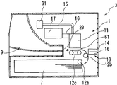
以下、添付図面の図1〜図8を参照して、本発明の実施の形態を説明する。本実施の形態に係るインク吐出装置(液体吐出装置)1は、図8に示すように、画像形成装置3に搭載されている。画像形成装置3は、インク吐出方式により画像を形成するプリンターであり、記録媒体(用紙)にインクを吐出して画像を記録するインク吐出装置1と、記録媒体をセットする給紙トレイ7と、給紙トレイ7から記録媒体を送り出す給紙ローラ12аと、記録媒体を記録領域14に搬送する搬送ローラ12bと、記録領域14において記録媒体を搬送する搬送ベルト12cと、記録領域14で画像を記録された記録媒体を排出する排紙トレイ9とを備えている。   Hereinafter, embodiments of the present invention will be described with reference to FIGS. An ink discharge apparatus (liquid discharge apparatus) 1 according to the present embodiment is mounted on an image forming apparatus 3 as shown in FIG. The image forming apparatus 3 is a printer that forms an image by an ink ejection method, and an ink ejection apparatus 1 that ejects ink onto a recording medium (paper) to record an image; a paper feed tray 7 that sets the recording medium; An image is recorded in the recording area 14 by a sheet feeding roller 12a for feeding the recording medium from the sheet feeding tray 7, a conveying roller 12b for conveying the recording medium to the recording area 14, a conveying belt 12c for conveying the recording medium in the recording area 14, and the recording area 14. And a paper discharge tray 9 for discharging the recorded recording medium.

液体吐出装置1は、図8に示すように、複数のインク吐出ヘッド5(図1(a)参照)を有するヘッドユニット11と、インク吐出ヘッド5の維持・回復動作を行う維持・回復ユニット13と、ヘッドユニット11を主走査方向に直交する方向に移動させる駆動部21(図6参照)と、駆動部21を制御する駆動制御部22(図6参照)と、インク吐出ヘッド5に供給するインクを貯留するインクタンク31と、インクタンク31からインク吐出ヘッド5にインクを供給するインクチューブ15とを備えている。   As shown in FIG. 8, the liquid ejection apparatus 1 includes a head unit 11 having a plurality of ink ejection heads 5 (see FIG. 1A) and a maintenance / recovery unit 13 that performs a maintenance / recovery operation of the ink ejection heads 5. And a drive unit 21 (see FIG. 6) that moves the head unit 11 in a direction orthogonal to the main scanning direction, a drive control unit 22 (see FIG. 6) that controls the drive unit 21, and the ink ejection head 5 An ink tank 31 that stores ink and an ink tube 15 that supplies ink from the ink tank 31 to the ink discharge head 5 are provided.

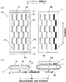
ヘッドユニット11は、図1(a)に示すように、記録媒体の幅分のインク吐出ヘッド5を用いたライン型のヘッドユニットである。ライン型のヘッドユニットは、記録媒体を間欠駆動無しに搬送、印字可能であり、印字の高速化が図れる。   As shown in FIG. 1A, the head unit 11 is a line type head unit using an ink discharge head 5 corresponding to the width of the recording medium. The line-type head unit can convey and print a recording medium without intermittent driving, and can increase the printing speed.

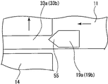
ヘッドユニット11には、図1(a)に示すように、液滴を吐出するノズルを主走査方向に配列したインク吐出ヘッド5が千鳥状に配置されており、ヘッドユニット11の長手方向の両端側(ヘッドユニットの移動方向に直交する方向の両側)には、図1(a)、(b)に示すように、下側に突出した円柱状のピン(被ガイド部)19а、19bが設けられている。   In the head unit 11, as shown in FIG. 1A, ink discharge heads 5 in which nozzles for discharging droplets are arranged in the main scanning direction are arranged in a staggered manner, and both ends of the head unit 11 in the longitudinal direction are arranged. As shown in FIGS. 1A and 1B, cylindrical pins (guided portions) 19a and 19b projecting downward are provided on the side (both sides perpendicular to the moving direction of the head unit). It has been.

インク吐出ヘッド5は、図8に示すように、インクタンク31に、インクチューブ15により接続されており、インクタンク31からインクの供給を受けている。また、インク吐出ヘッド11は電源ボックス17にフレキシブルケーブル(インクヘッド制御ケーブル)16により接続されており、電源ボックス17からインク吐出ヘッド11や搬送ベルト12c等の駆動モータに駆動電源及び駆動制御信号を送信してこれらの駆動を制御している。   As shown in FIG. 8, the ink discharge head 5 is connected to the ink tank 31 by the ink tube 15 and receives ink supplied from the ink tank 31. The ink discharge head 11 is connected to a power supply box 17 by a flexible cable (ink head control cable) 16, and a drive power supply and a drive control signal are supplied from the power supply box 17 to drive motors such as the ink discharge head 11 and the transport belt 12 c. These are controlled by transmitting.

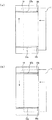
維持・回復ユニット13は、複数のインク吐出ヘッド5を同時にキャッピングするキャッピング部14と、キャッピング部14を支持する支持部16とを備えている。キャッピング部14の下面には主走査方向に沿った長孔25が4つ形成されており、支持部16の上面には各長孔25に入り込んだ突起27が形成されている。即ち、キャッピング部14は、支持部16上を主走査方向に沿ってスライドして、長孔25の長さの分だけ移動するようになっている。尚、各突起27の径は、各長孔25の幅と同程度である。   The maintenance / recovery unit 13 includes a capping unit 14 for capping a plurality of ink ejection heads 5 at the same time, and a support unit 16 for supporting the capping unit 14. Four long holes 25 along the main scanning direction are formed on the lower surface of the capping portion 14, and protrusions 27 that enter the respective long holes 25 are formed on the upper surface of the support portion 16. In other words, the capping unit 14 slides on the support unit 16 along the main scanning direction and moves by the length of the long hole 25. The diameter of each projection 27 is approximately the same as the width of each long hole 25.

キャッピング部14には、図1(a)に示すように、各インク吐出ヘッド5をキャッピングするキャップ35が千鳥状に配列されており、キャッピング部14の長手方向の両端側(ヘッドユニットの移動方向に直交する方向の両側)には、ヘッドユニット11の移動方向に沿った案内溝(ガイド部)33а、33bが形成されている。   As shown in FIG. 1A, caps 35 for capping the respective ink discharge heads 5 are arranged in a staggered manner in the capping unit 14, and both end sides in the longitudinal direction of the capping unit 14 (the moving direction of the head unit). Guide grooves (guide portions) 33a and 33b along the moving direction of the head unit 11 are formed on both sides in a direction orthogonal to the head.

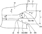
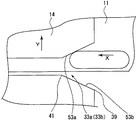
案内溝33а、33bの開口部は上側に向いており、案内溝33а、33bの一端部は図3に示すように、キャッピング部14の一側面37а側が広がったハ字状(テーパ形状)となっている。   The opening portions of the guide grooves 33a and 33b are directed upward, and one end portions of the guide grooves 33a and 33b are formed in a C shape (taper shape) in which one side surface 37a side of the capping portion 14 is widened as shown in FIG. ing.

案内溝33а、33bの一端は、図3に示すように、ハ字の最大幅部39であり、開放されている。各案内溝33а、33bの最大幅部39の幅T(図3参照)は、各長孔25の長さと同程度である。   As shown in FIG. 3, one end of each of the guide grooves 33a and 33b is a C-shaped maximum width portion 39 and is open. The width T (see FIG. 3) of the maximum width portion 39 of each guide groove 33a, 33b is approximately the same as the length of each long hole 25.

案内溝33а、33bは、図1(a)に示すように、ハ字の最小幅部41から同じ幅(テーパーの最小径)G(図3参照)でキャッピング部14の他側面37bまでヘッドユニット11の移動方向(主走査方向に直交する方向)に沿って連続している。ピン19а、19bの径Pは、図3に示すように、最小幅部41の幅Gよりも僅かに小さい(テーパーの最小径以下)である。即ち、ヘッドユニット11が維持・回復ユニット13側に移動して、ピン19а、19bが最小幅部41よりも内側に入り込むと、インク吐出ヘッド5とキャップ35との主走査方向の位置合わせがなされるようになっている。   As shown in FIG. 1 (a), the guide grooves 33a, 33b are head units extending from the C-shaped minimum width portion 41 to the other side surface 37b of the capping portion 14 with the same width (minimum taper diameter) G (see FIG. 3). 11 moving directions (directions orthogonal to the main scanning direction). As shown in FIG. 3, the diameters P of the pins 19a and 19b are slightly smaller than the width G of the minimum width portion 41 (less than the minimum diameter of the taper). That is, when the head unit 11 moves to the maintenance / recovery unit 13 side and the pins 19a, 19b enter inside the minimum width portion 41, the ink discharge head 5 and the cap 35 are aligned in the main scanning direction. It has become so.

案内溝33а、33bにピン19а、19bが入り込んだときのピン19а、19bの先端から案内溝33а、33bの底壁までの距離は、正対するインク吐出ヘッド5の先端とキャップ35の先端との距離よりも長い。即ち、ピン19а、19bの長さ及び案内溝33а、33bの深さは、維持・回復ユニット13が上昇してインク吐出ヘッド5をキャッピングすることを妨げない長さ及び深さとなっている。   The distance from the tip of the pin 19a, 19b to the bottom wall of the guide groove 33a, 33b when the pin 19a, 19b enters the guide groove 33a, 33b is the distance between the tip of the ink discharge head 5 and the tip of the cap 35 facing each other. Longer than the distance. That is, the lengths of the pins 19a and 19b and the depths of the guide grooves 33a and 33b are the lengths and depths that do not prevent the maintenance / recovery unit 13 from rising and capping the ink discharge head 5.

キャップ35は、インク吐出ヘッド5の維持・回復動作のときに、インク吐出ヘッド5をキャッピングするものである。インク吐出ヘッド5は、キャッピング中に、不使用ノズルの乾燥防止手段としての予備吐出を行い、また、所定の印字数量を実施後にポンプにより吸引が行われる。各キャップ35は、ヘッドユニット11と維持・回復ユニット13の位置合わせが成されると、各インク吐出ヘッド5に正対するように、維持・回復ユニット13に配置されている。   The cap 35 caps the ink discharge head 5 when the ink discharge head 5 is maintained and recovered. The ink ejection head 5 performs preliminary ejection as a means for preventing drying of unused nozzles during capping, and suction is performed by a pump after a predetermined number of prints. Each cap 35 is arranged in the maintenance / recovery unit 13 so as to face each ink ejection head 5 when the head unit 11 and the maintenance / recovery unit 13 are aligned.

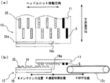
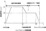
駆動部21は、モータの駆動力で、ヘッドユニット11を印字位置(記録位置)Rとインク吐出ヘッド5の維持・回復動作を行うメンテナンス位置M(図4参照)との間を移動させるものである。尚、画像形成装置3には、図6に示すように、ヘッドユニット11の移動速度Vを計測する速度検知器43と、ヘッドユニット11を検知する第1センサ45及び第2センサ47が設けられている。第1センサ45はヘッドユニット11の移動距離がL1(図5参照)になったとき(ヘッドユニット11が印字位置Rから速度制限位置Kに移動したとき(図2参照))に検知し、第2センサ47はヘッドユニット11の移動距離がL2(図5参照)になったときに検知するように配置されている。   The drive unit 21 moves the head unit 11 between a printing position (recording position) R and a maintenance position M (see FIG. 4) where the ink discharge head 5 is maintained / recovered by the driving force of the motor. is there. As shown in FIG. 6, the image forming apparatus 3 is provided with a speed detector 43 that measures the moving speed V of the head unit 11, and a first sensor 45 and a second sensor 47 that detect the head unit 11. ing. The first sensor 45 detects when the moving distance of the head unit 11 becomes L1 (see FIG. 5) (when the head unit 11 moves from the printing position R to the speed limit position K (see FIG. 2)). The two sensors 47 are arranged so as to detect when the moving distance of the head unit 11 becomes L2 (see FIG. 5).

駆動制御部22は、図6に示すように、駆動部21のモータの回転速度を制御することによりヘッドユニット11の移動速度Vを制御するものであり、速度検知器43が計測した速度と通常速度V1及び衝撃緩和速度V2とを比較する比較部49と、第1センサ45及び第2センサ47からの検知信号を受信する受信部51とを備えている。尚、図5に示すように、本実施の形態では、衝撃緩和速度V2は通常速度V1の60%程度である。   As shown in FIG. 6, the drive control unit 22 controls the moving speed V of the head unit 11 by controlling the rotation speed of the motor of the drive unit 21, and the speed measured by the speed detector 43 and the normal speed. The comparison part 49 which compares the speed V1 and the impact relaxation speed V2, and the receiving part 51 which receives the detection signal from the 1st sensor 45 and the 2nd sensor 47 are provided. As shown in FIG. 5, in the present embodiment, the impact relaxation speed V2 is about 60% of the normal speed V1.

次に、本実施の形態に係る画像形成装置3の動作を説明する。パソコン等からの印刷開始信号を受信すると、給紙トレイ7にセットされた記録媒体が給紙ローラ12аにより送り出され、搬送ローラ12bにより記録領域61に搬送される。記録領域61に搬送された記録媒体は搬送ベルト12cにより搬送されつつインク吐出装置1からインクの吐出を受ける。インクの吐出を受けた記録媒体は、開口部23を通過して、排紙トレイ9に排出される。   Next, the operation of the image forming apparatus 3 according to the present embodiment will be described. When a print start signal is received from a personal computer or the like, the recording medium set in the paper feed tray 7 is sent out by the paper feed roller 12a and conveyed to the recording area 61 by the conveyance roller 12b. The recording medium conveyed to the recording area 61 receives ink ejection from the ink ejection device 1 while being conveyed by the conveyance belt 12c. The recording medium that has received the ink discharge passes through the opening 23 and is discharged to the paper discharge tray 9.

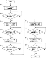
インク吐出装置1は、印字の合間に、インク吐出ヘッド5の維持・回復動作を行う。記録動作を行ってから維持・回復動作に移行するまでの一連の流れについて、図5のグラフ及び図7のフローチャートを用いて説明する。   The ink ejection apparatus 1 performs the maintenance / recovery operation of the ink ejection head 5 between printing. A series of flow from the recording operation to the maintenance / recovery operation will be described with reference to the graph of FIG. 5 and the flowchart of FIG.

先ず、駆動部21のモータを駆動して、ヘッドユニット11の維持・回復ユニット13側への移動を開始する(S1)。ヘッドユニット11の速度が通常速度V1になったら、速度を一定にする(S2)。ヘッドユニット11の移動距離がL1になったら(S4)、ヘッドユニット11の速度を下げる(S5)。速度が衝撃緩和速度V2になったら(S6)、速度を一定にする(S7)。   First, the motor of the drive unit 21 is driven to start the movement of the head unit 11 toward the maintenance / recovery unit 13 (S1). When the speed of the head unit 11 reaches the normal speed V1, the speed is made constant (S2). When the moving distance of the head unit 11 becomes L1 (S4), the speed of the head unit 11 is reduced (S5). When the speed reaches the impact relaxation speed V2 (S6), the speed is made constant (S7).

ヘッドユニット11は、衝撃緩和速度V2のまま、維持・回復ユニット13に対向する位置に移動する。このとき、図3に示すように、各ピン19а、19bが各案内溝33а、33bの一方の側壁53аに衝突した場合には、各ピン19а、19bは側壁53аと当接しつつ図3のX方向(主走査方向に直交する方向)に進んで、最小幅部41に到達する。一方、キャッピング部14は、各ピン19а、19bに押圧されて、図3のY方向(主走査方向に沿った方向)に移動する。このようにして、ヘッドユニット11とキャッピング部14との主走査方向の位置合わせがなされる。   The head unit 11 moves to a position facing the maintenance / recovery unit 13 while maintaining the impact relaxation speed V2. At this time, as shown in FIG. 3, when each pin 19a, 19b collides with one side wall 53a of each guide groove 33a, 33b, each pin 19a, 19b is in contact with the side wall 53a while the X in FIG. Advancing in the direction (a direction perpendicular to the main scanning direction) and reaching the minimum width portion 41. On the other hand, the capping unit 14 is pressed by the pins 19a and 19b and moves in the Y direction (direction along the main scanning direction) in FIG. In this way, the head unit 11 and the capping unit 14 are aligned in the main scanning direction.

ピン19а、19bが他方の側壁53bに衝突した場合には、各ピン19а、19bは側壁53bと当接しつつ図3のX方向(主走査方向に直交する方向)に進んで、最小幅部41に到達する。一方、キャッピング部14は、各ピン19а、19bに押圧されて、図3のY方向と反対方向に移動する。尚、一方及び他方の側壁53а、53bは、図3に示すように、ハ字を成している。   When the pins 19a and 19b collide with the other side wall 53b, each pin 19a and 19b advances in the X direction (direction perpendicular to the main scanning direction) in FIG. To reach. On the other hand, the capping portion 14 is pressed by the pins 19a, 19b and moves in the direction opposite to the Y direction in FIG. In addition, the one and other side walls 53a and 53b form a letter C as shown in FIG.

ヘッドユニット11の移動距離がL2になったら(S8)、速度を下げて(S9)、速度が0になったら(S10)、ヘッドユニット11はメンテナンス位置M(図4参照)に停止する(フロー終了)。   When the moving distance of the head unit 11 becomes L2 (S8), the speed is lowered (S9), and when the speed becomes 0 (S10), the head unit 11 stops at the maintenance position M (see FIG. 4) (flow). End).

このとき、各インク吐出ヘッド5と各キャップ35が正対しているので、維持・回復ユニット13を上昇させて、各インク吐出ヘッド5を確実にキャッピングすることができる。   At this time, since each ink discharge head 5 and each cap 35 face each other, the maintenance / recovery unit 13 can be raised to reliably cap each ink discharge head 5.

尚、ヘッドユニット11は、メンテナンス位置Mで維持・回復動作を行った後、通常速度V1で印字位置Rに移動して、印字を再開する。   The head unit 11 performs the maintenance / recovery operation at the maintenance position M, and then moves to the printing position R at the normal speed V1 to resume printing.

次に、本実施の形態に係るインク吐出装置1の作用効果を説明する。   Next, the function and effect of the ink ejection apparatus 1 according to the present embodiment will be described.

本実施の形態に係るインク吐出装置1によれば、ヘッドユニット11と維持・回復ユニット13の何れか一方に案内溝(ガイド部)33а、33bを形成し且つ他方に案内溝33а、33bに入り込む(係合する)ピン(被ガイド部)19а、19bを設けただけの簡易な構成で、複数の液体吐出ヘッド11と対応するキャップ35との主走査方向の位置合わせを同時に行うことができる。   According to the ink ejection apparatus 1 according to the present embodiment, the guide grooves (guide portions) 33a and 33b are formed in one of the head unit 11 and the maintenance / recovery unit 13, and the guide grooves 33a and 33b enter the other. With a simple configuration in which the (engaging) pins (guided portions) 19a and 19b are simply provided, it is possible to simultaneously align the plurality of liquid ejection heads 11 and the corresponding caps 35 in the main scanning direction.

案内溝33а、33bとピン19а、19bとが係合を開始する前に、ヘッドユニット11の移動速度Vを通常速度V1よりも低い衝撃緩和速度V2に設定するので、ピン19а、19bと案内溝33а、33bの側壁53а、53bとが衝突(係合を開始)するときの衝撃を緩和することができる。   Before the guide grooves 33a, 33b and the pins 19a, 19b start to be engaged, the moving speed V of the head unit 11 is set to an impact relaxation speed V2 lower than the normal speed V1, so the pins 19a, 19b and the guide grooves The impact when the side walls 53a and 53b of the 33a and 33b collide (begin engagement) can be reduced.

維持・回復ユニット13のキャッピング部14が長孔(ガイド)25の長さ方向に(主走査方向に沿って)移動自在なので、キャッピング部14をヘッドユニット11に追従させることができる。従って、複数の液体吐出ヘッド11と対応するキャップ35との主走査方向の位置合わせを、簡易な構成で、スムーズ且つ確実に行うことができる。   Since the capping portion 14 of the maintenance / recovery unit 13 is movable in the length direction of the long hole (guide) 25 (along the main scanning direction), the capping portion 14 can follow the head unit 11. Therefore, alignment of the plurality of liquid ejection heads 11 and the corresponding caps 35 in the main scanning direction can be performed smoothly and reliably with a simple configuration.

ピン19а、19bの横断面が円弧状なので、案内溝33а、33bの側壁53а、53bとの係合をスムーズに開始することができる。   Since the cross sections of the pins 19a and 19b are arcuate, the engagement with the side walls 53a and 53b of the guide grooves 33a and 33b can be started smoothly.

上述の効果を奏する液体吐出装置1を備え、記録媒体に画像を記録する画像形成装置3を提供できる。   It is possible to provide an image forming apparatus 3 that includes the liquid ejection apparatus 1 that exhibits the above-described effects and that records an image on a recording medium.

本発明は、上述した実施の形態に限定されること無く、その要旨を逸脱しない範囲で種々変形可能である。   The present invention is not limited to the above-described embodiment, and various modifications can be made without departing from the scope of the invention.

上述の実施の形態では、インク吐出装置1を画像形成装置3に搭載しているが、これに代えて、液晶吐出装置を画像形成装置に搭載しても良く、上述した効果と同様な効果が得られる。   In the above-described embodiment, the ink discharge apparatus 1 is mounted on the image forming apparatus 3. However, instead of this, a liquid crystal discharge apparatus may be mounted on the image forming apparatus. can get.

上述の実施の形態では、インク吐出装置1をプリンターに搭載しているが、これに限らず、インク吐出装置1を複写機等に設けても良い。   In the above-described embodiment, the ink discharge device 1 is mounted on the printer. However, the present invention is not limited to this, and the ink discharge device 1 may be provided in a copying machine or the like.

上述の実施の形態では、ヘッドユニット11にピン19а、19bを設けて且つ維持・回復ユニット13に案内溝33а、33bを形成しているが、これに代えて、ヘッドユニットに案内溝33а、33bを形成して且つ維持・回復ユニットにピン19а、19bを設けても良い。   In the above-described embodiment, the pins 19a and 19b are provided in the head unit 11 and the guide grooves 33a and 33b are formed in the maintenance / recovery unit 13. Instead, the guide grooves 33a and 33b are provided in the head unit. And the pins 19a and 19b may be provided in the maintenance / recovery unit.

上述の実施の形態では、キャッピング部14に長孔25を形成して且つ支持部16に突起27を形成して突起27が長孔25に入り込むようにしているが、これに代えて、キャッピング部14に突起27を形成して且つ支持部16に長孔25を形成して突起27が長孔25に入り込むようにしても良い。   In the above-described embodiment, the long hole 25 is formed in the capping portion 14 and the protrusion 27 is formed in the support portion 16 so that the protrusion 27 enters the long hole 25. Instead, the capping portion 14 may be formed, and the long hole 25 may be formed in the support portion 16 so that the protrusion 27 enters the long hole 25.

上述の実施の形態では、ヘッドユニット11にピンを2つ設けて且つ維持・回復ユニット13に案内溝を2つ形成しているが、これに限らず、例えば、ヘッドユニット11に1つのピン19аを設けて且つ維持・回復ユニット13に1つの案内溝33аを設けても良い。この場合、図9に示すようにピン19аをヘッドユニット11の移動方向に沿って長い形状とするか、又は、ピン19аをヘッドユニット11の移動方向に沿って複数並べて設けると良い。   In the above embodiment, the head unit 11 has two pins and the maintenance / recovery unit 13 has two guide grooves. However, the present invention is not limited to this. And one guide groove 33a may be provided in the maintenance / recovery unit 13. In this case, as shown in FIG. 9, the pins 19 a may have a long shape along the movement direction of the head unit 11, or a plurality of pins 19 a may be provided side by side along the movement direction of the head unit 11.

上述の実施の形態では、維持・回復ユニット13に案内溝33а、33bを形成しているが、これに代えて、維持・回復ユニット13に2つの直線状のレールを案内溝33а、33bの幅Gだけ離間した位置に設けて、ピンがレール同士の間を移動するようにしても良い。   In the embodiment described above, the guide / grooves 33a and 33b are formed in the maintenance / recovery unit 13, but instead of this, two linear rails are provided in the maintenance / recovery unit 13 in the width of the guide grooves 33a and 33b. It may be provided at a position separated by G so that the pin moves between the rails.

上述の実施の形態では、案内溝33а、33bの一端部をハ字状とし、ピン19а、19bの横断面を円弧状としているが、これに代えて、図10に示すように、案内溝33а、33bの幅を均一にして且つピン19а、19bの側部55の横断面を維持・回復ユニット13側に突出した三角形状としても良い。   In the above-described embodiment, one end of the guide grooves 33a and 33b is formed in a letter C shape, and the cross section of the pins 19a and 19b is formed in an arc shape. Instead, as shown in FIG. , 33b may have a uniform width, and the cross section of the side portion 55 of the pins 19a, 19b may have a triangular shape protruding toward the maintenance / recovery unit 13.

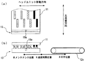
上述の実施の形態では、維持・回復ユニット13に案内溝(ガイド部)33а、33bを形成しているが、これに代えて、図11(a)及び(b)に示すように、維持・回復ユニット13に上側に突出するレール(ガイド部)57а、57bを主走査方向に沿った両端側に1つずつ設けても良い。尚、図11(a)及び(b)では、各レール57а、57bの一端部は印字位置R側程狭くなるテーパー形状となっている。   In the above-described embodiment, the guide / grooves (guide portions) 33a and 33b are formed in the maintenance / recovery unit 13, but instead of this, as shown in FIGS. Rails (guide portions) 57a and 57b protruding upward from the recovery unit 13 may be provided one by one on both end sides along the main scanning direction. In FIGS. 11A and 11B, one end of each rail 57a, 57b has a tapered shape that becomes narrower toward the print position R side.

上述の実施の形態では、維持・回復ユニット13に長孔25を設けているが、これに代えて、維持・回復ユニット13に2つの直線状のレールを長孔25の幅だけ離間した位置に設けて、支持部16の突起27がレール同士の間に入り込むようにしても良い。   In the above-described embodiment, the long hole 25 is provided in the maintenance / recovery unit 13, but instead, two linear rails are separated from the maintenance / recovery unit 13 by the width of the long hole 25. It may be provided so that the protrusion 27 of the support portion 16 enters between the rails.

上述の実施の形態では、衝撃緩和速度V2を通常速度V1の60%程度としているが、これに限らず、例えば、衝撃緩和速度V2を通常速度V1の40%程度としてもよい。   In the above-described embodiment, the impact relaxation speed V2 is set to about 60% of the normal speed V1, but not limited thereto, for example, the impact relaxation speed V2 may be set to about 40% of the normal speed V1.

上述の実施の形態では、案内溝33а、33bとピン19а、19bとが係合を開始する前に、ヘッドユニット11の移動速度Vを通常速度V1よりも低い衝撃緩和速度V2に設定しているが、これに加えて、ヘッドユニット11がメンテナンス位置Mから印字位置Rに向けて移動して案内溝33а、33bとピン19а、19bとの係合が解除される前に、ヘッドユニット11の移動速度Vを通常速度V1よりも低い衝撃緩和速度V2に設定しても良い。例えば、ピン19а、19bと案内溝33а、33bとの間に、ヘッドユニット11の移動方向に直交する方向の偏在した力が作用して、ピン19а、19bが案内溝33а、33bのハ字状の側壁53а、53bに衝突しても、この衝撃を緩和することができる。   In the above-described embodiment, the moving speed V of the head unit 11 is set to the impact relaxation speed V2 lower than the normal speed V1 before the guide grooves 33a and 33b and the pins 19а and 19b start to be engaged. In addition to this, before the head unit 11 moves from the maintenance position M toward the print position R and the engagement between the guide grooves 33a, 33b and the pins 19a, 19b is released, the head unit 11 moves. The speed V may be set to an impact relaxation speed V2 lower than the normal speed V1. For example, an unevenly distributed force in a direction perpendicular to the moving direction of the head unit 11 acts between the pins 19a and 19b and the guide grooves 33a and 33b, so that the pins 19a and 19b have a C-shape of the guide grooves 33a and 33b. Even if it collides with the side walls 53a, 53b, the impact can be reduced.

(а)は本実施の形態に係るインク吐出装置のヘッドユニットと維持・回復ユニットの平面図である。(b)は本実施の形態に係るインク吐出装置のヘッドユニットと維持・回復ユニットの側面図であり、ヘッドユニットが印字位置にある状態を示している。(A) is a top view of the head unit and the maintenance / recovery unit of the ink ejection apparatus according to the present embodiment. (B) is a side view of the head unit and the maintenance / recovery unit of the ink ejection apparatus according to the present embodiment, and shows a state in which the head unit is in the printing position. (a)は本実施の形態に係るインク吐出装置のヘッドユニットと維持・回復ユニットの平面図であり、ヘッドユニットが速度制限位置に移動した状態を示している。図2(b)は本実施の形態に係るインク吐出装置のヘッドユニットと維持・回復ユニットの側面図であり、ヘッドユニットが速度制限位置に移動した状態を示している。(A) is a plan view of the head unit and the maintenance / recovery unit of the ink ejection apparatus according to the present embodiment, and shows a state where the head unit has moved to the speed limit position. FIG. 2B is a side view of the head unit and the maintenance / recovery unit of the ink ejection apparatus according to this embodiment, and shows a state where the head unit has moved to the speed limit position. 本実施の形態に係るヘッドユニットのピンと維持・回復ユニットの案内溝の一部とを抜き出した横断面図であり、ピンが案内溝の側壁と当接した状態を示している。It is the cross-sectional view which extracted the pin of the head unit which concerns on this Embodiment, and a part of guide groove of the maintenance / recovery unit, and has shown the state which the pin contact | abutted to the side wall of the guide groove. (a)は本実施の形態に係るインク吐出装置のヘッドユニットと維持・回復ユニットの平面図であり、ヘッドユニットが維持・回復ユニットに正対するメンテナンス位置に移動した状態を示している。(b)は本実施の形態に係るインク吐出装置のヘッドユニットと維持・回復ユニットの側面図であり、ヘッドユニットが維持・回復ユニットに正対するメンテナンス位置に移動した状態を示している。(A) is a plan view of a head unit and a maintenance / recovery unit of the ink ejection apparatus according to the present embodiment, and shows a state where the head unit has moved to a maintenance position directly facing the maintenance / recovery unit. (B) is a side view of the head unit and the maintenance / recovery unit of the ink ejection apparatus according to the present embodiment, showing a state in which the head unit has moved to a maintenance position facing the maintenance / recovery unit. 本実施の形態に係るヘッドユニットの移動距離とヘッドユニットの速度との関係を示したグラフである。It is the graph which showed the relationship between the moving distance of the head unit which concerns on this Embodiment, and the speed of a head unit. 本実施の形態に係るヘッドユニットの駆動制御の構成を示すブロック図である。It is a block diagram which shows the structure of the drive control of the head unit which concerns on this Embodiment. 本実施の形態に係るヘッドユニットの駆動制御の流れ示すフローチャートである4 is a flowchart showing a flow of drive control of the head unit according to the present embodiment. 本実施の形態に係る画像形成装置の概略的構成を示す縦断面図である。1 is a longitudinal sectional view illustrating a schematic configuration of an image forming apparatus according to an embodiment. 本実施の形態の変形例に係るヘッドユニットの突起と維持・回復ユニットの案内溝の一部とを抜き出した横断面図であり、ピンが案内溝の側壁と当接した状態を示している。FIG. 7 is a cross-sectional view of a protrusion of a head unit and a part of a guide groove of a maintenance / recovery unit according to a modification of the present embodiment, showing a state where a pin is in contact with a side wall of the guide groove. 本実施の形態の変形例に係るヘッドユニットのピンと維持・回復ユニットの案内溝の一部とを抜き出した横断面図であり、ピンと案内溝が係合する状態を示している。It is the cross-sectional view which extracted the pin of the head unit which concerns on the modification of this Embodiment, and a part of guide groove of the maintenance / recovery unit, and has shown the state which a pin and a guide groove engage. (а)及び(b)は本実施の形態の変形例に係るヘッドユニットと維持・回復ユニットの平面図であり、ピンとレールが係合する状態を示している。(A) and (b) are plan views of a head unit and a maintenance / recovery unit according to a modification of the present embodiment, and show a state where the pin and the rail are engaged. 従来例に係る液体吐出装置の液体吐出ヘッドとキャップとキャップガイドとを抜き出して示す縦断面図である。It is a longitudinal cross-sectional view which extracts and shows the liquid discharge head of the liquid discharge apparatus which concerns on a prior art example, a cap, and a cap guide.

符号の説明Explanation of symbols

1 インク吐出装置(液体吐出装置)
3 画像形成装置
5 インク吐出ヘッド(液体吐出ヘッド)
13 維持・回復ユニット
14 キャッピング部
16 支持部
19а、19b ピン(被ガイド部)
21 駆動部
22 駆動制御部
25 長孔
27 突起
33а、33b 案内溝(ガイド部)
39 案内溝の最大幅部(ガイド部の一端)
57а、57b レール(ガイド部)
V1 通常速度
V2 衝撃緩和速度
R 印字位置(記録位置)
M メンテナンス位置(維持・回復ユニットに対向する位置)
P ピンの径(被ガイド部の径)
G 最小幅部の幅(テーパーの最小径)
1 Ink ejection device (liquid ejection device)
3 Image forming apparatus 5 Ink discharge head (liquid discharge head)
13 Maintenance / recovery unit 14 Capping part 16 Support part 19a, 19b Pin (guided part)
21 drive part 22 drive control part 25 long hole 27 protrusion 33a, 33b guide groove (guide part)
39 Maximum width of guide groove (one end of guide)
57а, 57b Rail (guide part)
V1 Normal speed V2 Impact relaxation speed R Print position (recording position)
M Maintenance position (position facing the maintenance / recovery unit)
P pin diameter (guided part diameter)
G Minimum width (minimum taper diameter)

Claims (5)

液体吐出ヘッドを有するヘッドユニットと、液体吐出ヘッドの維持・回復ユニットと、ヘッドユニットを記録位置と維持・回復ユニットに対向する位置との間で移動させる駆動部と、ヘッドユニットの駆動を制御する駆動制御部とを備え、液体吐出ヘッドは記録媒体に液体を吐出して画像を記録するものであり、ヘッドユニットと維持・回復ユニットの何れか一方にはヘッドユニットの移動方向に沿ったガイド部が設けられており他方にはガイド部と係合する被ガイド部が設けられており、ヘッドユニットが維持・回復ユニットに向けて移動したときに、被ガイド部はガイド部と係合してヘッドユニットと維持・回復ユニットとにおけるヘッドユニットの移動方向に直交する方向の位置合わせをするものであり、駆動制御部は、ガイド部と被ガイド部とが係合を開始する前にヘッドユニットの移動速度を低くすることを特徴とする液体吐出装置。   A head unit having a liquid discharge head, a liquid discharge head maintenance / recovery unit, a drive unit for moving the head unit between a recording position and a position opposite to the maintenance / recovery unit, and driving of the head unit are controlled. A liquid ejection head that ejects liquid onto a recording medium to record an image, and one of the head unit and the maintenance / recovery unit has a guide unit along the moving direction of the head unit. On the other hand, a guided portion that engages with the guide portion is provided, and when the head unit moves toward the maintenance / recovery unit, the guided portion engages with the guide portion and the head The unit and the maintenance / recovery unit are aligned in the direction perpendicular to the moving direction of the head unit. Liquid discharge apparatus and the id portion, characterized in that to lower the moving speed of the head unit before starting the engagement. ガイド部は維持・回復ユニットに形成された溝であり、ガイド部の記録位置側の端部は記録位置側程広がるテーパー形状となっており、被ガイド部の径はテーパーの最小径以下であることを特徴とする請求項1に記載の液体吐出装置。   The guide portion is a groove formed in the maintenance / recovery unit, and the end portion on the recording position side of the guide portion has a tapered shape that widens toward the recording position side, and the diameter of the guided portion is equal to or less than the minimum diameter of the taper. The liquid ejection apparatus according to claim 1, wherein ガイド部はヘッドユニットの移動方向に直交する方向の両側に設けられていることを特徴とする請求項1に記載の液体吐出装置。   The liquid ejecting apparatus according to claim 1, wherein the guide portions are provided on both sides in a direction orthogonal to the moving direction of the head unit. 維持・回復ユニットは、液体吐出ヘッドをキャッピングするキャッピング部と、キャッピング部を支持する支持部とを備え、キャッピング部と支持部の何れか一方にはヘッドユニットの移動方向に直交する方向に長孔が形成されており他方には長孔に係合する突起が形成されていることを特徴とする請求項1〜3の何れか一項に記載の液体吐出装置。   The maintenance / recovery unit includes a capping unit for capping the liquid discharge head and a support unit for supporting the capping unit, and one of the capping unit and the support unit has a long hole in a direction perpendicular to the moving direction of the head unit. The liquid ejecting apparatus according to claim 1, wherein a protrusion engaging with the elongated hole is formed on the other side. 請求項1〜4の何れか一項に記載の液体吐出装置を備え、記録媒体に液体を吐出して画像を形成することを特徴とする画像形成装置。   An image forming apparatus comprising the liquid ejecting apparatus according to claim 1, wherein the image is formed by ejecting liquid onto a recording medium.
JP2008005650A 2008-01-15 2008-01-15 Liquid ejector and image forming apparatus Pending JP2009166315A (en)

Priority Applications (1)

Application Number Priority Date Filing Date Title
JP2008005650A JP2009166315A (en) 2008-01-15 2008-01-15 Liquid ejector and image forming apparatus

Applications Claiming Priority (1)

Application Number Priority Date Filing Date Title
JP2008005650A JP2009166315A (en) 2008-01-15 2008-01-15 Liquid ejector and image forming apparatus

Publications (1)

Publication Number Publication Date
JP2009166315A true JP2009166315A (en) 2009-07-30

Family

ID=40968071

Family Applications (1)

Application Number Title Priority Date Filing Date
JP2008005650A Pending JP2009166315A (en) 2008-01-15 2008-01-15 Liquid ejector and image forming apparatus

Country Status (1)

Country Link
JP (1) JP2009166315A (en)

Cited By (2)

* Cited by examiner, † Cited by third party
Publication number Priority date Publication date Assignee Title
JP2013212688A (en) * 2012-04-02 2013-10-17 Toshiba Tec Corp Printing apparatus
CN104401128A (en) * 2009-07-31 2015-03-11 扎姆泰科有限公司 Printing system with fixed printheads and movable vacuum platen

Cited By (2)

* Cited by examiner, † Cited by third party
Publication number Priority date Publication date Assignee Title
CN104401128A (en) * 2009-07-31 2015-03-11 扎姆泰科有限公司 Printing system with fixed printheads and movable vacuum platen
JP2013212688A (en) * 2012-04-02 2013-10-17 Toshiba Tec Corp Printing apparatus

Similar Documents

Publication Publication Date Title
JP4845429B2 (en) Inkjet recording device
JP5277853B2 (en) Image forming apparatus
US9724945B2 (en) Printer and control method for a printer
JP5031289B2 (en) Image recording device
US10137700B2 (en) Ink-jet recording apparatus
JP2009166315A (en) Liquid ejector and image forming apparatus
JPH09123470A (en) Ink jet recorder
JP2007015194A (en) Maintenance method of recording head and inkjet printer
JP5224921B2 (en) Image forming apparatus control method and image forming apparatus
JP2007283624A (en) Image forming apparatus
JPH05262019A (en) Recording device
US20180163828A1 (en) Printer gear arrangement
JP2013173281A (en) Image forming apparatus
JP2005081591A (en) Recording apparatus
JP2001328246A (en) Ink-jet recording device
JP5311753B2 (en) Image forming apparatus
JP2005001278A (en) Method for detecting positional shift of recording head in inkjet recorder and inkjet recorder
JPH09286150A (en) Recording device
JP2014233904A (en) Printer and control method for the same
JP2012179796A (en) Ejection detection device, liquid ejection device, and cleaning method
JP5114343B2 (en) Image forming apparatus
JP2612278B2 (en) Ink jet recording device
JP2008238422A (en) Recorder and its control method
JP2017217819A (en) Recording apparatus
JP2004249664A (en) Inkjet image forming apparatus