JP2009158366A - Electromagnetic induction heating apparatus - Google Patents
Electromagnetic induction heating apparatus Download PDFInfo
- Publication number
- JP2009158366A JP2009158366A JP2007336996A JP2007336996A JP2009158366A JP 2009158366 A JP2009158366 A JP 2009158366A JP 2007336996 A JP2007336996 A JP 2007336996A JP 2007336996 A JP2007336996 A JP 2007336996A JP 2009158366 A JP2009158366 A JP 2009158366A
- Authority
- JP
- Japan
- Prior art keywords
- coil
- induction heating
- heated
- coils
- electromagnetic induction
- Prior art date
- Legal status (The legal status is an assumption and is not a legal conclusion. Google has not performed a legal analysis and makes no representation as to the accuracy of the status listed.)
- Granted
Links
- 238000010438 heat treatment Methods 0.000 title claims abstract description 45
- 230000005674 electromagnetic induction Effects 0.000 title claims abstract description 19
- 230000006698 induction Effects 0.000 claims description 11
- 238000004804 winding Methods 0.000 claims description 8
- 239000003990 capacitor Substances 0.000 description 13
- 230000004907 flux Effects 0.000 description 9
- 238000009499 grossing Methods 0.000 description 6
- 230000008878 coupling Effects 0.000 description 5
- 238000010168 coupling process Methods 0.000 description 5
- 238000005859 coupling reaction Methods 0.000 description 5
- 238000010411 cooking Methods 0.000 description 4
- 238000010248 power generation Methods 0.000 description 4
- 238000001514 detection method Methods 0.000 description 3
- 238000010586 diagram Methods 0.000 description 3
- 239000000463 material Substances 0.000 description 3
- 238000006073 displacement reaction Methods 0.000 description 2
- 238000004519 manufacturing process Methods 0.000 description 2
- 238000006243 chemical reaction Methods 0.000 description 1
- 230000007423 decrease Effects 0.000 description 1
- 230000000694 effects Effects 0.000 description 1
- 239000002184 metal Substances 0.000 description 1
- 238000012544 monitoring process Methods 0.000 description 1
- 238000004091 panning Methods 0.000 description 1
- 238000000926 separation method Methods 0.000 description 1
Images
Classifications
-
- H—ELECTRICITY
- H05—ELECTRIC TECHNIQUES NOT OTHERWISE PROVIDED FOR
- H05B—ELECTRIC HEATING; ELECTRIC LIGHT SOURCES NOT OTHERWISE PROVIDED FOR; CIRCUIT ARRANGEMENTS FOR ELECTRIC LIGHT SOURCES, IN GENERAL
- H05B6/00—Heating by electric, magnetic or electromagnetic fields
- H05B6/02—Induction heating
- H05B6/06—Control, e.g. of temperature, of power
- H05B6/062—Control, e.g. of temperature, of power for cooking plates or the like
- H05B6/065—Control, e.g. of temperature, of power for cooking plates or the like using coordinated control of multiple induction coils
-
- H—ELECTRICITY
- H05—ELECTRIC TECHNIQUES NOT OTHERWISE PROVIDED FOR
- H05B—ELECTRIC HEATING; ELECTRIC LIGHT SOURCES NOT OTHERWISE PROVIDED FOR; CIRCUIT ARRANGEMENTS FOR ELECTRIC LIGHT SOURCES, IN GENERAL
- H05B6/00—Heating by electric, magnetic or electromagnetic fields
- H05B6/02—Induction heating
- H05B6/10—Induction heating apparatus, other than furnaces, for specific applications
- H05B6/12—Cooking devices
- H05B6/1209—Cooking devices induction cooking plates or the like and devices to be used in combination with them
- H05B6/1245—Cooking devices induction cooking plates or the like and devices to be used in combination with them with special coil arrangements
- H05B6/1272—Cooking devices induction cooking plates or the like and devices to be used in combination with them with special coil arrangements with more than one coil or coil segment per heating zone
-
- Y—GENERAL TAGGING OF NEW TECHNOLOGICAL DEVELOPMENTS; GENERAL TAGGING OF CROSS-SECTIONAL TECHNOLOGIES SPANNING OVER SEVERAL SECTIONS OF THE IPC; TECHNICAL SUBJECTS COVERED BY FORMER USPC CROSS-REFERENCE ART COLLECTIONS [XRACs] AND DIGESTS
- Y02—TECHNOLOGIES OR APPLICATIONS FOR MITIGATION OR ADAPTATION AGAINST CLIMATE CHANGE
- Y02B—CLIMATE CHANGE MITIGATION TECHNOLOGIES RELATED TO BUILDINGS, e.g. HOUSING, HOUSE APPLIANCES OR RELATED END-USER APPLICATIONS
- Y02B40/00—Technologies aiming at improving the efficiency of home appliances, e.g. induction cooking or efficient technologies for refrigerators, freezers or dish washers
Landscapes
- Physics & Mathematics (AREA)
- Electromagnetism (AREA)
- General Induction Heating (AREA)
- Induction Heating Cooking Devices (AREA)
- Yarns And Mechanical Finishing Of Yarns Or Ropes (AREA)
Abstract
Description
この発明は、被加熱物を電磁誘導により加熱する電磁誘導加熱装置に関するものである。 The present invention relates to an electromagnetic induction heating apparatus that heats an object to be heated by electromagnetic induction.
電磁誘導加熱装置として、金属からなる鍋等の被加熱物に誘導電流(渦電流)を発生させるワークコイル(誘導加熱コイル)を用いた電磁調理器が知られている。この電磁調理器は、トッププレートの下に設置した渦巻状の1つのワークコイルに20kHz以上の高周波電流を供給することで、該ワークコイルに磁束が発生するよう構成される。そして、トッププレート上に載せた被加熱物とワークコイルの磁束とが磁気的に結合することで、該被加熱物に誘導電流が流れ、この誘導電流によるジュール熱で被加熱物が加熱するようになっている。 As an electromagnetic induction heating device, an electromagnetic cooker using a work coil (induction heating coil) that generates an induction current (eddy current) in a heated object such as a pan made of metal is known. The electromagnetic cooker is configured to generate a magnetic flux in the work coil by supplying a high frequency current of 20 kHz or more to one spiral work coil installed under the top plate. Then, the object to be heated placed on the top plate and the magnetic flux of the work coil are magnetically coupled, so that an induced current flows through the object to be heated, and the object to be heated is heated by Joule heat due to the induced current. It has become.
1つのワークコイルを用いた電磁調理器では、該ワークコイルに発生する磁束がワークコイルの半径方向の中央付近で最大となるため、被加熱物の底面温度がワークコイルの半径方向の中央付近で高く、他の箇所で低くなり、ドーナツ状の加熱分布となって、加熱ムラを生ずる問題がある。 In an electromagnetic cooker using one work coil, the magnetic flux generated in the work coil is maximized near the center of the work coil in the radial direction, so the bottom temperature of the object to be heated is near the center of the work coil in the radial direction. There is a problem in that it is high and low in other places, resulting in a donut-shaped heating distribution, resulting in uneven heating.
そこで、ワークコイルを複数の加熱コイルに分割し、各加熱コイルを同一平面上において同心状で配置すると共に、各加熱コイルを個別の高周波電力発生回路で駆動するよう構成することで、被加熱物の加熱分布を均等化して均一な加熱を達成し得るようにした電磁調理器が提案されている(例えば、特許文献1参照)。
調理に供する鍋等の被加熱物は、様々な材質・大きさのものが想定され、また被加熱物がワークコイルの中心に載置されるとは限らない。このため、前記特許文献1のように複数の独立した加熱コイルを備えた電磁調理器においては、調理中に何れかの加熱コイルに発生している磁束に対して被加熱物が磁気的に結合しない状態となった場合は、当該加熱コイルは無負荷状態で駆動されることとなり、対応する高周波電力発生回路を構成するスイッチング素子に過電流が流れて故障の原因となる。従って、調理中は被加熱物の位置を常に監視し、加熱コイルが無負荷状態となったときには瞬時に電力の供給を停止する制御を行なう必要がある。すなわち、分割された複数の加熱コイルを用いる場合には、各コイルに対する被加熱物の位置を監視する検出手段を各コイル毎に設けなければならず、回路が複雑になると共にコストが嵩む難点が指摘される。しかも、各コイル毎の検出結果を夫々判定しなければならず、制御系の高速処理が必要となり、制御系の負担が増大する。 The object to be heated such as a pan for cooking is assumed to have various materials and sizes, and the object to be heated is not necessarily placed at the center of the work coil. For this reason, in the electromagnetic cooker provided with a plurality of independent heating coils as in Patent Document 1, the object to be heated is magnetically coupled to the magnetic flux generated in any of the heating coils during cooking. When the state is not reached, the heating coil is driven in a no-load state, and an overcurrent flows through the switching element constituting the corresponding high-frequency power generation circuit, causing a failure. Therefore, it is necessary to constantly monitor the position of the object to be heated during cooking, and perform control to stop the supply of power instantaneously when the heating coil is in a no-load state. That is, in the case of using a plurality of divided heating coils, it is necessary to provide detection means for monitoring the position of the object to be heated with respect to each coil for each coil, which makes the circuit complicated and expensive. be pointed out. In addition, the detection result for each coil must be determined, which requires high-speed processing of the control system, increasing the burden on the control system.
また、特許文献1の電磁調理器では、分割した各加熱コイル毎に高周波電力発生回路(スイッチング素子)が必要となるため、部品点数が増加すると共にコストが嵩む問題を招く。更に、高周波電力発生回路を構成するスイッチング素子は、製造上の誤差に伴う内部抵抗の微妙なバラツキによって、各スイッチング素子を介して対応する加熱コイルに均等に電流が分配される補償はない。従って、各スイッチング素子として、安全率を見込んで定格電流および定格電圧の高いものを使用する必要があり、更にコストが上昇すると共に、故障の発生率が高くなる難点も指摘される。 Moreover, since the high frequency power generation circuit (switching element) is required for each divided heating coil in the electromagnetic cooker of Patent Document 1, the number of parts increases and the cost increases. Further, the switching elements constituting the high-frequency power generation circuit are not compensated for evenly distributing the current to the corresponding heating coils via the switching elements due to subtle variations in internal resistance due to manufacturing errors. Therefore, it is necessary to use a high rated current and a high rated voltage as each switching element in view of the safety factor, and further, the cost increases and the failure rate increases.
すなわちこの発明は、従来の技術に内在する前記課題に鑑み、これらを好適に解決するべく提案されたものであって、被加熱物を均一に加熱し得る低コストで安全性の高い電磁誘導加熱装置を提供することを目的とする。 That is, the present invention has been proposed to solve these problems in view of the above-mentioned problems inherent in the prior art, and is a low-cost and highly safe electromagnetic induction heating capable of uniformly heating an object to be heated. An object is to provide an apparatus.
前記課題を克服し、所期の目的を好適に達成するため、本願の請求項1の発明に係る電磁誘導加熱装置は、
被加熱物を加熱する誘導加熱コイルを有する共振回路と、共振回路に高周波電流を供給するスイッチング回路とを備える電磁誘導加熱装置において、
前記誘導加熱コイルは、相互に並列接続される複数の第1のコイルと、各第1のコイルに直列接続される第2のコイルとを備え、各コイルが略同一平面上に略同心で配置され、
前記共振回路は、各第1のコイルおよび第2のコイルを組として分割され、
前記各共振回路毎に、独立する前記スイッチング回路が接続されることを特徴とする。
In order to overcome the above-mentioned problems and achieve the desired object suitably, an electromagnetic induction heating device according to the invention of claim 1 of the present application is
In an electromagnetic induction heating apparatus comprising a resonance circuit having an induction heating coil for heating an object to be heated, and a switching circuit for supplying a high frequency current to the resonance circuit,
The induction heating coil includes a plurality of first coils connected in parallel to each other and a second coil connected in series to each first coil, and the coils are arranged substantially concentrically on substantially the same plane. And
The resonant circuit is divided into a set of each first coil and second coil,
The independent switching circuit is connected to each of the resonance circuits.
請求項1の発明によれば、第2のコイルに対して直列接続した第1のコイル同士を並列接続することで、全てのコイルに対して被加熱物が磁気的に結合している状態では、各コイルに同等の磁束が発生して被加熱物を均一に加熱することができる。また、被加熱物の寸法の違いや位置ずれによって無負荷状態となるコイルが発生したとしても、該無負荷状態となったコイルと直列接続されているコイルが被加熱物と磁気的に結合していれば負荷が存在することとなり、スイッチング回路に過電流が流れて故障するのを防止することができる。 According to the first aspect of the present invention, the first coils connected in series to the second coil are connected in parallel so that the object to be heated is magnetically coupled to all the coils. The same magnetic flux is generated in each coil, and the object to be heated can be heated uniformly. In addition, even if a coil that is in an unloaded state is generated due to a difference in size or displacement of the heated object, the coil that is connected in series with the unloaded coil is magnetically coupled to the heated object. If so, a load is present, and it is possible to prevent an overcurrent from flowing through the switching circuit and failing.
請求項2の発明では、前記全てのコイルは、同じ巻き方向で巻かれていることを要旨とする。
請求項2の発明によれば、スイッチング回路に相互誘導によって過電流が流れるのを防止し得る。
The gist of the invention of claim 2 is that all the coils are wound in the same winding direction.
According to the invention of claim 2, overcurrent can be prevented from flowing through the switching circuit by mutual induction.
請求項3の発明では、前記各コイルはリッツ線を渦巻状に巻回して形成され、前記基本コイルのリッツ線の素線数は、他のコイルのリッツ線の素線数より多く設定されることを要旨とする。
請求項3の発明によれば、複数の第1のコイルに流れる電流が複合して流れる第2のコイルのリッツ線の素線数を、第1のコイルのリッツ線の素線数より多くすることで、第2のコイルの温度上昇を軽減することができる。
In the invention of claim 3, each coil is formed by winding a litz wire in a spiral shape, and the number of strands of the litz wire of the basic coil is set larger than the number of strands of the litz wire of other coils. This is the gist.
According to invention of Claim 3, the number of strands of the litz wire of the 2nd coil which carries out the electric current which flows into a some 1st coil in combination is made larger than the number of strands of the litz wire of the 1st coil. Thereby, the temperature rise of the second coil can be reduced.
請求項4の発明では、前記第2のコイルと第1のコイルとのインダクタンスの比率は、1:3〜1:4の間に設定されることを要旨とする。
請求項4の発明によれば、各コイルに供給される高周波電流が、負荷に応じて適した値となるよう自動的に調整される。
The gist of the invention of claim 4 is that the ratio of inductance between the second coil and the first coil is set between 1: 3 and 1: 4.
According to invention of Claim 4, the high frequency current supplied to each coil is adjusted automatically so that it may become a suitable value according to load.
請求項5の発明では、直列に接続されている前記第2のコイルと第1のコイルとの総合インダクタンスおよび直列に接続されている第2のコイルと別の第1のコイルとの総合インダクタンスの差は、20%以内に設定されることを要旨とする。
請求項5の発明によれば、各スイッチング回路を介してコイルに略同じ周波数の高周波電流を供給することができ、周波数の差異による騒音・振動の発生を防止し得る。
In the invention of claim 5, the total inductance of the second coil and the first coil connected in series and the total inductance of the second coil connected in series and another first coil The gist is that the difference is set within 20%.
According to the fifth aspect of the present invention, a high frequency current having substantially the same frequency can be supplied to the coil via each switching circuit, and noise and vibration due to frequency differences can be prevented.
本発明に係る電磁誘導加熱装置によれば、被加熱物を均一に加熱し得ると共に、コストを低廉に抑制することができ、かつ高い安全性を確保し得る。 According to the electromagnetic induction heating device according to the present invention, the object to be heated can be heated uniformly, the cost can be suppressed at a low cost, and high safety can be ensured.
次に、本発明に係る電磁誘導加熱装置につき、好適な実施例を挙げて、添付図面を参照して以下に説明する。 Next, a preferred embodiment of the electromagnetic induction heating device according to the present invention will be described below with reference to the accompanying drawings.
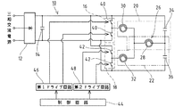
図1は、電磁誘導加熱装置の実施例としての電磁調理器の回路図を示すものであって、該電磁調理器10は、3相交流電源(例えば200V)の出力を整流して直流電圧に変換する整流器12と、該整流器12で整流された直流電圧を平滑する平滑コンデンサ14と、被加熱物38を加熱するコイル28,30,32を有する共振回路20,22およびスイッチング回路16,18とを基本的に備える。
FIG. 1 shows a circuit diagram of an electromagnetic cooker as an embodiment of an electromagnetic induction heating device, and the
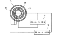
電磁調理器10の共振回路は、ワークコイル(加熱誘導コイル)と共振用コンデンサから構成されるものであって、実施例ではワークコイル26は、3つ以上(実施例では3つ)のコイル28,30,32を、略同一平面上において略同心円状に配置して構成される。最も内側に位置する基本コイル(第2のコイル)28に対し、中間に位置する第1コイル(第1のコイル)30および最も外側に位置する第2コイル(第1のコイル)32は何れも直列に接続されると共に、第1コイル30と第2コイル32とは並列に接続されている(図1参照)。また、基本コイル28に2つの共振用コンデンサ34,36が直列に接続されている。そして、基本コイル28と、該基本コイル28に直列接続される第1コイル30および第1共振用コンデンサ34で、第1共振回路20が構成される。更に、基本コイル28と、該基本コイル28に直列接続される第2コイル32および第2共振用コンデンサ36で、第2共振回路22が構成される。すなわち、実施例では、並列接続されているコイル30,32の数と同数に共振回路が分割されている。なお、ワークコイル26は、図示しない非導電性のトッププレートの下に配置されて、該トッププレートに載置されて磁気的に結合する鍋等の被加熱物38を電磁誘導により加熱するようになっている。
The resonance circuit of the
前記各コイル28,30,32は、多数の絶縁素線を撚り合わせたリッツ線を渦巻状に巻いて形成され、その巻き方向は全て同一(右巻きまたは左巻き)に設定されている。また、基本コイル28におけるリッツ線の素線数は、第1コイル30および第2コイル32の素線数よりも多く(例えば2倍に設定されるが、流れる電流に応じて温度上昇を抑制し得る値に設定すればよい)設定してある。
Each of the
電磁調理器10は、2つのスイッチング回路16,18を備えている。一方の第1スイッチング回路16は、前記平滑コンデンサ14に接続された一対の第1スイッチング素子40,40からなり、該第1スイッチング回路16が前記第1共振回路20を構成する第1コイル30に接続される。また他方の第2スイッチング回路18は、平滑コンデンサ14に接続された一対の第2スイッチング素子42,42からなり、該第2スイッチング回路18が前記第2共振回路22を構成する第2コイル32に接続される。第1スイッチング素子40,40と第2スイッチング素子42,42とは、平滑コンデンサ14に対して並列の関係で接続されている。そして、第1スイッチング回路16は、一対の第1スイッチング素子40,40を交互にオン/オフすることで、直流電圧から高周波電流を生成して第1共振回路20に供給する。また、第2スイッチング回路18は、一対の第2スイッチング素子42,42を交互にオン/オフすることで、直流電圧から高周波電流を生成して第2共振回路22に供給するようになっている。なお、スイッチング素子40,42としては、MOSFET,MOSIC,IGBT等が好適に使用される。
The
前記電磁調理器10の制御回路44には、前記第1スイッチング回路16を制御する第1ドライブ回路46および第2スイッチング回路18を制御する第2ドライブ回路48が接続されている。
A
前記基本コイル28と第1コイル30とのインダクタンスの比率、および基本コイル28と第2コイル32とのインダクタンスの比率は、何れも1:3〜1:4の範囲に設定される。基本コイル28の他のコイル(第1のコイル)30,32とのインダクタンスの比率が、前記1:4より小さい場合は、第1スイッチング回路16と第2スイッチング回路18との後述する負荷のバランス調整が最適に行なわれなくなる。逆に、基本コイル28の他のコイル30,32とのインダクタンスの比率が、前記1:3より大きい場合は、他のコイル30,32に比べてリッツ線の素線数を多くしている基本コイル28の線長(巻き数)が必要以上に長くなって、材料原価が高くなって経済的でなくなる。
The inductance ratio between the
前記基本コイル28と第1コイル30との第1総合インダクタンスと、基本コイル28と第2コイル32との第2総合インダクタンスとの差は、20%以内となるように設定される。これにより、第1スイッチング回路16および第2スイッチング回路18を同じタイミングでスイッチングすることが可能となり、各コイル28,30,32には同じ周波数の高周波電流が供給され、周波数の差異による騒音・振動(鍋鳴り)の発生を抑制し得る。なお、第1総合インダクタンスと第2総合インダクタンスとの差は20%以内であればよいが、同一となるよう設定するのが最も好適である。
The difference between the first total inductance of the
〔実施例の作用〕
次に、実施例に係る電磁調理器の作用につき説明する。
(Effects of Example)
Next, the operation of the electromagnetic cooker according to the embodiment will be described.
前記3相交流電源からの出力は、前記整流器12で整流して直流電圧に変換された後、前記平滑コンデンサ14で平滑される。前記制御回路44の制御下に、第1ドライブ回路46および第2ドライブ回路48から出力される信号によって第1スイッチング回路16および第2スイッチング回路18が制御される。すなわち、所定のタイミングで、一対の第1スイッチング素子40,40および一対の第2スイッチング素子42,42が夫々オン/オフ制御され、第1スイッチング回路16を介して第1共振回路20に高周波電流が供給されると共に、第2スイッチング回路18を介して第2共振回路22に高周波電流が供給される。第1共振回路20、すなわち基本コイル28と第1コイル30に高周波電流が供給されると、該コイル28,30に磁束が発生し、また第2共振回路22、すなわち基本コイル28と第2コイル32に高周波電流が供給されると、該コイル28,32に磁束が発生する。なお、基本コイル28には、直列に接続されている第1コイル30および第2コイル32を流れる高周波電流が複合して流れるが、基本コイル28のリッツ線の素線数は、第1コイル30および第2コイル32の素線数よりも多く設定してあるから、基本コイル28の温度上昇を軽減することができる。
The output from the three-phase AC power source is rectified by the
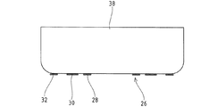
前記ワークコイル26を構成する3つのコイル28,30,32の全てに対して被加熱物38が磁気的に結合する状態(図3参照)で、該被加熱物38がトッププレートに載置されている場合は、各コイル28,30,32に発生する磁束によって被加熱物38に誘導電流が流れて該被加熱物38が加熱される。基本コイル28に直列接続される第1コイル30および第2コイル32は、並列に接続されているから、従来のように1つのコイルでワークコイルを形成した場合のように、ワークコイルの径方向で磁束が大きく変化するのは抑制され、被加熱物38に発生する誘導電流の分布を径方向で略均等にすることができ、被加熱物38の全体が均一に加熱される。
The
ここで、各コイル28,30,32に対する被加熱物38の磁気結合の状態の良否(コイルと被加熱物との離間距離の大小)によって、各コイル28,30,32に対する被加熱物38のインピーダンスが変化する。すなわち、磁気結合の良い状態ではインピーダンスが大きくなり、磁気結合の悪い状態ではインピーダンスが小さくなる。そして、実施例のように3つのコイル28,30,32を完全に独立していない構成では、各コイル28,30,32に対する被加熱物38のインピーダンスの変化に応じて前記スイッチング回路16,18に加わる負荷も変化し、各スイッチング回路16,18を介して対応する共振回路20,22に供給される高周波電流の値が、インピーダンスの値に応じて自動的に変動する。従って、各コイル28,30,32毎に被加熱物38に対する磁気結合の状態(コイル28,30,32に対する被加熱物38の位置)を検出する手段を設け、該検出手段によって検出した磁気結合の状態に応じて高周波電流の大きさを調整する必要はなく、検出手段や高周波電流を調整する手段を省略して構成を簡略化し得る。
Here, depending on the magnetic coupling state of the object to be heated 38 with respect to each
また、前記基本コイル28と第1コイル30とのインダクタンスの比率、および基本コイル28と第2コイル32とのインダクタンスの比率は、何れも1:3〜1:4の範囲に設定されている。従って、前述したインピーダンスの変化と、各コイル28,30,32に供給される高周波電流の値とは比例し、適正なバランス調整が達成される。しかも、基本コイル28と第1コイル30との第1総合インダクタンスと、基本コイル28と第2コイル32との第2総合インダクタンスとの差が、20%以内となるように設定してあるから、各コイル28,30,32に同じ周波数の高周波電流を供給して、騒音・振動(鍋鳴り)の発生を抑制することができる。
The inductance ratio between the
なお、前記ワークコイル26を構成する3つのコイル28,30,32の巻き方向が相互に逆向き(例えば、基本コイル28および第2コイルが右巻きで、第1コイル30が左巻きの場合等)となっていると、相互誘導により各スイッチング回路16,18に過電流が流れることがある。しかるに、実施例のワークコイル26を構成する3つのコイル28,30,32の巻き方向は同一となっているから、相互誘導によって各スイッチング回路16,18に過電流が流れるのを防止し得る。従って、スイッチング回路16,18を構成するスイッチング素子40,42として、定格電流および定格電圧の高いものを採用する必要はなく、コストを低減し得ると共に故障の発生率も低く抑えることができる。
The winding directions of the three
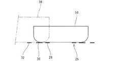
次に、前記ワークコイル26に対して被加熱物38の位置がずれ、図4に二点鎖線で示す如く、基本コイル28に対して磁気結合しない位置に被加熱物38が臨む状態では、基本コイル28は無負荷となる。しかるに、基本コイル28は第1コイル30および第2コイル32に直列に接続されているから、第1コイル30および第2コイル32に対して磁気結合している被加熱物38が、基本コイル28に対する負荷となり、第1スイッチング回路16および第2スイッチング回路18の何れにも過電流は流れず、各スイッチング素子40,42が故障するのを防止し得る。また、第1コイル30の外径以下の小型の被加熱物50を加熱する場合は、図4に実線で示すように、第2コイル32に対して小型の被加熱物50は磁気結合しない状態となるが、この場合も第2コイル32に直列接続されている基本コイル28には小型の被加熱物50が磁気結合しているから、第2スイッチング回路18に過電流が流れず、第2スイッチング素子42が故障するのを防止し得る。すなわち、被加熱物38,50の寸法の大小や位置ずれに対し、安全で効率的な加熱を達成し得る。しかも、各コイル28,30,32に対する被加熱物38,50の位置を検出して負荷の有無に応じて電力供給を入り・切りする必要はなく、制御系を簡略化し得る。
Next, in a state where the position of the object to be heated 38 is shifted with respect to the
また、各スイッチング回路16,18に過電流が流れるのを防止し得るから、各スイッチング回路16,18を構成するスイッチング素子40,42として、定格電流および定格電圧の低いものを使用することが可能となる。すなわち、製造コストを低廉に抑えることができると共に、スイッチング素子40,42自体の故障の発生率を低く抑制し得る。
In addition, since it is possible to prevent an overcurrent from flowing through the switching
実施例では、基本コイル28に対して第1コイル30および第2コイル32を直列接続することで、スイッチング回路については第1コイル30と第2コイル32に接続する2つで足り、全てのコイル28,30,32に対してスイッチング回路を設ける必要はなく、部品点数を低減し得る。
In the embodiment, the
〔変更例〕
本願は前述した実施例の構成に限定されるものでなく、その他の構成を適宜に採用することができる。
1. 実施例では、3つのコイルを用いたが、コイルを4つ以上とし、基本コイルに対して他のコイルの夫々を直列接続すると共に、他のコイル同士を並列の関係で接続するようにしてもよい。
2. 実施例では、基本コイルを最も内側に配置したが、該基本コイルの配設位置はこれに限らず、中間あるいは最も外側であってもよい。
3. 電磁調理器の電源としては、3相交流電源に限らず、商用電源(周波数50Hzもしくは60Hz)のAC100Vまたは単相200Vであってもよい。
4. 実施例では、各共振回路の夫々が専用の共振用コンデンサを備える場合で説明したが、例えば図1の回路図における基本コイルの左右両側に延在する配線における他の配線配線との接続点より基本コイル側に1つの共振用コンデンサを配設し、該1つの共振用コンデンサが各共振回路の共振用コンデンサとして兼用される構成を採用し得る。
[Example of change]
The present application is not limited to the configuration of the above-described embodiment, and other configurations can be appropriately employed.
1. In the embodiment, three coils are used. However, the number of coils is four or more, and the other coils are connected in series to the basic coil, and the other coils are connected in parallel. Good.
2. In the embodiment, the basic coil is arranged on the innermost side, but the arrangement position of the basic coil is not limited to this, and may be the middle or the outermost side.
3. The power source of the electromagnetic cooker is not limited to a three-phase AC power source, and may be a commercial power source (
4). In the embodiment, each resonance circuit is described as having a dedicated resonance capacitor. For example, from the connection point with other wiring lines in the wiring extending on the left and right sides of the basic coil in the circuit diagram of FIG. A configuration may be employed in which one resonance capacitor is disposed on the basic coil side, and the one resonance capacitor is also used as a resonance capacitor for each resonance circuit.
16 第1スイッチング回路(スイッチング回路)
18 第2スイッチング回路(スイッチング回路),20 第1共振回路(共振回路)
22 第2共振回路(共振回路),26 ワークコイル(誘導加熱コイル)
28 基本コイル(第2のコイル),30 第1コイル(第1のコイル)
32 第2コイル(第1のコイル),38 被加熱物
16 First switching circuit (switching circuit)
18 Second switching circuit (switching circuit), 20 First resonance circuit (resonance circuit)
22 2nd resonance circuit (resonance circuit), 26 Work coil (induction heating coil)
28 Basic coil (second coil), 30 First coil (first coil)
32 Second coil (first coil), 38 Object to be heated
Claims (5)
前記誘導加熱コイル(26)は、相互に並列接続される複数の第1のコイル(30,32)と、各第1のコイル(30,32)に直列接続される第2のコイル(28)とを備え、各コイル(28,30,32)が略同一平面上に略同心で配置され、
前記共振回路は、各第1のコイル(30,32)および第2のコイル(28)を組として分割され、
前記各共振回路(20,22)毎に、独立する前記スイッチング回路(16,18)が接続される
ことを特徴とする電磁誘導加熱装置。 In an electromagnetic induction heating apparatus comprising a resonance circuit having an induction heating coil (26) for heating an object to be heated (38), and a switching circuit for supplying a high-frequency current to the resonance circuit,
The induction heating coil (26) includes a plurality of first coils (30, 32) connected in parallel to each other and a second coil (28) connected in series to each first coil (30, 32). Each coil (28, 30, 32) is arranged substantially concentrically on the same plane,
The resonant circuit is divided into a set of the first coil (30, 32) and the second coil (28),
The electromagnetic induction heating device, wherein the independent switching circuit (16, 18) is connected to each of the resonance circuits (20, 22).
Priority Applications (6)
| Application Number | Priority Date | Filing Date | Title |
|---|---|---|---|
| JP2007336996A JP5052329B2 (en) | 2007-12-27 | 2007-12-27 | Electromagnetic induction heating device |
| US12/735,158 US8299407B2 (en) | 2007-12-27 | 2008-11-07 | Electromagnetic induction heating device |
| PCT/JP2008/070353 WO2009084328A1 (en) | 2007-12-27 | 2008-11-07 | Electromagnetic induction heating device |
| CN2008801229932A CN101911829B (en) | 2007-12-27 | 2008-11-07 | Electromagnetic induction heating device |
| EP08868633A EP2237641B1 (en) | 2007-12-27 | 2008-11-07 | Electromagnetic induction heating device |
| AT08868633T ATE542394T1 (en) | 2007-12-27 | 2008-11-07 | ELECTROMAGNETIC INDUCTION HEATING DEVICE |
Applications Claiming Priority (1)
| Application Number | Priority Date | Filing Date | Title |
|---|---|---|---|
| JP2007336996A JP5052329B2 (en) | 2007-12-27 | 2007-12-27 | Electromagnetic induction heating device |
Publications (2)
| Publication Number | Publication Date |
|---|---|
| JP2009158366A true JP2009158366A (en) | 2009-07-16 |
| JP5052329B2 JP5052329B2 (en) | 2012-10-17 |
Family
ID=40824051
Family Applications (1)
| Application Number | Title | Priority Date | Filing Date |
|---|---|---|---|
| JP2007336996A Expired - Fee Related JP5052329B2 (en) | 2007-12-27 | 2007-12-27 | Electromagnetic induction heating device |
Country Status (6)
| Country | Link |
|---|---|
| US (1) | US8299407B2 (en) |
| EP (1) | EP2237641B1 (en) |
| JP (1) | JP5052329B2 (en) |
| CN (1) | CN101911829B (en) |
| AT (1) | ATE542394T1 (en) |
| WO (1) | WO2009084328A1 (en) |
Cited By (4)
| Publication number | Priority date | Publication date | Assignee | Title |
|---|---|---|---|---|
| US20120205365A1 (en) * | 2009-10-26 | 2012-08-16 | BSH Bosch und Siemens Hausgeräte GmbH | Cook top comprising at least two heating elements and a power electronics arrangement |
| JP2012253018A (en) * | 2011-06-03 | 2012-12-20 | General Electric Co <Ge> | Device and system for induction heating |
| JP2013171708A (en) * | 2012-02-21 | 2013-09-02 | Mitsubishi Electric Corp | Induction heating cooker |
| US9510397B2 (en) | 2011-09-01 | 2016-11-29 | Toyo Seikan Group Holdings, Ltd. | High-frequency induction heating apparatus and film label attaching apparatus |
Families Citing this family (18)
| Publication number | Priority date | Publication date | Assignee | Title |
|---|---|---|---|---|
| ES2678069T3 (en) * | 2010-11-16 | 2018-08-08 | Mitsubishi Electric Corporation | Induction heating cooking system and process to control it |
| EP2706817B1 (en) * | 2012-09-07 | 2016-03-30 | BSH Hausgeräte GmbH | Cooking hob |
| CN103841679B (en) * | 2012-11-26 | 2017-09-05 | 松下电器产业株式会社 | Induction heating device and rice cooker using the induction heating device |
| US10973368B2 (en) | 2012-12-12 | 2021-04-13 | The Vollrath Company, L.L.C. | Three dimensional induction rethermalizing stations and control systems |
| US9307862B2 (en) | 2012-12-12 | 2016-04-12 | The Vollrath Company, L.L.C. | Three dimentional induction rethermalizing station and control system |
| JP5844017B1 (en) * | 2014-04-16 | 2016-01-13 | 三菱電機株式会社 | Induction heating cooker and control method thereof |
| JP2016149867A (en) * | 2015-02-12 | 2016-08-18 | 富士通株式会社 | Resonant switching power supply, control method thereof, and program thereof |
| JP6589545B2 (en) * | 2015-10-16 | 2019-10-16 | シンフォニアテクノロジー株式会社 | Induction heating device |
| US20170164777A1 (en) * | 2015-12-10 | 2017-06-15 | Spectrum Brands, Inc. | Induction cooktop |
| CN108135043B (en) * | 2017-12-26 | 2024-06-04 | 深圳国创名厨商用设备制造有限公司 | Single-layer electromagnetic wire coil capable of changing heating area |
| US11219101B2 (en) * | 2018-05-03 | 2022-01-04 | Haier Us Appliance Solutions, Inc. | Induction cooking appliance having multiple heating coils |
| KR102653030B1 (en) * | 2018-11-19 | 2024-03-28 | 엘지전자 주식회사 | A method for detecting vessel of induction heating device to which three-phase power is applied |
| JP7154321B2 (en) * | 2019-02-15 | 2022-10-17 | 三菱電機株式会社 | induction cooker |
| CN110636658A (en) * | 2019-11-08 | 2019-12-31 | 惠州学院 | An electromagnetic induction heating module and heating equipment |
| WO2021111169A1 (en) * | 2019-12-03 | 2021-06-10 | Budagaschwili Wachtang | Inductive heating device, in particular inductive immersion heater |
| KR102767730B1 (en) * | 2020-03-05 | 2025-02-12 | 엘지전자 주식회사 | Power converting device and home appliance including the same |
| CN114698166B (en) * | 2020-12-29 | 2023-06-16 | 佛山市顺德区美的电热电器制造有限公司 | Electromagnetic heating apparatus, noise suppressing method, heating control system, and storage medium |
| EP4122685B1 (en) | 2021-07-23 | 2023-12-27 | Corebon AB | Molding tool, method of manufacturing the same and method of producing a composite part in said tool |
Citations (4)
| Publication number | Priority date | Publication date | Assignee | Title |
|---|---|---|---|---|
| JPH02189886A (en) * | 1989-01-18 | 1990-07-25 | Nakamura Yoshihiko | High frequency induction heating device with transistor |
| JP2000091063A (en) * | 1998-09-11 | 2000-03-31 | Mitsubishi Electric Corp | Electromagnetic induction heating device |
| JP2003151751A (en) * | 2001-11-08 | 2003-05-23 | Mitsubishi Electric Corp | Induction heating cooker |
| JP2007194229A (en) * | 2007-04-27 | 2007-08-02 | Hitachi Appliances Inc | Electromagnetic induction heating device |
Family Cites Families (10)
| Publication number | Priority date | Publication date | Assignee | Title |
|---|---|---|---|---|
| JPS62119892A (en) * | 1985-11-20 | 1987-06-01 | 松下電器産業株式会社 | Induction heating cooker inverter |
| JPS635582A (en) * | 1986-06-25 | 1988-01-11 | Fujitsu Ltd | System for driving josephson logic circuit |
| JPS6355882A (en) * | 1986-08-27 | 1988-03-10 | 松下電器産業株式会社 | Heating coil for induction cooker |
| JPH07106172B2 (en) * | 1990-12-28 | 1995-11-15 | タイガー魔法瓶株式会社 | Electromagnetic heating container |
| FR2672763B1 (en) * | 1991-02-08 | 1993-05-07 | Bonnet Sa | INDUCING DEVICE FOR INDUCTION HEATING OF KITCHEN CONTAINERS AND METHOD FOR CONTROLLING SUCH A DEVICE. |
| FR2728132A1 (en) * | 1994-12-09 | 1996-06-14 | Bonnet Sa | DEVICE FOR HEATING BY INDUCTION OF CONTAINER AND METHOD FOR CONTROLLING SUCH A DEVICE |
| FR2806868B1 (en) * | 2000-03-21 | 2002-06-28 | Brandt Cooking | DEVICE FOR HEATING BY INDUCTION OF CULINARY CONTAINER |
| US7105783B2 (en) * | 2003-03-25 | 2006-09-12 | Kabuhsiki Kaisha Toshiba | Fixing device using induction heating |
| JP2007257977A (en) | 2006-03-23 | 2007-10-04 | Matsushita Electric Ind Co Ltd | Electromagnetic cooker |
| FR2902600B1 (en) * | 2006-06-14 | 2008-09-05 | Brandt Ind Sas | INDUCTION SYSTEM, METHOD FOR SUPPLYING AN INDUCTOR AND COOKTOP HAVING SUCH A SYSTEM |
-
2007
- 2007-12-27 JP JP2007336996A patent/JP5052329B2/en not_active Expired - Fee Related
-
2008
- 2008-11-07 CN CN2008801229932A patent/CN101911829B/en not_active Expired - Fee Related
- 2008-11-07 WO PCT/JP2008/070353 patent/WO2009084328A1/en not_active Ceased
- 2008-11-07 AT AT08868633T patent/ATE542394T1/en active
- 2008-11-07 US US12/735,158 patent/US8299407B2/en not_active Expired - Fee Related
- 2008-11-07 EP EP08868633A patent/EP2237641B1/en not_active Not-in-force
Patent Citations (4)
| Publication number | Priority date | Publication date | Assignee | Title |
|---|---|---|---|---|
| JPH02189886A (en) * | 1989-01-18 | 1990-07-25 | Nakamura Yoshihiko | High frequency induction heating device with transistor |
| JP2000091063A (en) * | 1998-09-11 | 2000-03-31 | Mitsubishi Electric Corp | Electromagnetic induction heating device |
| JP2003151751A (en) * | 2001-11-08 | 2003-05-23 | Mitsubishi Electric Corp | Induction heating cooker |
| JP2007194229A (en) * | 2007-04-27 | 2007-08-02 | Hitachi Appliances Inc | Electromagnetic induction heating device |
Cited By (5)
| Publication number | Priority date | Publication date | Assignee | Title |
|---|---|---|---|---|
| US20120205365A1 (en) * | 2009-10-26 | 2012-08-16 | BSH Bosch und Siemens Hausgeräte GmbH | Cook top comprising at least two heating elements and a power electronics arrangement |
| US10925122B2 (en) * | 2009-10-26 | 2021-02-16 | BSH Hausgeräte GmbH | Cook top comprising at least two heating elements and a power electronics arrangement |
| JP2012253018A (en) * | 2011-06-03 | 2012-12-20 | General Electric Co <Ge> | Device and system for induction heating |
| US9510397B2 (en) | 2011-09-01 | 2016-11-29 | Toyo Seikan Group Holdings, Ltd. | High-frequency induction heating apparatus and film label attaching apparatus |
| JP2013171708A (en) * | 2012-02-21 | 2013-09-02 | Mitsubishi Electric Corp | Induction heating cooker |
Also Published As
| Publication number | Publication date |
|---|---|
| US20100258556A1 (en) | 2010-10-14 |
| CN101911829A (en) | 2010-12-08 |
| EP2237641B1 (en) | 2012-01-18 |
| ATE542394T1 (en) | 2012-02-15 |
| WO2009084328A1 (en) | 2009-07-09 |
| EP2237641A4 (en) | 2010-12-22 |
| CN101911829B (en) | 2013-11-06 |
| US8299407B2 (en) | 2012-10-30 |
| JP5052329B2 (en) | 2012-10-17 |
| EP2237641A1 (en) | 2010-10-06 |
Similar Documents
| Publication | Publication Date | Title |
|---|---|---|
| JP5052329B2 (en) | Electromagnetic induction heating device | |
| JP5025698B2 (en) | Induction heating device | |
| JP5844017B1 (en) | Induction heating cooker and control method thereof | |
| JP5909675B2 (en) | Induction heating cooker | |
| WO2011089900A1 (en) | Induction heating apparatus | |
| JP2015136287A5 (en) | ||
| JP7186344B2 (en) | induction heating device | |
| CN103841679B (en) | Induction heating device and rice cooker using the induction heating device | |
| CN108141921A (en) | Induction heating apparatus and its control method | |
| JP5807161B2 (en) | Induction heating apparatus and rice cooker using the same | |
| JP2016207544A (en) | Induction heating cooker | |
| JP2011171040A (en) | Induction heating device, and induction heating cooking apparatus with the same | |
| JP5369878B2 (en) | Induction heating device | |
| US11160144B2 (en) | Modular transformers and induction heating systems having modular transformers | |
| JP5734390B2 (en) | Induction heating cooker | |
| KR101371009B1 (en) | A system of reducing energe for high frequence inductoin heating device | |
| JP6150206B2 (en) | Induction heating system and power supply method | |
| JP2014175277A (en) | Induction heating cooker | |
| JP2020004625A (en) | Electromagnetic induction device | |
| JP2011150799A (en) | Induction heating apparatus | |
| Cook et al. | Transformer design and load matching | |
| JP2012010463A (en) | Switching power supply apparatus | |
| US20210043374A1 (en) | Insulated winding wire transformer for welding-type power supplies | |
| JP5500296B2 (en) | Induction heating device | |
| JP2014049431A (en) | Induction heating cooker |
Legal Events
| Date | Code | Title | Description |
|---|---|---|---|
| A621 | Written request for application examination |
Free format text: JAPANESE INTERMEDIATE CODE: A621 Effective date: 20101115 |
|
| TRDD | Decision of grant or rejection written | ||
| A01 | Written decision to grant a patent or to grant a registration (utility model) |
Free format text: JAPANESE INTERMEDIATE CODE: A01 Effective date: 20120710 |
|
| A01 | Written decision to grant a patent or to grant a registration (utility model) |
Free format text: JAPANESE INTERMEDIATE CODE: A01 |
|
| A61 | First payment of annual fees (during grant procedure) |
Free format text: JAPANESE INTERMEDIATE CODE: A61 Effective date: 20120724 |
|
| R150 | Certificate of patent or registration of utility model |
Ref document number: 5052329 Country of ref document: JP Free format text: JAPANESE INTERMEDIATE CODE: R150 Free format text: JAPANESE INTERMEDIATE CODE: R150 |
|
| FPAY | Renewal fee payment (event date is renewal date of database) |
Free format text: PAYMENT UNTIL: 20150803 Year of fee payment: 3 |
|
| S533 | Written request for registration of change of name |
Free format text: JAPANESE INTERMEDIATE CODE: R313533 |
|
| R350 | Written notification of registration of transfer |
Free format text: JAPANESE INTERMEDIATE CODE: R350 |
|
| LAPS | Cancellation because of no payment of annual fees |