JP2009156183A - Engine seal structure, resin ring, and engine - Google Patents
Engine seal structure, resin ring, and engine Download PDFInfo
- Publication number
- JP2009156183A JP2009156183A JP2007336120A JP2007336120A JP2009156183A JP 2009156183 A JP2009156183 A JP 2009156183A JP 2007336120 A JP2007336120 A JP 2007336120A JP 2007336120 A JP2007336120 A JP 2007336120A JP 2009156183 A JP2009156183 A JP 2009156183A
- Authority
- JP
- Japan
- Prior art keywords
- engine
- seal structure
- ring
- cylinder liner
- resin ring
- Prior art date
- Legal status (The legal status is an assumption and is not a legal conclusion. Google has not performed a legal analysis and makes no representation as to the accuracy of the status listed.)
- Granted
Links
Images


Landscapes
- Cylinder Crankcases Of Internal Combustion Engines (AREA)
- Pistons, Piston Rings, And Cylinders (AREA)
Abstract
Description
本発明は、エンジンのシール構造、樹脂リング、およびエンジンに係り、特に水冷式エンジンにおいて、シリンダライナとシリンダブロックとの間に形成されたウォータジャケット部分に用いられるエンジンのシール構造、樹脂リング、および該シール構造が適用されたエンジンに関する。 The present invention relates to an engine seal structure, a resin ring, and an engine, and more particularly to an engine seal structure, a resin ring, and an engine used in a water jacket portion formed between a cylinder liner and a cylinder block in a water-cooled engine. The present invention relates to an engine to which the seal structure is applied.
従来、水冷式エンジンにおいて、シリンダブロックとシリンダライナとの間に形成されたウォータジャケットには、ラジエータとの間でエンジン冷却用の冷却水が循環している。シリンダライナには、この冷却水の漏れを防止するための角形シールリングが設けられている(特許文献1)。 Conventionally, in a water-cooled engine, cooling water for engine cooling circulates between a radiator and a water jacket formed between a cylinder block and a cylinder liner. The cylinder liner is provided with a square seal ring for preventing leakage of the cooling water (Patent Document 1).
ところで近年、本発明者は、エンジンの高出力化、高筒内圧化に伴って、ピストンのスラスト方向の振動により、ウォータジャケット内の冷却水に大きな圧力振動が生じ、キャビテーションが発生することを見出した。そのため、従来のシール構造では、冷却水に面している角形シールリングがキャビテーションにより損傷し、冷却水の漏れが生じるという可能性がある。 By the way, in recent years, the present inventor has found that, as the engine output increases and the in-cylinder pressure increases, vibration in the thrust direction of the piston causes a large pressure vibration in the cooling water in the water jacket, resulting in cavitation. It was. Therefore, in the conventional seal structure, there is a possibility that the rectangular seal ring facing the cooling water is damaged by cavitation and leakage of the cooling water occurs.
本発明の目的は、キャビテーションの影響を受けにくくできるエンジンのシール構造、樹脂リング、およびエンジンを提供することにある。 An object of the present invention is to provide an engine seal structure, a resin ring, and an engine that can be hardly affected by cavitation.
本発明の請求項1に係るエンジンのシール構造は、水冷式エンジンのシリンダライナに装着されるとともに、このシリンダライナとシリンダブロックとの間に形成されたウォータジャケットに臨む樹脂リングを有するシール構造であって、前記樹脂リングは、熱可塑性樹脂製により形成され、かつ周方向の途中が切断部によって切断されており、前記切断部は、エンジンスラスト方向から外れて位置していることを特徴とする。
ここで、「エンジンスラスト方向」とは、クランクシャフトの軸線方向およびシリンダライナの軸線方向に対して直交する方向をいう。
An engine seal structure according to
Here, the “engine thrust direction” refers to a direction orthogonal to the axial direction of the crankshaft and the axial direction of the cylinder liner.
本発明の請求項2に係るエンジンのシール構造は、請求項1に記載のエンジンのシール構造において、前記ウォータジャケットに臨む側とは反対側では、前記樹脂リングにゴム製のシールリングが接していることを特徴とする。
ここで、「接している」とは、単に樹脂リングとシールリングとが接しているほかに、樹脂リングとシールリングとが接着剤等で接着されているか、または一体に成形されている場合も含む。
The engine seal structure according to
Here, “contact” means that the resin ring and the seal ring are not in contact with each other, but the resin ring and the seal ring may be bonded with an adhesive or the like, or may be integrally formed. Including.
本発明の請求項3に係るエンジンのシール構造は、請求項1または請求項2に記載のエンジンのシール構造において、前記シリンダライナは前記シリンダブロックに圧入されるとともに、前記樹脂リングが装着される凹部が周方向に沿って設けられ、この凹部内にはラウンド状の角部が設けられ、前記樹脂リングには、前記シリンダライナの圧入方向の前方側の外周部分に面取り部が、圧入方向の後方側の内周部分に曲面部がそれぞれ設けられ、この樹脂リングの曲面部が前記凹部内の角部に密接することを特徴とする。
The engine seal structure according to
本発明の請求項4に係るエンジンのシール構造は、請求項1〜3のいずれかに記載のエンジンのシール構造において、前記切断部によって切断されることで形成される切断面は、前記シリンダライナの軸線方向および径方向の少なくともいずれか一方に対して交差して形成されていることを特徴とする。 The engine seal structure according to a fourth aspect of the present invention is the engine seal structure according to any one of the first to third aspects, wherein the cut surface formed by being cut by the cutting portion is the cylinder liner. It is formed so as to intersect with at least one of the axial direction and the radial direction.
本発明の請求項5に係るエンジンのシール構造は、請求項1〜4のいずれかに記載のエンジンのシール構造において、前記エンジンスラスト方向に対して周方向の前後30°の範囲を外れて前記切断部が位置していることを特徴とする。 An engine seal structure according to a fifth aspect of the present invention is the engine seal structure according to any one of the first to fourth aspects, wherein the engine seal structure deviates from a range of 30 ° in the circumferential direction with respect to the engine thrust direction. The cutting part is located.
本発明の請求項6に係る樹脂リングは、請求項1〜5のいずれかに記載のエンジンのシール構造に用いられることを特徴とする。
The resin ring which concerns on
本発明の請求項7に係るエンジンは、請求項1〜5のいずれかに記載のエンジンのシール構造が採用されていることを特徴とする。
An engine according to claim 7 of the present invention is characterized in that the engine seal structure according to any one of
以上において、請求項1および請求項6,7の発明によれば、樹脂リングは弾性が小さく、ゴム製に比してより硬質の熱可塑性樹脂製で形成されているため、ウォータジャケット内で発生するキャビテーションにより損傷するおそれがない。また、樹脂リングが硬質であることにより、シリンダライナへの装着性が課題となるが、樹脂リングの周方向の途中が切断されているため、硬質の熱可塑性樹脂製で形成されているにも関わらず、シリンダライナへ樹脂リングを広げて容易に装着できる。さらに、切断部をキャビテーションの発生し易いエンジンスラスト方向から外れて位置することで、切断部はキャビテーションの影響を回避でき、キャビテーションが切断部を通して他に影響を及ぼすことがない。 In the above, according to the first and sixth and seventh aspects of the present invention, the resin ring has a low elasticity and is formed of a harder thermoplastic resin than that of rubber, so that it occurs in the water jacket. There is no risk of damage due to cavitation. Moreover, since the resin ring is hard, the mounting property to the cylinder liner becomes a problem, but since the middle of the resin ring in the circumferential direction is cut, it is also made of a hard thermoplastic resin. Regardless, the resin ring can be easily mounted on the cylinder liner. Furthermore, by positioning the cutting portion away from the engine thrust direction where cavitation is likely to occur, the cutting portion can avoid the influence of cavitation, and cavitation does not affect the other through the cutting portion.
請求項2の発明によれば、樹脂リングのウォータジャケットに臨む側とは反対の位置にシールリングを配置することで、シールリングがウォータジャケットに臨むことがないため、シールリングがウォータジャケット内へはみだすことを防止できる。さらに、弾性の大きいゴム製のシールリングを用いたことで、冷却水の漏れを確実に防止できる。また、樹脂リングの切断部をキャビテーションの影響が少ない位置に配置したことで、シールリングは切断部からキャビテーションの影響を受けることなく、損傷を防止できる。 According to the second aspect of the present invention, since the seal ring does not face the water jacket by disposing the seal ring at a position opposite to the side facing the water jacket of the resin ring, the seal ring enters the water jacket. It can be prevented from protruding. Furthermore, the use of a rubber seal ring with high elasticity can reliably prevent leakage of cooling water. Further, by disposing the cut portion of the resin ring at a position where the influence of cavitation is small, the seal ring can be prevented from being damaged without being affected by the cavitation from the cut portion.
請求項3の発明によれば、樹脂リングには面取り部が設けられていることで、樹脂リングが装着されたシリンダライナをシリンダブロックに圧入する際、樹脂リングをウォータジャケットに引っ掛かることなく、スムースに押し込むことができる。また、樹脂リングには曲面部が設けられているため、シリンダライナを圧入した状態において、シリンダライナの凹部にある角部へ曲面部を密接させることで、樹脂リングを凹部内に良好に保持できる。
According to the invention of
請求項4の発明によれば、シリンダライナの軸線方向および径方向の少なくともいずれか一方に対して切断面が交差していることで、切断面にてキャビテーションの進行を遮断でき、シールリングへのキャビテーションの影響を防止できる。 According to the fourth aspect of the present invention, since the cut surface intersects at least one of the axial direction and the radial direction of the cylinder liner, the progress of cavitation can be blocked at the cut surface, The influence of cavitation can be prevented.
請求項5の発明によれば、エンジンスラスト方向では特にキャビテーションが発生し易いが、エンジンスラスト方向からさらに前後30°の範囲を外れて切断部が位置していることで、切断部へのキャビテーションの影響を確実に回避できる。よって、樹脂リングに切断部を形成しても、切断部を介して他にキャビテーションの影響を及ぼすのをより確実に防止できる。 According to the fifth aspect of the present invention, cavitation is particularly likely to occur in the engine thrust direction. However, since the cutting portion is located outside the range of 30 ° forward and backward from the engine thrust direction, the cavitation to the cutting portion is The impact can be avoided reliably. Therefore, even if the cut portion is formed in the resin ring, it is possible to more reliably prevent the influence of cavitation from being exerted through the cut portion.
以下、本発明に係る一実施形態を図面に基づいて説明する。
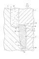
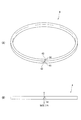
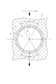
図1は、本実施形態でのシール構造が適用された水冷式エンジン10を示す断面図であり、図2は、シール構造の要部を示す断面図である。図3(A)は、シール構造を構成する樹脂リングとしてのバックアップリング4の斜視図であり、図3(B)は、バックアップリング4の正面図である。図4は、図1のIV−IV線でのシリンダブロック2の断面図である。
Hereinafter, an embodiment according to the present invention will be described with reference to the drawings.
FIG. 1 is a cross-sectional view showing a water-cooled
図1,2に示すシール構造において、水冷式エンジン10のシリンダライナ1とシリンダブロック2との間には、エンジン冷却用のウォータジャケット3がシリンダライナ1の外周を取り囲むように形成されている。円筒状のシリンダライナ1の内側は、図示しないピストンが往復動するシリンダ空間11となっており、シリンダライナ1の外周には、周方向に連続した複数の凹部12が上下に所定間隔で設けられている。
1 and 2, a
最も上部側(シリンダヘッド側)の凹部12内には、上側にバックアップリング4および下側にシールリングとしての角形シールリング5が配置され、他の凹部12には、ゴムシール6が配置されている。また、ウォータジャケット3には、図示しないラジエータとの間でエンジン冷却用の冷却水31が循環している。
In the
ここで、バックアップリング4は、弾性が小さく、かつ耐熱性および耐水性に優れた熱可塑性樹脂製で形成されている。このようなバックアップリング4は、角形シールリング5のウォータジャケット3側へのはみ出しを防止するとともに、角形シールリング5に対してキャビテーションの影響を軽減するために用いられており、バックアップリング4自身としても、材質的にキャビテーションの影響をほとんど受けることはない。
Here, the
バックアップリング4の材質としては、本実施形態では、ポリテトラフルオロエチレンを採用しているが、これに限らず、ポリエチレン、ポリプロピレン、ポリスチレン、アクリロトリル、ブタンジエン、スチレン樹脂、ポリ塩化ビニル、アクリロ二トリル、スチレン樹脂、メタクリル樹脂、塩化ビニル、ポリアミド、ポリアセタール、ポリカーボネート、変性ポリフェニレンエーテル、ポリブチレンテレフタレート、GF強化ポリエチレンテレフタレート、超高分子量ポリエチレン、ポリフェニレンスルフィド、ポリイミド、ポリエーテルイミド、ポリアリレート、ポリスルホン、ポリエーテルスルホン、ポリエーテルエーテルケトン、液晶ポリマー等の熱可塑性樹脂の中から耐熱性などを勘案して任意に採用してよい。
As the material of the
角形シールリング5は、弾性を有する合成ゴム製であり、凹部12に収容された状態において、シリンダブロック2の壁面21によって潰される潰れ代を有した外径寸法に形成されている。このような角形シールリング5は、冷却水31がシリンダブロック2の下方側(シリンダヘッドとは反対側)への漏れるのを防止するために用いられている。なお、ゴムシール6は、シリンダブロック2の下部側から潤滑油が角形シールリング5側への入り込むのを防止するものであり、弾性を有する合成ゴム製で形成されている。
The
図2を参照すると、凹部12とシリンダブロック2の壁面21とによって形成された空間121の断面形状は、下方向に向かうに従って楔状に狭くなっている。これによれば、凹部12にバックアップリング4および角形シールリング5を配置した後に、シリンダライナ1をシリンダブロック2に圧入すると(図2での白抜き矢印方向)、角形シールリング5は、潰れ代部分が壁面21により押圧されて圧縮され、空間121内に良好に密接して、冷却水31の水漏れを確実に防止することとなる。
Referring to FIG. 2, the cross-sectional shape of the
つまり、シリンダライナ1をシリンダブロック2の段差部23(図1)に当接する位置まで圧入すると、角形シールリング5は、壁面21に押圧されながら圧縮し、壁面21とシリンダライナ1とに良好に密着し、冷却水31の漏れを確実に防止する。また、角形シールリング5は、壁面21からの反力により、バックアップリング4を押圧する。バックアップリング4は角形シールリング5に押圧されることで、バックアップリング4の内周側に設けられた曲面部43が凹部12に設けられたラウンド状の角部122に良好に密着し、より安定した状態に保持される。
That is, when the
次に、バックアップリング4の形状および配置方向について説明する。
図3(A),(B)に示すように、バックアップリング4の周方向の途中には切断部41が設けられている。切断部41によりバックアップリング4は、正面視した場合にシリンダライナ1の軸線方向に対して適宜な角度で切断されている。すなわち、切断面44は、シリンダライナ1の軸線方向に対して交差するように切断されている。バックアップリング4の一箇所を切断することで、弾性の小さいバックアップリング4を広げながら凹部12に容易に装着できる。なお、図3(A)では、切断面44が見えるようにバックアップリング4を開きぎみにして、図示している。
Next, the shape and arrangement direction of the
As shown in FIGS. 3A and 3B, a cutting
図3(A)および図2に示すように、シリンダライナ2の圧入方向の前方側となるバックアップリング4の下側外周部分には、周方向に連続した面取り部42が形成され、シリンダライナ2の圧入方向の後方側となるバックアップリング4の上側内周部分には、周方向に連続した前述の曲面部43が形成されている。面取り部42により、圧入途中でのシリンダブロック2側に設けられた角部22に対する引っ掛かりをなくし、バックアップリング4がスムースに押し込まれるようになっている。角形シールリング5に設けた面取り部51も同様に作用する。曲面部43は、シリンダライナ1がシリンダブロック2へ圧入された際に凹部12内の角部122と密接する。
As shown in FIGS. 3A and 2, a chamfered
図4を参照すると、バックアップリング4は、シリンダライナ1に装着された状態において、切断部41がエンジンスラスト方向(図示しないクランクシャフトの軸線方向およびシリンダライナ1の軸線方向の両方向に対して直交する方向)から外れて位置している。本実施形態では、切断部41はエンジンスラスト方向から周方向に90°ずれた位置、つまりクランクシャフトの軸線A−Aに対応して位置している。
Referring to FIG. 4, when the
エンジンスラスト方向では、ピストンの往復動に伴う振動発生により、ウォータジャケット3内でキャビテーションが発生し易い。このため、切断部41をキャビテーションの影響を受けるエンジンスラスト方向に位置させると、切断部41の切り口から下方に位置する角形シールリング5にキャビテーションの影響を与えるおそれがある。すなわち、本実施形態では、切断部41をエンジンスラスト方向から外れて位置させることで、切断部41を介しての角形シールリング5へのキャビテーションの影響をなくしているのである。ここで、切断部41の位置はエンジンスラスト方向から外れていればよいが、好ましくは、エンジンスラスト方向に対して周方向の前後30°から外れて位置させることがよく、より好ましくは、本実施形態のように、クランクシャフトの軸線A−Aに対応させるのがよい。
In the engine thrust direction, cavitation is likely to occur in the
なお、本発明は前述の実施形態に限定されるものではなく、本発明の目的を達成できる他の構成などを含み、以下に示すような変形なども本発明に含まれるものである。
例えば、前記実施形態では、バックアップリング4は、切断部41により正面視した状態で斜めに切断されていたが、シリンダライナ1の軸線方向に沿って図中鉛直に切断されてもよい。これによっても、シリンダライナ1へ装着が容易であり、エンジンスラスト方向を外して切断部41を位置させることで、角形シールリング5は切断部41を介してキャビテーションの影響を受けることがない。
Note that the present invention is not limited to the above-described embodiment, and includes other configurations that can achieve the object of the present invention, and includes the following modifications and the like.
For example, in the above-described embodiment, the
前記実施形態では、バックアップリング4と角形シールリング5とがそれぞれ別体とされ、互いに単に接している構成であったが、接着剤等で互いに接着されていてもよく、またバックアップリング4と角形シールリング5とが一体成型されていてもよい。これらの場合においても、バックアップリング4に相当する部分のみを破断することで、前述したようにキャビテーションの影響を受けることがなく、シリンダライナ1に容易に装着できる。
In the above-described embodiment, the
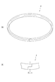
さらに、切断部41の形状は、図5、図6に示すような形状でもよい。図5(A),(B)のバックアップリング4は、切断部41により平面視した状態でクランク状に切断され、図6(A),(B)のバックアップリング4は、切断部41により平面視した状態で径方向に対して斜めに切断されたものである。これらの場合もバックアップリング4は、シリンダライナ1の径方向に対して交差する切断面を有している。また、図5でのバックアップリング4は、平面視した状態でクランク状に切断されたが、正面視した状態でクランク状に切断されてもよい。この場合には、シリンダライナ1の軸線方向に対して交差する切断面を有することになる。
Further, the shape of the cutting
前記実施形態では、エンジンスラスト方向を外した位置に切断部41を配置したが、図7には、参考として、切断部41をエンジンスラスト方向に位置させる場合が示されている。この場合のバックアップリング4としては、切断部41により平面視または正面視において、例えば、斜めに切断されているか、またはクランク状に切断されているかである。すなわち、バックアップリング4は、切断部41により形成された切断面がシリンダライナ1の軸線方向または径方向に対して交差するように切断されていなければよい。切断部41での切断面がシリンダライナ1の軸線方向または径方向に沿っていると、発生したキャビテーションの影響が切断部41を通して下方の角形シールリング5に及ぼすことになる。
In the above-described embodiment, the cutting
これに対して、切断部41での切断面が前述したように斜めであったり、クランク状であれば、シリンダライナ1の軸線方向または径方向に沿って進行したり、バックアップリング4の外周側から内周側に向けて進行しようとするキャビテーションでの損傷を切断面にて遮ることができ、角形シールリング5が受けるキャビテーションの影響を軽減できる。従って、キャビテーションの発生し易いエンジンスラスト方向上に切断部41を配置した場合においても、角形シールリング5では、キャビテーションの影響による損傷が防止され、冷却水31の漏れを防止できる。また、切断部41を有することで、角形シールリング4の装着も容易にできる。
On the other hand, if the cut surface at the cutting
本発明は、水冷式エンジンのウォータジャケットに充填された冷却水の漏れ防止に好適に利用できる。 The present invention can be suitably used for preventing leakage of cooling water filled in a water jacket of a water-cooled engine.
1…シリンダライナ、2…シリンダブロック、3…ウォータジャケット、4…樹脂リングとしてのバックアップリング、5…シールリングとしての角形シールリング、10…水冷式エンジン、12…凹部、31…冷却水、41…切断部、42…面取り部、43…曲面部、44…切断面、122…角部。
DESCRIPTION OF
Claims (7)
前記樹脂リングは、熱可塑性樹脂製により形成され、かつ周方向の途中が切断部によって切断されており、
前記切断部は、エンジンスラスト方向から外れて位置している
ことを特徴とするエンジンのシール構造。 A seal structure having a resin ring mounted on a cylinder liner of a water-cooled engine and facing a water jacket formed between the cylinder liner and a cylinder block,
The resin ring is formed of a thermoplastic resin, and the middle in the circumferential direction is cut by a cutting portion,
The engine sealing structure according to claim 1, wherein the cutting portion is located away from an engine thrust direction.
前記ウォータジャケットに臨む側とは反対側では、前記樹脂リングにゴム製のシールリングが接している
ことを特徴とするエンジンのシール構造。 The engine seal structure according to claim 1,
A seal structure for an engine, wherein a rubber seal ring is in contact with the resin ring on a side opposite to the side facing the water jacket.
前記シリンダライナは前記シリンダブロックに圧入されるとともに、前記樹脂リングが装着される凹部が周方向に沿って設けられ、
この凹部内にはラウンド状の角部が設けられ、
前記樹脂リングには、前記シリンダライナの圧入方向の前方側の外周部分に面取り部が、圧入方向の後方側の内周部分に曲面部がそれぞれ設けられ、
この樹脂リングの曲面部が前記凹部内の角部に密接する
ことを特徴とするエンジンのシール構造。 The engine seal structure according to claim 1 or 2,
The cylinder liner is press-fitted into the cylinder block, and a recess in which the resin ring is mounted is provided along the circumferential direction.
A round corner is provided in the recess,
The resin ring is provided with a chamfered portion on the outer peripheral portion on the front side in the press-fitting direction of the cylinder liner, and a curved surface portion on the inner peripheral portion on the rear side in the press-fit direction,
An engine seal structure, wherein a curved surface portion of the resin ring is in close contact with a corner portion in the recess.
前記切断部によって切断されることで形成される切断面は、前記シリンダライナの軸線方向および径方向の少なくともいずれか一方に対して交差して形成されている
ことを特徴とするエンジンのシール構造。 The engine seal structure according to any one of claims 1 to 3,
The engine sealing structure, wherein a cut surface formed by being cut by the cutting portion is formed so as to intersect at least one of an axial direction and a radial direction of the cylinder liner.
前記エンジンスラスト方向に対して周方向の前後30°の範囲を外れて前記切断部が位置している
ことを特徴とするエンジンのシール構造。 The engine seal structure according to any one of claims 1 to 4,
The engine sealing structure characterized in that the cutting portion is located outside a range of 30 ° in the circumferential direction with respect to the engine thrust direction.
ことを特徴とする樹脂リング。 It is used for the engine seal structure in any one of Claims 1-5. The resin ring characterized by the above-mentioned.
ことを特徴とするエンジン。 The engine seal structure according to any one of claims 1 to 5 is adopted. An engine characterized by things.
Priority Applications (1)
| Application Number | Priority Date | Filing Date | Title |
|---|---|---|---|
| JP2007336120A JP5009776B2 (en) | 2007-12-27 | 2007-12-27 | Engine seal structure, resin ring, and engine |
Applications Claiming Priority (1)
| Application Number | Priority Date | Filing Date | Title |
|---|---|---|---|
| JP2007336120A JP5009776B2 (en) | 2007-12-27 | 2007-12-27 | Engine seal structure, resin ring, and engine |
Publications (2)
| Publication Number | Publication Date |
|---|---|
| JP2009156183A true JP2009156183A (en) | 2009-07-16 |
| JP5009776B2 JP5009776B2 (en) | 2012-08-22 |
Family
ID=40960455
Family Applications (1)
| Application Number | Title | Priority Date | Filing Date |
|---|---|---|---|
| JP2007336120A Expired - Fee Related JP5009776B2 (en) | 2007-12-27 | 2007-12-27 | Engine seal structure, resin ring, and engine |
Country Status (1)
| Country | Link |
|---|---|
| JP (1) | JP5009776B2 (en) |
Cited By (1)
| Publication number | Priority date | Publication date | Assignee | Title |
|---|---|---|---|---|
| JP2018500497A (en) * | 2014-12-10 | 2018-01-11 | クノル−ブレムゼ ジステーメ フューア ヌッツファールツォイゲ ゲゼルシャフト ミット ベシュレンクテル ハフツングKnorr−Bremse Systeme fuer Nutzfahrzeuge GmbH | Casing with cylinder-shaped insert sealed against the casing |
Citations (4)
| Publication number | Priority date | Publication date | Assignee | Title |
|---|---|---|---|---|
| JPS5451206U (en) * | 1977-09-16 | 1979-04-09 | ||
| JPS58132264U (en) * | 1982-03-01 | 1983-09-06 | エヌオーケー株式会社 | back spring |
| JPH03113179A (en) * | 1989-09-22 | 1991-05-14 | Nobuyuki Sugimura | O-ring installation groove and back-up ring |
| JP2007132498A (en) * | 2005-11-14 | 2007-05-31 | Nok Corp | Sealing device for carbon dioxide seal |
-
2007
- 2007-12-27 JP JP2007336120A patent/JP5009776B2/en not_active Expired - Fee Related
Patent Citations (4)
| Publication number | Priority date | Publication date | Assignee | Title |
|---|---|---|---|---|
| JPS5451206U (en) * | 1977-09-16 | 1979-04-09 | ||
| JPS58132264U (en) * | 1982-03-01 | 1983-09-06 | エヌオーケー株式会社 | back spring |
| JPH03113179A (en) * | 1989-09-22 | 1991-05-14 | Nobuyuki Sugimura | O-ring installation groove and back-up ring |
| JP2007132498A (en) * | 2005-11-14 | 2007-05-31 | Nok Corp | Sealing device for carbon dioxide seal |
Cited By (2)
| Publication number | Priority date | Publication date | Assignee | Title |
|---|---|---|---|---|
| JP2018500497A (en) * | 2014-12-10 | 2018-01-11 | クノル−ブレムゼ ジステーメ フューア ヌッツファールツォイゲ ゲゼルシャフト ミット ベシュレンクテル ハフツングKnorr−Bremse Systeme fuer Nutzfahrzeuge GmbH | Casing with cylinder-shaped insert sealed against the casing |
| US10746166B2 (en) | 2014-12-10 | 2020-08-18 | Knorr-Bremse Systeme Fuer Nutzfahrzeuge Gmbh | Housing having a cylindrical insert sealed against the housing |
Also Published As
| Publication number | Publication date |
|---|---|
| JP5009776B2 (en) | 2012-08-22 |
Similar Documents
| Publication | Publication Date | Title |
|---|---|---|
| JP6263255B2 (en) | Sealing device | |
| JP5825431B2 (en) | Buffering | |
| JP2007261329A (en) | Elastic seal member for fuel tank | |
| WO2020026893A1 (en) | Sealing device and gasket | |
| WO2019244723A1 (en) | Ventilation unit | |
| JP5009776B2 (en) | Engine seal structure, resin ring, and engine | |
| EP3199845B1 (en) | Sealing structure | |
| JP2003202080A (en) | Lathe cut face seal for sealing irregularly shaped cavity | |
| JP5066787B2 (en) | Sealing structure | |
| JP2011012794A (en) | Head cover gasket | |
| JP5489843B2 (en) | Sealing material with separation prevention function and separation prevention pipe joint | |
| JP2009121588A (en) | Vibrationproof rubber | |
| JP6796062B2 (en) | Gasket with filter | |
| KR200336025Y1 (en) | A pipe connector | |
| JP2009174468A (en) | Screw loosening prevention structure | |
| JP2008121846A (en) | Backup ring | |
| JP2008045658A (en) | Sealing device | |
| JP2006234133A (en) | Fastening structure of hose | |
| EP3418584A1 (en) | Accumulator | |
| JP6168471B2 (en) | Pipe joint sealing structure | |
| CN218266470U (en) | Horizontal end suction circulating pump | |
| JP2023105171A (en) | Sealing structure | |
| JP7246905B2 (en) | sealing device | |
| JP2001208207A (en) | Seal structure of pump | |
| JP2009270484A (en) | Water pump impeller |
Legal Events
| Date | Code | Title | Description |
|---|---|---|---|
| A621 | Written request for application examination |
Free format text: JAPANESE INTERMEDIATE CODE: A621 Effective date: 20101108 |
|
| A521 | Written amendment |
Free format text: JAPANESE INTERMEDIATE CODE: A523 Effective date: 20110307 |
|
| A977 | Report on retrieval |
Free format text: JAPANESE INTERMEDIATE CODE: A971007 Effective date: 20111027 |
|
| A131 | Notification of reasons for refusal |
Free format text: JAPANESE INTERMEDIATE CODE: A131 Effective date: 20111108 |
|
| A521 | Written amendment |
Free format text: JAPANESE INTERMEDIATE CODE: A523 Effective date: 20111221 |
|
| TRDD | Decision of grant or rejection written | ||
| A01 | Written decision to grant a patent or to grant a registration (utility model) |
Free format text: JAPANESE INTERMEDIATE CODE: A01 Effective date: 20120508 |
|
| A01 | Written decision to grant a patent or to grant a registration (utility model) |
Free format text: JAPANESE INTERMEDIATE CODE: A01 |
|
| A61 | First payment of annual fees (during grant procedure) |
Free format text: JAPANESE INTERMEDIATE CODE: A61 Effective date: 20120531 |
|
| R150 | Certificate of patent or registration of utility model |
Free format text: JAPANESE INTERMEDIATE CODE: R150 |
|
| FPAY | Renewal fee payment (event date is renewal date of database) |
Free format text: PAYMENT UNTIL: 20150608 Year of fee payment: 3 |
|
| LAPS | Cancellation because of no payment of annual fees |