JP2009154392A - Image processing apparatus, printing apparatus, image processing method, and program - Google Patents
Image processing apparatus, printing apparatus, image processing method, and program Download PDFInfo
- Publication number
- JP2009154392A JP2009154392A JP2007335061A JP2007335061A JP2009154392A JP 2009154392 A JP2009154392 A JP 2009154392A JP 2007335061 A JP2007335061 A JP 2007335061A JP 2007335061 A JP2007335061 A JP 2007335061A JP 2009154392 A JP2009154392 A JP 2009154392A
- Authority
- JP
- Japan
- Prior art keywords
- mode
- color
- image
- recording medium
- image data
- Prior art date
- Legal status (The legal status is an assumption and is not a legal conclusion. Google has not performed a legal analysis and makes no representation as to the accuracy of the status listed.)
- Withdrawn
Links
Images


Landscapes
- Color, Gradation (AREA)
- Control Or Security For Electrophotography (AREA)
- Color Electrophotography (AREA)
- Ink Jet (AREA)
Abstract
【課題】インクジェットプリンタ等の記録装置(印刷装置)により記録媒体の先後端部に画像を記録(印刷)する際に、記録速度の低下を抑制しつつ、画質の劣化の顕在化を抑制する。
【解決手段】複数種類の色材を用いて前記記録媒体に画像を印刷する印刷ユニットを搬送ローラと排紙ローラとの間に備える印刷装置のために、印刷対象の画像データを、第1モード又は前記第1モードよりも多くの容量の色材が使用される第2モードで色分解する色分解手段と、前記画像データにおいて、前記搬送ローラ又は前記排紙ローラの一方のみによって前記記録媒体が挟持された状態で印刷される画像に対応するデータの存在を判定する判定手段と、を備え、前記色分解手段は、前記判定手段で存在しないと判定された場合、前記第1モードで前記画像データを色分解し、前記判定手段で存在すると判定された場合、前記第2モードで前記画像データを色分解する。
【選択図】図4When recording (printing) an image on a front and rear end portion of a recording medium by a recording apparatus (printing apparatus) such as an ink jet printer, the deterioration of image quality is suppressed while suppressing a decrease in recording speed.
For a printing apparatus provided with a printing unit for printing an image on the recording medium using a plurality of types of color materials between a conveyance roller and a paper discharge roller, image data to be printed is displayed in a first mode. Alternatively, the color separation means for performing color separation in the second mode in which a color material having a larger capacity than that in the first mode is used, and in the image data, the recording medium is fed by only one of the transport roller or the paper discharge roller. Determination means for determining the presence of data corresponding to an image printed in a sandwiched state, and when the color separation means is determined not to exist by the determination means, the image in the first mode Data is color-separated, and when it is determined by the determining means that the image data is separated in the second mode.
[Selection] Figure 4
Description
本発明は、画像処理装置、印刷装置、画像処理方法、及びプログラムに関し、特に、印刷対象の画像データを色分解する技術に関する。 The present invention relates to an image processing apparatus, a printing apparatus, an image processing method, and a program, and more particularly to a technique for color-separating image data to be printed.
昨今、パーソナルコンピュータやワードプロセッサ等の情報処理装置が広く普及している。また、これらの情報処理装置から出力された情報を紙等の多様な記録媒体に記録するための、様々な記録装置が普及している。特に、インクジェット方式の記録装置は、低騒音、低ランニングコスト、小型な構成、及びカラー化が比較的容易である等、様々な優位点を有しており、幅広いユーザ層に使用されている。 In recent years, information processing apparatuses such as personal computers and word processors are widely used. In addition, various recording devices for recording information output from these information processing devices on various recording media such as paper have become widespread. In particular, the ink jet recording apparatus has various advantages such as low noise, low running cost, small size, and relatively easy colorization, and is used in a wide range of users.
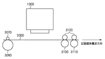
また、最近では、デジタルカメラで撮影した画像を、銀塩写真と同様な品位で出力することへの要求も高まっている。しかしながら、記録媒体の先端部或いは後端部においては、記録装置の構成が原因で、記録媒体の搬送精度が低下し、記録品質が低下する傾向にある。記録品質が低下する主な原因は、記録ヘッドの前後で記録媒体を支えてこれを搬送する複数のローラの一部から、記録媒体が外れてしまう状況が生じることである。ここで、図7乃至図9を参照して、インクジェット方式の記録装置の構成、及び記録品質が低下する原因について説明する。 Recently, there has been an increasing demand for outputting images taken with a digital camera in the same quality as a silver halide photograph. However, at the front end portion or the rear end portion of the recording medium, due to the configuration of the recording device, the conveyance accuracy of the recording medium tends to decrease, and the recording quality tends to decrease. The main cause of the deterioration of the recording quality is that the recording medium comes off from some of a plurality of rollers that support and convey the recording medium before and after the recording head. Here, with reference to FIG. 7 to FIG. 9, the configuration of the ink jet recording apparatus and the cause of the deterioration of the recording quality will be described.
図7は、インクジェット方式の記録装置によって記録媒体の中央部分に記録している時の、記録ヘッド、記録媒体、及び記録媒体を搬送する搬送機構を模式的に示す図である。図7において、搬送方向上流側にある搬送ローラ3060及び下流側にある2つの排紙ローラ3100,3110は、それぞれ、ピンチローラ3070及び2つの拍車3120,3120と協働する。即ち、これらのローラは3組のニップ部を形成し、記録媒体2000を挟持して搬送する。
FIG. 7 is a diagram schematically illustrating a recording head, a recording medium, and a transport mechanism that transports the recording medium when recording is performed on the central portion of the recording medium by an ink jet recording apparatus. In FIG. 7, a
記録ヘッドカートリッジ1000は、インクを吐出するための複数の記録素子が図7の搬送方向と平行な方向に所定のピッチで配列されている記録ヘッドを有している。記録ヘッドカートリッジ1000は、図7の紙面に垂直な方向に移動走査しながら各記録素子よりインクを吐出し、搬送ローラ3060と排紙ローラ3100との間に位置している記録媒体2000の領域に対して、画像を形成する。このような記録ヘッドカートリッジ1000による記録走査と、3つのローラ対による記録媒体2000の搬送動作とを交互に繰り返すことにより、記録媒体2000に順次画像が形成されていく。
The
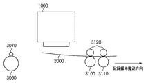
図8は、図7の状態から更に記録が進み、記録媒体2000の後端部近傍に対して記録を行っている状態を示す図である。記録媒体2000は、搬送ローラ3060から既に外れており、排紙ローラ3100,3110のみによって搬送されている。
FIG. 8 is a diagram showing a state in which recording further proceeds from the state of FIG. 7 and recording is performed on the vicinity of the rear end portion of the
一般に、搬送ローラ3060と排紙ローラ3100,3110とでは、その主な役割の違いから、ローラ径や搬送精度に若干の差が存在することが多い。搬送ローラ3060については、記録走査毎に、記録媒体を記録ヘッドに対する適切な位置に位置決めすることが主な役割である。よって、搬送ローラ3060は、充分に大きいローラ径を有し、比較的高い精度で搬送動作を行うことができる。これに対し、排紙ローラ3100,3110は、記録後の記録媒体を確実に排出することが主な役割となっている。よって、排紙ローラ3100,3110は、搬送ローラ3060に比べて、ローラ径が小さく、記録媒体の搬送精度も劣っていることが多い。従って、記録媒体2000の後端部が搬送ローラ3060から外れた時点から、記録媒体2000の最後端部の記録が終了するまでの領域に対しては、それ以前の領域に比べて、搬送精度が低下した状況で画像が形成される。この際に、搬送量が不十分な場合には隣接する記録走査間の画像形成部分が重なり合うことで所謂「黒スジ」が発生し、反対に、搬送量が多すぎる場合には記録走査間の画像形成部分が離れてしまうことで所謂「白スジ」が発生する場合がある。黒スジや白スジの発生により、記録された画像の品質が低下する。
In general, there are often slight differences in roller diameter and conveyance accuracy between the
また、記録媒体2000の両端部が保持されていないことに起因する記録品質の低下も発生する。記録媒体2000の後端部が搬送ローラ3060から外れると、記録ヘッドと記録媒体との距離(以下、「紙間距離」と呼ぶ)は少なからず変動し、その後も不安定な状態となる。記録ヘッドカートリッジ1000は、前後のローラによって維持される所定の紙間距離に対応したタイミングでインクを吐出しながら記録走査を行う。そして、適切なタイミングで吐出されたインクが記録媒体上でドットとなり、適切なピッチで配列されることによって画像が形成される。よって、記録の最中に紙間距離が変化したり、記録幅内(1回の記録走査)での紙間距離の変動が大きかったりすると、記録媒体におけるドットの位置が不適切に変動し、白スジや黒スジ、或いはザラツキ感などが発生する。
Further, the recording quality is deteriorated due to the fact that both ends of the
このような紙間距離の問題は、記録媒体2000の後端部のみならず、先端部を記録する場合にも同様に発生する。
Such a problem of the inter-paper distance similarly occurs when recording not only the rear end portion of the
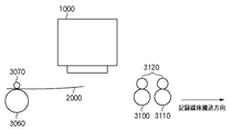
図9は、記録媒体2000の先端部近傍に対して記録を行っている状態を示す図である。この状態では、記録媒体2000は上流側の搬送ローラ3060及びピンチローラ3070のみによって保持され、搬送されている。即ち、先端部の記録が行われる場合、記録媒体2000の搬送には排紙ローラ3100,3110は関与していない。よって、図8で説明した後端部近傍を記録する状態に比べれば、高い精度で搬送がなされていると言い得る。しかし、記録媒体2000の先端が保持されていないことによる紙間距離の問題は、図8の状態と同様に生じる。即ち、記録媒体におけるドットの位置精度は、記録媒体2000の中央部の記録時(図7の状態)に比べて不安定となる。
FIG. 9 is a diagram illustrating a state where recording is performed on the vicinity of the front end portion of the
上記の問題に鑑み、記録媒体の先端部及び後端部において特別な記録方法を採用することにより、記録媒体の先端部及び後端部における記録品質の低下を抑制するインクジェット記録装置が提案されている。例えば、特に画像品位を重視するシリアル型の記録装置においては、次のような対処がなされている。 In view of the above problems, there has been proposed an ink jet recording apparatus that suppresses a decrease in recording quality at the front end portion and the rear end portion of the recording medium by adopting a special recording method at the front end portion and the rear end portion of the recording medium. Yes. For example, the following measures are taken in a serial type recording apparatus in which image quality is particularly important.
即ち、先後端部の記録に際しては、記録ヘッドの記録幅(即ち、実際にインクを吐出する記録素子の数)を狭め、これに合わせて記録媒体の搬送量も低下させる。記録ヘッドの記録幅を狭くすることにより、1回の記録走査における紙間距離の変動を抑制することができる。この場合、特に後述するマルチパス記録を実施すれば、ザラツキに対しても効果が発揮される。また、搬送精度が低下した状況においても、記録媒体の搬送量を小さくすることにより、その搬送誤差を小さくすることができる。更に、隣接する記録走査間の画像形成部分のつなぎ部分のピッチが細かくなることとも相俟って、白スジや黒スジが目立たなくなるという効果もある。 That is, when recording the leading and trailing edges, the recording width of the recording head (that is, the number of recording elements that actually eject ink) is narrowed, and the conveyance amount of the recording medium is also reduced accordingly. By narrowing the recording width of the recording head, fluctuations in the distance between sheets in one recording scan can be suppressed. In this case, if multi-pass printing, which will be described later, is performed, the effect is also exhibited against roughness. Even in a situation where the conveyance accuracy is lowered, the conveyance error can be reduced by reducing the conveyance amount of the recording medium. Further, coupled with the fact that the pitch of the connecting portions of the image forming portions between adjacent recording scans becomes fine, there is an effect that white stripes and black stripes become inconspicuous.
また、記録素子の配列密度が記録密度よりも低い形態の記録ヘッドを用い、複数回の記録走査によって副走査方向の記録密度を補間しながら画像を完成させていくインターレース記録方法を採用するインクジェット記録装置においても、同様な措置が行われる。即ち、先後端部でのみ実際にインクを吐出する記録素子の数を抑制し、これに合わせて記録媒体の搬送量を調整する。 Also, an ink jet recording that employs an interlace recording method that uses a recording head in which the arrangement density of the recording elements is lower than the recording density and completes an image while interpolating the recording density in the sub-scanning direction by a plurality of recording scans. Similar measures are taken in the apparatus. That is, the number of recording elements that actually eject ink only at the front and rear ends is suppressed, and the conveyance amount of the recording medium is adjusted accordingly.
更に、特許文献1及び特許文献2には、記録媒体の先後端部に記録する場合には、記録ヘッドの記録幅を狭くすることに加えて、記録ヘッドのノズル配列範囲における使用領域を切り替える構成が開示されている。即ち、記録媒体の先端部に記録する場合には、ノズル配列範囲における搬送方向下流側に位置する一部の領域を用い、記録媒体の後端部に記録する場合には、搬送方向上流側に位置する一部の領域を用いる。このように記録媒体の先端部と後端部とで記録ヘッドのノズル配列範囲の使用領域をそれぞれ切り替えることにより、記録媒体の先後端部における白スジや黒スジの目立ちやすい面積をより小さく抑えることも可能となる。
上述したように、白スジや黒スジの目立ちやすい記録媒体の先後端部における記録の際には、記録ヘッドの記録幅を狭め、記録品質の低下を目立ちにくくする制御が知られている。しかしながら、これらの制御はいずれも記録ヘッドの記録幅を狭めるため、結果的に記録速度の低下を招いてしまう。 As described above, when recording is performed at the front and rear end portions of a recording medium in which white stripes and black stripes are conspicuous, control is known in which the recording width of the recording head is narrowed so that deterioration in recording quality is less noticeable. However, both of these controls narrow the recording width of the recording head, resulting in a decrease in recording speed.
本発明はこのような状況に鑑みてなされたものである。本発明は、インクジェットプリンタ等の記録装置(印刷装置)により記録媒体の先後端部に画像を記録(印刷)する際に、記録速度の低下を抑制しつつ、画質の劣化の顕在化を抑制する技術を提供することを目的とする。 The present invention has been made in view of such a situation. In the present invention, when an image is recorded (printed) on the front and rear end portions of a recording medium by a recording device (printing device) such as an ink jet printer, the deterioration of image quality is suppressed while suppressing a decrease in recording speed. The purpose is to provide technology.
上記課題を解決するために、第1の本発明は、記録媒体を挟持して搬送する搬送ローラと排紙ローラとを備え、複数種類の色材を用いて前記記録媒体に画像を印刷する印刷ユニットを前記搬送ローラと前記排紙ローラとの間に備える印刷装置のために、印刷対象の画像データを、第1モード又は前記第1モードよりも多くの容量の色材が使用される第2モードで色分解する色分解手段と、前記画像データにおいて、前記搬送ローラ又は前記排紙ローラの一方のみによって前記記録媒体が挟持された状態で印刷される画像に対応するデータの存在を判定する判定手段と、を備え、前記色分解手段は、前記判定手段で存在しないと判定された場合、前記第1モードで前記画像データを色分解し、前記判定手段で存在すると判定された場合、前記第2モードで前記画像データを色分解することを特徴とする画像処理装置を提供する。 In order to solve the above-described problem, the first aspect of the present invention includes a transport roller and a paper discharge roller that sandwich and transport a recording medium, and prints an image on the recording medium using a plurality of types of color materials. For a printing apparatus provided with a unit between the transport roller and the paper discharge roller, the image data to be printed is a second mode in which a color material having a larger capacity than the first mode or the first mode is used. A color separation unit that performs color separation in a mode, and a determination for determining the presence of data corresponding to an image to be printed in a state where the recording medium is sandwiched by only one of the conveyance roller or the discharge roller in the image data And the color separation means color-separates the image data in the first mode when it is determined that the determination means does not exist, and when the determination means determines that the image data exists. To provide an image processing apparatus characterized by color decomposing the image data in the mode.
また、第2の本発明は、記録媒体を挟持して搬送する搬送ローラと排紙ローラとを備え、複数種類の色材を用いて前記記録媒体に画像を印刷する印刷ユニットを前記搬送ローラと前記排紙ローラとの間に備える印刷装置のために、印刷対象の画像データを、第1モード又は前記第1モードよりも多くの容量の色材が使用される第2モードで色分解する色分解工程と、前記画像データにおいて、前記搬送ローラ又は前記排紙ローラの一方のみによって前記記録媒体が挟持された状態で印刷される画像に対応するデータの存在を判定する判定工程と、を備え、前記色分解工程では、前記判定工程で存在しないと判定された場合、前記第1モードで前記画像データを色分解し、前記判定工程で存在すると判定された場合、前記第2モードで前記画像データを色分解することを特徴とする画像処理方法を提供する。 According to a second aspect of the present invention, there is provided a conveyance roller and a discharge roller for nipping and conveying the recording medium, and a printing unit for printing an image on the recording medium using a plurality of types of color materials. A color for color separation of image data to be printed in the first mode or the second mode in which a color material having a larger capacity than the first mode is used for the printing apparatus provided between the paper discharge rollers. A separation step, and a determination step of determining presence of data corresponding to an image to be printed in a state where the recording medium is sandwiched by only one of the transport roller or the paper discharge roller in the image data, In the color separation process, when it is determined that the image data does not exist in the determination process, the image data is color-separated in the first mode, and when it is determined that the image data exists in the determination process, the image is processed in the second mode. To provide an image processing method characterized by color decomposing over data.
また、第3の本発明は、コンピュータを記録媒体を挟持して搬送する搬送ローラと排紙ローラとを備え、複数種類の色材を用いて前記記録媒体に画像を印刷する印刷ユニットを前記搬送ローラと前記排紙ローラとの間に備える印刷装置のために、印刷対象の画像データを、第1モード又は前記第1モードよりも多くの容量の色材が使用される第2モードで色分解する色分解手段、前記画像データにおいて、前記搬送ローラ又は前記排紙ローラの一方のみによって前記記録媒体が挟持された状態で印刷される画像に対応するデータの存在を判定する判定手段、として機能させるためのプログラムであって、前記色分解手段は、前記判定手段で存在しないと判定された場合、前記第1モードで前記画像データを色分解し、前記判定手段で存在すると判定された場合、前記第2モードで前記画像データを色分解することを特徴とするプログラムを提供する。 According to a third aspect of the present invention, there is provided a transport unit that transports a computer while sandwiching a recording medium and a paper discharge roller, and the transport unit that prints an image on the recording medium using a plurality of types of color materials. For the printing apparatus provided between the roller and the paper discharge roller, the image data to be printed is color-separated in the first mode or in the second mode in which a larger amount of color material is used than in the first mode. Functioning as color separation means for determining the presence of data corresponding to an image to be printed in a state where the recording medium is sandwiched by only one of the transport roller or the paper discharge roller in the image data. If the determination means determines that the color separation means does not exist, the color separation means color-separates the image data in the first mode and exists in the determination means. When it is determined to provide a program, characterized by color separation of the image data in the second mode.
なお、その他の本発明の特徴は、添付図面及び以下の発明を実施するための最良の形態における記載によって更に明らかになるものである。 Other features of the present invention will become more apparent from the accompanying drawings and the following description of the best mode for carrying out the invention.
以上の構成により、本発明によれば、インクジェットプリンタ等の記録装置(印刷装置)により記録媒体の先後端部に画像を記録(印刷)する際に、記録速度の低下を抑制しつつ、画質の劣化の顕在化を抑制することが可能となる。 With the above configuration, according to the present invention, when an image is recorded (printed) on the front and rear end portions of a recording medium by a recording device (printing device) such as an ink jet printer, image quality can be reduced while suppressing a decrease in recording speed. It becomes possible to suppress the manifestation of deterioration.
以下、添付図面を参照して、本発明の実施形態を説明する。以下で説明される個別の実施形態は、本発明の上位概念から下位概念までの種々の概念を理解するために役立つであろう。 Embodiments of the present invention will be described below with reference to the accompanying drawings. The individual embodiments described below will help to understand various concepts from the superordinate concept to the subordinate concept of the present invention.
なお、本発明の技術的範囲は、特許請求の範囲によって確定されるのであって、以下の個別の実施形態によって限定されるわけではない。また、実施形態の中で説明されている特徴の組み合わせすべてが、本発明に必須とは限らない。 The technical scope of the present invention is determined by the claims, and is not limited by the following individual embodiments. In addition, not all combinations of features described in the embodiments are essential to the present invention.
[第1の実施形態]
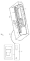
以下、本発明の画像処理装置をパーソナルコンピュータ(PC)に適用した実施形態について説明する。図1は、画像処理装置としてのPC14と、記録装置(印刷装置)としてのプリンタ13とを含む、印刷システム20を示す図である。本実施形態において、プリンタ13は、インクジェット方式のプリンタであるものとする。
[First Embodiment]
Hereinafter, an embodiment in which the image processing apparatus of the present invention is applied to a personal computer (PC) will be described. FIG. 1 is a diagram showing a
プリンタ13は、キャリッジ2を備え、キャリッジ2は、複数(例えば、5個)の記録ヘッドカートリッジ1A,1B,1C,1D,1Eを交換可能に搭載する。なお、複数の記録ヘッドカートリッジ1A〜1Eの全体又は任意の一つを指す場合、単に記録ヘッドカートリッジ1と呼ぶ。
The
記録ヘッドカートリッジ1は、それぞれ、上部にインクタンクを、下部に印刷ユニットとしての記録ヘッド(インク吐出部)を有しており、記録ヘッドとインクタンクを一体化した構造をしている。記録ヘッドカートリッジ1は、キャリッジ2に位置決めして交換可能に搭載されており、各記録ヘッドカートリッジ1のそれぞれには、記録ヘッドを駆動するための信号(駆動信号)などを受信するためのコネクタ(不図示)が設けられている。
Each of the
また、キャリッジ2には、このコネクタを通して各記録ヘッドカートリッジ1に駆動信号などを伝達するためのコネクタホルダ(電気接続部)が設けられている。そして、キャリッジ2上の各記録ヘッドカートリッジ1とプリンタ13本体の制御回路とは、信号パルス電流や温調用電流などを流すためのフレキシブルケーブルで接続されている。
Further, the
記録ヘッドカートリッジ1Aは、色材としてインクタンク内に黒(ブラック)(以下、「K」)の顔料インクを保持する。同様に、記録ヘッドカートリッジ1B,1C,1D,1Eはそれぞれ、シアン(以下、「C」)、マゼンタ(以下、「M」)、イエロー(以下、「Y」)、グレイ(以下、「G」)の染料インクを保持する。即ち、記録ヘッドカートリッジ1は、複数種類の色材を用いた記録を行う。記録ヘッドカートリッジ1の記録ヘッドの、記録媒体8と対向する面(図の例では下向きの吐出口面)には、インク滴を吐出するための吐出口が所定の配列を成して形成され、保持するインクを吐出するように構成されている。
The recording head cartridge 1A holds black (black) (hereinafter, “K”) pigment ink in an ink tank as a color material. Similarly, the print head cartridges 1B, 1C, 1D, and 1E are cyan (hereinafter “C”), magenta (hereinafter “M”), yellow (hereinafter “Y”), gray (hereinafter “G”), respectively. ) Dye ink. That is, the
キャリッジ2は、主走査方向に延在させてプリンタ13本体に設置されたガイドシャフト3に沿って往復移動可能に案内支持されている。そして、キャリッジ2は、主走査モータ4により、モータプーリ5、従動プーリ6、及びタイミングベルト7を介して駆動され、その位置及び移動を制御される。
The
用紙やプラスチックシート等の記録媒体8は、搬送ローラ9,10の対と排紙ローラ11,12の対との間で挟持され、これらのローラの回転により記録ヘッドカートリッジ1の吐出口面と対向する位置(記録部)を通して搬送(紙送り)される。なお、記録媒体8は、記録部において平坦な記録面を形成するように、その裏面をプラテン(不図示)により支持されている。また、キャリッジ2に搭載された記録ヘッドカートリッジ1は、それらの吐出口面がキャリッジ2から下方へ突出して2対のローラ間で記録媒体8と平行になるように保持されている。
A
なお、背景技術の欄で述べたように、記録媒体8の先端部の記録においては、搬送ローラ9,10の対のみによって記録媒体8が挟持される。同様に、記録媒体8の後端部の記録においては、排紙ローラ11,12の対のみによって記録媒体8が挟持される。従って、搬送ローラ9,10又は排紙ローラ11,12の一方のみによって挟持された状態で画像が印刷される領域では、記録ヘッドによって記録媒体8上に形成されるドット位置が不安定になる。そのため、2つのローラ対で挟持されて記録される中央領域に比べ画質が劣化しやすい。
Note that, as described in the section of the background art, in recording at the leading end portion of the
以上説明した構成を持つプリンタ13は、ケーブル15を介してPC14に接続され、PC14内にインストールされたドライバソフトウェアによって制御される。
The
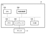
図2は、PC14の構成を示すブロック図である。PC14は、CPU202と、メモリ203と、外部記憶装置204と、入力部205と、プリンタ13と接続するためのインタフェース206とを備える。
FIG. 2 is a block diagram showing the configuration of the
CPU202は、メモリ203に格納されたプログラム(ドライバソフトウェア)を実行することにより、後述する色処理(色補正、色分解など)、量子化処理などの各種の画像処理を実行する。このプログラムは、外部記憶装置204に記憶されていてもよいし、或いはPC14の外部から供給されてもよい。PC14は、インタフェース206を介してプリンタ13と接続されており、画像処理を施した画像データをプリンタ13に送信して記録を行わせる。
The
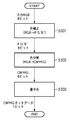
図3は、PC14のCPU202が実行する画像処理の流れを示すフローチャートである。印刷対象の画像データは、通常、PC14に適した表色系であるRGB表色系によって表現される。以下では説明のために、印刷対象の画像データはRGB各8ビットで表現されるものとする。なお、印刷対象の画像データは、例えば外部記憶装置204に格納されており、入力部205を介したユーザからの印刷指示に応じて、CPU202によってメモリ203へロードされる。
FIG. 3 is a flowchart showing a flow of image processing executed by the
S301で、CPU202は、印刷対象の画像データ(RGB8ビットデータ)に対し、画像の用途(写真やグラフィック等)に応じた色補正を施す(色補正後のデータを、「R’G’B’8ビットデータ」と呼ぶ)。色補正のためには、三次元ルックアップテーブル(3D−LUT)を用いることができる。
In step S <b> 301, the
S302で、CPU202は、R’G’B’8ビットデータを、記録ヘッドカートリッジ1が保持するインクの色に対応する画像データに変換する処理(色分解処理)を行う。色分解処理の結果、本実施形態では、CMYKG各8ビットで表現される画像データが生成される。色分解のためにも、3D−LUTを用いることができる。S302における処理の詳細は、図4を参照して後述する。
In step S <b> 302, the
S303で、CPU202は、CMYKG8ビットデータを、プリンタ13に適応した所定の記録ビット数(本実施形態では1ビット)のデータに変換する処理(量子化処理)を行う。量子化方法としては、任意の知られている技術(例えば、誤差拡散法やディザ法)を用いることができる。
In step S303, the
プリンタ13は、以上の処理が施された画像データをケーブル15を介して受信し、画像の記録を行うことができる。
The
図4は、図3のS302における色分解処理の詳細を示すフローチャートである。 FIG. 4 is a flowchart showing details of the color separation processing in S302 of FIG.
S401で、CPU202は、用紙サイズや印刷位置(例えば、「紙面中央」、「紙面上部」等)等の印刷情報に基づき、印刷対象の画像データの記録媒体8上でのレイアウトを把握する。印刷情報は、例えば、ドライバソフトウェアがPC14のディスプレイ上に表示するユーザインタフェースを介して、ユーザによって指示される。
In step S401, the
S402で、CPU202は、S401で把握したレイアウトに基づき、搬送ローラ9,10又は排紙ローラ11,12の2つのローラ対のうち、一方の対のみによって記録媒体8が挟持された状態で印刷される画像が存在するか否かを判定する。このとき、CPU202は、2つのローラ対のうち一方の対のみによって記録媒体8が挟持された状態で画像が印刷される記録媒体8上の領域を示す、ローラ保持領域データを参照する。なお、ローラ保持領域データは、例えば、外部記憶装置204に格納されている。
In step S402, the
S401及びS402における処理は、換言すれば、印刷対象の画像データにおいて、搬送ローラ又は排紙ローラの一方のみによって記録媒体8が挟持された状態で印刷される画像に対応するデータの存在を判定する処理である。そのようなデータが存在する場合、S404に進み、存在しない場合、S403に進む。
In other words, the processing in S401 and S402 determines the presence of data corresponding to an image to be printed in a state where the
S403では、CPU202は、印刷対象の画像データを第1モードで色分解する。一方、S404では、CPU202は、印刷対象の画像データを第2モードで色分解する。第1モード及び第2モードの詳細は図5及び図6を参照して後述するが、簡単に説明すると、プリンタ13が第2モードで色分解された画像データを印刷する際に使用(吐出)するインクの容量は、第1モードの場合よりも多い。
In step S403, the
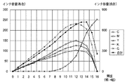
図5は、第1モードでの色分解のための3D−LUTの概要を示す図である。図6は、第2モードでの色分解のための3D−LUTの概要を示す図である。説明を簡単にするために、図5及び図6では、無彩色軸、即ち白から黒にかけてのグレイの階調のみを示すが、有彩色の全領域に対しても以下の説明が同様に当てはまる。また、横軸は色分解前の画像データの輝度を16階調で示し、数値が小さいほど明るく、数値が大きいほど暗いデータを示す。 FIG. 5 is a diagram illustrating an outline of a 3D-LUT for color separation in the first mode. FIG. 6 is a diagram illustrating an outline of a 3D-LUT for color separation in the second mode. For ease of explanation, FIGS. 5 and 6 show only the achromatic axis, that is, the gray gradation from white to black, but the following explanation applies to the entire chromatic color region as well. . The horizontal axis indicates the luminance of the image data before color separation in 16 gradations. The smaller the numerical value, the brighter the data, and the larger the numerical value, the darker the data.
第1モード(図5)では、印刷対象の画像データは、CMYKの4色のみに分解される。一方、第2モード(図6)では、印刷対象の画像データは、CMYKGの5色に分解される。右側の縦軸で示される合計インク容量は、ほぼ全域で図6の方が多い。これは前述の通り、有彩色の領域においても同様である。 In the first mode (FIG. 5), the image data to be printed is decomposed into only four colors of CMYK. On the other hand, in the second mode (FIG. 6), the image data to be printed is separated into five colors of CMYKG. The total ink capacity indicated by the vertical axis on the right side is larger in FIG. As described above, the same applies to the chromatic color region.
合計インク容量が多いということは、記録媒体8の所定領域に付与されるインクの総量が多いということである。その結果、記録媒体8の表面において、インクの被覆率が高くなる。反対に、合計インク容量が少ないということは、記録媒体8の所定領域に付与されるインクの総量も少ないということである。その結果、インクの被覆率も低くなる。
A large total ink capacity means that the total amount of ink applied to a predetermined area of the
インクの被覆率が高い場合、着弾ずれ(図7乃至図9を参照して説明した、ドットの位置の不適切な変動)が発生しても、画質の劣化はそれほど顕在化しない。しかし、インクの被覆率が低い状態で着弾ずれが発生すると、画質の劣化が顕在化する。これは、被覆率が低い状態では高い状態に比べて記録媒体8そのものの色が多く(大きい面積で)見える確率が高くなるため、着弾ずれに起因する記録媒体8そのものの色の見え方の変動が激しくなるからである。
When the ink coverage is high, even if landing deviation (inappropriate fluctuation of the dot position described with reference to FIGS. 7 to 9) occurs, the deterioration of the image quality is not so obvious. However, if a landing deviation occurs in a state where the ink coverage is low, degradation of image quality becomes obvious. This is because the probability that the color of the
従って、搬送ローラ又は排紙ローラの一方のみによって挟持された状態で記録される領域が存在する場合に、使用されるインク容量が多い第2モードで色分解すれば、記録媒体8の先端部及び後端部における画質の劣化の顕在化を軽減することができる。
Therefore, if there is an area to be recorded while being sandwiched by only one of the transport roller and the paper discharge roller, if color separation is performed in the second mode in which the amount of ink used is large, the leading edge of the
一方、搬送ローラ又は排紙ローラの一方のみによって挟持された状態で記録される領域が存在しない場合は、使用されるインク容量が少ない第1モードで色分解すれば、無駄なインクの消費を抑制することができる。 On the other hand, if there is no area to be recorded in a state where it is nipped only by one of the transport roller or the discharge roller, it is possible to suppress wasteful ink consumption by performing color separation in the first mode in which the amount of ink used is small. can do.
また、本実施形態では、色分解モードの切り替えによってインク使用量の増減のみを行い、その他の条件(記録パス数、ヘッド記録幅など)は変更しないため、背景技術において説明したような記録速度の低下も抑制される。 In this embodiment, the ink usage amount is only increased or decreased by switching the color separation mode, and other conditions (number of recording passes, head recording width, etc.) are not changed. The decrease is also suppressed.
<変形例1>
上記の実施形態においては、搬送ローラ又は排紙ローラの一方のみによって記録媒体8が挟持された状態で印刷される画像が存在する場合、画像データ全体が第2モードで色分解された。しかし、そのような画像が存在する場合であっても、搬送ローラ及び排紙ローラの両方によって記録媒体8が挟持された状態で印刷される画像に対応するデータについては、第1モードで色分解してもよい。このように、印刷領域に応じて色分解モードを切り替えることにより、記録媒体8の中央部に対するインク使用量を減少させることができる。
<
In the above embodiment, when there is an image to be printed in a state where the
<変形例2>
上記の実施形態においては、CMYK以外のインクとしてグレイのインクを用いたが、CMYと基本的に色相が同じで、濃度が低い少なくとも1種類の色材、即ち、淡シアン、淡マゼンタ等のインクを用いてもよい。即ち、PC14は、第2モードにおいては、第1モードで使用される種類の色材に加えて、第1モードで使用される種類の色材のいずれかと色相が同じで濃度が低い少なくとも1種類の色材が使用されるように画像データを色分解することができる。
<
In the above embodiment, gray ink is used as ink other than CMYK. However, at least one kind of color material having the same hue and low density as CMY, that is, light cyan, light magenta, or the like is used. May be used. That is, in the second mode, the
<変形例3>
上記の実施形態においては、プリンタ13はインクジェット方式のプリンタであるものとした。しかし、これ以外の方式のプリンタ、例えば電子写真方式のプリンタに対しても、上記の実施形態を適用することができる。この場合、転写ドラムが印刷ユニットに相当し、トナーが色材に相当する。
<
In the above embodiment, the
<変形例4>
上記の実施形態においては、PC14がドライバソフトウェアを実行することにより、本発明の画像処理装置が構成されるものとした。しかしながら、本発明の画像処理装置は、プリンタ13に実装されてもよい。この場合、プリンタ13が、図3及び図4を参照して説明した色分解処理を実行する。従って、このような構成を備えるプリンタ13(印刷装置)も、本発明の範囲に含まれる。
<
In the above embodiment, the image processing apparatus of the present invention is configured by the
また、図3及び図4を参照して説明した画像処理の一部が、プリンタ13よって実行されてもよい。
Further, a part of the image processing described with reference to FIGS. 3 and 4 may be executed by the
また、上記の実施形態においては、搬送ローラ9,10及び排紙ローラ11,12はそれぞれ1対ずつ存在するものとしたが、これに限るものではなく、例えば図7と同様、排紙ローラ11,12が2対存在してもよい。
Further, in the above-described embodiment, a pair of the
以上説明したように、本実施形態によれば、PC14は、印刷対象の画像データにおいて、搬送ローラ又は排紙ローラの一方のみによって記録媒体8が挟持された状態で印刷される画像に対応するデータの存在を判定する。そのようなデータが存在しない場合、PC14は画像データを第1モードで色分解し、存在する場合、第1モードよりも多くの容量の色材が使用される第2モードで色分解する。
As described above, according to the present embodiment, the
これにより、インクジェットプリンタ等の記録装置(印刷装置)により記録媒体の先後端部に画像を記録(印刷)する際に、記録速度の低下を抑制しつつ、画質の劣化の顕在化を抑制することが可能となる。 As a result, when an image is recorded (printed) on the front and rear end portions of the recording medium by a recording device (printing device) such as an ink jet printer, the deterioration of the image quality is suppressed while suppressing a decrease in recording speed. Is possible.
<変形例5>
以上の例では、第1の記録モードと第2の記録モードとで、使用するインクの構成を変更していたが、同一インク構成でインク使用量の異なる2つのモードを設定しても良い。
<
In the above example, the configuration of the ink to be used is changed between the first recording mode and the second recording mode. However, two modes with different ink usage may be set with the same ink configuration.
この変形例を図10と図11とを用いて説明する。図10は、第1モードでの色分解のための3D−LUTの概要を示す図である。図11は、第2モードでの色分解のための3D−LUTの概要を示す図である。図5及び図6と同様、説明を簡単にするために、図10及び図11では、無彩色軸、即ち白から黒にかけてのグレイの階調のみを示すが、有彩色の全領域に対しても以下の説明が同様に当てはまる。また、横軸は色分解前の画像データの輝度を16階調で示し、数値が小さいほど明るく、数値が大きいほど暗いデータを示す。 This modification will be described with reference to FIGS. FIG. 10 is a diagram illustrating an outline of a 3D-LUT for color separation in the first mode. FIG. 11 is a diagram illustrating an outline of a 3D-LUT for color separation in the second mode. As in FIGS. 5 and 6, for the sake of simplicity, FIGS. 10 and 11 show only the achromatic color axis, that is, the gray gradation from white to black, but for the entire chromatic color region. The following explanation applies as well. The horizontal axis indicates the luminance of the image data before color separation in 16 gradations. The smaller the numerical value, the brighter the data, and the larger the numerical value, the darker the data.
第1モード(図10)、第2モード(図11)共に、印刷対象の画像データは、CMYKの4色のみに分解される。しかし、Kのデータが第2モード(図11)に比べ第1モード(図10)ではより明るい階調から入っており、また階調全体にわたって使用量が多くなっている。CMYに比べ濃度の濃いKの量が少ない分、第2モード(図11)では、第1(図10)モードに比べてCMYの使用量が多くなる。その結果、右側の縦軸で示される合計インク容量は、ほぼ全域で第2モード(図11)の方が多い。これは前述の通り、有彩色の領域においても同様である。このようにして、同一のインク構成でも、色分解のテーブルを切り替えることによってインク使用量の異なる2つのモードを設定できる。 In both the first mode (FIG. 10) and the second mode (FIG. 11), the image data to be printed is decomposed into only four colors of CMYK. However, in the first mode (FIG. 10), K data enters from a brighter gradation than in the second mode (FIG. 11), and the amount of use is increased over the entire gradation. Since the amount of K having a higher density than CMY is small, the amount of CMY used in the second mode (FIG. 11) is larger than that in the first (FIG. 10) mode. As a result, the total ink capacity indicated by the vertical axis on the right side is larger in the second mode (FIG. 11) in almost the entire region. As described above, the same applies to the chromatic color region. In this way, even with the same ink configuration, two modes with different ink usage can be set by switching the color separation table.
[その他の実施形態]
上述した各実施形態の機能を実現するためには、各機能を具現化したソフトウェアのプログラムコードを記録した記録媒体をシステム或は装置に提供してもよい。そして、そのシステム或は装置のコンピュータ(又はCPUやMPU)が記録媒体に格納されたプログラムコードを読み出し実行することによって、上述した各実施形態の機能が実現される。この場合、記録媒体から読み出されたプログラムコード自体が上述した各実施形態の機能を実現することになり、そのプログラムコードを記録した記録媒体は本発明を構成することになる。このようなプログラムコードを供給するための記録媒体としては、例えば、フロッピィ(登録商標)ディスク、ハードディスク、光ディスク、光磁気ディスクなどを用いることができる。或いは、CD−ROM、CD−R、磁気テープ、不揮発性のメモリカード、ROMなどを用いることもできる。
[Other Embodiments]
In order to realize the functions of the above-described embodiments, a recording medium in which a program code of software embodying each function is recorded may be provided to the system or apparatus. The functions of the above-described embodiments are realized by the computer (or CPU or MPU) of the system or apparatus reading and executing the program code stored in the recording medium. In this case, the program code itself read from the recording medium realizes the functions of the above-described embodiments, and the recording medium on which the program code is recorded constitutes the present invention. As a recording medium for supplying such a program code, for example, a floppy (registered trademark) disk, a hard disk, an optical disk, a magneto-optical disk, or the like can be used. Alternatively, a CD-ROM, CD-R, magnetic tape, nonvolatile memory card, ROM, or the like can be used.
また、上述した各実施形態の機能を実現するための構成は、コンピュータが読み出したプログラムコードを実行することだけには限られない。そのプログラムコードの指示に基づき、コンピュータ上で稼動しているOS(オペレーティングシステム)などが実際の処理の一部又は全部を行い、その処理によって上述した各実施形態の機能が実現される場合も含まれている。 The configuration for realizing the functions of the above-described embodiments is not limited to executing the program code read by the computer. Including the case where the OS (operating system) running on the computer performs part or all of the actual processing based on the instruction of the program code, and the functions of the above-described embodiments are realized by the processing. It is.
更に、記録媒体から読み出されたプログラムコードが、コンピュータに挿入された機能拡張ボードやコンピュータに接続された機能拡張ユニットに備わるメモリに書きこまれてもよい。その後、そのプログラムコードの指示に基づき、その機能拡張ボードや機能拡張ユニットに備わるCPUなどが実際の処理の一部又は全部を行い、その処理によって上述した各実施形態の機能が実現される場合も含むものである。 Further, the program code read from the recording medium may be written in a memory provided in a function expansion board inserted into the computer or a function expansion unit connected to the computer. Thereafter, the CPU of the function expansion board or function expansion unit performs part or all of the actual processing based on the instruction of the program code, and the functions of the above-described embodiments may be realized by the processing. Is included.
1A〜1E 記録ヘッドカートリッジ
2 キャリッジ
3 ガイドシャフト
4 主走査モータ
5 モータプーリ
6 従動プーリ
7 タイミングベルト
8 記録媒体
9,10 搬送ローラ
11,12 排紙ローラ
13 プリンタ
14 パーソナルコンピュータ(PC)
15 ケーブル
1A to 1E
15 cable
Claims (9)
前記画像データにおいて、前記搬送ローラ又は前記排紙ローラの一方のみによって前記記録媒体が挟持された状態で印刷される画像に対応するデータの存在を判定する判定手段と、
を備え、
前記色分解手段は、前記判定手段で存在しないと判定された場合、前記第1モードで前記画像データを色分解し、前記判定手段で存在すると判定された場合、前記第2モードで前記画像データを色分解する
ことを特徴とする画像処理装置。 A conveyance roller and a discharge roller for nipping and conveying the recording medium are provided, and a printing unit for printing an image on the recording medium using a plurality of types of color materials is provided between the conveyance roller and the discharge roller. Color separation means for color-separating image data to be printed in a first mode or a second mode in which a color material having a larger capacity than the first mode is used for a printing apparatus;
Determining means for determining presence of data corresponding to an image to be printed in a state where the recording medium is sandwiched by only one of the transport roller or the discharge roller in the image data;
With
The color separation means color-separates the image data in the first mode when it is determined that the determination means does not exist, and the image data in the second mode when it is determined that the determination means exists. An image processing apparatus characterized in that color separation is performed.
前記色分解手段は、前記第1モードでは前記グレイの色材が使用されず、前記第2モードでは前記グレイの色材が使用されるように、前記画像データを色分解する
ことを特徴とする請求項1又は2に記載の画像処理装置。 The plurality of types of color materials include a black color material and a gray color material,
The color separation means color-separates the image data so that the gray color material is not used in the first mode and the gray color material is used in the second mode. The image processing apparatus according to claim 1.
前記印刷ユニットは記録ヘッドである
ことを特徴とする請求項1乃至4のいずれか1項に記載の画像処理装置。 The printing apparatus is an ink jet printer,
The image processing apparatus according to claim 1, wherein the printing unit is a recording head.
前記印刷ユニットは転写ドラムである
ことを特徴とする請求項1乃至4のいずれか1項に記載の画像処理装置。 The printing apparatus is an electrophotographic printer,
The image processing apparatus according to claim 1, wherein the printing unit is a transfer drum.
前記画像データにおいて、前記搬送ローラ又は前記排紙ローラの一方のみによって前記記録媒体が挟持された状態で印刷される画像に対応するデータの存在を判定する判定工程と、
を備え、
前記色分解工程では、前記判定工程で存在しないと判定された場合、前記第1モードで前記画像データを色分解し、前記判定工程で存在すると判定された場合、前記第2モードで前記画像データを色分解する
ことを特徴とする画像処理方法。 A conveyance roller and a discharge roller for nipping and conveying the recording medium are provided, and a printing unit for printing an image on the recording medium using a plurality of types of color materials is provided between the conveyance roller and the discharge roller. A color separation process for color-separating image data to be printed in a first mode or a second mode in which a color material having a larger capacity than the first mode is used for a printing apparatus;
A determination step of determining presence of data corresponding to an image to be printed in a state where the recording medium is sandwiched by only one of the transport roller or the discharge roller in the image data;
With
In the color separation step, if it is determined that the image data does not exist in the determination step, the image data is color-separated in the first mode, and if it is determined that the image data exists in the determination step, the image data in the second mode. An image processing method characterized by separating colors.
記録媒体を挟持して搬送する搬送ローラと排紙ローラとを備え、複数種類の色材を用いて前記記録媒体に画像を印刷する印刷ユニットを前記搬送ローラと前記排紙ローラとの間に備える印刷装置のために、印刷対象の画像データを、第1モード又は前記第1モードよりも多くの容量の色材が使用される第2モードで色分解する色分解手段、
前記画像データにおいて、前記搬送ローラ又は前記排紙ローラの一方のみによって前記記録媒体が挟持された状態で印刷される画像に対応するデータの存在を判定する判定手段、
として機能させるためのプログラムであって、
前記色分解手段は、前記判定手段で存在しないと判定された場合、前記第1モードで前記画像データを色分解し、前記判定手段で存在すると判定された場合、前記第2モードで前記画像データを色分解する
ことを特徴とするプログラム。 A printing unit for printing an image on the recording medium using a plurality of types of color materials is provided between the carrying roller and the paper discharge roller. A color separation means for color-separating image data to be printed in a first mode or a second mode in which a color material having a capacity larger than that in the first mode is used.
Determining means for determining presence of data corresponding to an image to be printed in a state in which the recording medium is sandwiched by only one of the transport roller or the discharge roller in the image data;
Is a program for functioning as
The color separation means color-separates the image data in the first mode when it is determined that the determination means does not exist, and the image data in the second mode when it is determined that the determination means exists. A program characterized by color separation.
Priority Applications (1)
| Application Number | Priority Date | Filing Date | Title |
|---|---|---|---|
| JP2007335061A JP2009154392A (en) | 2007-12-26 | 2007-12-26 | Image processing apparatus, printing apparatus, image processing method, and program |
Applications Claiming Priority (1)
| Application Number | Priority Date | Filing Date | Title |
|---|---|---|---|
| JP2007335061A JP2009154392A (en) | 2007-12-26 | 2007-12-26 | Image processing apparatus, printing apparatus, image processing method, and program |
Publications (1)
| Publication Number | Publication Date |
|---|---|
| JP2009154392A true JP2009154392A (en) | 2009-07-16 |
Family
ID=40958926
Family Applications (1)
| Application Number | Title | Priority Date | Filing Date |
|---|---|---|---|
| JP2007335061A Withdrawn JP2009154392A (en) | 2007-12-26 | 2007-12-26 | Image processing apparatus, printing apparatus, image processing method, and program |
Country Status (1)
| Country | Link |
|---|---|
| JP (1) | JP2009154392A (en) |
-
2007
- 2007-12-26 JP JP2007335061A patent/JP2009154392A/en not_active Withdrawn
Similar Documents
| Publication | Publication Date | Title |
|---|---|---|
| JP4822712B2 (en) | Image forming apparatus, image processing method, and program | |
| JP4909321B2 (en) | Image processing method, program, image processing apparatus, image forming apparatus, and image forming system | |
| US7600842B2 (en) | Image reproducing and forming apparatus, printer driver and data processing apparatus | |
| JP5560681B2 (en) | Recording method, recorded matter, recording apparatus, and operation control program | |
| US8011756B2 (en) | Imaging method and inkjet recording apparatus | |
| JP2010089487A (en) | Image processing device, image processing method, program, recording medium, printing system and image forming apparatus | |
| JP2007137049A (en) | Image processing method, program, image processing apparatus, image forming apparatus, and image forming system | |
| US20070242096A1 (en) | Ink-jet recording device, image-processing device, and image processing method | |
| JP2006173929A (en) | Image processing method, program, image processing apparatus, and image forming apparatus | |
| CN100434274C (en) | Recording device and recording method | |
| JP4765455B2 (en) | Image forming apparatus, image forming method, data generating apparatus, data generating method, and program | |
| US9160893B2 (en) | Image recording system and image recording method | |
| JP3886051B2 (en) | Image forming apparatus, printer driver, and data processing apparatus | |
| JP2005032258A (en) | Printing method and printer using non-uniform resolution per raster | |
| US9862217B2 (en) | Printing apparatus | |
| JP2007185941A (en) | Ink jet recording apparatus and recording method | |
| JP2009154392A (en) | Image processing apparatus, printing apparatus, image processing method, and program | |
| JP7387307B2 (en) | Recording device, recording method, and program | |
| US8274695B2 (en) | Image processing apparatus and droplet ejection apparatus | |
| JP2017024347A (en) | Print control apparatus and print control method | |
| JP2006346931A (en) | Image forming apparatus, method of forming image, image processor, and program | |
| JP2003320647A (en) | Ink jet recorder | |
| JP2020044678A (en) | Control device, printer, and computer program | |
| JP2010068497A (en) | Image processor, image processing method, program, recording medium, printing system, and image forming apparatus | |
| JP2006326882A (en) | Inkjet recording device |
Legal Events
| Date | Code | Title | Description |
|---|---|---|---|
| A300 | Withdrawal of application because of no request for examination |
Free format text: JAPANESE INTERMEDIATE CODE: A300 Effective date: 20110301 |