JP2009153143A - Electronic instrument - Google Patents
Electronic instrument Download PDFInfo
- Publication number
- JP2009153143A JP2009153143A JP2008329559A JP2008329559A JP2009153143A JP 2009153143 A JP2009153143 A JP 2009153143A JP 2008329559 A JP2008329559 A JP 2008329559A JP 2008329559 A JP2008329559 A JP 2008329559A JP 2009153143 A JP2009153143 A JP 2009153143A
- Authority
- JP
- Japan
- Prior art keywords
- moving image
- map
- image data
- unit
- display
- Prior art date
- Legal status (The legal status is an assumption and is not a legal conclusion. Google has not performed a legal analysis and makes no representation as to the accuracy of the status listed.)
- Granted
Links
Images


Landscapes
- Television Signal Processing For Recording (AREA)
- Two-Way Televisions, Distribution Of Moving Picture Or The Like (AREA)
- Mobile Radio Communication Systems (AREA)
- Telephone Function (AREA)
Abstract
Description
本発明は、電子機器に関し、特に時系列情報(例えば、動画像データ)の受信もしくは送信を行う電子機器、および、その処理方法ならびに当該方法をコンピュータに実行させるプログラムに関する。 The present invention relates to an electronic device, and more particularly to an electronic device that receives or transmits time-series information (for example, moving image data), a processing method thereof, and a program that causes a computer to execute the method.
従来より、GPS(Global Positioning System)を利用して現在の位置情報を取得し、その位置情報と地図情報とを対応させることにより地図上に現在の位置を表示する機能を有する装置が知られている。近年、このようなGPS機能を内蔵したディジタルカメラ等の撮像装置が提案されており、そのような撮像装置では画像を撮像すると同時に撮像位置における位置情報を取得し、その画像と位置情報とを関連付けて記録するようになっている。 Conventionally, there has been known an apparatus having a function of displaying current position on a map by acquiring current position information using GPS (Global Positioning System) and associating the position information with map information. Yes. In recent years, an imaging apparatus such as a digital camera incorporating such a GPS function has been proposed. In such an imaging apparatus, position information at an imaging position is acquired at the same time as capturing an image, and the image and the position information are associated with each other. To record.
また、撮像装置の単体で、位置情報に基づいて地図上にアイコンを表示し、アイコンが選択されるとそのアイコンにリンクした画像を表示する撮像装置が提案されている(例えば、特許文献1参照。)。これによりユーザは撮像された画像がどの地点で撮像されたかを容易に知ることが可能となる。
上述の従来技術では、静止画と位置情報とを関連付けることにより、位置情報に基づいて地図上にアイコンを表示して、そのアイコンにリンクした画像を表示している。これに対し、動画像のような時系列情報の場合にはその時系列情報に含まれる内容によって位置情報が変動する可能性があるため、その時系列情報に含まれる内容のそれぞれについて位置情報を把握する必要がある。 In the above-described prior art, by associating a still image with position information, an icon is displayed on a map based on the position information, and an image linked to the icon is displayed. On the other hand, in the case of time-series information such as a moving image, the position information may vary depending on the contents included in the time-series information, so the position information is grasped for each of the contents included in the time-series information. There is a need.
特に、カメラ付携帯電話や携帯端末などのように他の機器との間で通信を行いながら移動する電子機器においては、時系列情報に対する位置情報を適切に表示することが有用である。 In particular, in an electronic device that moves while communicating with another device such as a mobile phone with a camera or a mobile terminal, it is useful to appropriately display position information with respect to time-series information.
そこで、本発明は、時系列情報を送受信する電子機器において時系列情報に対する位置情報を適切に表示することを目的とする。 Accordingly, an object of the present invention is to appropriately display position information for time series information in an electronic device that transmits and receives time series information.
本発明は、上記課題を解決するためになされたものであり、その第1の側面は、動画像データと上記動画像データが撮影された位置情報とを保持する動画像データ保持部と、上記動画像データの撮影位置を示す地図データが保持される地図保持部と、上記動画像データおよび上記地図データを表示するとともに、表示される上記地図データの領域および上記動画像データが撮影された移動範囲に基づいて、上記動画像データの撮影された道筋を示す表示を行うか否かを制御する表示制御部とを具備する電子機器およびその表示制御方法ならびにプログラムである。これにより、比較的広域な範囲を表す地図において、位置情報の履歴を視覚的に把握させるという作用をもたらす。 The present invention has been made to solve the above problems, and a first aspect thereof is a moving image data holding unit that holds moving image data and position information where the moving image data is captured; A map holding unit for storing map data indicating a shooting position of moving image data, the moving image data and the map data are displayed, and the area of the displayed map data and the movement in which the moving image data is shot An electronic apparatus including a display control unit that controls whether or not to display a captured route of the moving image data based on a range, and a display control method and program thereof. This brings about the effect of visually grasping the history of position information in a map representing a relatively wide range.
また、この第1の側面において、上記表示制御部は、表示される上記地図データの領域および上記動画像データが撮影された移動範囲に基づいて、上記地図上において上記動画像データの撮影された道筋を示す第1の表示態様および上記地図上において上記動画像データの撮影された道筋を示さない第2の表示態様を選択するようにしてもよい。この場合、第2の表示態様として円形表示を行ってもよい。 In the first aspect, the display control unit captures the moving image data on the map based on a region of the map data to be displayed and a moving range in which the moving image data is captured. You may make it select the 1st display mode which shows a path | route, and the 2nd display mode which does not show the path | route which image | photographed the said moving image data on the said map. In this case, circular display may be performed as the second display mode.
また、この第1の側面において、上記動画像データの撮影された道筋を示す表示において、上記道筋を示す情報のうちユーザにより選択された箇所に基づいて、当該箇所を撮影位置とした上記動画像データの再生を開始する再生部をさらに具備してもよい。 In the first aspect, in the display of the moving image data indicating the route taken, the moving image having the position as the shooting position based on the portion selected by the user from the information indicating the route. You may further provide the reproducing part which starts reproduction | regeneration of data.
本発明によれば、時系列情報を送受信する電子機器において時系列情報に対する位置情報を適切に表示するという優れた効果を奏し得る。 ADVANTAGE OF THE INVENTION According to this invention, the outstanding effect that the positional information with respect to time series information is appropriately displayed in the electronic device which transmits / receives time series information can be show | played.
次に本発明の実施の形態について図面を参照して詳細に説明する。 Next, embodiments of the present invention will be described in detail with reference to the drawings.
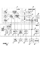
図1は、本発明の実施の形態における携帯機器100の構成例を示す図である。この携帯機器100は、カメラ部10と、記録再生処理部20と、制御部30とを備えている。また、この携帯機器100にはGPSモジュール50および通信装置60が接続されている。ここで、GPSモジュール50は、複数のGPS衛星からの電波を受信することによって現在位置の緯度および経度を算出する。また、通信装置60は、他の携帯機器と通信を行い、動画像データを含むデータの送受信を行う。これらGPSモジュール50および通信装置60は、それぞれ高周波(RF:Radio Frequency)部、中間周波数(IF:Intermediate Frequency)部、および、AD(Analog-Digital)変換部などを含むが、これら各部の一部または全部を互いに共用するように構成してもよい。
FIG. 1 is a diagram illustrating a configuration example of a
カメラ部10は、光学ブロック11と、カメラ制御部12と、信号変換器13と、撮像信号処理部14と、音声入力部15と、音声信号処理部16とを備える。光学ブロック11は、内部に、被写体を撮像するためのレンズ群、絞り調整機構、フォーカス調整機構、ズーム機構、シャッター機構、フラッシュ機構、および、手ぶれ補正機構などを備える。カメラ制御部12は、制御部30から制御信号を受けて、光学ブロック11に供給する制御信号を生成する。そして、生成した制御信号を光学ブロック11に供給して、ズーム制御、シャッター制御、および、露出制御などの制御を行う。
The
信号変換器13は、例えばCCD(Charge Coupled Device)などの撮像素子により構成され、その結像面に、光学ブロック11を通じた像が結像される。この信号変換器13は、シャッター操作に応じて制御部30から供給される画像取り込みタイミング信号を受けて、結像面に結像されている被写体像を撮像信号に変換し、撮像信号処理部14に供給する。
The
撮像信号処理部14は、制御部30からの制御信号に基づいて、撮像信号についてのガンマ補正やAGC(Auto Gain Control)などの処理を行うとともに、撮像信号をデジタル信号としての画像信号に変換する処理も行う。音声入力部15は、撮影時の被写体周辺の音声を収集する。この音声入力部15からの音声信号は音声信号処理部16に供給される。音声信号処理部16は、制御部30からの制御信号に基づいて、音声信号についての補正やAGCなどの処理を行うとともに、音声信号をデジタル信号に変換する処理も行う。
The imaging
記録再生処理部20は、符号化/復号回路21と、ディスクインターフェース23と、出力処理部24と、バッファメモリ25とを備える。なお、この実施の形態では、記録再生の対象となる記録媒体としてディスク49を想定しているが、これは一例であり、例えば後述するようにメモリカード43などを利用してもよい。
The recording /
符号化/復号回路21は、カメラ部10からの画像信号および音声信号やGPSモジュール50からの位置情報を符号化し多重化して圧縮データに変換する符号化機能を有する。一方、符号化/復号回路21は、圧縮データから画像信号および音声信号や位置情報を分離して復号する復号機能を有する。これら圧縮データの形式として、例えば、MPEG−2 PS(プログラムストリーム)フォーマットを利用することができる。
The encoding /
なお、符号化/復号回路21は、制御部30からの制御信号に基づき、撮像信号処理部14からの画像信号に対して、自動ホワイトバランス制御、露出補正制御、デジタルズーム倍率に応じた拡大制御などをさらに行う。
The encoding /
ディスクインターフェース23は、符号化/復号回路21から圧縮データを受けてディスク49に書き込む。また、ディスクインターフェース23は、ディスク49から圧縮データを読み出して符号化/復号回路21に供給する。出力処理部24は、制御部30からの制御により、符号化/復号回路21からの圧縮データを制御部30や出力端子27乃至29に供給する。バッファメモリ25は、例えばSDRAMなどにより構成され、符号化/復号回路21における符号化または復号のための作業領域として利用される。
The
制御部30は、処理装置31と、ROM(Read Only Memory)33と、RAM(Random Access Memory)34と、操作入力部41を接続するための操作入力インターフェース35と、表示部42を接続するための表示制御部36と、メモリカード43を装填するためのメモリカードインターフェース37と、通信装置60を接続するための通信インターフェース38と、時計回路39とがシステムバス32を介して接続されることにより構成される。
The
処理装置31は制御部30全体の処理を司るものであり、作業領域としてRAM34を使用する。ROM33には、カメラ部10を制御するためのプログラムや、画像信号や音声信号の記録制御および再生制御などを実行するためのプログラムが書き込まれている。
The
操作入力インターフェース35に接続される操作入力部41には、撮影モードと再生モードなどの他のモードとを切り換えるモード切り換えキー、ズーム調整キー、露出調整のためのキー、シャッターキー、動画撮影用キー、表示部42における表示調整キーなどの複数のキーが設けられている。操作入力インターフェース35は、操作入力部41からの操作信号を処理装置31に伝える。処理装置31は、操作入力部41においていずれのキーが操作されたかを判別し、その判別結果に応じた制御処理を行う。
An
表示制御部36に接続される表示部42は、例えばLCD(Liquid Crystal Display)などにより構成され、処理装置31の制御の下に、カメラ部10からの画像信号や、ディスク49から読み出された画像信号、または、通信装置60により受信された画像信号を表示する。また、この表示部42には、後述のように、画像信号に関連付けられた位置情報に基づいた地図が表示される。この位置情報としては、関連付けられた画像信号を取得した緯度および経度を示す。従って、この位置情報における緯度および経度により地図上に表示を行うことができる。
The
メモリカードインターフェース37は、符号化/復号回路21からの圧縮データをメモリカード43に書き込む。また、メモリカードインターフェース37は、メモリカード43から圧縮データを読み出して符号化/復号回路21に供給する。
The
時計回路39は、年、月、日、時間、分、秒などを表わす時間情報を生成する。秒としては、画像のフレーム単位を計数することができるような小数点以下の精度の情報を発生するように、この時計回路39は構成されている。
The
図2は、本発明の実施の形態における符号化/復号回路21の符号化機能の一構成例を示す図である。この符号化機能は、バッファ2101乃至2103と、画像符号化部2110と、音声符号化部2120と、位置情報処理部2130と、バッファ2119、2129および2139と、多重化部2140と、システム時刻発生部2150とを備える。
FIG. 2 is a diagram showing a configuration example of the encoding function of the encoding /
この符号化/復号回路21では、例えば、MPEG(Moving Picture Experts Group)方式による動画像の符号化が行われる。MPEG方式では、動画像データの単位画像である画像フレームの情報の相関を利用した予測符号化およびDCT(離散コサイン変換)を用いたデータ圧縮が行われる。その際、各フレームの画像はIピクチャ(Intra-Picture)、Pピクチャ(Predictive-Picture)、および、Bピクチャ(Bidirectionally Predictive-Picture)の3種類の何れかに分類される。Iピクチャは画面内符号化によって得られる画面であり、原画面と同じ順序に符号化されるものである。また、Pピクチャは画面間順方向予測符号化によって得られる画面であり、これも原画面と同じ順序に符号化される。しかし、Bピクチャは双方向予測符号化によって得られる画面であり、IピクチャとPピクチャとが符号化された後でIピクチャとPピクチャとの間に挿入されるBピクチャが符号化されるため、原画面とは異なる順序で符号化される。そのため、Bピクチャは、双方向予測符号化の際に参照するIピクチャやPピクチャよりも後ろに位置するよう並び換えられる。
In the encoding /
バッファ2101乃至2103は、符号化/復号回路21の入力バッファとして機能するものであり、バッファ2101は撮像信号処理部14からの画像信号を、バッファ2102は音声信号処理部16からの音声信号を、バッファ2103はGPSモジュール50からの位置情報をそれぞれ保持する。そして、バッファ2101は画像信号を画像符号化部2110に、バッファ2102は音声信号を音声符号化部2120に、バッファ2103は位置情報を位置情報処理部2130にそれぞれ供給する。
画像符号化部2110は、並換え部2111と、圧縮符号化部2112と、可変長符号化部2113とを備える。この画像符号化部2110は、動画像データの単位画像として少なくとも1枚のIピクチャと、複数枚のPピクチャおよびBピクチャからなるGOP(Group of Pictures)を構成し、このGOPを一区切りとして圧縮処理する。
The
並換え部2111は、上述のように、Bピクチャの双方向予測符号化の際に参照されるIピクチャやPピクチャよりもそのBピクチャの方が後ろに位置するように順序を並び換える。
As described above, the
圧縮符号化部2112は、Iピクチャについてはフレーム内符号化処理を行なってデータ圧縮を行ない、Pピクチャについては前方のIピクチャまたはPピクチャとの相関を利用したフレーム間予測符号化処理を行なってデータ圧縮を行ない、Bピクチャについては原画像における前方および後方のIピクチャまたはPピクチャとの相関を利用したフレーム間予測符号化処理を行なってデータ圧縮を行う。なお、Pピクチャについては、フレーム内符号化処理を行う画像部分も存在する。
The
可変長符号化部2113は、ハフマン符号などを用いた可変長符号化処理を行う。この可変長符号化処理の結果は、バッファ2119に供給される。
The variable
音声符号化部2120は、オーディオフレームと呼ばれる所定量の音声信号を単位として圧縮符号化する。この圧縮符号化された音声信号は、バッファ2129に供給される。
The
位置情報処理部2130は、画像信号の各フレームに対応するタイミングで位置情報を出力する。この位置情報は、バッファ2139に供給される。
The position
多重化部2140は、画像信号、音声信号、および、位置情報のそれぞれをパケット化して、それらを多重化する。その際、一または複数個のパケットに対してパックヘッダを付加することによりパックを構成する。この多重化部2140により生成された多重化データ(すなわち、MPEG−2 PS形式のデータ)は、ディスクインターフェース23により、ディスク49に書き込まれる。
The
システム時刻発生部2150は、システム時刻基準参照値(SCR:System Clock Reference)を発生して、多重化部2140に供給する。このシステム時刻基準参照値は、多重化部2140により付加されるパックヘッダの一項目として記録される。すなわち、多重化データの各パックにこのシステム時刻基準参照値が含まれることになる。そして、このシステム時刻基準参照値は、復号の際にシステム時刻を同期させるために利用される。
The system
また、このシステム時刻基準参照値は、次に説明するPTS(Presentation Time Stamp)およびDTS(Decoding Time Stamp)というタイムスタンプを付与する際の時間基準を与える。タイムスタンプPTSは再生出力の時刻管理情報であり、そのタイムスタンプが付与された単位画像をいつ再生出力するかを示す。一方、タイムスタンプDTSは復号の時刻管理情報であり、そのタイムスタンプが付与された単位画像をいつ復号するかを示す。 Further, this system time base reference value provides a time base for giving time stamps of PTS (Presentation Time Stamp) and DTS (Decoding Time Stamp) described below. The time stamp PTS is time management information for reproduction and output, and indicates when the unit image to which the time stamp is attached is reproduced and output. On the other hand, the time stamp DTS is decoding time management information, and indicates when the unit image to which the time stamp is given is decoded.
これらタイムスタンプPTSおよびDTSは、各パックにおけるパケットのパケットヘッダの一項目として記録される。上述のようにIピクチャおよびPピクチャをBピクチャよりも先行して符号化ストリームに送出する必要があることから、復号する順序と再生出力する順序とが異なるため、それぞれタイムスタンプPTSおよびDTSを別個に設けて区別している。従って、タイムスタンプPTSおよびDTSが一致する場合にはタイムスタンプDTSは省略され、タイムスタンプPTSのみがパケットヘッダに記録される。 These time stamps PTS and DTS are recorded as one item of the packet header of the packet in each pack. As described above, since the I picture and the P picture need to be sent to the encoded stream before the B picture, the decoding order and the reproduction output order are different. It distinguishes by providing. Therefore, when the time stamps PTS and DTS match, the time stamp DTS is omitted, and only the time stamp PTS is recorded in the packet header.
また、パケット容量制限により一つの単位画像が複数のパケットに分割される場合には、その先頭のパケットのパケットヘッダにのみタイムスタンプが記録され、それ以降の分割されたパケットのパケットヘッダにはタイムスタンプは記録されない。 In addition, when one unit image is divided into a plurality of packets due to the packet capacity limitation, a time stamp is recorded only in the packet header of the first packet, and a time is recorded in the packet header of the subsequent divided packets. Stamps are not recorded.
なお、タイムスタンプDTSは、順序の並び換えが発生する画像信号のパケットに付与されるものである。従って、順序の並び換えが行われない音声信号や位置情報の場合は、タイムスタンプDTSは用いられず、タイムスタンプPTSのみが付与される。 Note that the time stamp DTS is given to a packet of an image signal in which rearrangement occurs. Therefore, in the case of an audio signal or position information that is not rearranged in order, the time stamp DTS is not used and only the time stamp PTS is given.
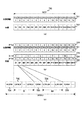
図3は、本発明の実施の形態におけるデータ構造の一例を示す図である。ここで、図3(a)は原画像の単位画像と位置情報との関係を示す図である。この例では、動画像712は15フレームの単位画像(B1乃至P15)によりGOP710を構成し、各単位画像に対応して位置情報711(POS1乃至15)が取得されている。
FIG. 3 is a diagram showing an example of a data structure in the embodiment of the present invention. Here, FIG. 3A is a diagram showing the relationship between the unit image of the original image and the position information. In this example, the moving
単位画像712において、I3はIピクチャを示し、B1、B2、B4、B5、B7、B8、B10、B11,B13、B14は、Bピクチャを示し、P6、P9、P12、P15はPピクチャを示す。各サフィックス番号は、ピクチャタイプに関係なく、フレーム単位の連続番号を付与したものである。一方、位置情報711において、POS1乃至15は各サフィックス番号の画像フレーム(単位画像)についての位置情報を示している。すなわち、位置情報POS1乃至15のそれぞれは、サフィックス番号が同一である画像フレームについての位置情報となっている。
In the
図3(a)の原画像の単位画像712は、画像符号化部2110の並換え部2111により図3(b)の単位画像722に示すようなピクチャ順の並び換えがなされる。これに対して、位置情報の並び順は変更されないため、図3(b)に示す位置情報721は、図3(a)の位置情報711と同じ並び順となっている。したがって、並び順だけでは各ピクチャと位置情報との対応関係がつかめない。
The
そこで、多重化部2140において、各単位画像および位置情報に対して再生出力の時間管理情報であるタイムスタンプPTSが付加される。図3(b)において、PTS723は位置情報721のタイムスタンプPTSを示し、PTS724は単位画像722のタイムスタンプPTSを示す。再生出力は元のフレーム順であり、各ピクチャのサフィックス番号とタイムスタンプPTS724とは等しくなっている。これらPTS723およびPTS724を対応させることにより、位置情報と各単位画像とが関連付けられ、位置情報がいずれの単位画像についてのものであるかの対応付けをすることができる。
Therefore, in the
また、単位画像722にはタイムスタンプDTS725が付加される。上述のとおり、このタイムスタンプDTSは復号の時刻管理情報であり、圧縮データ(すなわち、MPEG−2 PS形式)では各単位画像はこのタイムスタンプDTSの順に並んでいる。なお、タイムスタンプDTS725はタイムスタンプPTS724と一致する場合には付与されない。従って、この図3(b)の例では、タイムスタンプDTS725はIピクチャおよびPピクチャに付与されるが、Bピクチャには付与されない。
A
図3(c)は、図3(b)の各データを多重化した後のデータ構造を示す図である。ナビゲーションパック731(NV_PCK)は、各GOPに対応するパック群の先頭に位置付けられ、データサーチインフォメーション(例えば、ジャンプ時にどのセクタまで飛ぶかを指示する制御情報)などの再生管理情報を保持する。なお、後述のDVDフォーマットにおいては、一つのGOPに対応するパック群を動画オブジェクト単位(VOBU:Video OBject Unit)という。 FIG. 3C is a diagram showing a data structure after multiplexing each data of FIG. 3B. The navigation pack 731 (NV_PCK) is positioned at the head of the pack group corresponding to each GOP, and holds reproduction management information such as data search information (for example, control information instructing which sector to fly to when jumping). In the DVD format described later, a pack group corresponding to one GOP is called a video object unit (VOBU).
パック群732(V_PCK_I3)は、単位画像I3に相当する画像データを保持する。DVDフォーマットでは、1パック当り2048バイトの容量となっているため、画像データの容量がこれを超える場合には複数のパックに分割して保持される。パック733(P_PCK1)は、位置情報POS1に相当する位置情報を保持する。パック群734(V_PCK_B1)は、単位画像B1に相当する画像データを保持する。また、パック735(P_PCK2)は、位置情報POS2に相当する位置情報を保持する。 The pack group 732 (V_PCK_I3) holds image data corresponding to the unit image I3. Since the DVD format has a capacity of 2048 bytes per pack, if the capacity of the image data exceeds this, it is divided and held in a plurality of packs. The pack 733 (P_PCK1) holds position information corresponding to the position information POS1. The pack group 734 (V_PCK_B1) holds image data corresponding to the unit image B1. The pack 735 (P_PCK2) holds position information corresponding to the position information POS2.
このように、符号化の際に並び換えられた順に従って単位画像が位置情報と多重化される。図3(c)の例では、パック733をパック群732とパック群734との間に多重化しているが、これは単位画像同士または位置情報同士が入れ換わらなければよく、例えば、パック733をパック群732の前に配置したり、パック群734の後に配置するようにしてもよい。また、位置情報721をまとめて配置してもよい。
Thus, the unit images are multiplexed with the position information in the order rearranged at the time of encoding. In the example of FIG. 3C, the
また、この図3の例では、単位画像の全てについてそれぞれの位置情報を保持するようにしているが、この単位画像と位置情報の対応は必ずしも1対1でなくてもよい。例えば、単位画像N(N:自然数)個おきに対応する位置情報を保持するようにしてもよく、また、1GOP毎に位置情報を保持するようにしてもよい。 Further, in the example of FIG. 3, the position information is held for all the unit images, but the correspondence between the unit images and the position information is not necessarily one-to-one. For example, position information corresponding to every unit image N (N: natural number) may be held, or position information may be held for each GOP.
なお、この図3では音声信号については省略しているが、音声信号も併せて多重化できることは従来と同様である。 Although the audio signal is omitted in FIG. 3, the audio signal can be multiplexed together as in the conventional case.
図4は、本発明の実施の形態における符号化/復号回路21の復号機能の一構成例を示す図である。この復号機能は、分離部2160と、システム時刻保持部2170と、バッファ2161乃至2163と、画像復号部2171と、音声復号部2172と、位置情報処理部2173と、バッファ2181乃至2183と、制御部2190とを備える。
FIG. 4 is a diagram showing a configuration example of the decoding function of the encoding /
分離部2160は、多重化されたデータ(すなわち、MPEG−2 PS形式)から画像信号、音声信号、および、位置情報を分離する。これら画像信号、音声信号、および、位置情報は、バッファ2161乃至2163にそれぞれ保持される。また、分離部2160は、それぞれのパックからパックヘッダおよびパケットヘッダを分離し、それらのヘッダ情報をシステム時刻保持部2170および制御部2190に供給する。
The
システム時刻保持部2170は、復号機能に用いられるシステム時刻(STC:System Time Clock)を保持するものである。このシステム時刻保持部2170は、分離部2160から供給されたパックヘッダに含まれるシステム時刻基準参照値(SCR)によって自己の保持するシステム時刻(STC)を設定する。このシステム時刻(STC)は、制御部2190に供給される。
The system
画像復号部2171は、制御部2190の制御に従って、バッファ2161に保持された画像信号をタイムスタンプDTSに従った順序で復号し、フレーム単位の画像データに復元してバッファ2181に出力する。音声復号部2172は、制御部2190の制御に従って、バッファ2162に保持された音声信号を復号し、音声データに復元してバッファ2182に出力する。位置情報処理部2173は、制御部2190の制御に従って、フレーム単位の画像データ(単位画像)についての位置情報を再生し、バッファ2183に出力する。
Under the control of the
制御部2190は、分離部2160から供給されたヘッダ情報を解析し、タイムスタンプPTSおよびDTSを抽出して、画像信号、音声信号および位置情報の復号処理および再生出力を制御する。画像復号部2171では、単位画像はタイムスタンプDTSに従って順序で復号されてバッファ2181に保持されるが、制御部2190による制御により、バッファ2181からタイムスタンプPTSに従った順序で単位画像のデータが出力される。制御部2190は、バッファ2182および2183からの出力も同様にタイムスタンプPTSに従った順序で供給されるように制御する。
The
また、制御部2190は、バッファ2181乃至2183から出力処理部24に対して出力される画像信号、音声信号および位置情報のタイムスタンプPTSが一致するようにタイミングを同期させるよう制御する。すなわち、システム時刻保持部2170から供給されるシステム時刻(STC)と各パケットヘッダにおけるタイムスタンプPTSが一致するタイミングでバッファ2181乃至2183から出力処理部24に対して画像信号、音声信号および位置情報が出力される。これにより、圧縮データにおいて並び順が異なっていた画像信号の単位画像と位置情報とが関連付けられて出力される。
In addition, the
図5は、本発明の実施の形態におけるディスク49に用いられるフォーマットの一例としてのDVD−Videoフォーマットのデータ構造を示す図である。ディスク49の記録エリアは、ディスクの半径方向に見て、最内周側から順に、リードインエリア801、ファイル管理エリア802、データ記録エリア803、リードアウトエリア804の順に区分けされる。
FIG. 5 is a diagram showing a data structure of a DVD-Video format as an example of a format used for the disk 49 in the embodiment of the present invention. The recording area of the disk 49 is divided into a lead-in
ファイル管理エリア802は、リードインエリア側から、UDF(Universal Disc Format)エリアおよびVMG(Video ManaGer)エリアを含む。これらUDFエリアおよびVMGエリアは、DVDに記録された画像データ等のファイルを管理する管理用情報の記録エリアである。UDFエリアは、UDF規格とISO9660規格をサポートすることにより、コンピュータでDVDを読むことができるようにするためのものである。VMGエリアは、DVD管理用情報の記録エリアである。
The
データ記録エリア803は、画像信号や音声信号等を記録するエリアであり、ビデオタイトルセット(VTS:Video Title Set)811と呼ばれるデータ群を単位として、データの記録がなされる。ビデオタイトルセット820の各々は、ビデオタイトルセット情報(VTSI:Video Title Set Information)821と、ビデオタイトルセットメニュー(VTSM_VOBS:Video Object Set for the VTSM)822と、ビデオタイトルセットタイトル(VTSTT_VOBS:Video Object Set for Titles in a VTS)823と、バックアップ(VTSI(BUP):Back-UP of VTSI)824とからなる。
The
ビデオタイトルセット情報(VTSI)821は、ビデオタイトルセットに対する制御情報である。ビデオタイトルセットメニュー(VTSM_VOBS)822は、ビデオタイトルセット内の各種メニューのためのコンテンツである。ビデオタイトルセットタイトル(VTSTT_VOBS)823は、タイトルを再生するためのコンテンツである。バックアップ(VTSI(BUP))824は、ビデオタイトルセット情報821のバックアップコピーである。
Video title set information (VTSI) 821 is control information for the video title set. The video title set menu (VTSM_VOBS) 822 is content for various menus in the video title set. The video title set title (VTSTT_VOBS) 823 is content for reproducing the title. A backup (VTSI (BUP)) 824 is a backup copy of the video title set
ビデオタイトルセットタイトル(VTSTT_VOBS)823には、MPEG−2 PSフォーマットの圧縮データが、上述の動画オブジェクト単位(VOBU)を読み書き単位として記録される。このVOBUには、1GOPに相当する画像信号やそれに対応する音声信号等が含まれる。すなわち、DVDへのアクセスは、1GOPを単位として行われることになる。 In the video title set title (VTSTT_VOBS) 823, compressed data in the MPEG-2 PS format is recorded using the above-mentioned moving image object unit (VOBU) as a read / write unit. This VOBU includes an image signal corresponding to 1 GOP, an audio signal corresponding to the image signal, and the like. That is, access to the DVD is performed in units of 1 GOP.
動画オブジェクト単位(VOBU)は、複数個のパック841から構成される。パック841は、一般に一または複数個のパケットからなるが、この例では、一つのパックは一つのパケットを含むものとしている。すなわち、1パックは、パケットの前にパックヘッダ851を付加したものであり、さらにパケットはパケットヘッダ852とデータ本体であるパケットデータ853とを備える。なお、DVD−Videoフォーマットでは、1パックは2048バイト(1セクタに対応)と定められている。
The moving image object unit (VOBU) is composed of a plurality of
パックヘッダ851は、パックの開始を示すパック開始コード861のほか、システム時刻基準参照値(SCR)862を含む。このシステム時刻基準参照値(SCR)862は、上述のようにシステム時刻発生部2150に基づくものである。なお、MPEG−2 PSでは27MHzで時刻を示すため、このシステム時刻基準参照値(SCR)862は、パックヘッダ851においては42ビットで表現される。
The
パケットヘッダ852は、プライベート1・パケットに沿ったものであり、パケット開始コード871と、フラグ873と、PTS875と、DTS876と、その他のフィールド877を備える。パケット開始コード871はパケットの開始を示すものであり、ストリームを識別するストリーム識別子を含む。フラグ873は、後続のPTS875およびDTS876の存在を示すフラグを含む。すなわち、「10」でPTS875のみ、「11」でPTS875およびDTS876が存在することを示す。
The
PTS875およびDTS876は上述のように、それぞれ再生出力のタイミングおよび復号のタイミングを示すタイムスタンプである。制御部2190は、これらPTS875およびDTS876を参照することにより復号および再生出力を制御する。なお、これらPTS875およびDTS876は、パケットヘッダ852においてはそれぞれ33ビットで表現される。
As described above, PTS875 and DTS876 are time stamps indicating the timing of reproduction output and the timing of decoding, respectively. The
なお、ここでは、プライベート1・パケットを適用した例について説明したが、プライベート2・パケットを適用しても構わない。例えば、複数の位置情報をそれぞれのPTSと対にして一つのパックに格納するようにしても構わない。また、ここでは、DVD−Videoフォーマットの適用例について説明したが、他のフォーマットを適用しても構わない。例えば、DVD−VRフォーマットにおけるVOBUの先頭に配置されるパックRDI_PCK内のRDIパケットのRDI・データ領域内に位置情報を保持するようにしてもよい。 Here, an example in which private 1 packet is applied has been described, but private 2 packet may be applied. For example, a plurality of pieces of position information may be paired with each PTS and stored in one pack. Although an example of applying the DVD-Video format has been described here, another format may be applied. For example, the position information may be held in the RDI data area of the RDI packet in the pack RDI_PCK arranged at the head of the VOBU in the DVD-VR format.
図6は、本発明の実施の形態におけるファイル管理テーブルの一例を示す図である。このファイル管理テーブルは、例えばDVD−Videoフォーマットにおけるファイル管理エリア802に保持するようにしてもよく、また、データ記録エリア803の所定位置もしくは所定ファイル名として保持するようにしてもよい。このファイル管理テーブルは、ディスク49に記録されている各ファイルに関する属性データとして、作成日891と、更新日892と、題名893と、キーワード894と、開始アドレス895とを含む。
FIG. 6 is a diagram showing an example of the file management table in the embodiment of the present invention. This file management table may be held in, for example, a
作成日891は、対応するファイルが作成された日を表す。また、更新日892は、対応するファイルが更新された日を表す。題名893は、対応するファイルの内容を識別するためにユーザによって付与されるものである。キーワード894は、対応するファイルの検索に役立てるためにユーザによって任意に付与されるものである。これらの内容は検索の際の絞込み条件として利用することができる。
The
開始アドレス895は、対応するファイルの開始アドレスを示すものであり、ディスク49内のセクタまたはアドレス等を示す。これにより、ファイル管理テーブルと各ファイルとの対応付けがなされる。
The
このファイル管理テーブルを設けることにより、ディスク49上に記録されているファイルの内容を効率良く検索することができ、ディスク49のシークに要する時間を短縮することができる。このファイル管理テーブルを使用しない場合にはディスク49上のファイルを逐一検索する必要があるが、これらをまとめてファイル管理テーブルにより管理することによって検索に要する時間を短縮することができる。 By providing this file management table, the contents of the files recorded on the disk 49 can be searched efficiently, and the time required for seeking the disk 49 can be shortened. When this file management table is not used, it is necessary to search for files on the disk 49 one by one. By managing these files collectively using the file management table, the time required for the search can be shortened.
図7は、本発明の実施の形態における画面表示例を示す図である。この画面表示例は、あるディスク49の内容を地図上に表示したものである。このディスク49には2つのファイルが含まれていることを想定して、それらの撮影の際の位置の履歴が地図上の位置情報311および312として表示部42に表示された例を示している。題名313および314は、位置情報311および312により表されるファイルのそれぞれの題名を示している。
FIG. 7 is a diagram showing a screen display example in the embodiment of the present invention. In this screen display example, the contents of a certain disk 49 are displayed on a map. Assuming that this disk 49 includes two files, the history of positions at the time of shooting is displayed on the
この表示例において、位置情報311の何れかの部分について、例えばマウスのクリック等のような指示が操作入力部41によりなされると、この位置情報311に対応するファイルの再生が行われる。例えば、位置情報311の開始位置(矢印の根元)がクリックされると、この位置情報311に対応するファイルの最初から再生が行われる。また、位置情報311の途中部分がクリックされると、クリックされた位置に対応する場面(単位画像)から動画像信号の再生が行われる。
In this display example, when an instruction such as a mouse click is given to any part of the
また、位置情報312には開始位置から終了位置までの間にアイコン315乃至317が表示されている。これらアイコン315乃至317は、対応する位置における代表画像を示すものであり、例えば対応する位置のGOPにおけるIピクチャを代表画像として用いることができる。これらアイコン315乃至317が指示されると、そのアイコンに対応する場面(単位画像)から動画像信号の再生が行われる。
Further,
なお、アイコンの表示に関しては、所定の間隔で表示する方法、アイコン数を指定して等間隔となる位置で表示する方法、指定された任意の位置で表示する方法等、種々の方法が考えられる。 As for the icon display, various methods such as a method of displaying at a predetermined interval, a method of specifying the number of icons at a position at equal intervals, and a method of displaying at a specified arbitrary position are conceivable. .
このように位置情報を地図上に表示することにより、記録媒体としてのディスクに記録された動画像を、地図という親しみのある画像により管理することができ、ユーザの使い勝手を向上することができる。これにより、動画像の頭出しが容易に行われるようになる。 By displaying the position information on the map in this way, it is possible to manage a moving image recorded on a disk as a recording medium by using a friendly image called a map, and to improve user convenience. As a result, the moving image can be easily cued.
図8は、本発明の実施の形態における表示制御部36の一構成例を示す図である。表示部42には、図7のような地図が表示されるだけでなく、動画像信号の再生画面も表示される。その際、地図の表示と動画像の表示とを片方ずつ別々に表示するだけでなく、同時に表示することが望ましい。そこで、表示制御部36に、重ね合せ回路361を設けて、地図に関して描画された地図プレーン341と動画像を表示した動画プレーン342とを重ね合せた上で表示部42に表示する。その表示例が図9および図10である。
FIG. 8 is a diagram showing a configuration example of the
図9は、本発明の実施の形態における重ね合せによる画面表示の一例を示す図である。この表示例では、動画プレーン342の上に地図プレーン341が重ねられて表示されている。
FIG. 9 is a diagram showing an example of a screen display by superposition according to the embodiment of the present invention. In this display example, a
地図プレーン341は、動画プレーン342において再生中の動画がどのような道筋で撮影されたかを地図上の矢印により表示している。この表示例では、ファイル中に記録されている動画像データ全体の道筋が地図プレーン341における矢印の始点(根元)から終点(先端)にかけて表示されており、矢印内の模様の変化により現在の再生位置が示されている。すなわち、地図プレーン341における矢印の模様の区切りの位置が現在の再生位置ということになる。これにより、ユーザは、動画像がどのような道筋で撮像されたかを容易に知ることができ、また現在再生中の画面が全体のどの位置にあるのかを視覚的に把握することが可能となる。
The
なお、この表示例では動画像データ全体の道筋を地図プレーン341上の矢印により表しているが、このように動画像データ全体を表示せずに実際に再生された部分を矢印により表示するようにしてもよい。この場合、動画プレーン342に動画が再生されるのと同期して、地図プレーン341上の矢印が伸びていくことになる。
In this display example, the path of the entire moving image data is represented by an arrow on the
図10は、本発明の実施の形態における重ね合せによる画面表示の他の例を示す図である。この表示例では、地図プレーン341の上に動画プレーン342が重ねられて表示されている。操作入力部41による指示により、図9の表示例と図10の表示例との間で相互に表示の切換えが可能である。例えば、図9の表示において地図の詳細表示が必要となった場合には図10の表示例への切換えを指示することが考えられる。
FIG. 10 is a diagram showing another example of the screen display by superposition according to the embodiment of the present invention. In this display example, a moving
なお、この図10の表示例においては、再生位置を示す地図プレーン341上の矢印が画面の左上に配置されているが、例えば、この矢印の先端が画面の中心に配置されるように表示してもよい。上述のように動画が再生されるのと同期して矢印が伸びていくようにした場合、そのままでは地図プレーン341の下に矢印が隠れてしまうおそれがあるが、矢印の先端が常に画面の中心に配置されるように表示すれば地図プレーン341の下に矢印が隠れるおそれもなくなり、ユーザが現在再生されている位置を容易に把握することができる。
In the display example of FIG. 10, the arrow on the
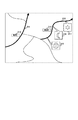
図11は、本発明の実施の形態における位置情報の履歴の表示形態について示す図である。動画像を撮影する場合、それぞれの内容の性質によって示す履歴が大きく異なってくる可能性がある。例えば、図11の「北海道旅行」や「九州旅行」のように移動範囲が広い場合には、広域地図においても撮影された道筋を十分に表現することができる。一方、比較的局所的な範囲に留まっている場合には広域地図では撮影された道筋を十分に表現することができなくなる。 FIG. 11 is a diagram showing a display form of a history of position information in the embodiment of the present invention. When shooting a moving image, there is a possibility that the history shown varies greatly depending on the nature of each content. For example, when the travel range is wide, such as “Hokkaido trip” or “Kyushu trip” in FIG. 11, the route taken on the wide area map can be sufficiently expressed. On the other hand, when the area stays in a relatively local area, the captured route cannot be expressed sufficiently on the wide area map.
そこで、図11の「散歩1」等のように、表示されている地図の領域に比較して道筋が狭い領域に閉じている場合には、矢印により道筋を表さずに、円形の表示を行う。この円形表示の大きさは、移動距離の最大値に比例するように設定することができる。また、その領域に含まれるファイルの数に応じた大きさに設定するようにしてもよい。なお、この円形表示に対する題名の表示は、その領域が操作入力部41により選択された際(例えばマウスポインタがその領域の上に存在する際)にのみ表示するようにしてもよい。
Therefore, when the path is closed in a narrow area compared to the displayed map area, such as “
円形表示を行うか否かの基準として、例えば、縦M×横Nの地図において、縦方向の移動範囲の最大幅がM/kより小さく、且つ、横方向の移動距離の最大幅がN/kより小さい場合には履歴を円形で表示するようにする。ここで、基準となるkには例えば10乃至20程度の値を選択することができる。また、縦方向の移動距離の最大幅の二乗と横方向の移動距離の最大幅の二乗とを加えた値が(M2+N2)/k2より小さい場合に履歴を円形で表示するようにしてもよい。 As a reference for whether or not to perform circular display, for example, in a vertical M × N horizontal map, the maximum width of the vertical movement range is smaller than M / k, and the maximum width of the horizontal movement distance is N / If it is smaller than k, the history is displayed in a circle. Here, for example, a value of about 10 to 20 can be selected as the reference k. In addition, when the value obtained by adding the square of the maximum width of the moving distance in the vertical direction and the square of the maximum width of the moving distance in the horizontal direction is smaller than (M 2 + N 2 ) / k 2 , the history is displayed in a circle. May be.
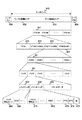
図12は、本発明の実施の形態における位置情報の履歴の他の表示形態について示す図である。図11の地図において、「野球観戦、ハイキング、結婚式」と表示された円形部分が操作入力部41により指示(例えばマウスによるクリック)されると、その拡大地図として図12のような地図が表示される。 FIG. 12 is a diagram showing another display form of the position information history in the embodiment of the present invention. In the map of FIG. 11, when the circular portion displayed as “baseball watching, hiking, wedding” is instructed by the operation input unit 41 (for example, clicked with the mouse), a map as shown in FIG. 12 is displayed as an enlarged map. Is done.
この表示例では、例えば「ハイキング」のように地図の領域を基準として道筋が比較的広い範囲にあるものは、矢印により位置情報が表示されている。一方、例えば「野球観戦」や「結婚式」のようにほぼ定位置または局所領域に閉じている場合には図11の場合と同様に円形に表示される。この円形表示を行うか否かの基準も図11の場合と同様である。 In this display example, for example, “Hiking”, where the path is in a relatively wide range based on the map area, the position information is displayed by arrows. On the other hand, when it is almost closed at a fixed position or local area, such as “watching baseball” or “wedding”, it is displayed in a circle as in the case of FIG. The standard for determining whether or not to perform this circular display is the same as in the case of FIG.
この図12の場合、矢印表示または円形表示のそれぞれは一つのファイルに対応しているため、それら表示の何れかが操作入力部41により指示されると、対応するファイルの再生が開始する。矢印表示が指示(クリック)された場合は図7の場合と同様であり、クリックされた位置に対応する場面(単位画像)からファイル内の動画像信号の再生が行われる。一方、円形表示が指示された場合はそのファイルの所定位置(例えば先頭)から動画像信号の再生が行われる。
In the case of FIG. 12, since each of the arrow display and the circular display corresponds to one file, when any of these displays is instructed by the
このように、本発明の実施の形態では、動画像データを含むファイルを地図上の位置情報により視覚的に管理することができる。 As described above, in the embodiment of the present invention, a file including moving image data can be visually managed by position information on a map.
図13は、本発明の実施の形態において携帯機器同士でリアルタイムに表示を行う例を示す図である。本発明によれば、ディスク49に記録された符号化データを再生するだけでなく、符号化されたデータ(すなわち、MPEG−2 PS)を通信装置60を通じてリアルタイムでやりとりすることができる。
FIG. 13 is a diagram illustrating an example in which display is performed in real time between portable devices in the embodiment of the present invention. According to the present invention, not only can the encoded data recorded on the disk 49 be reproduced, but also the encoded data (ie, MPEG-2 PS) can be exchanged in real time through the
携帯機器111と121との間で通信を行っている際、携帯機器111の画面には、携帯機器121により撮像された動画像112が表示されるとともに互いの現在位置を含む地図113が表示される。この地図113には、説明表示114にも示されているように、携帯機器111および121の現在位置を示すマークが表示される。また、通信の途中で携帯機器111または121が移動した場合にはその軌跡が太線により表示される。すなわち、移動軌跡を表す太線の先端に現在位置を示すマークが表示されることになる。
When communication is performed between the
携帯機器121の画面にも同様に、携帯機器111により撮像された動画像122が表示されるとともに互いの現在位置を含む地図123が表示される。これにより、携帯機器111および121のユーザは互いに通信相手の表情を認識するとともに、互いの位置関係を容易に把握することができる。
Similarly, on the screen of the
なお、携帯機器の画面には相手に携帯機器からの動画像だけでなく、自身の携帯機器による撮像画像(例えば、携帯機器121における撮像画像125)を表示して、その写り具合を確認できるようにしてもよい。また、図13では動画像を大きく表示するようにしているが、図10の例のように地図を大きく表示するよう適宜切換えるようにしてもよく、また、地図のみを表示するようにしてもよい。
In addition, not only a moving image from the mobile device but also a captured image of the mobile device (for example, a captured
このように、本発明の実施の形態では、動画像データを含むファイルを記録媒体に記録して利用するだけでなく、通信装置60を通じて位置情報を動画像信号と関連付けて送信することにより、通信相手の地図上の位置関係をリアルタイムに把握することができる。
As described above, in the embodiment of the present invention, not only a file including moving image data is recorded and used on a recording medium, but also communication is performed by transmitting positional information in association with a moving image signal through the
次に、本発明の実施の形態における地図の取得方法について説明する。 Next, a map acquisition method according to the embodiment of the present invention will be described.
本発明のように表示すべき地図の範囲が不確定な場合、どの範囲までの地図を用意するべきかは事前にはわからない。ユーザの移動範囲を予測することは不可能だからである。従って、日本国内で使用される携帯機器であれば、日本全域の細部にわたる地図を用意する必要がある。これは予め各携帯機器に具備するようにしてもよいが、以下のような方法により外部から通信を介して取得することも可能である。 When the range of the map to be displayed is uncertain as in the present invention, it is not known in advance which range of the map should be prepared. This is because it is impossible to predict the movement range of the user. Therefore, if it is a portable device used in Japan, it is necessary to prepare a detailed map of the entire area of Japan. This may be provided in each portable device in advance, but can also be acquired from outside through communication by the following method.
ここでは説明を簡単にするために、基地局Aが発する電波領域Aから基地局Bが発する電波領域Bまで移動する場合を考える。本発明の実施の形態における携帯機器を持ったユーザが基地局Aの発する電波領域Aに入った場合、基地局Aとの通信を確立し接続する。その際、基地局Aからは、基地局Aから発せられる電波の到達範囲よりもやや広範囲の地図データが携帯機器に送信され、機器は地図データを受信する。次に、基地局AおよびBからの電波が混在する電波領域Cに移動した場合、携帯機器は、基地局Aとの通信を行いながら、基地局Bの電波を受信する。基地局Bの電波の強さがAより強くなると、電波チャネルを切り替えるハンドオーバーが発生し、通信を基地局Bに切り替える。そして、基地局Bから基地局Aから発せられる電波の到達範囲よりもやや広範囲の地図データが携帯機器に送信され、携帯機器は地図データを受信する。 Here, in order to simplify the explanation, consider a case where the mobile station moves from a radio wave area A emitted from the base station A to a radio wave area B emitted from the base station B. When a user with a portable device in the embodiment of the present invention enters the radio wave region A emitted by the base station A, communication with the base station A is established and connected. At that time, the base station A transmits map data of a slightly wider range than the reach of radio waves emitted from the base station A to the mobile device, and the device receives the map data. Next, when moving to a radio wave region C in which radio waves from the base stations A and B are mixed, the mobile device receives radio waves from the base station B while communicating with the base station A. When the radio wave strength of the base station B becomes stronger than A, a handover for switching the radio channel occurs, and the communication is switched to the base station B. Then, map data slightly wider than the reach of radio waves emitted from the base station A from the base station B is transmitted to the mobile device, and the mobile device receives the map data.
また、地図の種類としては日本全図のような広域地図から道路地図のような細部を網羅する地図まで段階に応じた地図を想定することができる。そして、同じ階層の地図は互いに境界領域が重なるようにやや広めの範囲を有するものとしておき、重複する部分については、携帯機器は後から取得した地図における重複部分を削除してマッチングを行い、マッチング終了後に新たな地図としてメモリに記録する。 In addition, as the type of map, a map according to the stage can be assumed from a wide area map such as a full map of Japan to a map that covers details such as a road map. The maps in the same hierarchy should have a slightly wider range so that the boundary areas overlap each other, and for overlapping parts, the mobile device deletes the overlapping parts in the map acquired later and performs matching. After completion, record as a new map in memory.
通信により地図を取得する場合、撮像の直前の状態であるスタンバイ状態になったときに受信するようにしてもよく、また、携帯機器の電源が通電している状態には常に受信するようにして不要な地図は適宜廃棄するようにしてもよい。後者の場合には、受信された地図を一時記録するメモリ(例えば、RAM34)の領域に応じて随時上書きするようにすればよい。 When a map is acquired by communication, it may be received when it enters a standby state, which is the state immediately before imaging, and it is always received when the power of the portable device is energized. You may make it discard an unnecessary map suitably. In the latter case, the received map may be overwritten as needed depending on the area of the memory (for example, RAM 34) in which the received map is temporarily recorded.
なお、地図にはその地図の範囲における名所案内に関する情報を含ませるようにしてもよい。その場合、その名所に最も近い位置情報を有するファイルについてファイル管理テーブルのキーワード894にその名称を登録しておけば、後日の検索の際に利用することができる。また、名所案内の動画像データを含むファイルを地図と併せて受信して、別個のファイルとしてファイル管理テーブルに登録するようにしてもよい。この場合、地図上の名所案内のアイコン等をクリックすることにより、名所案内の動画像データが再生されるようにすることができる。
In addition, you may make it include the information regarding the sights guidance in the range of the map in a map. In that case, if the name of the file having the position information closest to the famous place is registered in the
なお、本発明の実施の形態では、位置情報を符号化データの内部に保持しているが、位置情報の範囲を予めファイル管理テーブルに登録しておくようにしても構わない。 In the embodiment of the present invention, the position information is held in the encoded data, but the range of the position information may be registered in the file management table in advance.
次に、本発明の実施の形態における動作について説明する。 Next, the operation in the embodiment of the present invention will be described.
図14は、本発明の実施の形態における携帯機器とユーザとのやりとりを説明するための図である。まず、本発明の実施の形態における位置情報を含むディスク49をユーザが携帯機器100に挿入するか、もしくは、ディスク49のマウントまたはリロードを操作入力部41により要求すると(201)、携帯機器100は図6で説明したファイル管理テーブルをディスク49から読み出して、このファイル管理テーブルにおける各ファイルに対応する位置情報を地図上に描画して表示部42に表示する(101)。
FIG. 14 is a diagram for explaining exchanges between the mobile device and the user in the embodiment of the present invention. First, when the user inserts the disk 49 including the position information in the embodiment of the present invention into the
表示部42に表示された地図において位置情報の表示(上述の矢印表示や円形表示)をユーザが操作入力部41により指示すると(202)、携帯機器100はディスク49における対応するファイルにアクセスして、所定位置から動画像信号の再生を行う(103)。これにより、ユーザは地図上の位置情報から動画像へのアクセスを容易に行うことができる。
When the user instructs the
図15は、本発明の実施の形態におけるディスク全体の内容を表示する処理の手順を示す図である。すなわち、この図15は図14における処理101の手順を示すものである。携帯機器100は、ファイル管理テーブルに基づいてディスク49に記録されているファイルの内容を動画オブジェクト単位(VOBU)毎に読み出して、符号化/復号回路21において復号処理を行う(ステップS911)。これにより、動画像信号と関連付けられた位置情報が得られる。
FIG. 15 is a diagram showing a procedure of processing for displaying the contents of the entire disc in the embodiment of the present invention. That is, FIG. 15 shows the procedure of the
そして、このようにして得られた位置情報の範囲が既に所有している地図の範囲内に収まるものであるか否かを判断し(ステップS912)、もし所有している地図の範囲内に収まらないと判断した場合には必要な地図を通信装置60を通じて取得する(ステップS913)。 Then, it is determined whether or not the range of position information obtained in this way is within the range of the already owned map (step S912), and if it is within the range of the owned map. If it is determined that there is not, a necessary map is acquired through the communication device 60 (step S913).
携帯機器100は、地図上にその動画オブジェクト単位の位置情報を描画する(ステップS914)。そして、その動画オブジェクト単位がファイルの最後になるまで(ステップS915)、ステップS911乃至S914の処理を繰り返す。
The
ファイルの最後まで処理を終えると(ステップS915)、携帯機器100はファイル管理テーブルに保持されている題名893を抽出して地図上の位置情報に付する(ステップS916)。そして、次のファイルが存在する場合には(ステップS917)、次のファイルの処理に移る(ステップS918)。
When the processing is completed to the end of the file (step S915), the
次のファイルが存在しない場合には(ステップS917)、携帯機器100はこれまでに描画された位置情報を含む地図を表示部42に表示する(ステップS919)。
When the next file does not exist (step S917), the
図16は、本発明の実施の形態におけるファイルの内容を表示する処理の手順を示す図である。すなわち、この図16は図14における処理103の手順を示すものである。携帯機器100は、指定されたファイルの所定画面から復号処理を行う(ステップS931)。これにより、動画像信号と関連付けられた位置情報が得られる。なお、ここで所定画面とは、矢印表示が指示された場合にはその位置に対応する画面であり、また円形表示によるファイルの場合は例えばファイルの先頭の画面とすることができる。
FIG. 16 is a diagram showing a procedure of processing for displaying the contents of a file in the embodiment of the present invention. That is, FIG. 16 shows the procedure of the
そして、このようにして得られた位置情報の範囲が既に所有している地図の範囲内に収まるものであるか否かを判断し(ステップS932)、もし所有している地図の範囲内に収まらないと判断した場合には必要な地図を、通信装置60を通じて取得する(ステップS933)。 Then, it is determined whether or not the range of position information obtained in this way is within the range of the already owned map (step S932), and if it is within the range of the owned map. If it is determined that there is no map, a necessary map is acquired through the communication device 60 (step S933).
携帯機器100は、地図上にその動画オブジェクト単位の位置情報を描画して(ステップS934)、その地図を動画像とともに表示部42に表示する(ステップS935)。携帯機器100は、これらの処理を動画像データの最後まで、もしくは、ユーザにより再生中止が指示されるまで繰り返す(ステップS936)。
The
このように、本発明の実施の形態によれば、符号化/復号回路21において動画像信号の単位画像および位置情報にタイムスタンプPTSを付して両者を関連付けることにより、その位置情報に基づいて地図上に動画像の撮像された軌跡を表示させることができる。
As described above, according to the embodiment of the present invention, the encoding /
なお、本発明の実施の形態では、位置情報の取得の際にGPSを用いる例について説明したが、GPSの代わりに、3つの基地局から電波を受信して3点測位を行うことにより位置情報を特定するようにしてもよい。この場合、距離の測定は、電波に乗った信号(例えば、画像のフィールド同期信号)が到達するまでに要した時間を測定することにより実現することができる。 In the embodiment of the present invention, an example in which GPS is used when acquiring position information has been described. However, position information is obtained by receiving radio waves from three base stations and performing three-point positioning instead of GPS. May be specified. In this case, the distance can be measured by measuring a time required for a signal (for example, an image field synchronization signal) on the radio wave to arrive.
また、本発明の実施の形態は本発明を具現化するための一例を示したものであり、以下に示すように特許請求の範囲における発明特定事項とそれぞれ対応関係を有するが、これに限定されるものではなく本発明の要旨を逸脱しない範囲において種々の変形を施すことができる。 Further, the embodiment of the present invention shows an example for embodying the present invention, and has a corresponding relationship with the invention specific matter in the claims as shown below, but is not limited thereto. However, various modifications can be made without departing from the scope of the present invention.
なお、本発明の実施の形態において説明した処理手順は、これら一連の手順を有する方法として捉えてもよく、また、これら一連の手順をコンピュータに実行させるためのプログラム乃至そのプログラムを記憶する記録媒体として捉えてもよい。 The processing procedure described in the embodiment of the present invention may be regarded as a method having a series of these procedures, and a program for causing a computer to execute these series of procedures or a recording medium storing the program May be taken as
10 カメラ部
11 光学ブロック
12 カメラ制御部
13 信号変換器
14 撮像信号処理部
15 音声入力部
16 音声信号処理部
20 記録再生処理部
21 符号化/復号回路
23 ディスクインターフェース
24 出力処理部
25 バッファメモリ
27〜29 出力端子
30 制御部
31 処理装置
32 システムバス
33 ROM
34 RAM
35 操作入力インターフェース
36 表示制御部
37 メモリカードインターフェース
38 通信インターフェース
39 時計回路
41 操作入力部
42 表示部
43 メモリカード
49 ディスク
50 GPSモジュール
60 通信装置
100 携帯機器
2101〜2103、2119、2129、2139、2161〜2163、2181〜2183 バッファ
2110 画像符号化部
2111 並換え部
2112 圧縮符号化部
2113 可変長符号化部
2120 音声符号化部
2130 位置情報処理部
2140 多重化部
2150 システム時刻発生部
2160 分離部
2170 システム時刻保持部
2171 画像復号部
2172 音声復号部
2173 位置情報処理部
2190 制御部
DESCRIPTION OF
34 RAM
35
Claims (5)
前記動画像データの撮影位置を示す地図データが保持される地図保持部と、
前記動画像データおよび前記地図データを表示するとともに、表示される前記地図データの領域および前記動画像データが撮影された移動範囲に基づいて、前記動画像データの撮影された道筋を示す表示を行うか否かを制御する表示制御部と
を具備する電子機器。 A moving image data holding unit that holds moving image data and position information where the moving image data is captured;
A map holding unit for holding map data indicating a shooting position of the moving image data;
The moving image data and the map data are displayed, and a display showing the path of the moving image data taken is performed based on the area of the displayed map data and the moving range where the moving image data was taken. An electronic device comprising a display control unit that controls whether or not.
請求項1記載の電子機器。 The display control unit includes a first display mode that indicates a path on which the moving image data is captured on the map based on a region of the map data to be displayed and a moving range in which the moving image data is captured; The electronic device according to claim 1, wherein a second display mode that does not indicate a route taken by the moving image data on the map is selected.
請求項1記載の電子機器。 In the display showing the path of the moving image data taken, a playback unit for starting playback of the moving image data with the position as the shooting position based on the position selected by the user in the information indicating the path The electronic device according to claim 1, further comprising:
前記動画像データおよび前記地図データを表示する手順と、
表示される前記地図データの領域および前記動画像データが撮影された移動範囲に基づいて、前記動画像データの撮影された道筋を示す表示を行うか否かを制御する手順と
を具備する表示制御方法。 Display in an electronic apparatus comprising a moving image data holding unit that holds moving image data and position information at which the moving image data was shot, and a map holding unit that holds map data indicating the shooting position of the moving image data A control method,
A procedure for displaying the moving image data and the map data;
Display control comprising: a step of controlling whether or not to display a path of the moving image data captured based on an area of the map data to be displayed and a moving range in which the moving image data is captured Method.
前記動画像データおよび前記地図データを表示する手順と、
表示される前記地図データの領域および前記動画像データが撮影された移動範囲に基づいて、前記動画像データの撮影された道筋を示す表示を行うか否かを制御する手順と
をコンピュータに実行させるプログラム。 In an electronic apparatus comprising: a moving image data holding unit that holds moving image data and position information at which the moving image data was shot; and a map holding unit that holds map data indicating a shooting position of the moving image data.
A procedure for displaying the moving image data and the map data;
And causing the computer to execute a procedure for controlling whether or not to display the path of the moving image data captured based on the area of the map data to be displayed and the moving range in which the moving image data is captured. program.
Priority Applications (1)
| Application Number | Priority Date | Filing Date | Title |
|---|---|---|---|
| JP2008329559A JP4798215B2 (en) | 2008-12-25 | 2008-12-25 | Electronics |
Applications Claiming Priority (1)
| Application Number | Priority Date | Filing Date | Title |
|---|---|---|---|
| JP2008329559A JP4798215B2 (en) | 2008-12-25 | 2008-12-25 | Electronics |
Related Parent Applications (1)
| Application Number | Title | Priority Date | Filing Date |
|---|---|---|---|
| JP2006019957A Division JP4937592B2 (en) | 2006-01-30 | 2006-01-30 | Electronics |
Publications (2)
| Publication Number | Publication Date |
|---|---|
| JP2009153143A true JP2009153143A (en) | 2009-07-09 |
| JP4798215B2 JP4798215B2 (en) | 2011-10-19 |
Family
ID=40921650
Family Applications (1)
| Application Number | Title | Priority Date | Filing Date |
|---|---|---|---|
| JP2008329559A Expired - Fee Related JP4798215B2 (en) | 2008-12-25 | 2008-12-25 | Electronics |
Country Status (1)
| Country | Link |
|---|---|
| JP (1) | JP4798215B2 (en) |
Cited By (2)
| Publication number | Priority date | Publication date | Assignee | Title |
|---|---|---|---|---|
| JP2019161318A (en) * | 2018-03-08 | 2019-09-19 | 株式会社Hysエンジニアリングサービス | Mobile information transmission system |
| JP7075610B1 (en) | 2021-08-27 | 2022-05-26 | 西武建設株式会社 | Video generation system |
Citations (8)
| Publication number | Priority date | Publication date | Assignee | Title |
|---|---|---|---|---|
| JPH05323872A (en) * | 1992-05-21 | 1993-12-07 | Sumitomo Electric Ind Ltd | Course display device |
| JPH08154228A (en) * | 1994-11-28 | 1996-06-11 | Sharp Corp | Camcorder |
| JPH10143640A (en) * | 1996-11-15 | 1998-05-29 | Nippon Lsi Card Kk | Portable computer, information management system using it and strepscropic map creating method using it |
| JPH1127609A (en) * | 1997-06-30 | 1999-01-29 | Minolta Co Ltd | Image recording and reproducing system |
| JPH11259502A (en) * | 1998-03-11 | 1999-09-24 | Mitsubishi Electric Corp | Image information display device |
| JP2001194172A (en) * | 2000-01-14 | 2001-07-19 | Hitachi Ltd | Navigation system and information distribution device |
| JP2001229165A (en) * | 1999-12-07 | 2001-08-24 | Sony Corp | Device and method for information processing and program storage medium |
| JP2002191015A (en) * | 2000-09-29 | 2002-07-05 | Casio Comput Co Ltd | Picked-up image management device, picked-up image management method and picked-up image management program |
-
2008
- 2008-12-25 JP JP2008329559A patent/JP4798215B2/en not_active Expired - Fee Related
Patent Citations (8)
| Publication number | Priority date | Publication date | Assignee | Title |
|---|---|---|---|---|
| JPH05323872A (en) * | 1992-05-21 | 1993-12-07 | Sumitomo Electric Ind Ltd | Course display device |
| JPH08154228A (en) * | 1994-11-28 | 1996-06-11 | Sharp Corp | Camcorder |
| JPH10143640A (en) * | 1996-11-15 | 1998-05-29 | Nippon Lsi Card Kk | Portable computer, information management system using it and strepscropic map creating method using it |
| JPH1127609A (en) * | 1997-06-30 | 1999-01-29 | Minolta Co Ltd | Image recording and reproducing system |
| JPH11259502A (en) * | 1998-03-11 | 1999-09-24 | Mitsubishi Electric Corp | Image information display device |
| JP2001229165A (en) * | 1999-12-07 | 2001-08-24 | Sony Corp | Device and method for information processing and program storage medium |
| JP2001194172A (en) * | 2000-01-14 | 2001-07-19 | Hitachi Ltd | Navigation system and information distribution device |
| JP2002191015A (en) * | 2000-09-29 | 2002-07-05 | Casio Comput Co Ltd | Picked-up image management device, picked-up image management method and picked-up image management program |
Cited By (3)
| Publication number | Priority date | Publication date | Assignee | Title |
|---|---|---|---|---|
| JP2019161318A (en) * | 2018-03-08 | 2019-09-19 | 株式会社Hysエンジニアリングサービス | Mobile information transmission system |
| JP7075610B1 (en) | 2021-08-27 | 2022-05-26 | 西武建設株式会社 | Video generation system |
| JP2023032639A (en) * | 2021-08-27 | 2023-03-09 | 西武建設株式会社 | video generation system |
Also Published As
| Publication number | Publication date |
|---|---|
| JP4798215B2 (en) | 2011-10-19 |
Similar Documents
| Publication | Publication Date | Title |
|---|---|---|
| JP4168837B2 (en) | Information generating apparatus, recording apparatus, reproducing apparatus, recording / reproducing system, method thereof, and program | |
| JP4937592B2 (en) | Electronics | |
| US8599243B2 (en) | Image processing device, image processing method, and program | |
| CN100334642C (en) | Recording method and apparatus, recording medium, reproducing method and apparatus and imaging apparatus | |
| EP1691369A1 (en) | Apparatus and method for playback of still and moving pictures | |
| US20090228508A1 (en) | Recording Device and Method, Imaging Apparatus, Playing Device and Method, and Program | |
| JP2007082088A (en) | Contents and meta data recording and reproducing device and contents processing device and program | |
| JP4506832B2 (en) | Image processing apparatus, index generation apparatus, imaging apparatus, index generation method, and program | |
| JP2012060218A5 (en) | ||
| JP4720873B2 (en) | Information recording apparatus, imaging apparatus, information recording method, and program | |
| JP5085462B2 (en) | Information recording apparatus, imaging apparatus, information recording method, and program | |
| JP4798215B2 (en) | Electronics | |
| JP4821462B2 (en) | Recording apparatus and method, reproducing apparatus and method, and program | |
| JP2008067117A (en) | Video image recording method, apparatus, and medium | |
| JP2006092681A (en) | Image management method, image management device and image management system | |
| JP2005135554A (en) | Reproducing device and method | |
| JP2010074271A (en) | Reproduction device, reproduction method, image processing device, and image processing method | |
| JP2006254475A (en) | Imaging apparatus and imaging method | |
| JP2016042406A (en) | Video recording device | |
| JP2013131287A (en) | Video recording device and video recording method | |
| JP2015079556A (en) | Video recording device | |
| JP2014149909A (en) | Video recording device | |
| JP2012038411A (en) | Video recording device | |
| JP2012156756A (en) | Display device | |
| JP2008199502A (en) | Video camera |
Legal Events
| Date | Code | Title | Description |
|---|---|---|---|
| A621 | Written request for application examination |
Free format text: JAPANESE INTERMEDIATE CODE: A621 Effective date: 20081225 |
|
| TRDD | Decision of grant or rejection written | ||
| A01 | Written decision to grant a patent or to grant a registration (utility model) |
Free format text: JAPANESE INTERMEDIATE CODE: A01 Effective date: 20110705 |
|
| A01 | Written decision to grant a patent or to grant a registration (utility model) |
Free format text: JAPANESE INTERMEDIATE CODE: A01 |
|
| A61 | First payment of annual fees (during grant procedure) |
Free format text: JAPANESE INTERMEDIATE CODE: A61 Effective date: 20110718 |
|
| FPAY | Renewal fee payment (event date is renewal date of database) |
Free format text: PAYMENT UNTIL: 20140812 Year of fee payment: 3 |
|
| R151 | Written notification of patent or utility model registration |
Ref document number: 4798215 Country of ref document: JP Free format text: JAPANESE INTERMEDIATE CODE: R151 |
|
| FPAY | Renewal fee payment (event date is renewal date of database) |
Free format text: PAYMENT UNTIL: 20140812 Year of fee payment: 3 |
|
| R250 | Receipt of annual fees |
Free format text: JAPANESE INTERMEDIATE CODE: R250 |
|
| R250 | Receipt of annual fees |
Free format text: JAPANESE INTERMEDIATE CODE: R250 |
|
| R250 | Receipt of annual fees |
Free format text: JAPANESE INTERMEDIATE CODE: R250 |
|
| R250 | Receipt of annual fees |
Free format text: JAPANESE INTERMEDIATE CODE: R250 |
|
| R250 | Receipt of annual fees |
Free format text: JAPANESE INTERMEDIATE CODE: R250 |
|
| R250 | Receipt of annual fees |
Free format text: JAPANESE INTERMEDIATE CODE: R250 |
|
| R250 | Receipt of annual fees |
Free format text: JAPANESE INTERMEDIATE CODE: R250 |
|
| LAPS | Cancellation because of no payment of annual fees |