JP2009151221A - Illuminator, image display apparatus, and polarization conversion/diffusion member - Google Patents
Illuminator, image display apparatus, and polarization conversion/diffusion member Download PDFInfo
- Publication number
- JP2009151221A JP2009151221A JP2007330805A JP2007330805A JP2009151221A JP 2009151221 A JP2009151221 A JP 2009151221A JP 2007330805 A JP2007330805 A JP 2007330805A JP 2007330805 A JP2007330805 A JP 2007330805A JP 2009151221 A JP2009151221 A JP 2009151221A
- Authority
- JP
- Japan
- Prior art keywords
- light
- laser light
- polarization conversion
- image display
- display device
- Prior art date
- Legal status (The legal status is an assumption and is not a legal conclusion. Google has not performed a legal analysis and makes no representation as to the accuracy of the status listed.)
- Pending
Links
Images


Classifications
-
- G—PHYSICS
- G03—PHOTOGRAPHY; CINEMATOGRAPHY; ANALOGOUS TECHNIQUES USING WAVES OTHER THAN OPTICAL WAVES; ELECTROGRAPHY; HOLOGRAPHY
- G03B—APPARATUS OR ARRANGEMENTS FOR TAKING PHOTOGRAPHS OR FOR PROJECTING OR VIEWING THEM; APPARATUS OR ARRANGEMENTS EMPLOYING ANALOGOUS TECHNIQUES USING WAVES OTHER THAN OPTICAL WAVES; ACCESSORIES THEREFOR
- G03B33/00—Colour photography, other than mere exposure or projection of a colour film
- G03B33/10—Simultaneous recording or projection
- G03B33/12—Simultaneous recording or projection using beam-splitting or beam-combining systems, e.g. dichroic mirrors
-
- G—PHYSICS
- G02—OPTICS
- G02B—OPTICAL ELEMENTS, SYSTEMS OR APPARATUS
- G02B27/00—Optical systems or apparatus not provided for by any of the groups G02B1/00 - G02B26/00, G02B30/00
- G02B27/28—Optical systems or apparatus not provided for by any of the groups G02B1/00 - G02B26/00, G02B30/00 for polarising
- G02B27/281—Optical systems or apparatus not provided for by any of the groups G02B1/00 - G02B26/00, G02B30/00 for polarising used for attenuating light intensity, e.g. comprising rotatable polarising elements
-
- G—PHYSICS
- G02—OPTICS
- G02B—OPTICAL ELEMENTS, SYSTEMS OR APPARATUS
- G02B27/00—Optical systems or apparatus not provided for by any of the groups G02B1/00 - G02B26/00, G02B30/00
- G02B27/48—Laser speckle optics
-
- G—PHYSICS
- G03—PHOTOGRAPHY; CINEMATOGRAPHY; ANALOGOUS TECHNIQUES USING WAVES OTHER THAN OPTICAL WAVES; ELECTROGRAPHY; HOLOGRAPHY
- G03B—APPARATUS OR ARRANGEMENTS FOR TAKING PHOTOGRAPHS OR FOR PROJECTING OR VIEWING THEM; APPARATUS OR ARRANGEMENTS EMPLOYING ANALOGOUS TECHNIQUES USING WAVES OTHER THAN OPTICAL WAVES; ACCESSORIES THEREFOR
- G03B21/00—Projectors or projection-type viewers; Accessories therefor
- G03B21/14—Details
- G03B21/20—Lamp housings
- G03B21/2073—Polarisers in the lamp house
-
- G—PHYSICS
- G03—PHOTOGRAPHY; CINEMATOGRAPHY; ANALOGOUS TECHNIQUES USING WAVES OTHER THAN OPTICAL WAVES; ELECTROGRAPHY; HOLOGRAPHY
- G03B—APPARATUS OR ARRANGEMENTS FOR TAKING PHOTOGRAPHS OR FOR PROJECTING OR VIEWING THEM; APPARATUS OR ARRANGEMENTS EMPLOYING ANALOGOUS TECHNIQUES USING WAVES OTHER THAN OPTICAL WAVES; ACCESSORIES THEREFOR
- G03B21/00—Projectors or projection-type viewers; Accessories therefor
- G03B21/14—Details
- G03B21/20—Lamp housings
- G03B21/208—Homogenising, shaping of the illumination light
Landscapes
- Physics & Mathematics (AREA)
- General Physics & Mathematics (AREA)
- Optics & Photonics (AREA)
- Projection Apparatus (AREA)
- Diffracting Gratings Or Hologram Optical Elements (AREA)
- Polarising Elements (AREA)
Abstract
Description
本発明は、照明装置、画像表示装置及び偏光変換拡散部材に関する。 The present invention relates to an illumination device, an image display device, and a polarization conversion diffusing member.
近年、照明装置により光変調装置を照明し、その光変調装置から射出された画像光を投射レンズ等の投射光学系によりスクリーンに拡大投射するプロジェクタが広く知られている。
そのプロジェクタの照明装置として、従来はメタルハライドランプやハロゲンランプ等が利用されていたが、近年では照明装置およびプロジェクタの小型化を図るため、半導体レーザ(LD)の利用が提案されている。レーザ光源の利点として、小型化以外にも、色再現性がよいことや、輝度およびコントラストの高い映像表示が可能であること、瞬時点灯が可能であることなどが挙げられる。
2. Description of the Related Art In recent years, projectors that illuminate a light modulation device with an illumination device and enlarge and project image light emitted from the light modulation device onto a screen using a projection optical system such as a projection lens are widely known.
Conventionally, metal halide lamps, halogen lamps, and the like have been used as illumination devices for the projectors, but in recent years, use of semiconductor lasers (LDs) has been proposed in order to reduce the size of the illumination devices and projectors. Advantages of the laser light source include not only miniaturization but also good color reproducibility, video display with high brightness and contrast, and instant lighting.
しかしながら、レーザ光はコヒーレント光であるため、拡大投射された映像光には、明点および暗点がランダムに分布したスペックルパターンが生じる。スペックルパターンは、投射光学系の各点からの出射光が不規則な位相関係で干渉することによって生じるものである。このスペックルパターンを有する映像は、観察者にぎらぎらとしたちらつき感を与えるため問題である。 However, since the laser light is coherent light, a speckle pattern in which bright spots and dark spots are randomly distributed is generated in the enlarged projected image light. The speckle pattern is generated when light emitted from each point of the projection optical system interferes with an irregular phase relationship. An image having this speckle pattern is a problem because it gives a glare and glimmer to the observer.
この問題を解決するため、光源から射出された光を拡散板により拡散させ、スペックルノイズを低減させる画像表示装置が提案されている(例えば、特許文献1〜3参照。)。
特許文献1に記載のディスプレイ装置では、レーザ光源から射出された光は拡散素子により拡散され、拡散された光はレンズにより空間的光変調器に集束される。そして、空間的光変調器によって画像に変換された光は観察面に表示される。
In order to solve this problem, an image display device has been proposed in which light emitted from a light source is diffused by a diffusion plate to reduce speckle noise (see, for example,
In the display device described in
また、特許文献2に記載の投射型画像表示装置では、第1次元表示素子から射出された光はガルバノミラーにより走査され、走査された光は振動しているディフューザを通過する。これにより、ディフューザから射出された光は拡散されて、投射レンズによりスクリーン上に拡大投射される。 In the projection type image display device described in Patent Document 2, the light emitted from the first dimensional display element is scanned by a galvanometer mirror, and the scanned light passes through a vibrating diffuser. Thereby, the light emitted from the diffuser is diffused and projected on the screen by the projection lens.
また、特許文献3に記載の画像表示システムでは、第1の光学系により、光源から射出された光による中間像が光拡散角変換素子上に形成され、光拡散角変換素子に入射する入射角より光拡散角変換素子から射出される射出角を大きくする。そして、光拡散角変換素子を振動させることにより、スペックルパターンの時間的変化が人間の眼において積分され、スペックルノイズを低減することが可能となる。
しかしながら、上記特許文献1,2に記載の技術では、拡散板により光源から射出された光を拡散させてスペックルノイズを低減させているが、拡散板だけでは、人間の眼で知覚できないレベルまでスペックルノイズを低減することは難しい。
また、特許文献3の技術では、光拡散角変換素子の散乱角と投射レンズの飲み込み角との関係を最適化することにより、多くの散乱パターンをスクリーン上に投影できるため、明るく、かつ、スペックルを低減した画像を投影可能である。しかしながら、この構成の場合も人間の眼で知覚できないレベルまでスペックルノイズを低減することは難しい。
However, in the techniques described in
In the technique of Patent Document 3, since many scattering patterns can be projected on the screen by optimizing the relationship between the scattering angle of the light diffusion angle conversion element and the swallowing angle of the projection lens, it is bright and has specs. It is possible to project an image with reduced noise. However, even in this configuration, it is difficult to reduce speckle noise to a level that cannot be perceived by human eyes.
本発明は、上記の課題を解決するためになされたものであって、より確実にスペックルノイズを低減することが可能な照明装置、画像表示装置及び偏光変換拡散部材を提供することを目的とする。 The present invention has been made to solve the above-described problems, and an object thereof is to provide an illumination device, an image display device, and a polarization conversion diffusing member that can more reliably reduce speckle noise. To do.
上記目的を達成するために、本発明は、以下の手段を提供する。
本発明の照明装置は、レーザ光を射出するレーザ光源と、該レーザ光源から射出されたレーザ光を複数種の偏光方向に変換して射出させる複数の領域を有する偏光変換部とを備え、前記レーザ光源から射出されたレーザ光、あるいは、前記偏光変換部から射出されたレーザ光を拡散させ被投射面を照明することを特徴とする。
In order to achieve the above object, the present invention provides the following means.
An illumination device of the present invention includes a laser light source that emits laser light, and a polarization conversion unit that has a plurality of regions that convert the laser light emitted from the laser light source into a plurality of types of polarization directions and emit the laser light, Laser light emitted from a laser light source or laser light emitted from the polarization converter is diffused to illuminate a projection surface.
本発明に係る照明装置では、レーザ光源から射出されたレーザ光は、例えば、偏光変換素子に入射した後、拡散される。すなわち、領域ごとに偏光方向が変換されたレーザ光が拡散される。したがって、偏光方向の異なるレーザ光同士は干渉しないため、スペックルノイズが低減したレーザ光により被投射面を照明することが可能となる。 In the illumination device according to the present invention, the laser light emitted from the laser light source is diffused after entering the polarization conversion element, for example. That is, the laser light whose polarization direction is converted for each region is diffused. Therefore, laser beams having different polarization directions do not interfere with each other, and thus the projection surface can be illuminated with the laser light with reduced speckle noise.
また、本発明の照明装置は、拡散されたレーザ光、あるいは、前記偏光変換部から射出されたレーザ光を前記被投射面に投射する投射手段を備えることが好ましい。 Moreover, it is preferable that the illuminating device of this invention is provided with the projection means which projects the diffused laser beam or the laser beam inject | emitted from the said polarization conversion part on the said projection surface.
本発明に係る照明装置では、拡散されたレーザ光、あるいは、偏光変換部から射出されたレーザ光は、投射手段により被投射面に投射される。このような照明装置をレーザ加工機、レーザ露光機に用いた場合、スペックルノイズが抑えられたレーザ光により被投射面を照射することができるため、レーザ加工、レーザ露光を精度良く行うことが可能となる。 In the illumination device according to the present invention, the diffused laser light or the laser light emitted from the polarization conversion unit is projected onto the projection surface by the projection unit. When such an illuminating device is used in a laser processing machine or a laser exposure machine, the projection surface can be irradiated with laser light with reduced speckle noise, so that laser processing and laser exposure can be performed with high accuracy. It becomes possible.
本発明の画像表示装置は、レーザ光を射出するレーザ光源と、該レーザ光源から射出されたレーザ光を複数種の偏光方向に変換して射出させる複数の領域を有する偏光変換部と、前記レーザ光源から射出されたレーザ光を画像信号に応じて変調する光変調装置と、該光変調装置により変調されたレーザ光を被投射面に投射する投射手段とを備え、前記レーザ光源から射出されたレーザ光を拡散させ前記被投射面を照射することを特徴とする。 An image display apparatus according to the present invention includes a laser light source that emits laser light, a polarization conversion unit that includes a plurality of regions that convert the laser light emitted from the laser light source into a plurality of types of polarization directions, and the laser. A light modulation device that modulates laser light emitted from a light source according to an image signal, and a projection unit that projects the laser light modulated by the light modulation device onto a projection surface, are emitted from the laser light source. Laser light is diffused to irradiate the projection surface.
本発明に係る画像表示装置では、レーザ光源から射出されたレーザ光は、光変調装置により画像信号に応じて変調され、変調されたレーザ光は投射手段により被投射面に投射される。このとき、被投射面に投射されるレーザ光は、例えば、光変調装置により変調され、偏光変換素子に入射した後、拡散される。すなわち、光変調装置から射出された画像は領域ごとに偏光方向が変換されて拡散される。そして、拡散された偏光方向の異なるレーザ光が被投射面に投射される。したがって、偏光方向の異なるレーザ光同士は干渉しないので、被投射面に投射される画像のスペックルノイズを低減することが可能となる。 In the image display device according to the present invention, the laser light emitted from the laser light source is modulated in accordance with the image signal by the light modulation device, and the modulated laser light is projected onto the projection surface by the projection means. At this time, the laser light projected on the projection surface is modulated by, for example, a light modulation device, is incident on the polarization conversion element, and is then diffused. That is, the image emitted from the light modulation device is diffused by changing the polarization direction for each region. Then, the diffused laser beams having different polarization directions are projected onto the projection surface. Therefore, since laser beams having different polarization directions do not interfere with each other, it is possible to reduce speckle noise of an image projected on the projection surface.
また、本発明の画像表示装置は、前記偏光変換部には凹部が形成され、該凹部により前記レーザ光源から射出されたレーザ光を拡散させることが好ましい。
本発明に係る画像表示装置では、偏光変換部には凹部が形成され、凹部によりレーザ光源から射出されたレーザ光を拡散させるため、装置全体の小型化、低コスト化を図ることが可能となる。
In the image display device according to the aspect of the invention, it is preferable that a concave portion is formed in the polarization converter, and the laser light emitted from the laser light source is diffused by the concave portion.
In the image display device according to the present invention, a concave portion is formed in the polarization converter, and the laser light emitted from the laser light source is diffused by the concave portion, so that the entire device can be reduced in size and cost. .
また、本発明の画像表示装置は、前記偏光変換部には凹部が形成され、前記レーザ光源から射出されたレーザ光を拡散させる光拡散部を備えることが好ましい。 In the image display device of the present invention, it is preferable that a concave portion is formed in the polarization conversion unit, and a light diffusion unit that diffuses laser light emitted from the laser light source is provided.
本発明に係る画像表示装置では、光拡散部により、レーザ光源から射出されたレーザ光、あるいは、偏光変換部から射出されたレーザ光を拡散させる。すなわち、光拡散部を備えることにより、より確実にレーザ光を拡散させることができるため、被投射面に投射される画像のスペックルノイズをより効果的に低減させることが可能となる。 In the image display device according to the present invention, the laser beam emitted from the laser light source or the laser beam emitted from the polarization conversion unit is diffused by the light diffusion unit. That is, by providing the light diffusing unit, the laser light can be more reliably diffused, so that speckle noise of an image projected on the projection surface can be more effectively reduced.
また、本発明の画像表示装置は、前記偏光変換部及び前記光拡散部が、前記光変調装置と前記被投射面との間の光路上に配置され、少なくとも前記光拡散部が、前記光変調装置から射出されたレーザ光により中間像が形成される位置に配置されていることが好ましい。 In the image display device of the present invention, the polarization conversion unit and the light diffusion unit are disposed on an optical path between the light modulation device and the projection surface, and at least the light diffusion unit includes the light modulation unit. It is preferably arranged at a position where an intermediate image is formed by laser light emitted from the apparatus.
本発明に係る画像表示装置では、光変調装置により変調されたレーザ光は、例えば、偏光変換部により領域ごとに偏光方向が変換されて、光拡散部により拡散される。このとき、中間像が形成される位置に、光拡散部が配置されているため、光拡散部により中間像を拡散して被投射面に画像を投射する。したがって、被投射面に投射される画像のスペックルノイズをより確実に低減することが可能となる。 In the image display device according to the present invention, the laser light modulated by the light modulation device is diffused by the light diffusion unit after the polarization direction is converted for each region by the polarization conversion unit, for example. At this time, since the light diffusing unit is disposed at a position where the intermediate image is formed, the intermediate image is diffused by the light diffusing unit and the image is projected onto the projection surface. Therefore, speckle noise of an image projected on the projection surface can be more reliably reduced.
また、本発明の画像表示装置は、前記光変調装置と前記光拡散部との間の光路上に中間像形成光学系が配置され、前記中間像形成光学系により前記中間像が形成されることが好ましい。 In the image display device of the present invention, an intermediate image forming optical system is disposed on an optical path between the light modulation device and the light diffusing unit, and the intermediate image is formed by the intermediate image forming optical system. Is preferred.
本発明に係る画像表示装置では、光変調装置により変調されたレーザ光は、中間像形成光学系により中間像が形成され、光拡散部により拡散される。また、偏光変換部により、被投射面に投射されるレーザ光の偏光方向は、領域ごとに異なるため、被投射面に投射される画像のスペックルノイズを低減することが可能となる。
したがって、中間像形成光学系により中間像を形成することで、より確実に光拡散部の位置に中間像を形成することができるため、被投射面に投射される画像のスペックルノイズをより確実に低減することが可能となる。
In the image display device according to the present invention, the laser light modulated by the light modulation device forms an intermediate image by the intermediate image forming optical system and is diffused by the light diffusion portion. In addition, since the polarization direction of the laser light projected onto the projection surface is different for each region by the polarization conversion unit, it is possible to reduce speckle noise in the image projected onto the projection surface.
Therefore, by forming the intermediate image with the intermediate image forming optical system, the intermediate image can be more reliably formed at the position of the light diffusing portion, so speckle noise of the image projected on the projection surface can be more reliably generated. It becomes possible to reduce it.
また、本発明の画像表示装置は、前記偏光変換部及び前記光拡散部が、前記光源と前記光変調装置との間の光路上に配置され、前記光変調装置が、反射型光変調装置であることが好ましい。 In the image display device of the present invention, the polarization conversion unit and the light diffusion unit are disposed on an optical path between the light source and the light modulation device, and the light modulation device is a reflection type light modulation device. Preferably there is.
本発明に係る画像表示装置では、偏光変換部及び光拡散部が、光源と光変調装置との間の光路上に配置されているため、例えば、偏光変換部により領域ごとに偏光方向の異なったレーザ光が拡散部材により拡散されて光変調装置に入射する。そして、拡散された偏光方向の異なるレーザ光が被投射面に投射される。このとき、偏光方向の異なるレーザ光同士は干渉しないので、被投射面に投射される画像のスペックルノイズを低減することが可能となる。すなわち、本発明では、光変調装置と被投射面との間の光路上に偏光変換部及び光拡散部を配置する構成に比べて、中間像を形成する必要がないため、装置全体の小型化を図ることが可能となる。 In the image display device according to the present invention, since the polarization conversion unit and the light diffusion unit are arranged on the optical path between the light source and the light modulation device, for example, the polarization conversion unit has different polarization directions for each region. The laser light is diffused by the diffusing member and enters the light modulation device. Then, the diffused laser beams having different polarization directions are projected onto the projection surface. At this time, since laser beams having different polarization directions do not interfere with each other, it is possible to reduce speckle noise of an image projected on the projection surface. That is, in the present invention, it is not necessary to form an intermediate image as compared with the configuration in which the polarization conversion unit and the light diffusion unit are arranged on the optical path between the light modulation device and the projection surface. Can be achieved.
また、本発明の画像表示装置は、前記偏光変換部が前記投射手段の開口絞りまたは瞳位置に配置されていることが好ましい。
本発明に係る画像表示装置では、偏光変換部が投射手段の開口絞りまたは瞳位置に配置されているため、様々な空間周波数に異なる偏光情報を与えることが可能となる。したがって、被投射面に投射される画像のスペックルノイズをより低減することが可能となる。
In the image display device of the present invention, it is preferable that the polarization conversion unit is disposed at an aperture stop or a pupil position of the projection unit.
In the image display device according to the present invention, since the polarization conversion unit is arranged at the aperture stop or the pupil position of the projection means, it is possible to give different polarization information to various spatial frequencies. Therefore, it is possible to further reduce speckle noise in the image projected on the projection surface.
また、本発明の画像表示装置は、基材の一方の面に前記偏光変換部が形成され、前記一方の面と反対の他方の面に前記光拡散部が形成されていることが好ましい。 In the image display device of the present invention, it is preferable that the polarization conversion unit is formed on one surface of a substrate and the light diffusion unit is formed on the other surface opposite to the one surface.
本発明に係る画像表示装置では、基材の一方の面に偏光変換部が形成され、一方の面と反対の他方の面に光拡散部が形成されているため、一括成形することができる。さらに、1つの基材に光拡散部と偏光変換部とが形成されているため、光拡散部と偏光変換部との間に界面が発生しない。したがって、界面を有する場合に生じる迷光の発生を抑えることが可能となるため、所定の範囲内に、光源から射出されたレーザ光を拡散させることが可能となる。 In the image display device according to the present invention, since the polarization conversion portion is formed on one surface of the base material and the light diffusion portion is formed on the other surface opposite to the one surface, it can be molded in a lump. Furthermore, since the light diffusion part and the polarization conversion part are formed on one base material, an interface does not occur between the light diffusion part and the polarization conversion part. Accordingly, since it is possible to suppress the generation of stray light that occurs when the interface is present, the laser light emitted from the light source can be diffused within a predetermined range.
また、本発明の画像表示装置は、前記光拡散部が前記他方の面に2つの光を干渉させることにより形成されることが好ましい。 In the image display device of the present invention, it is preferable that the light diffusing portion is formed by causing two lights to interfere with the other surface.
本発明に係る画像表示装置では、2つの光を干渉させることにより光拡散部が形成されるため、光拡散部により高次回折光の発生を制御することができる。すなわち、2つの光を照射し、不要な高次回折光が発生しないような光拡散部を形成することにより、光の利用効率を向上させることが可能となる。 In the image display device according to the present invention, since the light diffusing portion is formed by causing two lights to interfere with each other, generation of high-order diffracted light can be controlled by the light diffusing portion. That is, it is possible to improve the light utilization efficiency by irradiating two lights and forming a light diffusion portion that does not generate unnecessary high-order diffracted light.
また、本発明の画像表示装置は、前記光拡散部が回折素子であることが好ましい。
本発明に係る画像表示装置では、光拡散部が回折素子であるため、光拡散部において拡散されるレーザ光の拡散角を所定の範囲内にすることができる。したがって、レーザ光の利用効率を向上させることが可能となる。
In the image display device of the present invention, it is preferable that the light diffusion portion is a diffraction element.
In the image display device according to the present invention, since the light diffusion portion is a diffraction element, the diffusion angle of the laser light diffused in the light diffusion portion can be within a predetermined range. Therefore, it becomes possible to improve the utilization efficiency of laser light.
また、本発明の画像表示装置は、前記偏光変換部及び前記光拡散部のうち、一方が前記光源と前記光変調装置との間に配置され、他方が前記光変調装置と前記被投射面との間に配置されていることが好ましい。 In the image display device of the present invention, one of the polarization conversion unit and the light diffusion unit is disposed between the light source and the light modulation device, and the other is the light modulation device and the projection surface. It is preferable to arrange | position between.
本発明に係る画像表示装置では、偏光変換部と、光拡散部とが、光変調装置の前段側あるいは後段側に別々に設けられているため、偏光変換部及び光拡散部の配置の自由度が向上する。 In the image display device according to the present invention, since the polarization conversion unit and the light diffusion unit are separately provided on the front side or the rear side of the light modulation device, the degree of freedom of arrangement of the polarization conversion unit and the light diffusion unit Will improve.
また、本発明の画像表示装置は、前記光変調装置が、透過型の液晶素子であり、前記偏光変換部が、前記液晶素子と前記被投射面との間の光路上に配置され、前記光拡散部が、前記光源と前記液晶素子との間の光路上に配置されていることが好ましい。 In the image display device of the present invention, the light modulation device is a transmissive liquid crystal element, the polarization conversion unit is disposed on an optical path between the liquid crystal element and the projection surface, and the light It is preferable that the diffusing portion is disposed on an optical path between the light source and the liquid crystal element.
本発明に係る画像表示装置では、光変調装置が、透過型の液晶素子であり、偏光変換部と、光拡散部とが、液晶素子の前段側あるいは後段側に別々に配置させる場合は、液晶素子と被投射面との間の光路上に偏光変換部を配置し、光源と液晶素子との間の光路上に光拡散部を配置する。すなわち、光変調装置が液晶素子である場合、偏光部材を用いて特定の偏光方向のレーザ光を光変調装置に入射させている。そこで、偏光変換部を液晶素子の後段側に配置することにより、効率良く領域ごとに偏光方向の異なるレーザ光を被投射面に投射することが可能となる。 In the image display device according to the present invention, when the light modulation device is a transmissive liquid crystal element, and the polarization conversion unit and the light diffusion unit are separately disposed on the front side or the rear side of the liquid crystal element, the liquid crystal device A polarization conversion unit is disposed on the optical path between the element and the projection surface, and a light diffusion unit is disposed on the optical path between the light source and the liquid crystal element. That is, when the light modulation device is a liquid crystal element, laser light having a specific polarization direction is made incident on the light modulation device using a polarizing member. Therefore, by arranging the polarization conversion section on the rear side of the liquid crystal element, it becomes possible to efficiently project laser beams having different polarization directions for each region onto the projection surface.
また、本発明の画像表示装置は、前記偏光変換部により前記光源から射出されたレーザ光の偏光方向を前記領域ごとに変換した後、変換されたレーザ光を前記光拡散部により拡散させることが好ましい。 In the image display device of the present invention, after the polarization direction of the laser light emitted from the light source is converted by the polarization conversion unit for each region, the converted laser light is diffused by the light diffusion unit. preferable.
本発明に係る画像表示装置では、偏光変換部によりレーザ光の偏光方向を領域ごとに変換した後、変換されたレーザ光を光拡散部により拡散させる。すなわち、領域ごとに偏光方向の異なるレーザ光を拡散させているため、被投射面において偏光方向の異なるレーザ光が重畳されるので、被投射面に投射される画像のスペックルノイズをより効果的に低減することが可能となる。 In the image display device according to the present invention, after the polarization direction of the laser beam is converted for each region by the polarization conversion unit, the converted laser beam is diffused by the light diffusion unit. In other words, since laser light having a different polarization direction is diffused in each region, laser light having a different polarization direction is superimposed on the projection surface, so that speckle noise of an image projected on the projection surface is more effective. It becomes possible to reduce it.
また、本発明の画像表示装置は、前記偏光変換部は、常光線と異常光線との位相差が異なる複屈折性材料からなることが好ましい。
本発明に係る画像表示装置では、偏光変換部は、常光線と異常光線との位相差が異なる複屈折性材料からなるため、領域ごとに偏光方向を効率良く変換することが可能となる。
In the image display device according to the aspect of the invention, it is preferable that the polarization conversion unit is made of a birefringent material having different phase differences between ordinary rays and extraordinary rays.
In the image display device according to the present invention, the polarization converter is made of a birefringent material in which the phase difference between the ordinary ray and the extraordinary ray is different, so that the polarization direction can be efficiently converted for each region.
また、本発明の画像表示装置は、前記レーザ光源から射出されたレーザ光の波長をλとし、前記常光線と前記異常光線との位相差をReとすると、0≦Re≦λ/2であることが好ましい。 In the image display device of the present invention, 0 ≦ Re ≦ λ / 2, where λ is the wavelength of the laser beam emitted from the laser light source and Re is the phase difference between the ordinary ray and the extraordinary ray. It is preferable.
本発明に係る画像表示装置では、偏光変換部は、常光線と異常光線との位相差Reが、0≦Re≦λ/2の範囲である複屈折性材料からなるため、領域ごとに複数種の偏光方向のレーザ光を射出することができるため、スペックルノイズを低減することが可能となる。 In the image display device according to the present invention, the polarization converter is made of a birefringent material in which the phase difference Re between the ordinary ray and the extraordinary ray is in the range of 0 ≦ Re ≦ λ / 2. Therefore, it is possible to reduce speckle noise.
また、本発明の画像表示装置は、サンドブラスト処理により前記凹部を形成することが好ましい。
本発明に係る画像表示装置では、サンドブラスト処理により、簡易な方法で、凹部を形成することが可能となる。
In the image display device of the present invention, it is preferable that the concave portion is formed by sandblasting.
In the image display device according to the present invention, the concave portion can be formed by a simple method by sandblasting.
また、本発明の画像表示装置は、フォトリソグラフィ法及びエッチングにより前記凹部を形成することが好ましい。 In the image display device of the present invention, it is preferable to form the concave portion by photolithography and etching.
本発明に係る画像表示装置では、フォトリソグラフィ法及びエッチングにより、簡易な方法で、凹部を形成する。また、マスクの開口部の大きさや透過率を変えることにより、凹部の大きさをことができるため、サンドブラスト処理に比べて、設計通りに凹部を形成することが可能となる。 In the image display device according to the present invention, the concave portion is formed by a simple method by photolithography and etching. Further, since the size of the concave portion can be made by changing the size of the opening of the mask and the transmittance, the concave portion can be formed as designed as compared with the sandblasting process.
また、本発明の画像表示装置は、前記複数の領域の1つの大きさが、前記光変調装置の画像形成領域の大きさより小さいことが好ましい。 In the image display device of the present invention, it is preferable that the size of one of the plurality of regions is smaller than the size of the image forming region of the light modulation device.
本発明に係る画像表示装置では、複数の領域の1つの大きさが、光変調装置の画像形成領域の大きさより小さいため、画像形成領域から射出された画像は、偏光変換部を通過した際、偏光方向の異なる複数の領域に分割される。したがって、領域ごとに偏光方向の異なる画像が被投射面に投射されるため、スペックルノイズを確実に低減することが可能となる。 In the image display device according to the present invention, since the size of one of the plurality of regions is smaller than the size of the image forming region of the light modulation device, when the image emitted from the image forming region passes through the polarization conversion unit, Divided into a plurality of regions having different polarization directions. Therefore, since images having different polarization directions for each region are projected onto the projection surface, speckle noise can be reliably reduced.
また、本発明の画像表示装置は、前記複数の領域の1つの大きさが、前記投射手段の開口絞りの大きさより小さいことが好ましい。
本発明に係る画像表示装置では、複数の領域の1つの大きさが、投射手段の開口絞りの大きさより小さいため、スペックルノイズを確実に低減することが可能となる。
In the image display device of the present invention, it is preferable that the size of one of the plurality of regions is smaller than the size of the aperture stop of the projection unit.
In the image display device according to the present invention, since the size of one of the plurality of regions is smaller than the size of the aperture stop of the projection unit, speckle noise can be reliably reduced.
また、本発明の偏光変換拡散部材は、入射したレーザ光を複数種の偏光方向に変換して射出させる複数の領域を有する偏光変換部と、入射したレーザ光を拡散させる光拡散部とを備え、基材の一方の面に前記偏光変換部が形成され、前記一方の面と反対の他方の面に前記光拡散部が形成され、前記光拡散部が前記他方の面に2つの光を干渉させることにより形成されることを特徴とする。 The polarization conversion diffusion member of the present invention includes a polarization conversion unit having a plurality of regions for converting incident laser light into a plurality of types of polarization directions and emitting the light, and a light diffusion unit for diffusing the incident laser light. The polarization conversion part is formed on one surface of the base material, the light diffusion part is formed on the other surface opposite to the one surface, and the light diffusion unit interferes with two lights on the other surface. It is characterized by being formed.
本発明に係る偏光変換拡散部材では、2つの光を干渉させることにより光拡散部が形成されるため、光拡散部により高次回折光の発生を制御することができる。すなわち、2つの光を照射し、不要な高次回折光が発生しないような拡散層を形成することにより、光の利用効率を向上させることが可能となる。 In the polarization conversion diffusing member according to the present invention, since the light diffusing portion is formed by causing two lights to interfere with each other, the generation of high-order diffracted light can be controlled by the light diffusing portion. That is, it is possible to improve the light use efficiency by irradiating two lights and forming a diffusion layer that does not generate unnecessary high-order diffracted light.
また、本発明の偏光変換拡散部材は、入射したレーザ光を複数種の偏光方向に変換して射出させる複数の領域を有する偏光変換部と、入射したレーザ光を拡散させる光拡散部とを備え、基材の一方の面に前記偏光変換部が形成され、前記一方の面と反対の他方の面に前記光拡散部が形成され、前記光拡散部が回折素子であることを特徴とする。 The polarization conversion diffusion member of the present invention includes a polarization conversion unit having a plurality of regions for converting incident laser light into a plurality of types of polarization directions and emitting the light, and a light diffusion unit for diffusing the incident laser light. The polarization conversion section is formed on one surface of the substrate, the light diffusion section is formed on the other surface opposite to the one surface, and the light diffusion section is a diffractive element.
本発明に係る偏光変換拡散部材では、基材の一方の面に偏光変換部が形成され、一方の面と反対の他方の面に光拡散部が形成され、光拡散部が回折素子である。これにより、光拡散部において拡散されるレーザ光の拡散角を所定の範囲内にすることができるため、レーザ光の利用効率を向上させることが可能となる。 In the polarization conversion diffusing member according to the present invention, the polarization conversion portion is formed on one surface of the substrate, the light diffusion portion is formed on the other surface opposite to the one surface, and the light diffusion portion is a diffraction element. As a result, the diffusion angle of the laser light diffused in the light diffusing section can be set within a predetermined range, so that the utilization efficiency of the laser light can be improved.
以下、図面を参照して、本発明に係る照明装置、画像表示装置及び拡散部材の実施形態について説明する。なお、以下の図面においては、各部材を認識可能な大きさとするために、各部材の縮尺を適宜変更している。 Hereinafter, embodiments of an illumination device, an image display device, and a diffusion member according to the present invention will be described with reference to the drawings. In the following drawings, the scale of each member is appropriately changed in order to make each member a recognizable size.
[第1実施形態]
本発明のプロジェクタの第1実施形態について、図1から図5を参照して説明する。
本実施形態においては、プロジェクタとして空間光変調装置で生成された画像情報を含む色光を投射系を介してスクリーン上に投射する投射型のプロジェクタを例に挙げて説明する。
[First Embodiment]
A projector according to a first embodiment of the invention will be described with reference to FIGS.
In the present embodiment, a projector that projects color light including image information generated by a spatial light modulation device on a screen as a projector on a screen will be described as an example.
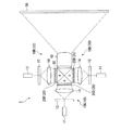
本実施形態に係るプロジェクタ(画像表示装置)1では、図1に示すように、反射型のスクリーン(被投射面)50を用い、スクリーン50の正面側からスクリーン50上に画像情報を含む光を投射する。
プロジェクタ1は、光源装置(レーザ光源)10と、光変調装置20と、ダイクロイックプリズム(色光合成手段)30と、投射装置(投射手段)40とを備えている。また、以下の説明においては、光変調装置を液晶ライトバルブと称する。
In the projector (image display device) 1 according to the present embodiment, as shown in FIG. 1, a reflective screen (projected surface) 50 is used, and light including image information is projected onto the
The
光源装置10は、赤色のレーザ光を射出する赤色光源装置(レーザ光源)10Rと、緑色のレーザ光を射出する緑色光源装置(レーザ光源)10Gと、青色のレーザ光を射出する青色光源装置(レーザ光源)10Bとからなる。
また、液晶ライトバルブ(光変調装置)20は、赤色光源装置10Rから射出されたレーザ光を画像情報に応じて光変調する2次元の透過型の赤色用光変調装置20Rと、緑色光源装置10Gから射出されたレーザ光を画像情報に応じて光変調する2次元の透過型の緑色用光変調装置20Gと、青色光源装置10Bから射出されたレーザ光を画像情報に応じて光変調する2次元の透過型の青色用光変調装置20Bとからなる。さらに、ダイクロイックプリズム30は、各光変調装置20R,20G,20Bにより変調された各色光を合成するものである。
また、投射装置40は、ダイクロイックプリズム30で合成されたレーザ光をスクリーン(被投射面)50上に投射するものである。
The
The liquid crystal light valve (light modulation device) 20 includes a two-dimensional transmissive red
The
各光源装置10R,10G,10Bは、レーザ光を射出する光源11と、光源11から射出されたレーザ光を回折する回折光学素子12と、回折光学素子12において回折したレーザ光の射出角度を調整する角度調整用光学素子14とを備えている。なお、各光源装置10R,10G,10Bの構成はこれに限るものではない。
Each of the
投射装置40について図2を用いて説明する。なお、図2は、液晶ライトバルブ20R,20G,20Bに入射したレーザ光がスクリーン50に投射される光路図を見易くするために、液晶ライトバルブ20R,20G,20B、投射装置40、スクリーン50を直線配置として示し、また、ダイクロイックプリズム30を省略している。
投射装置40は、図2に示すように、光路上に第1レンズ群41と、偏光変換板(偏光変換部)43と、第2レンズ群45とをこの順に備えている。偏光変換板43は、中心部である回転軸Pを中心にアクチュエータ(図示略)により回転される。なお、偏光変換板43の中心部を回転軸Pとしたが、これに限らず、偏光変換板43の端部を回転軸Pとしても良い。
The
As shown in FIG. 2, the
第1レンズ群(中間像形成光学系)41は、ダイクロイックプリズム30において合成されたレーザ光を偏光変換板43上またはその近傍に中間像として形成する。また、第1レンズ群41は、開口絞り42に対して略対称に配置された前段レンズ群41a、後段レンズ群41bからなる等倍結像レンズである。また、前段レンズ群41a、後段レンズ群41bは、液晶ライトバルブ20R,20G,20Bの視野角特性を考慮して両側テレセントリック特性を有することが望ましい。前段レンズ群41a、後段レンズ群41bは、複数の凸レンズおよび凹レンズを含んで構成されているが、レンズの形状、大きさ、配置間隔および枚数、テレセントリック性、倍率その他のレンズ特性は、要求される特性によって適宜変更されるものである。
The first lens group (intermediate image forming optical system) 41 forms the laser beam synthesized in the
偏光変換板43は、図3に示すように、複数の領域Aを有しており、複数種の偏光方向を有するレーザ光が複数の領域Aから射出されるようになっている。すなわち、例えば、領域A1及び領域A4から射出されたレーザ光の偏光方向は、振動方向の異なる直線偏光であり、領域A2及び領域A3から射出されるレーザ光の偏光方向は、楕円偏光となっている。なお、複数の領域Aから射出されるレーザ光の偏光方向は、すべて異なっていても、同じ偏光方向がいくつか存在していても良い。
さらに、偏光変換板43は、図3に示すように、第1レンズ群41により形成された中間像Tが形成される位置に配置されている。偏光変換板43の各領域Aの大きさは、中間像Tの大きさより小さくなっている。また、第1レンズ群41は等倍結像レンズであるため、液晶ライトバルブ20R,20G,20Bの画像形成領域の大きさが中間像Tと略同じ大きさである。したがって、偏光変換板43の各領域Aの大きさは、液晶ライトバルブ20R,20G,20Bの画像形成領域の大きさより、小さくなっている。
なお、偏光変換板43の各領域Aの大きさが開口絞り42の大きさより小さくしても良い。
本実施形態では、偏光変換板43の領域Aの大きさは、すべて同じであるが、すべて異なっていても良く、また、何種類かの大きさが混ざっていても良い。
As shown in FIG. 3, the
Further, as shown in FIG. 3, the
Note that the size of each region A of the
In the present embodiment, the sizes of the regions A of the
具体的には、偏光変換板43は、図4に示すように、ダイクロイックプリズム30から合成されたレーザ光が入射する入射端面43aと反対の射出端面43bに互いに異なる深さの複数の矩形状の凹部(凹凸構造)43Mを有している。これにより、偏光変換板43から射出されるレーザ光は拡散される。また、1つの凹部43Mが図3に示す1つの領域Aとなっている。
また、偏光変換板43は、光弾性係数の高い材料、例えば、ポリカーボネートから形成されている。そして、ポリカーボネートは、延伸時に材料に加わる応力により、延伸方向とそれと略垂直な方向とに異なる屈折率を有することが可能であり、1軸性の光学異方性を有する複屈折材料として機能する。
Specifically, as shown in FIG. 4, the
The
次に、偏光変換板43の各領域Aを通過するレーザ光の偏光方向について、図5を参照して説明する。なお、図5では、領域Aa及び領域Abから射出されるレーザ光の偏光方向を分かりやすく説明するために、他の領域Ac,Ad,Ae…の大きさより大きく図示する。また、実際には、偏光変換板43の領域Aごとにダイクロイックプリズム30によって合成されたレーザ光が入射するのではなく、入射端面43aの全体にレーザ光が入射する。
ここで、偏光変換板43を形成する材料の光弾性係数をC[Pa−1]とし、延伸時に材料に加わる応力をσ[Pa]とすると、常光線と異常光線との屈折率差は、
Next, the polarization direction of the laser light passing through each region A of the
Here, when the photoelastic coefficient of the material forming the

で表される。
また、屈折率差Δnを有する材料は、隣接する領域Aの厚みの差をdとすると、
It is represented by
In addition, a material having a refractive index difference Δn has a thickness difference between adjacent regions A as d.
の関係が成り立つ。したがって、隣接する領域Aの厚みの差dにより、常光線と異常光線とに位相差Reを与えることが可能となり、レーザ光は偏光変換板43を通過することにより、領域Aごとに偏光方向が異なる。
The relationship holds. Therefore, the phase difference Re can be given to the ordinary ray and the extraordinary ray due to the thickness difference d between the adjacent regions A, and the polarization direction of the laser light passes through the
これにより、1軸性光学異方性を有する材料からなる偏光変換板43に、偏光変換板43の材料の光軸に対して45°傾いた直線偏光の光線が入射した際に、隣接する領域Aの厚みの差dの違いにより位相差Reが異なる。すなわち、図5に示すように、偏光変換板43の射出端面43bから射出される光線の偏光方向が、領域Aごとに異なる。例えば、領域Aaから射出される射出光の偏光方向は、常光線と異常光線との光学的距離が異なり位相が同じであるため、入射光と同じ矢印B1で示す向きとなる。一方、領域Abから射出される射出光の偏光方向は、常光線と異常光線との光学的距離が異なり位相も異なるため、矢印B2で示すように、入射光と位相が90°回転した向きとなる。領域Aごとの位相差Reは、0〜λ/2の範囲であれば良い。このようにして、偏光変換板43の隣接する領域Aの厚みの差dに応じて複数種の偏光方向のレーザ光が複数の領域Aa,Ab,Ac…から射出される。
Thereby, when a linearly polarized light beam inclined by 45 ° with respect to the optical axis of the material of the
次に、以上の構成からなる本実施形態のプロジェクタ1により、スクリーン50に画像を表示する方法について説明する。
まず、各光源装置10R,10G,10Bから射出された赤色光,緑色光,青色光は、均一なレーザ光となり、角度調整用光学素子14に入射する。角度調整用光学素子14から射出された均一な赤色光,緑色光,青色光は、液晶ライトバルブ20R,20G,20Bに入射し、ダイクロイックプリズム30で合成される。
合成されたレーザ光は、第1レンズ群41を介して偏光変換板43に入射する。偏光変換板43に入射するレーザ光の偏光方向は、直線偏光となっている。そして、偏光変換板43において、領域Aごとに偏光方向が変換された後、射出端面43bで拡散される。したがって、偏光変換板43からは、偏光方向の異なる複数種の直線偏光や楕円率の異なる楕円偏光が射出される。そして、領域Aごとに偏光方向の異なる画像が、第2レンズ群45によりスクリーン50に投射される。このとき、スクリーン50に投射されるレーザ光も、領域Aごとに偏光方向の異なるレーザ光となる。
Next, a method for displaying an image on the
First, red light, green light, and blue light emitted from each of the
The combined laser light enters the
本実施形態に係るプロジェクタ1では、偏光変換板43から射出された複数種の偏光方向のレーザ光が拡散し、スクリーン50に投射される。したがって、偏光方向の異なるレーザ光同士は干渉しないため、スクリーン50に投射される画像のスペックルノイズを低減することが可能となる。
また、中間像が形成される位置に偏光変換板43が配置されているため、中間像Tを領域Aごとに偏光方向を変換し拡散するため、より確実にスペックルノイズを低減することが可能となる。また、第1レンズ群41により中間像を形成するため、より確実に偏光変換板43の位置に中間像Tを形成することが可能となる。
また、偏光変換板43が、凹部43Mを有し各光源装置10R,10G,10Bから射出されたレーザ光を拡散させるため、装置全体の小型化、低コスト化を図ることが可能となる。
In the
In addition, since the
Further, since the
また、偏光変換板43の材料として複屈折性の大きいポリカーボネートを用いているため、常光線と異常光線との位相差Reを大きくすることができる。これにより、スクリーン50に投射されるレーザ光は干渉しにくくなるため、スペックルノイズを低減することが可能となる。
つまり、本実施形態のプロジェクタ1は、より確実にスペックルノイズを低減することが可能である。
Further, since polycarbonate having a high birefringence is used as the material of the
That is, the
また、レーザ光を射出するレーザ光源と、上述した偏光変換板43と、偏光変換板43から射出された領域Aごとに偏光方向の異なる拡散されたレーザ光を被投射面に投射する投射手段とを備えた照明装置であっても良い。このような照明装置をレーザ加工機、レーザ露光機に用いた場合、スペックルノイズが抑えられたレーザ光により被投射面を照射することができるため、レーザ加工、レーザ露光を精度良く行うことが可能となる。
Also, a laser light source that emits laser light, the above-described
なお、本実施形態では、偏光変換板43を形成する材料としてポリカーボネートを用いたがこれに限るものではない。また、偏光変換板43を形成する材料は複屈折性の大きい材料により形成することが好ましい。
また、偏光変換板43を回転させる構成にしたがスクリーンの形状等によっては、回転させなくても良い。さらに、偏光変換板43を揺動させる構成であっても良い。
また、拡散機能を有する偏光変換板43を例に挙げて説明したが、これに限るものではなく、偏光変換板43とは別にレーザ光を拡散する光拡散部を備えていても良い。この構成では、偏光変換板43と光拡散部とを近接、または、接触させて配置しても良い。また、偏光変換板43と光拡散部とを別々に設けた場合は、少なくとも光拡散部を中間像が形成される位置に配置すれば良い。このように、光拡散部を備えることにより、レーザ光をより確実に拡散することができるため、よりスペックルノイズを低減することができる。
また、射出端面43bに凹部43Mが形成された偏光変換板43を用いたが、入射端面43aにも凹部が形成されていても良い。
また、光変調装置として、透過型の液晶ライトバルブを用いたが、反射型の液晶ライトバルブ、DMD(Digital Mirror Device),LCOS(Liquid Crystal On Silicon)のいずれであっても良い。
In this embodiment, polycarbonate is used as a material for forming the
Further, although the
Moreover, although the
Moreover, although the
Further, although a transmissive liquid crystal light valve is used as the light modulation device, any of a reflective liquid crystal light valve, DMD (Digital Mirror Device), and LCOS (Liquid Crystal On Silicon) may be used.
[第2実施形態]
次に、本発明に係る第2実施形態について、図6を参照して説明する。なお、以下に説明する各実施形態の図面において、上述した第1実施形態に係るプロジェクタ1と構成を共通とする箇所には同一符号を付けて、説明を省略することにする。
本実施形態に係るプロジェクタ60では、第1実施形態と同様の偏光変換板43が光源(レーザ光源)61と反射型ライトバルブ64との光路の間に配置されている点において第1実施形態と異なる。その他の構成においては第1実施形態と同様である。
[Second Embodiment]
Next, a second embodiment according to the present invention will be described with reference to FIG. In the drawings of the respective embodiments described below, portions having the same configuration as those of the
The
プロジェクタ(画像表示装置)60は、図6に示すように、光源61と、ホログラム素子62と、偏光変換板43と、平行化レンズ63と、反射型ライトバルブ(反射型光変調装置)64と、投射装置(投射手段)65とを備えている。
光源61は、レーザ光を射出するLD(Laser Diode)である。ホログラム素子62は、光源61から射出されたレーザ光を矩形上の照明光に変換する素子である。
偏光変換板43は、第1実施形態と同様に、入射したレーザ光を領域Aごとに偏光方向を異ならせ拡散させるものであり、回転軸Pを中心に回転可能となっている。したがって、ホログラム素子62から射出されたレーザ光が偏光変換板43を通過することにより、複数種の偏光方向を有するレーザ光が複数の領域から拡散されて射出される。
As shown in FIG. 6, the projector (image display device) 60 includes a
The
Similar to the first embodiment, the
平行化レンズ63は、偏光変換板43から射出された拡散されたレーザ光を略平行光にして、反射型ライトバルブ64に入射させる。
反射型ライトバルブ(光変調装置)64は、平行化レンズ63から射出された平行なレーザ光を画像信号に応じて変調する。反射型ライトバルブ64としては、例えば、DMD(Digital Mirror Device)を用いることが可能である。
投射装置65は、複数のレンズにより構成されており、反射型ライトバルブ64において変調された画像をスクリーン50に向かって投射するものである。
The collimating
The reflective light valve (light modulation device) 64 modulates the parallel laser light emitted from the collimating
The
次に、以上の構成からなる本実施形態のプロジェクタ60により、スクリーン50に画像を表示する方法について説明する。
まず、光源61から射出されたレーザ光は、ホログラム素子62により矩形状のレーザ光に変換され、偏光変換板43に入射する。偏光変換板43に入射するレーザ光の偏光方向は、直線偏光となっている。そして、偏光変換板43において、領域ごとに偏光方向が変換され拡散されたレーザ光は、複数種の直線偏光や楕円率の異なる楕円偏光となり、反射型ライトバルブ64に入射する。そして、反射型ライトバルブ64で反射された領域ごとに偏光方向の異なる画像が、投射装置65によりスクリーン50に投射される。このとき、スクリーン50に投射されるレーザ光も、領域ごとに偏光方向の異なるレーザ光となる。
Next, a method for displaying an image on the
First, the laser beam emitted from the
本実施形態に係るプロジェクタ60では、第1実施形態のプロジェクタ1と同様の効果を得ることができる。さらに、本実施形態のプロジェクタ60では、反射型ライトバルブ64の前段に偏光変換板43が配置されているため、領域ごとに偏光方向の異なるレーザ光が拡散されて反射型ライトバルブ64に入射する。すなわち、本実施形態では、第1実施形態のように中間像を形成する必要がないため、装置全体の小型化を図ることが可能となる。
The
なお、反射型ライトバルブ64を照明する手段として、ホログラム素子62を用いたがこれに限るものではなく、反射型ライトバルブ64を照明できるものであれば良い。
また、光変調装置として、DMDを用いたが、これに限るものではなく、偏光板を通す必要のない光変調装置であれば良い。
また、カラーの画像をスクリーン50に投射するには、光源61として、赤色光、緑色光、青色光のレーザ光源をダイクロイックプリズムなどで合成し、ホログラム素子62に入射させる。このときRGBの光源それぞれを時分割で駆動させる。この構成により、カラーの画像をスクリーン50に投射することができる。
Note that the
Moreover, although DMD was used as a light modulation device, it is not limited to this, and any light modulation device that does not need to pass through a polarizing plate may be used.
In order to project a color image on the
[第3実施形態]
次に、本発明に係る第3実施形態について、図7を参照して説明する。
本実施形態に係るプロジェクタ(画像表示装置)70では、偏光変換板51と、光拡散板52とが別々に設けられている点において、第2実施形態と異なる。
[Third Embodiment]
Next, a third embodiment according to the present invention will be described with reference to FIG.
The projector (image display device) 70 according to this embodiment is different from the second embodiment in that the
偏光変換板(偏光変換部)51は、図7に示すように、ホログラム素子62と平行化レンズ63との間の光路上に配置されている。偏光変換板51は、ポリカーボネートからなり、ホログラム素子62から射出されたレーザ光の偏光方向を領域ごとに異ならせる。なお、偏光変換板51は、光源61と反射型ライトバルブ64との間の光路上に配置されていれば良い。
また、光拡散板(光拡散部)52が、反射型ライトバルブ64と投射装置65との間の光路上に配置されている。光拡散板52は、例えば、凹凸部を有するガラス板であり、反射型ライトバルブ64から射出されたレーザ光を拡散させ、投射装置65に入射させる。なお、光拡散板52は、投射装置40の中間像位置に配置されている。また、反射型ライトバルブ64と光拡散板52との間には、中間像を形成するために、中間像レンズ66が設けられている。
As illustrated in FIG. 7, the polarization conversion plate (polarization conversion unit) 51 is disposed on the optical path between the
A light diffusing plate (light diffusing unit) 52 is disposed on the optical path between the
本実施形態に係るプロジェクタ70では、光拡散板52が反射型ライトバルブ64より投射装置40側に設けられているため、ライトバルブに入射する光線の割合を減少させることなく、ライトバルブを照明することが可能である。所謂、照明効率を向上させることが可能である。なお、光源装置10と反射型ライトバルブ64との間の光路上に光拡散板52が配置され、反射型ライトバルブ64とスクリーン50との間の光路上に偏光変換板51が配置されていても良い。
In the
また、より好ましい形態としては、偏光変換板が投射装置40の開口絞りまたは瞳位置に配置されていることが好ましい。具体的には、図8に示すように、光源61から射出された光の光路上に、ホログラム素子62、光拡散板51、平行化レンズ63、第1実施形態で示した透過型の液晶ライトバルブ20、投射装置65が順に配置されている。また、投射装置65は第1レンズ群65aと第2レンズ群65bとを備え、第1レンズ群65aと第2レンズ群65bとの間には開口絞り67が設けられている。この開口絞り67の開口67aに偏光変換部68が設けられており、この偏光変換部68によって、入射したレーザ光を領域ごとに偏光方向を異ならせて射出する。
また、図9に示すように、第1実施形態と同様に、第1レンズ群41の前段レンズ群41aと後段レンズ群41bとの間に開口絞り42を備えた構成において、開口絞り42の開口42aに偏光変換部69が設けられた構成であっても良い。
以上のように、開口絞り42の位置に偏光変換部68,69が設けられた構成の場合、各領域Aの大きさと開口絞り42の開口42aの大きさT1との関係は、図10に示すように、複数の領域Aの1つの大きさは、開口絞り42の開口42aの大きさより小さくなっている。
なお、偏光変換板68,69の配置は開口絞り67,42の開口67a,42aに限らず、瞳位置に配置されていても良い。
Further, as a more preferable form, it is preferable that the polarization conversion plate is disposed at the aperture stop or the pupil position of the
As shown in FIG. 9, as in the first embodiment, in the configuration in which the
As described above, in the configuration in which the
The arrangement of the
さらに、光源装置10から射出されたレーザ光が、偏光変換板51,光拡散板52の順に入射する。これにより、領域ごとに偏光方向の異なるレーザ光を拡散させているため、スクリーン50において偏光方向の異なるレーザ光が重畳されるので、よりスペックルノイズを低減することが可能となる。
Further, the laser light emitted from the
なお、本実施形態では、偏光変換板51と光拡散板52とを異なる材質で形成したが、偏光変換板51と光拡散板52とを同じ材質で形成しても良い。
さらに、第1レンズ群41から射出されたレーザ光が、偏光変換板51,光拡散板52の順に入射する構成としたが、光拡散板52,偏光変換板51の順に入射する構成であっても良い。
また、光変調装置として、第1実施形態のように透過型の液晶ライトバルブを用い、偏光変換板51と、光拡散板52とを別々に設ける場合、偏光変換板51を液晶ライトバルブ20R,20G,20Bとスクリーン50との間の光路上に配置し、光拡散板52を光源装置10と液晶ライトバルブ20R,20G,20Bとの間の光路上に配置する。すなわち、光変調装置が液晶ライトバルブ20R,20G,20Bである場合、偏光部材を用いて特定の偏光方向のレーザ光が液晶ライトバルブ20R,20G,20Bに入射する。そこで、偏光変換板51を液晶ライトバルブ20R,20G,20Bの後段側に配置することにより、効率良く領域ごとに偏光方向の異なるレーザ光をスクリーン50に投射することが可能となる。
In the present embodiment, the
Further, the laser light emitted from the
Further, when a transmissive liquid crystal light valve is used as the light modulation device as in the first embodiment, and the
[第4実施形態]
次に、本発明に係る第4実施形態について、図11を参照して説明する。
本実施形態に係るプロジェクタでは、偏光変換板73及び光拡散板74が一体的に形成されたディフューザ71である点において第3実施形態と異なる。その他の構成においては第3実施形態と同様である。
ディフューザ(偏光変換拡散部材)71は、図11に示すように、ポリカーボネートからなる基材72の一方の面72aに偏光変換部73が形成され、一方の面72aと反対の他方の面72bに光拡散部74が形成されている。すなわち、本実施形態の偏光変換部73及び光拡散部74は、同一材料で一体的に形成された構成である。また、レーザ光はディフューザ71の一方の面72aから入射する。
偏光変換部73は、図5に示す第1実施形態の偏光変換部43のように凹部72Mを備えている。これにより、複数種の偏光方向を有するレーザ光が複数の領域Aから射出されるようになっている。
[Fourth Embodiment]
Next, a fourth embodiment according to the present invention will be described with reference to FIG.
The projector according to the present embodiment is different from the third embodiment in that it is a
As shown in FIG. 11, in the diffuser (polarization conversion diffusion member) 71, a
The
光拡散部74は、ポリカーボネートからなる基材72の他方の面72bに感光性材料を塗布し、2つの露光ビームを照射し干渉させることにより、任意の拡散パターンを有する光拡散部74を形成する。
The
本実施形態のディフューザ71は、2光束干渉を用いることにより、光拡散部74により回折光の発生を制御することができる。すなわち、2つの露光ビームを照射し、不要な高次回折光が発生しないような光拡散部74を形成することにより、光の利用効率を向上させることが可能となる。
さらに、偏光変換部73と光拡散部74との間に界面が生じないため、偏光変換部73から射出され、光拡散部74に入射する光は、偏光変換部73と、光拡散部74との間で屈折が生じない。したがって、後段に配置された第2レンズ群45の有口径以上に、レーザ光が拡散するのを抑えることができる。
なお、レーザ光を基材72の一方の面72aから入射させたが、他方の面72bから入射させても良い。
The
Further, since no interface is generated between the
Although the laser beam is incident from one
[第5実施形態]
次に、本発明に係る第5実施形態について、図12を参照して説明する。
本実施形態に係るプロジェクタでは、偏光変換部77及び光拡散部78が一体的に構成されたディフューザ75である点において第3実施形態と異なる。その他の構成においては第3実施形態と同様である。
[Fifth Embodiment]
Next, a fifth embodiment according to the present invention will be described with reference to FIG.
The projector according to the present embodiment is different from the third embodiment in that the
ディフューザ(偏光変換拡散部材)75は、図12に示すように、ポリカーボネートからなる基材76の一方の面76aに偏光変換部77が形成され、一方の面76aと反対の他方の面76bに光拡散部78が形成されている。すなわち、本実施形態の偏光変換部77及び光拡散部78は、同一材料で一体的に形成された構成である。また、レーザ光はディフューザ75の一方の面76aから入射する。
偏光変換部77は、図5に示す第1実施形態の偏光変換部43のように凹部76Mを備えている。これにより、複数種の偏光方向を有するレーザ光が複数の領域Aから射出されるようになっている。
光拡散部78は、2次元アレイ状に複数の溝78aを有する表面レリーフ型の回折素子である。
As shown in FIG. 12, in the diffuser (polarization conversion diffusion member) 75, a
The
The
本実施形態のディフューザ75は、第4実施形態のディフューザ71と同様に、偏光変換部77と光拡散部78との間に界面が生じないため、偏光変換部77と、光拡散部78との間で屈折が生じない。したがって、後段に配置された第2レンズ群45の有口径以上に、レーザ光が拡散するのを抑えることができる。
さらに、基材76の他方の面76bには、光拡散部78である表面レリーフ型の回折素子が形成されているため、光拡散部78において拡散されるレーザ光の拡散角を所定の範囲内にすることができる。したがって、レーザ光の利用効率を向上させることが可能となる。
Since the
Further, since the surface relief type diffraction element which is the
[第6実施形態]
次に、本発明に係る第6実施形態について、図13を参照して説明する。
本実施形態に係るプロジェクタでは、偏光変換板をサンドブラストにより形成する方法について説明する。なお、本実施形態では、領域Aの大きさが異なる偏光変換板80となっている。
偏光変換板(偏光変換部)80は、図13に示すように、ポリカーボネートからなる基材81に複数の凹部81aが形成されている。基材81の厚みをtとすると、t>λ/(2・△n)であり、λ/2以上の位相差を得ることができるようにする。
凹部81aの形成方法としては、隣接する領域Aの厚みの最大の差dがλ/2の位相差、すなわち、d(max)=Re(max)/△n=λ/(2・△n)となるように、基材81の表面81bにサンドブラストメディア82を吹き付けるサンドブラスト処理により表面を加工する。
このように、サンドブラスト処理によって偏光変換板80を形成することにより、簡易な方法で、基材81に凹部81aを形成することができる。
[Sixth Embodiment]
Next, a sixth embodiment according to the present invention will be described with reference to FIG.
In the projector according to the present embodiment, a method for forming a polarization conversion plate by sandblasting will be described. In the present embodiment, the
As shown in FIG. 13, the polarization conversion plate (polarization conversion section) 80 has a plurality of
As a method of forming the
Thus, by forming the
[第7実施形態]
次に、本発明に係る第7実施形態について、図14を参照して説明する。
本実施形態に係るプロジェクタでは、偏光変換板をフォトリソグラフィ法及びエッチングにより形成する方法について説明する。なお、本実施形態では、領域Aの大きさが異なる偏光変換板90となっている。
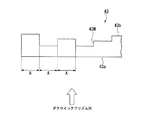
偏光変換板(偏光変換部)90は、図14に示すように、ポリカーボネートからなる基材91に複数の凹部91aが形成されている。基材91の厚みをtとすると、t>λ/(2・△n)であり、λ/2以上の位相差を得ることができるようにする。
凹部91aの形成方法としては、隣接する領域Aの厚みの最大の差dがλ/2の位相差、すなわち、d(max)=Re(max)/△n=λ/(2・△n)となるように、基材91の表面91bに領域Aごとに開口率(開口部93の大きさ)及び透過率(開口部93を透過する光線の割合)が異なるマスク92を用いる。そして、基材91の表面91bにレジストを塗布し、基材91と対向するマスク92の面92aと反対の面92bから光線を照射し、レジストをパターニングする。その後、エッチング処理を施すことにより、凹部91aが形成される。
[Seventh Embodiment]
Next, a seventh embodiment according to the present invention will be described with reference to FIG.
In the projector according to the present embodiment, a method for forming a polarization conversion plate by photolithography and etching will be described. In the present embodiment, the
As shown in FIG. 14, the polarization conversion plate (polarization conversion section) 90 has a plurality of
As a method for forming the
本実施形態では、マスク92の開口部93の大きさ及び透過率を変えることにより、所望の深さを有する凹部91aを形成することができる。すなわち、第6実施形態のサンドブラスト処理に比べて、設計通りに基材91を加工することが可能となる。さらに、マスク92の開口部93の大きさ及び透過率を変えることにより、凹部91aのパターンをより複雑に形成することも可能となる。
また、エッチング処理の方法は、ドライエッチングでもウェットエッチングでも良い。また、透過率変調マスク(面積階調を含む)を用いることにより、レジスト残膜量を自由に変更することができるため、エッチングの深さを自由に変更することが可能である。すなわち、偏光変換板90を所望の位相差に調整することも容易に可能となる。
また、凹部91aのパターニングに用いるマスク92は、メタルマスクを用いて直接加工しても良い。
In the present embodiment, by changing the size and transmittance of the
Further, the etching method may be dry etching or wet etching. Further, since the resist residual film amount can be freely changed by using a transmittance modulation mask (including area gradation), the etching depth can be freely changed. That is, the
Further, the
なお、本発明の技術範囲は上記実施形態に限定されるものではなく、本発明の趣旨を逸脱しない範囲において種々の変更を加えることが可能である。
例えば、色光合成手段として、ダイクロイックプリズムを用いたが、これに限るものではない。色光合成手段としては、例えば、ダイクロイックミラーをクロス配置とし色光を合成するもの、ダイクロイックミラーを平行に配置し色光を合成するものを用いることができる。
また、照明装置、たとえば、レーザ加工機、レーザ露光機に用いる偏光変換部として、第1実施形態の偏光変換部に限らず、第2〜第7実施形態のいずれの偏光変換部及び光拡散部を用いても良い。
また、液晶ライトバルブを備えずに、例えば、画像情報を含むスライド(ポジフィルム)の面を照明装置で照明し、スクリーン上に画像情報を含む光を投射する、所謂スライドプロジェクタに、上述の実施形態の照明装置を適用することも可能である。
The technical scope of the present invention is not limited to the above embodiment, and various modifications can be made without departing from the spirit of the present invention.
For example, although the dichroic prism is used as the color light combining means, the present invention is not limited to this. As the color light synthesizing means, for example, a dichroic mirror having a cross arrangement to synthesize color light, or a dichroic mirror arranged in parallel to synthesize color light can be used.
Further, the polarization conversion unit used in the illumination device, for example, a laser processing machine or a laser exposure machine, is not limited to the polarization conversion unit of the first embodiment, and any of the polarization conversion unit and the light diffusion unit of the second to seventh embodiments. May be used.
Further, for example, the above-described implementation is applied to a so-called slide projector that does not include a liquid crystal light valve and illuminates the surface of a slide (positive film) including image information with a lighting device and projects light including image information on a screen. It is also possible to apply a lighting device of the form.
T…中間像、1,60,70…プロジェクタ(画像表示装置)、10…光源装置(レーザ光源)、20…液晶ライトバルブ(光変調装置)、40,65…投射装置(投射手段)、43,51,80,90…偏光変換板(偏光変換部)、43M,72M,76M,81a,91a…凹部、50…スクリーン(被投射面)、52…光拡散板(光拡散部)、64…反射型ライトバルブ(反射型光変調装置)、72,76,81,91…基材、73,77…偏光変換部、74,78…光拡散部、75…ディフューザ(偏光変換拡散部材)
T ...
Claims (23)
該レーザ光源から射出されたレーザ光を複数種の偏光方向に変換して射出させる複数の領域を有する偏光変換部とを備え、
前記レーザ光源から射出されたレーザ光、あるいは、前記偏光変換部から射出されたレーザ光を拡散させ被投射面を照明することを特徴とする照明装置。 A laser light source for emitting laser light;
A polarization conversion unit having a plurality of regions for converting the laser light emitted from the laser light source into a plurality of types of polarization directions and emitting the same.
An illuminating device that illuminates a projection surface by diffusing laser light emitted from the laser light source or laser light emitted from the polarization converter.
該レーザ光源から射出されたレーザ光を複数種の偏光方向に変換して射出させる複数の領域を有する偏光変換部と、
前記レーザ光源から射出されたレーザ光を画像信号に応じて変調する光変調装置と、
該光変調装置により変調されたレーザ光を被投射面に投射する投射手段とを備え、
前記レーザ光源から射出されたレーザ光を拡散させ前記被投射面を照射することを特徴とする画像表示装置。 A laser light source for emitting laser light;
A polarization conversion unit having a plurality of regions for converting the laser light emitted from the laser light source into a plurality of types of polarization directions and emitting the light;
A light modulation device that modulates laser light emitted from the laser light source according to an image signal;
Projecting means for projecting the laser light modulated by the light modulation device onto the projection surface;
An image display device characterized by diffusing laser light emitted from the laser light source to irradiate the projection surface.
前記レーザ光源から射出されたレーザ光を拡散させる光拡散部を備えることを特徴とする請求項3に記載の画像表示装置。 A concave portion is formed in the polarization converter,
The image display apparatus according to claim 3, further comprising a light diffusion unit that diffuses laser light emitted from the laser light source.
少なくとも前記光拡散部が、前記光変調装置から射出されたレーザ光により中間像が形成される位置に配置されていることを特徴とする請求項5に記載の画像表示装置。 The polarization conversion unit and the light diffusion unit are disposed on an optical path between the light modulation device and the projection surface,
The image display device according to claim 5, wherein at least the light diffusing unit is disposed at a position where an intermediate image is formed by the laser light emitted from the light modulation device.
前記中間像形成光学系により前記中間像が形成されることを特徴とする請求項6に記載の画像表示装置。 An intermediate image forming optical system is disposed on the optical path between the light modulation device and the light diffusion unit,
The image display apparatus according to claim 6, wherein the intermediate image is formed by the intermediate image forming optical system.
前記光変調装置が、反射型光変調装置であることを特徴とする請求項5に記載の画像表示装置。 The polarization conversion unit and the light diffusion unit are disposed on an optical path between the light source and the light modulation device;
The image display device according to claim 5, wherein the light modulation device is a reflective light modulation device.
前記偏光変換部が、前記液晶素子と前記被投射面との間の光路上に配置され、
前記光拡散部が、前記光源と前記液晶素子との間の光路上に配置されていることを特徴とする請求項13に記載の画像表示装置。 The light modulation device is a transmissive liquid crystal element;
The polarization converter is disposed on an optical path between the liquid crystal element and the projection surface;
The image display device according to claim 13, wherein the light diffusing unit is disposed on an optical path between the light source and the liquid crystal element.
入射したレーザ光を拡散させる光拡散部とを備え、
基材の一方の面に前記偏光変換部が形成され、前記一方の面と反対の他方の面に前記光拡散部が形成され、
前記光拡散部が前記他方の面に2つの光を干渉させることにより形成されることを特徴とする偏光変換拡散部材。 A polarization conversion section having a plurality of regions for converting incident laser light into a plurality of types of polarization directions and emitting the same; and
A light diffusing section for diffusing the incident laser light,
The polarization conversion part is formed on one surface of the substrate, and the light diffusion part is formed on the other surface opposite to the one surface,
The polarization conversion diffusion member, wherein the light diffusion portion is formed by causing two lights to interfere with the other surface.
入射したレーザ光を拡散させる光拡散部とを備え、
基材の一方の面に前記偏光変換部が形成され、前記一方の面と反対の他方の面に前記光拡散部が形成され、
前記光拡散部が回折素子であることを特徴とする偏光変換拡散部材。 A polarization conversion section having a plurality of regions for converting incident laser light into a plurality of types of polarization directions and emitting the same; and
A light diffusing section for diffusing the incident laser light,
The polarization conversion part is formed on one surface of the substrate, and the light diffusion part is formed on the other surface opposite to the one surface,
The polarization conversion diffusion member, wherein the light diffusion portion is a diffraction element.
Priority Applications (2)
| Application Number | Priority Date | Filing Date | Title |
|---|---|---|---|
| JP2007330805A JP2009151221A (en) | 2007-12-21 | 2007-12-21 | Illuminator, image display apparatus, and polarization conversion/diffusion member |
| US12/255,172 US8469515B2 (en) | 2007-12-21 | 2008-10-21 | Illuminator, image display apparatus, and polarization conversion/diffusion member |
Applications Claiming Priority (1)
| Application Number | Priority Date | Filing Date | Title |
|---|---|---|---|
| JP2007330805A JP2009151221A (en) | 2007-12-21 | 2007-12-21 | Illuminator, image display apparatus, and polarization conversion/diffusion member |
Related Child Applications (1)
| Application Number | Title | Priority Date | Filing Date |
|---|---|---|---|
| JP2012195829A Division JP5429343B2 (en) | 2012-09-06 | 2012-09-06 | Image display device |
Publications (2)
| Publication Number | Publication Date |
|---|---|
| JP2009151221A true JP2009151221A (en) | 2009-07-09 |
| JP2009151221A5 JP2009151221A5 (en) | 2011-01-27 |
Family
ID=40788196
Family Applications (1)
| Application Number | Title | Priority Date | Filing Date |
|---|---|---|---|
| JP2007330805A Pending JP2009151221A (en) | 2007-12-21 | 2007-12-21 | Illuminator, image display apparatus, and polarization conversion/diffusion member |
Country Status (2)
| Country | Link |
|---|---|
| US (1) | US8469515B2 (en) |
| JP (1) | JP2009151221A (en) |
Cited By (13)
| Publication number | Priority date | Publication date | Assignee | Title |
|---|---|---|---|---|
| JPH0932174A (en) * | 1995-07-14 | 1997-02-04 | Ando Corp | Half-precast concrete board and slab structure and wall structure using the concrete board |
| JP2011197594A (en) * | 2010-03-24 | 2011-10-06 | Casio Computer Co Ltd | Light emitting unit and projector |
| WO2012027906A1 (en) * | 2010-09-03 | 2012-03-08 | 青岛海信信芯科技有限公司 | Optical rotator and laser speckle suppression divece and method based on the same |
| JP2012078807A (en) * | 2010-09-08 | 2012-04-19 | Asahi Glass Co Ltd | Projection type display device |
| JP2012194221A (en) * | 2011-03-15 | 2012-10-11 | Asahi Glass Co Ltd | Depolarization element and projection type display device |
| JP2013054167A (en) * | 2011-09-02 | 2013-03-21 | Seiko Epson Corp | Light source device and projector |
| JP2014163973A (en) * | 2013-02-21 | 2014-09-08 | Seiko Epson Corp | Illumination device and projector |
| WO2014208436A1 (en) * | 2013-06-25 | 2014-12-31 | 大日本印刷株式会社 | Projection device and projection-type display device |
| JP2015114628A (en) * | 2013-12-13 | 2015-06-22 | 大日本印刷株式会社 | Luminaire, projector and scanner |
| WO2015162767A1 (en) * | 2014-04-24 | 2015-10-29 | Necディスプレイソリューションズ株式会社 | Laser light source, projector provided with laser light source, and method for manufacturing laser light source |
| JP2016029488A (en) * | 2015-09-25 | 2016-03-03 | 大日本印刷株式会社 | Lighting device and light deflecting unit |
| JP2017182070A (en) * | 2017-04-12 | 2017-10-05 | 大日本印刷株式会社 | Projection device and projection display device |
| WO2019156203A1 (en) * | 2018-02-09 | 2019-08-15 | ウシオ電機株式会社 | Color image display device, color image duplicate creation method using same, and color image duplicate created thereby |
Families Citing this family (17)
| Publication number | Priority date | Publication date | Assignee | Title |
|---|---|---|---|---|
| US8059340B2 (en) * | 2007-08-01 | 2011-11-15 | Texas Instruments Incorporated | Method and system for reducing speckle by vibrating a line generating element |
| US8395714B2 (en) * | 2009-04-16 | 2013-03-12 | Microvision, Inc. | Scanned projection system using polymerized liquid crystal layer for speckle reduction |
| US8287128B2 (en) * | 2009-04-16 | 2012-10-16 | Microvision, Inc. | Laser projection source with polarization diversity element for speckle reduction |
| US8049825B2 (en) * | 2009-04-16 | 2011-11-01 | Microvision, Inc. | Laser projection source with birefringent wedge for speckle reduction |
| CN104614867B (en) * | 2010-09-03 | 2017-01-11 | 青岛海信电器股份有限公司 | Optical rotor and device and method for inhibiting laser speckle based on optical rotor |
| US9176365B2 (en) * | 2010-09-08 | 2015-11-03 | Dai Nippon Printing Co., Ltd. | Illumination device, projection device, and projection-type image display device |
| JP5403044B2 (en) | 2011-04-28 | 2014-01-29 | 大日本印刷株式会社 | Projection device and projection control device |
| JP5953835B2 (en) * | 2011-09-07 | 2016-07-20 | セイコーエプソン株式会社 | projector |
| JP5741341B2 (en) * | 2011-09-16 | 2015-07-01 | 大日本印刷株式会社 | Projection device and hologram recording medium |
| JP5984013B2 (en) * | 2011-12-27 | 2016-09-06 | ウシオ電機株式会社 | Coherent light source device and projector |
| JP2014002176A (en) * | 2012-06-15 | 2014-01-09 | Ushio Inc | Light source device and projector |
| CN116300285A (en) * | 2017-03-14 | 2023-06-23 | 快照公司 | Laser illumination system with reduced speckle |
| CN108761828B (en) * | 2018-06-25 | 2020-11-13 | 太原理工大学 | Special speckle eliminating light source for laser display |
| US11686971B2 (en) | 2020-01-19 | 2023-06-27 | 3M Innovative Properties Company | Article for display device and display system |
| CN112987472A (en) * | 2021-02-22 | 2021-06-18 | 青岛海信激光显示股份有限公司 | Multicolor light source and projection equipment |
| CN112987471A (en) * | 2021-02-22 | 2021-06-18 | 青岛海信激光显示股份有限公司 | Multicolor light source and projection apparatus |
| EP4402893A1 (en) * | 2021-10-18 | 2024-07-24 | DigiLens Inc. | Compact projector for display system |
Citations (3)
| Publication number | Priority date | Publication date | Assignee | Title |
|---|---|---|---|---|
| JP2002090881A (en) * | 2000-09-20 | 2002-03-27 | Seiko Epson Corp | Projector device and image quality improving mechanism |
| WO2005062114A1 (en) * | 2003-12-24 | 2005-07-07 | Matsushita Electric Industrial Co., Ltd. | 2-dimensional image display device |
| JP2007279204A (en) * | 2006-04-04 | 2007-10-25 | Seiko Epson Corp | Projector |
Family Cites Families (12)
| Publication number | Priority date | Publication date | Assignee | Title |
|---|---|---|---|---|
| US5313479A (en) | 1992-07-29 | 1994-05-17 | Texas Instruments Incorporated | Speckle-free display system using coherent light |
| US7023602B2 (en) * | 1999-05-17 | 2006-04-04 | 3M Innovative Properties Company | Reflective LCD projection system using wide-angle Cartesian polarizing beam splitter and color separation and recombination prisms |
| JPH11249010A (en) * | 1998-02-27 | 1999-09-17 | Minolta Co Ltd | Projector optical system |
| US7152977B2 (en) * | 2003-04-24 | 2006-12-26 | Qubic Light Corporation | Solid state light engine optical system |
| US7271962B2 (en) * | 2003-07-22 | 2007-09-18 | Matsushita Electric Industrial Co., Ltd. | Two-dimensional image formation apparatus |
| JP4534453B2 (en) | 2003-09-04 | 2010-09-01 | ソニー株式会社 | Projection type image display device |
| US7399084B2 (en) * | 2004-04-09 | 2008-07-15 | Matsushita Electric Industrial Co., Ltd. | Laser image display apparatus |
| US7320521B2 (en) * | 2004-07-12 | 2008-01-22 | Next Wave Optics, Inc. | Optical engine architectures |
| JP2006047421A (en) * | 2004-07-30 | 2006-02-16 | Canon Inc | Display optical system and image projection apparatus |
| JP4182032B2 (en) * | 2004-07-30 | 2008-11-19 | キヤノン株式会社 | Display optical system and image projection apparatus |
| JP4290095B2 (en) | 2004-08-16 | 2009-07-01 | キヤノン株式会社 | Display optical system and image display system |
| JP4903711B2 (en) * | 2004-10-22 | 2012-03-28 | コーニンクレッカ フィリップス エレクトロニクス エヌ ヴィ | Projection system |
-
2007
- 2007-12-21 JP JP2007330805A patent/JP2009151221A/en active Pending
-
2008
- 2008-10-21 US US12/255,172 patent/US8469515B2/en not_active Expired - Fee Related
Patent Citations (3)
| Publication number | Priority date | Publication date | Assignee | Title |
|---|---|---|---|---|
| JP2002090881A (en) * | 2000-09-20 | 2002-03-27 | Seiko Epson Corp | Projector device and image quality improving mechanism |
| WO2005062114A1 (en) * | 2003-12-24 | 2005-07-07 | Matsushita Electric Industrial Co., Ltd. | 2-dimensional image display device |
| JP2007279204A (en) * | 2006-04-04 | 2007-10-25 | Seiko Epson Corp | Projector |
Non-Patent Citations (1)
| Title |
|---|
| JPN6012053873; 土井康弘: 光学技術シリーズ4 偏光と結晶光学 , 19751205, 第14頁ないし第23頁, 共立出版株式会社 * |
Cited By (20)
| Publication number | Priority date | Publication date | Assignee | Title |
|---|---|---|---|---|
| JPH0932174A (en) * | 1995-07-14 | 1997-02-04 | Ando Corp | Half-precast concrete board and slab structure and wall structure using the concrete board |
| JP2011197594A (en) * | 2010-03-24 | 2011-10-06 | Casio Computer Co Ltd | Light emitting unit and projector |
| WO2012027906A1 (en) * | 2010-09-03 | 2012-03-08 | 青岛海信信芯科技有限公司 | Optical rotator and laser speckle suppression divece and method based on the same |
| CN103052899A (en) * | 2010-09-03 | 2013-04-17 | 青岛海信电器股份有限公司 | Optical rotator and laser speckle suppression divece and method based on the same |
| JP2012078807A (en) * | 2010-09-08 | 2012-04-19 | Asahi Glass Co Ltd | Projection type display device |
| JP2012194221A (en) * | 2011-03-15 | 2012-10-11 | Asahi Glass Co Ltd | Depolarization element and projection type display device |
| US8696134B2 (en) | 2011-03-15 | 2014-04-15 | Asahi Glass Company, Limited | Depolarization element and projection type display device |
| JP2013054167A (en) * | 2011-09-02 | 2013-03-21 | Seiko Epson Corp | Light source device and projector |
| JP2014163973A (en) * | 2013-02-21 | 2014-09-08 | Seiko Epson Corp | Illumination device and projector |
| JP2015007715A (en) * | 2013-06-25 | 2015-01-15 | 大日本印刷株式会社 | Projection device and projection type display device |
| WO2014208436A1 (en) * | 2013-06-25 | 2014-12-31 | 大日本印刷株式会社 | Projection device and projection-type display device |
| US9641828B2 (en) | 2013-06-25 | 2017-05-02 | Dai Nippon Printing Co., Ltd. | Projector and projection display device |
| US10075698B2 (en) | 2013-06-25 | 2018-09-11 | Dai Nippon Printing Co., Ltd. | Projector and projection display device |
| JP2015114628A (en) * | 2013-12-13 | 2015-06-22 | 大日本印刷株式会社 | Luminaire, projector and scanner |
| WO2015162767A1 (en) * | 2014-04-24 | 2015-10-29 | Necディスプレイソリューションズ株式会社 | Laser light source, projector provided with laser light source, and method for manufacturing laser light source |
| US9882345B2 (en) | 2014-04-24 | 2018-01-30 | Nec Display Solutions, Ltd. | Laser light source, projector provided with laser light source, and method for manufacturing laser light source |
| JP2016029488A (en) * | 2015-09-25 | 2016-03-03 | 大日本印刷株式会社 | Lighting device and light deflecting unit |
| JP2017182070A (en) * | 2017-04-12 | 2017-10-05 | 大日本印刷株式会社 | Projection device and projection display device |
| WO2019156203A1 (en) * | 2018-02-09 | 2019-08-15 | ウシオ電機株式会社 | Color image display device, color image duplicate creation method using same, and color image duplicate created thereby |
| JPWO2019156203A1 (en) * | 2018-02-09 | 2020-02-27 | ウシオ電機株式会社 | Color image display device, color image duplicate creation method using the same, and color image duplicate created by the method |
Also Published As
| Publication number | Publication date |
|---|---|
| US20090161072A1 (en) | 2009-06-25 |
| US8469515B2 (en) | 2013-06-25 |
Similar Documents
| Publication | Publication Date | Title |
|---|---|---|
| JP2009151221A (en) | Illuminator, image display apparatus, and polarization conversion/diffusion member | |
| US10809541B2 (en) | Projection device and projection-type video display device | |
| US10228573B2 (en) | Projection device and projection-type video display device | |
| JP4158987B2 (en) | Two-dimensional image forming apparatus | |
| JP4475302B2 (en) | Projector and projection device | |
| JP4407585B2 (en) | LIGHTING DEVICE, IMAGE DISPLAY DEVICE, AND PROJECTOR | |
| JP4449848B2 (en) | LIGHTING DEVICE, IMAGE DISPLAY DEVICE, AND PROJECTOR | |
| CN101276198A (en) | Illumination device and method for illuminating uniformly an image generating micro display | |
| JP4367394B2 (en) | Image display device and projector | |
| JP2010160307A (en) | Optical element and image display device | |
| EP2645404B1 (en) | Exposure apparatus | |
| WO2012141254A1 (en) | Illumination device, projection device, and projection-type image display device | |
| JP2009042373A (en) | Projector | |
| JP5429343B2 (en) | Image display device | |
| JP6598100B2 (en) | Illumination device, projection device, and projection-type image display device | |
| JP6229928B2 (en) | Illumination device and projection device | |
| JP2015155950A (en) | Illumination device and projection device | |
| JP6287157B2 (en) | Illumination device and projection device |
Legal Events
| Date | Code | Title | Description |
|---|---|---|---|
| A521 | Written amendment |
Free format text: JAPANESE INTERMEDIATE CODE: A523 Effective date: 20101203 |
|
| A621 | Written request for application examination |
Free format text: JAPANESE INTERMEDIATE CODE: A621 Effective date: 20101203 |
|
| A521 | Written amendment |
Free format text: JAPANESE INTERMEDIATE CODE: A821 Effective date: 20101206 |
|
| RD04 | Notification of resignation of power of attorney |
Free format text: JAPANESE INTERMEDIATE CODE: A7424 Effective date: 20120124 |
|
| A977 | Report on retrieval |
Free format text: JAPANESE INTERMEDIATE CODE: A971007 Effective date: 20120305 |
|
| A131 | Notification of reasons for refusal |
Free format text: JAPANESE INTERMEDIATE CODE: A131 Effective date: 20120724 |
|
| A521 | Written amendment |
Free format text: JAPANESE INTERMEDIATE CODE: A523 Effective date: 20120912 |
|
| A131 | Notification of reasons for refusal |
Free format text: JAPANESE INTERMEDIATE CODE: A131 Effective date: 20121016 |
|
| A521 | Written amendment |
Free format text: JAPANESE INTERMEDIATE CODE: A523 Effective date: 20121211 |
|
| A02 | Decision of refusal |
Free format text: JAPANESE INTERMEDIATE CODE: A02 Effective date: 20130108 |