JP2009148928A - Liquid jetting apparatus - Google Patents
Liquid jetting apparatus Download PDFInfo
- Publication number
- JP2009148928A JP2009148928A JP2007327170A JP2007327170A JP2009148928A JP 2009148928 A JP2009148928 A JP 2009148928A JP 2007327170 A JP2007327170 A JP 2007327170A JP 2007327170 A JP2007327170 A JP 2007327170A JP 2009148928 A JP2009148928 A JP 2009148928A
- Authority
- JP
- Japan
- Prior art keywords
- liquid
- ink
- meniscus
- ejection
- liquid ejecting
- Prior art date
- Legal status (The legal status is an assumption and is not a legal conclusion. Google has not performed a legal analysis and makes no representation as to the accuracy of the status listed.)
- Withdrawn
Links
Images


Landscapes
- Ink Jet (AREA)
- Particle Formation And Scattering Control In Inkjet Printers (AREA)
Abstract
Description
本発明は、液体噴射装置に関するものである。 The present invention relates to a liquid ejecting apparatus.
従来、液体噴射装置として記録ヘッド(液体噴射ヘッド)の噴射口より記録媒体にインク(液体)を噴射するインクジェット式プリンタ(以下、プリンタと称す)が知られている。ところで、このようなインクジェット式のプリンタでは、インクの吐出特性を保持すべく、噴射口内のメニスカスを良好な状態に保つ必要がある。そこで、インクジェット法を用いてカラーフィルタを製造する際に、メニスカスを振動させることでインクの安定吐出を図った技術がある(例えば、特許文献1参照)。また、このようなプリンタでは、通常、記録ヘッドの噴射特性を維持或いは回復させるためのクリーニング処理として、例えばフラッシング処理が行われる。
しかしながら、インク中に比較的大きな気泡が含まれている場合、上述したようなフラッシング処理やメニスカスの振動では気泡を排出することができない。そのため、インク内に残留した気泡により、インクの吐出不良が引き起こされる可能性があった。 However, when relatively large bubbles are contained in the ink, the bubbles cannot be discharged by the above-described flushing process or meniscus vibration. Therefore, there is a possibility that ink ejection failure may be caused by bubbles remaining in the ink.
本発明はこのような事情に鑑みてなされたものであって、液体中に含まれる大きな気泡に起因する吐出不良の発生を防止することのできる、液体噴射装置を提供することを目的としている。 The present invention has been made in view of such circumstances, and an object thereof is to provide a liquid ejecting apparatus that can prevent the occurrence of ejection failure due to large bubbles contained in a liquid.
上記課題を解決するために、本発明の液体噴射装置は、液体を噴射する複数の噴射口が形成された噴射口形成面を有する記録ヘッドと、前記液体のメニスカスを生成するメニスカス生成装置と、を備える液体噴射装置であって、前記メニスカス生成装置は、前記液体を前記噴射口から噴射させることなく前記噴射口形成面側に押し出す動作と、前記液体を前記噴射口内に引き込む動作とを繰り返し、前記メニスカスを生成することを特徴とする。 In order to solve the above problems, a liquid ejecting apparatus of the present invention includes a recording head having an ejection port forming surface on which a plurality of ejection ports for ejecting liquid are formed, a meniscus generating device that generates a meniscus of the liquid, The meniscus generator repeats an operation of pushing out the liquid to the ejection port forming surface side without ejecting the liquid from the ejection port, and an operation of drawing the liquid into the ejection port. The meniscus is generated.
本発明の液体噴射装置によれば、例えば噴射口内に比較的大きな気泡が含まれていた場合、押し出し動作及び引き込み動作が繰り返されることで、気泡が噴射口形成面側に排出させると共にメニスカスを生成することが可能となる。よって、液体中に大きな気泡が含有されていた場合でも、良好なメニスカスを噴射口内に生成できる。
したがって、大きな気泡に起因する液体の噴射不良の発生が防止された吐出特性の高い液体噴射装置を提供できる。
According to the liquid ejecting apparatus of the present invention, for example, when a relatively large bubble is contained in the ejection port, the extrusion operation and the drawing operation are repeated, so that the bubble is discharged to the ejection port forming surface side and a meniscus is generated. It becomes possible to do. Therefore, even when large bubbles are contained in the liquid, a good meniscus can be generated in the injection port.
Accordingly, it is possible to provide a liquid ejecting apparatus having high ejection characteristics in which occurrence of defective liquid ejection due to large bubbles is prevented.
また、上記液体噴射装置においては、前記液体を貯留する液体貯留部及び前記液体噴射ヘッド間を接続する液体流路を有し、該液体流路に前記メニスカス生成手段が設けられるのが好ましい。
この構成によれば、液体噴射ヘッドと液体貯留部とが例えばチューブ等の流体流路で接続された、所謂オフキャリッジタイプの液体噴射装置に本発明を適用可能となる。
このとき、前記記録ヘッドは、周期的な加圧を行うことで前記噴射口から前記液体を噴射させる液体噴射手段を含み、前記メニスカス生成装置は、前記液体流路内の前記液体を前記液体噴射手段に比べて振幅が大きく且つ低い周波数で脈動させることにより前記押し出し動作及び引き込み動作を行うのがより好ましい。
このようにすれば、メニスカス生成装置は、液体噴射装置に対して振幅が大きく、低周波数の振動を液体に付与することが可能とされ、インク内に含まれる大きな気泡を上述したように良好に排出できる。
さらに、前記メニスカス生成装置が電動シリンジにより構成されるのが望ましい。このようにすれば、上述したような振幅の大きな低周波の振動を液体に良好に付与することができ、気泡の排出性を向上できる。
In the liquid ejecting apparatus, it is preferable that the liquid storing unit that stores the liquid and a liquid channel that connects the liquid ejecting heads are provided, and the meniscus generating unit is provided in the liquid channel.
According to this configuration, the present invention can be applied to a so-called off-carriage type liquid ejecting apparatus in which the liquid ejecting head and the liquid storage portion are connected by a fluid flow path such as a tube.
At this time, the recording head includes a liquid ejecting unit that ejects the liquid from the ejection port by performing periodic pressurization, and the meniscus generating device ejects the liquid in the liquid channel. More preferably, the push-out operation and the pull-in operation are performed by pulsating at a low frequency with a larger amplitude than that of the means.
In this way, the meniscus generating apparatus has a larger amplitude than the liquid ejecting apparatus and can apply low-frequency vibration to the liquid, and the large bubbles contained in the ink can be satisfactorily as described above. Can be discharged.
Furthermore, it is desirable that the meniscus generating device is constituted by an electric syringe. In this way, the low-frequency vibration having a large amplitude as described above can be favorably applied to the liquid, and the bubble discharge performance can be improved.
また、上記液体噴射装置においては、前記メニスカスの生成後、前記噴射口形成面を払拭するワイピング動作を実行するワイピング機構を備えるのが好ましい。
この構成によれば、メニスカス生成装置により噴射口形成面上に付着した気泡を拭き取ることが可能となる。よって、噴射口内の液体中に、再度気泡が入り込んでしまうといった不具合を防止できる。
The liquid ejecting apparatus preferably includes a wiping mechanism that performs a wiping operation of wiping the ejection port forming surface after the meniscus is generated.
According to this configuration, it is possible to wipe off air bubbles adhering to the injection port forming surface by the meniscus generating device. Therefore, it is possible to prevent a problem that bubbles enter the liquid in the injection port again.
また、上記液体噴射装置においては、前記メニスカス生成装置は、前記液体の押し込み動作及び引き込み動作を行うと共に、前記メニスカスを微振動させるのが好ましい。
この構成によれば、押し込み動作及び引き込み動作に加えてメニスカスに微振動が加えられるので、液体中の微小な気泡を噴射口形成基板側に排出させると共に、液体内部に攪拌し溶解させることができる。よって、微小気泡が除去されることで、液体の噴射特性をより向上させることができる。
In the liquid ejecting apparatus, it is preferable that the meniscus generating device performs a pushing operation and a drawing operation of the liquid and slightly vibrates the meniscus.
According to this configuration, since the meniscus is slightly vibrated in addition to the pushing operation and the drawing operation, minute bubbles in the liquid can be discharged to the injection port forming substrate side, and can be stirred and dissolved in the liquid. . Therefore, the liquid ejection characteristics can be further improved by removing the microbubbles.
以下、本発明に係る液体噴射装置の実施形態について、図を参照して説明する。なお、以下の図面において、各部材を認識可能な大きさとするために、各部材の縮尺を適宜変更している。 Hereinafter, an embodiment of a liquid ejecting apparatus according to the invention will be described with reference to the drawings. In the following drawings, the scale of each member is appropriately changed in order to make each member a recognizable size.
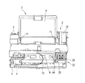
図1は、本実施形態に係る液体噴射装置の一例を示す斜視図、図2は、平面図である。
本実施形態に係る液体噴射装置は、インク等の流体を噴射する液体噴射装置である。液体噴射装置の一例として、記録ヘッドの噴射口から記録媒体にインクを噴射して、その記録媒体に対する記録を実行するインクジェット式プリンタを用いて説明する。なお、以下の説明では、そのインクジェット式記録装置の一例として、記録媒体である記録紙にインクの滴を吐出(噴射)して、その記録紙に対する記録を実行するインクジェットプリンタについて説明する。
FIG. 1 is a perspective view illustrating an example of a liquid ejecting apparatus according to the present embodiment, and FIG. 2 is a plan view.
The liquid ejecting apparatus according to the present embodiment is a liquid ejecting apparatus that ejects a fluid such as ink. As an example of a liquid ejecting apparatus, description will be made using an ink jet printer that ejects ink onto a recording medium from an ejection port of a recording head and executes recording on the recording medium. In the following description, as an example of the ink jet recording apparatus, an ink jet printer that discharges (injects) ink droplets onto a recording paper that is a recording medium and performs recording on the recording paper will be described.
図1及び図2に示すように、インクジェットプリンタ1は、インクにより記録紙に対する記録を実行する記録ユニット2と、記録紙を搬送する記録紙搬送機構3とを備えている。
記録ユニット2は、インクを噴射する記録ヘッド4(噴射ヘッド)と、記録ヘッド4を支持しながら移動可能なキャリッジ5と、記録ヘッド4及びキャリッジ5と対向する位置に配置され、インクが噴射される記録紙を支持するプラテン6とを含む。
As shown in FIGS. 1 and 2, the
The recording unit 2 is disposed at a position facing the
インクジェットプリンタ1は、キャリッジ5を移動するモータ等を含むキャリッジ駆動装置7と、キャリッジ5の移動を案内するキャリッジガイド部材とを備えている。
キャリッジ5は、キャリッジガイド部材に案内されながら、キャリッジ駆動装置7によって、主走査方向に移動する。記録紙は、記録紙搬送機構3により、記録ユニット2に対して、主走査方向と交差する副走査方向に移動する。
The
The
また、インクジェットプリンタ1は、記録紙を収容する給紙カセット9を備えている。
給紙カセット9は、インクジェットプリンタ1の本体の背面側に、着脱可能に設けられている。給紙カセット9は、積層された複数の記録紙を収容可能に設けられている。
The
The paper feed cassette 9 is detachably provided on the back side of the main body of the
記録紙搬送機構3は、給紙カセット9の記録紙を搬出するための給紙ローラと、給紙ローラを駆動するモータ等を含む給紙ローラ駆動装置10と、記録紙の移動を案内する記録紙ガイド部材11と、給紙ローラに対して搬送方向の下流側に配置されている搬送ローラと、搬送ローラを駆動する搬送ローラ駆動装置と、記録ユニット2に対して搬送方向の下流側に配置されている排出ローラとを有している。
The recording
給紙ローラは、給紙カセット9に積層されている複数の記録紙のうち、最も上側に配置されている記録紙をピックアップし、給紙カセット9より搬出可能に構成されている。給紙カセット9の記録紙は、記録紙ガイド部材11に案内されながら、給紙ローラ駆動装置10によって駆動する給紙ローラによって、搬送ローラに送られる。搬送ローラに送られた記録紙は、搬送ローラ駆動装置によって駆動する搬送ローラにより、搬送方向の下流側に配置された記録ユニット2に搬送される。
The paper feed roller is configured to pick up the recording paper arranged on the uppermost side among the plurality of recording papers stacked in the paper feed cassette 9 and to carry it out of the paper feed cassette 9. The recording paper in the paper feeding cassette 9 is fed to the conveying roller by the paper feeding roller driven by the paper feeding
記録ユニット2のプラテン6は、記録ヘッド4及びキャリッジ5と対向する位置に配置され、記録紙の下面を支持する。記録ヘッド4及びキャリッジ5は、プラテン6の上方に配置されている。記録紙搬送機構3は、記録ユニット2による記録動作と連動して、記録紙を副走査方向に搬送する。記録ユニット2で記録された記録紙は、排出ローラを含む記録紙搬送機構3によって、インクジェットプリンタ1の正面側から排出される。
The
また、インクジェットプリンタ1は、インクカートリッジのインクをキャリッジ5の記録ヘッド4に供給するインク供給チューブ12を備えている。インクカートリッジのインクは、インク供給針を介してインク供給路に供給され、そのインク供給路より、インク供給チューブ12を介して、キャリッジ5の記録ヘッド4に供給される。
また、インクジェットプリンタ1は、記録ヘッド4をメンテナンス可能なメンテナンス装置13を備えている。
The
The
メンテナンス装置13は、キャッピング装置14及びワイピング装置15を含む。ワイピング装置15は、記録ヘッド4と対向可能であり、記録ヘッド4の吐出口形成面17を払拭可能なワイプ部材44を備えている。ワイピング装置15は、ワイプ部材44を用いて、残留したインク等、記録ヘッド4の吐出口形成面17(後述)に付着している異物を拭き取ったり、払ったりすることができる。
The
メンテナンス装置13は、キャリッジ5及び記録ヘッド4のホームポジションに配置されている。ホームポジションは、キャリッジ5の移動領域内であって、記録ユニット2による記録動作が実行される記録領域の外側の端部領域に設定されている。電源が切断されている間、あるいは長時間に亘って記録動作が実行されない場合、キャリッジ5及び記録ヘッド4は、ホームポジションに配置される。
The
図3は、インクジェットプリンタ1におけるインクの供給経路を説明するための模式図である。図3に示されるように、インクジェットプリンタ1は、インク供給チューブ12を有し、このインクカートリッジ48からインク供給チューブ12を介して供給されるインクLが記録ヘッド4内に流入する。
FIG. 3 is a schematic diagram for explaining an ink supply path in the
インク供給チューブ12は、インクカートリッジ48と、記録ヘッド4に接続されたサブタンク(自己封止バルブ)51とを接続しており、インクカートリッジ48からインク供給チューブ12を介してサブタンク51にインクが供給されるようになっている。
The
インクカートリッジ48は、ケース部材49と、ケース部材49に収容され、可塑性材料で形成されたインクパック50とを含む。また、ケース部材49には不図示の検出装置が接続されており、インクカートリッジ48の交換時期を検出可能となっている。
The
サブタンク51は、例えばポリプロピレン等の樹脂製材料によって成型される。このサブタンク51には、インク室52となる凹部が形成され、この凹部の開口面に透明な弾性シートを貼設してインク室52が区画されている。このサブタンク51には、インク室52に連通する連通溝部53′を有する延出部53が形成されており、この延出部53の上面にはインク流入口54が突設されている。このインク流入口54には、インクカートリッジ48に貯留されたインクLを供給する上記インク供給チューブ12が接続される。したがって、インク供給チューブ12を通ってきたインクLは、このインク流入口54から連通溝部53′を通ってインク室52に流入するようになっている。
The
ところで、インクジェットプリンタ1は、記録ヘッド4とサブタンク51とを接続するインク供給チューブ12に、記録ヘッド4におけるインクのメニスカスを生成するメニスカス生成装置8が設けられている。このメニスカス生成装置8は、インクを吐出口(噴射口)16から吐出(噴射)させることなく、吐出口16が複数形成された吐出口形成面17側に押し出す動作と、インクを吐出口16内に引き込む動作とを繰り返し行い、メニスカスを生成可能となっている。なお、メニスカス生成装置8はインクジェットプリンタ1全体の動作を制御する制御装置58により駆動される。
In the
本実施形態においては、メニスカス生成装置8は電動シリンジにより構成されている。電気シリンジは、ピストン8aと、このピストン8aとの間で閉空間を構成するケース部8bとを備えている。ケース部8bは円筒形状から構成されており、その一端側が上記インク供給チューブ12に接続されている。本実施形態においては、ケース部8bの内径が0.1mm〜0.2mm程度に設定されており、上記ピストン8aのストロークが3〜15mm程度に設定される。
In the present embodiment, the
また、メニスカス調整装置8とインクカートリッジ48との間には、インク供給チューブ12を開閉可能とする流路バルブが設けられている。本実施形態では、インク供給チューブ12における、インクカートリッジ48及びサブタンク51間のインクカートリッジ48側に設けられた第一流路バルブB1と、サブタンク51及びメニスカス調整装置8間のサブタンク51側に設けられた第二流路バルブB2と、を備えている。
A flow path valve that can open and close the
インクジェットプリンタ1は、これら第一、第二流路バルブB1,B2の開閉動作をメニスカス調整装置8の動作に合わせて行うことで、インクカートリッジ48にインクが逆流するのを防止している。インクジェットプリンタ1は、インクの押し込み動作時において、第一流路バルブB1、及び第二流路バルブB2を開いた状態に保持する。また、インクの引き出し時において、インクジェットプリンタ1は、第一流路バルブB1、及び第二流路バルブB2を閉じた状態に保持する。このような構成により、ピストン8aが押し込まれるとピストン8aによってケース部8b内の空間が加圧され、インク供給チューブ12内が正圧状態となる。よって、インク供給チューブ12内のインクが加圧されることなり、インクメニスカスを吐出口16内から押し出すことが可能となる。一方、ピストン8bを引き込むとピストン8aによってケース部8b内の空間が減圧され、インク供給チューブ12内が負圧状態となる。よって、インク供給チューブ12内のインクがケース部8b内に引き込まれることとなり、インクメニスカスを吐出口16内に引き込ませることが可能となる。本実施形態においては、上述したように電動シリンジによりメニスカス生成装置8が構成されるため、上記制御装置58からの電気信号に基づいて精度良くメニスカスを生成することが可能となっている。
The
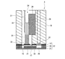
図4は、記録ヘッド4の断面図である。
図4に示すように、記録ヘッド4は、ヘッド本体18と、振動板19、流路基板20、及びノズル基板21を含む流路形成ユニット22とを備えている。吐出口形成面17は、ノズル基板21の下面によって形成されている。吐出口16は、ノズル基板21に形成されている。ここで、吐出口16の径は、用いられるインクに対応して、例えば、従来よりも約15%程度大きく形成されている。流路形成ユニット22は、振動板19、流路基板20、及びノズル基板21を積層し、接着剤等で接合して一体にしたものである。
FIG. 4 is a cross-sectional view of the
As shown in FIG. 4, the
記録ヘッド4は、ヘッド本体18の内部に形成された収容空間23と、収容空間23に配置された駆動ユニット24とを備えている。駆動ユニット24は、複数の圧電素子25と、圧電素子25の上端を支持する固定部材26と、駆動信号を圧電素子25に供給する柔軟なケーブル27とを備えている。圧電素子25は、複数の吐出口16のそれぞれに対応するように設けられている。
The
また、記録ヘッド4は、ヘッド本体18の内部に形成され、インクカートリッジからインク供給チューブ12を介して供給されたインクが流れる内部流路28と、振動板19、流路基板20、及びノズル基板21を含む流路形成ユニット22によって形成され、内部流路28と接続された共通インク室29と、流路形成ユニット22によって形成され、共通インク室29と接続されたインク供給口30と、流路形成ユニット22によって形成され、インク供給口30と接続された圧力室31とを備えている。圧力室31は、複数の吐出口16に対応するように複数設けられている。複数の吐出口16のそれぞれは、複数の圧力室31のそれぞれに接続されている。
In addition, the
ヘッド本体18は、合成樹脂で形成されている。振動板19は、例えばステンレス鋼等の金属製の支持板上に弾性フィルムをラミネート加工したものである。振動板19の圧力室31に対応する部分には、圧電素子25の下端と接合される島部32が形成されている。振動板19の少なくとも一部は、圧電素子25の駆動に応じて弾性変形する。振動板19と内部流路28の下端近傍との間にはコンプライアンス部33が形成されている。
The
流路基板20は、内部流路28の下端と吐出口16とを接続する共通インク室29、インク供給口30、及び圧力室31それぞれの空間を形成するための凹部を有する。本実施形態においては、流路基板20は、シリコンを異方性エッチングすることで形成されている。
The
ノズル基板21は、所定方向に所定間隔(ピッチ)で形成された複数の吐出口16を有する。本実施形態のノズル基板21は、例えばステンレス鋼等の金属で形成された板状の部材である。尚、上述のように吐出口形成面17は、ノズル基板21の下面によって形成されている。
The
インクジェットプリンタ1は、インクカートリッジ48からインク供給チューブ12を介して供給されたインクは上記内部流路28の上端に流入する。内部流路28の下端は、共通インク室29に接続されており、インクカートリッジからインク供給チューブ12を介して内部流路28の上端に流入したインクは、内部流路28を流れた後、共通インク室29に供給される。共通インク室29に供給されたインクは、インク供給口30を介して、複数の圧力室31のそれぞれに分配されるように供給される。
このように本実施形態に係るインクジェットプリンタ1は、所謂オフキャリッジタイプのプリンタとなっている。
In the
Thus, the
また、インクジェットプリンタ1は、ケーブル27を介して圧電素子25に駆動信号が入力されると、圧電素子25が伸縮する。これにより、振動板19が圧力室31に接近する方向及び離れる方向に変形(移動)する。これにより、圧力室31の容積が変化し、インクを収容した圧力室31の圧力が変動する。この圧力の変動によって、吐出口16から、インクが噴射(吐出)される。このように圧電素子25は、インクを噴射するための駆動信号に基づいて、吐出口16に接続された圧力室31の圧力を変動させる。
In the
図5は、インクジェットプリンタ1の電気的な構成を示すブロック図である。本実施形態におけるインクジェットプリンタ1は、インクジェットプリンタ1全体の動作を制御する上記制御装置58を備えている。この制御装置58には、インクジェットプリンタ1の動作に関する各種情報を入力する入力装置59と、インクジェットプリンタ1の動作に関する各種情報を記憶した記憶装置60とが接続されている。
FIG. 5 is a block diagram showing an electrical configuration of the
また、制御装置58には、上述した駆動装置7、記録紙搬送機構3、キャリッジ駆動装置7、キャッピング装置14及びワイピング装置15を含むメンテナンス装置13、及びメニスカス生成装置8等が接続されている。また、インクジェットプリンタ1は、圧電素子25を含む駆動ユニット24(図4参照)に入力する駆動信号を発生する駆動信号発生器62を備えている。この駆動信号発生器62は、制御装置58に接続されている。
駆動信号発生器62には、記録ヘッド4の圧電素子25に入力する吐出パルスの電圧値の変化量を示すデータ、及び吐出パルスの電圧を変化させるタイミングを規定するタイミング信号が入力される。駆動信号発生器62は、入力されたデータ及びタイミング信号に基づいて吐出パルス等の駆動信号を発生する。
The
The
駆動信号発生器62より吐出パルスが圧電素子25に入力されると、吐出口16よりインク滴が吐出される。吐出パルスが圧電素子25に入力されると、圧電素子25が収縮して圧力室31が膨張する。圧力室31の膨張状態が短時間維持された後、圧電素子25が急激に伸長する。これに伴って、圧力室31の容積が基準容積以下に収縮し、吐出口16に露出したメニスカスが外側に向けて急激に加圧される。これにより、所定量のインクの滴が吐出口16から吐出される。その後、インクの滴の吐出に伴うメニスカスの振動を短時間で収束させるように、圧力室31が基準容積に復帰する。すなわち、上記圧電素子25は周期的な加圧を行うことで吐出口16からインクを吐出させる液体噴射手段としての機能を有している。なお、圧電素子25の吐出パルスの周波数は、例えば50KHz程度に設定される。
When an ejection pulse is input from the
ところで、インクジェットプリンタ1は上記メンテナンス装置13を用いて、記録ヘッド4の噴射特性を維持するためのメンテナンス処理を実行可能である。メンテナンス処理は、噴射口16からインクをキャップ部材34に噴射するフラッシング動作、ワイピング装置15のワイプ部材44を用いたワイプ動作を含む。
By the way, the
本実施形態におけるインクジェットプリンタ1は、インクの噴射特性を維持すべく、インクを良好に吐出できない不良ノズルが発生した場合、或いは定期的なメンテナンス処理を行う場合に、制御装置58が上記メンテナンス装置13を駆動させてメンテナンス処理を実行させるようにしている。具体的に本実施形態では、インクジェットプリンタ1は、タイマークリーニングによって所定時間毎にフラッシング動作を実行するようにしている。フラッシング動作は、記録領域において吐出口16からのインクを記録紙に供給する前に、ホームポジションにおいて、吐出口16よりインクをキャップ部材34に予め噴射(吐出)する動作である。これにより、吐出口16付近の粘度が増大したインクが排出され、吐出口16の噴射特性が維持又は回復される。
In the
本実施形態におけるインクジェットプリンタ1は、上述したようにオフキャリッジタイプのプリンタであるため、インク内に気泡が多少混入した状態となる。この気泡は経時的に成長し、やがてインク内には比較的大きな気泡が混入された状態となる。上記フラッシング処理においては、増粘したインクは良好に外部に排出できるものの、インク中に含まれる大きな気泡を外部に排出することは難しい。
Since the
また、一般にフラッシング処理はインクのメニスカスを良好な形状に整える機能を兼ねている。しかしながら、上述したような大きな気泡がインク中に含まれている場合、メニスカス形状を整えることができず、結果的にインクを良好に吐出できない不良ノズルを生じさせ、インクの吐出特性が低下してしまう。したがって、フラッシング処理後のインクジェットプリンタ1において吐出不良が生じている場合、上述の気泡が要因となっているものとみなせる。
In general, the flushing process also has a function of adjusting the meniscus of the ink into a good shape. However, when large bubbles as described above are contained in the ink, the meniscus shape cannot be adjusted, resulting in defective nozzles that cannot eject ink well, and the ink ejection characteristics are reduced. End up. Therefore, when ejection failure occurs in the
一方、本実施形態に係るインクジェットプリンタ1は、上述したような問題を解消すべく、上記メニスカス生成装置8を備えている。ここで、メニスカス生成装置8の駆動方法を中心に、インクジェットプリンタ1の動作方法について図面を参照しながら説明する。
On the other hand, the
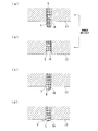
図6は、メニスカス生成装置8を用いた際のインクの動きを説明するための図である。
メニスカス生成装置8は、図6(a)に示されるようにインクLを吐出口16から吐出させることなく吐出口形成面17側に押し出す動作を行う。なお、インクL中には大きな気泡Kが混入している。さらに、メニスカス生成装置8は、図6(b)に示されるようにインクLを吐出口16内に引き込む動作を行う。メニスカス生成装置8は、これらインクLの押し出し動作及び引き込み動作を繰り返すようにしている。
FIG. 6 is a diagram for explaining the movement of ink when the
The
このとき、メニスカス生成装置8が、インク供給チューブ12内のインクを、上記圧電素子25における振動の周波数(50KHz)に比べて、振幅が大きく且つ低い周波数で脈動させることにより上記押し出し動作及び引き込み動作を行うようにしている。具体的には、メニスカス生成装置8においては、ピストン8aを移動させる周波数を0.2〜数Hz(例えば、3Hz)程度に設定し、ピストン8aを移動させるストロークを上述の3〜15mm程度に設定する。
At this time, the
このようにインクの押し出し動作及び引き込み動作を複数回繰り返すに従って、図6(c)に示されるようにインクL内に混入されている大きな気泡Kが吐出口形成面17側に押し出される。やがて、図6(d)に示されるように、インクL内に混入されていた大きな気泡Kは吐出口形成面17上に吐き出されることとなる。このようにメニスカス生成装置8によれば、フラッシング処理では排出することのできなかったインク中に混入した気泡を外部に排出すると共にメニスカスを生成することができる。よって、インク中に大きな気泡が混入していた場合でも、良好なメニスカスを吐出口16内に生成できる。
したがって、大きな気泡に起因する吐出不良が防止された信頼性の高い吐出特性を有したインクジェットプリンタ1を提供することができる。
In this way, as the ink pushing-out operation and the drawing-in operation are repeated a plurality of times, the large bubbles K mixed in the ink L are pushed out toward the ejection
Therefore, it is possible to provide the
このようにメニスカス生成装置8は、インクジェットプリンタ1に比べ、振幅が大きく、低周波数の振動をインクに付与することが可能とされることで、インクL内に含まれる大きな気泡Kを外部に良好に排出できる。
As described above, the
なお、押し出し動作及び引き込み動作における繰り返し回数は、インクL内から気泡が排出できる回数に設定される。すなわち、インクL内に混入している気泡の大きさ、シリンジ(メニスカス生成装置8)のピストン8aのストローク量によって適宜調整される。
The number of repetitions in the push-out operation and the pull-in operation is set to the number of times that bubbles can be discharged from the ink L. That is, it is appropriately adjusted according to the size of the bubbles mixed in the ink L and the stroke amount of the
本実施形態では、上記メニスカス生成装置8によりメニスカスを生成した後、上記ワイピング装置15のワイプ部材44により吐出口形成面17を払拭する。これにより、上記メニスカス生成装置8によって吐出口形成面17上に排出された気泡Kを拭き取ることができる。よって、吐出口16内のインクL中に、再度気泡が入り込んでしまうといった不具合を防止できる。
In this embodiment, after the meniscus is generated by the
また、インクL中には上述の大きな気泡Kに加え、大きな気泡に成長する前の微小な気泡も混入している。そこで、上記インクジェットプリンタ1においては、メニスカス生成装置8がインクの押し込み動作及び引き込み動作を行うと共に、メニスカスを微振動させるようになっている。このように、インクLの押し込み動作及び引き込み動作に加えてメニスカスに微振動に加えることで、インクL中の微小気泡を吐出口形成面17側に排出させると共に、インクL内部に攪拌し溶解させることができる。よって、微小気泡が除去されることで、インクLの吐出特性をより向上でき、インクジェットプリンタ1における品質をより高めることができる。
In addition to the large bubbles K described above, the ink L also contains minute bubbles before they grow into large bubbles. Therefore, in the
以上述べたように、本実施形態に係るインクジェットプリンタ1によれば、吐出口16内に比較的大きな気泡が含まれていた場合に、メニスカス生成装置8により押し出し動作及び引き込み動作を低周波数で且つ大きい振幅で繰り返されるので、気泡Kが吐出口形成面17側に排出すると共に良好にメニスカスを生成できる。このように、インクL中に大きな気泡Kが含有されていた場合でも、メニスカスを良好に吐出口16内に生成できる。
したがって、大きな気泡Kに起因するインクLの噴射不良の発生が防止された吐出特性の高いインクジェットプリンタ1を提供できる。
As described above, according to the
Therefore, it is possible to provide the
1…インクジェットプリンタ(液体噴射装置)、4…記録ヘッド、8…メニスカス調整手段、12…インク供給チューブ(液体流路)、15…ワイピング装置、16…吐出口(噴射口)、17…吐出口形成面(噴射口形成面)、48…インクカートリッジ(液体貯留部)、58…制御装置、B1…第一流路バルブ(流路バルブ)、B2…第二流路バルブ(流路バルブ)
DESCRIPTION OF
Claims (6)
前記液体のメニスカスを生成するメニスカス生成装置と、を備える液体噴射装置であって、
前記メニスカス生成装置は、前記液体を前記噴射口から噴射させることなく前記噴射口形成面側に押し出す動作と、前記液体を前記噴射口内に引き込む動作とを繰り返し、前記メニスカスを生成することを特徴とする液体噴射装置。 A recording head having an ejection port forming surface formed with a plurality of ejection ports for ejecting liquid;
A liquid ejecting apparatus comprising: a meniscus generating apparatus that generates the liquid meniscus;
The meniscus generating device generates the meniscus by repeating an operation of pushing the liquid to the injection port forming surface side without ejecting the liquid from the injection port and an operation of drawing the liquid into the injection port. Liquid ejecting device.
前記メニスカス生成装置は、前記液体流路内の前記液体を前記液体噴射手段に比べて振幅が大きく且つ低い周波数で脈動させることにより前記押し出し動作及び引き込み動作を行うことを特徴とする請求項2に記載の液体噴射装置。 The recording head includes a liquid ejecting unit that ejects the liquid from the ejection port by performing periodic pressurization,
The said meniscus production | generation apparatus performs the said extrusion operation | movement and a drawing-in operation | movement by pulsating the said liquid in the said liquid flow path with a large amplitude and a low frequency compared with the said liquid injection means. The liquid ejecting apparatus described.
Priority Applications (1)
| Application Number | Priority Date | Filing Date | Title |
|---|---|---|---|
| JP2007327170A JP2009148928A (en) | 2007-12-19 | 2007-12-19 | Liquid jetting apparatus |
Applications Claiming Priority (1)
| Application Number | Priority Date | Filing Date | Title |
|---|---|---|---|
| JP2007327170A JP2009148928A (en) | 2007-12-19 | 2007-12-19 | Liquid jetting apparatus |
Publications (2)
| Publication Number | Publication Date |
|---|---|
| JP2009148928A true JP2009148928A (en) | 2009-07-09 |
| JP2009148928A5 JP2009148928A5 (en) | 2010-12-02 |
Family
ID=40918698
Family Applications (1)
| Application Number | Title | Priority Date | Filing Date |
|---|---|---|---|
| JP2007327170A Withdrawn JP2009148928A (en) | 2007-12-19 | 2007-12-19 | Liquid jetting apparatus |
Country Status (1)
| Country | Link |
|---|---|
| JP (1) | JP2009148928A (en) |
Cited By (6)
| Publication number | Priority date | Publication date | Assignee | Title |
|---|---|---|---|---|
| CN102029790A (en) * | 2009-10-01 | 2011-04-27 | 精工爱普生株式会社 | Liquid ejecting apparatus |
| JP2011161685A (en) * | 2010-02-05 | 2011-08-25 | Seiko Epson Corp | Fluid ejecting apparatus and cleaning method |
| JP2011161687A (en) * | 2010-02-05 | 2011-08-25 | Seiko Epson Corp | Cleaning method and fluid jetting apparatus |
| JP2011161688A (en) * | 2010-02-05 | 2011-08-25 | Seiko Epson Corp | Fluid ejecting apparatus and cleaning method |
| JP2012116144A (en) * | 2010-12-02 | 2012-06-21 | Seiko Epson Corp | Liquid jet apparatus and cleaning method |
| US8991987B2 (en) | 2010-02-05 | 2015-03-31 | Seiko Epson Corporation | Fluid ejecting apparatus and cleaning method |
-
2007
- 2007-12-19 JP JP2007327170A patent/JP2009148928A/en not_active Withdrawn
Cited By (9)
| Publication number | Priority date | Publication date | Assignee | Title |
|---|---|---|---|---|
| CN102029790A (en) * | 2009-10-01 | 2011-04-27 | 精工爱普生株式会社 | Liquid ejecting apparatus |
| US8425023B2 (en) | 2009-10-01 | 2013-04-23 | Seiko Epson Corporation | Liquid ejecting apparatus |
| CN102029790B (en) * | 2009-10-01 | 2014-02-19 | 精工爱普生株式会社 | Liquid ejecting apparatus |
| JP2011161685A (en) * | 2010-02-05 | 2011-08-25 | Seiko Epson Corp | Fluid ejecting apparatus and cleaning method |
| JP2011161687A (en) * | 2010-02-05 | 2011-08-25 | Seiko Epson Corp | Cleaning method and fluid jetting apparatus |
| JP2011161688A (en) * | 2010-02-05 | 2011-08-25 | Seiko Epson Corp | Fluid ejecting apparatus and cleaning method |
| US8708453B2 (en) | 2010-02-05 | 2014-04-29 | Seiko Epson Corporation | Cleaning method and fluid ejecting apparatus |
| US8991987B2 (en) | 2010-02-05 | 2015-03-31 | Seiko Epson Corporation | Fluid ejecting apparatus and cleaning method |
| JP2012116144A (en) * | 2010-12-02 | 2012-06-21 | Seiko Epson Corp | Liquid jet apparatus and cleaning method |
Similar Documents
| Publication | Publication Date | Title |
|---|---|---|
| JP4285517B2 (en) | Liquid jet head | |
| EP3456541B1 (en) | Liquid ejecting apparatus and control method of liquid ejecting apparatus | |
| US8403441B2 (en) | Liquid ejecting apparatus and control method thereof for restoring an ejection capability | |
| JP2011073390A (en) | Liquid jetting apparatus | |
| JP2009226719A (en) | Fluid jetting device | |
| JP2009148928A (en) | Liquid jetting apparatus | |
| JP6707891B2 (en) | Liquid ejection head, liquid ejection unit, device for ejecting liquid | |
| JP2009006730A (en) | Liquid jet apparatus | |
| JP2005186494A (en) | Liquid ejector | |
| JP2013018252A (en) | Droplet ejection head, and image forming apparatus | |
| JP2015168191A (en) | Image forming apparatus and head drive control method | |
| JP6268929B2 (en) | Liquid ejector | |
| JP2014058091A (en) | Droplet discharge head and image formation device | |
| JP2004090542A (en) | Inkjet recorder | |
| JP2009148927A (en) | Liquid jetting apparatus | |
| JP2009148929A (en) | Liquid jetting apparatus | |
| JP2008074113A (en) | Liquid jetting apparatus, and driving method for apparatus | |
| JP2009226722A (en) | Fluid jetting apparatus | |
| JP2008238414A (en) | Liquid ejection head | |
| JP2011207078A (en) | Liquid ejecting apparatus and method for controlling the same | |
| JP2009178867A (en) | Fluid jetting device and maintenance method for fluid jetting device | |
| JP5071196B2 (en) | Fluid ejection device and maintenance method for fluid ejection device | |
| JP2004058428A (en) | Ink jet recorder | |
| JP2009226881A (en) | Fluid ejection device | |
| JP2009149045A (en) | Liquid jetting apparatus |
Legal Events
| Date | Code | Title | Description |
|---|---|---|---|
| RD03 | Notification of appointment of power of attorney |
Free format text: JAPANESE INTERMEDIATE CODE: A7423 Effective date: 20100917 |
|
| A521 | Written amendment |
Free format text: JAPANESE INTERMEDIATE CODE: A523 Effective date: 20100928 |
|
| A621 | Written request for application examination |
Free format text: JAPANESE INTERMEDIATE CODE: A621 Effective date: 20100928 |
|
| RD04 | Notification of resignation of power of attorney |
Free format text: JAPANESE INTERMEDIATE CODE: A7424 Effective date: 20100927 |
|
| A761 | Written withdrawal of application |
Free format text: JAPANESE INTERMEDIATE CODE: A761 Effective date: 20111212 |