JP2009141106A - Printed circuit board, air conditioner, and soldering method for printed circuit board - Google Patents
Printed circuit board, air conditioner, and soldering method for printed circuit board Download PDFInfo
- Publication number
- JP2009141106A JP2009141106A JP2007315713A JP2007315713A JP2009141106A JP 2009141106 A JP2009141106 A JP 2009141106A JP 2007315713 A JP2007315713 A JP 2007315713A JP 2007315713 A JP2007315713 A JP 2007315713A JP 2009141106 A JP2009141106 A JP 2009141106A
- Authority
- JP
- Japan
- Prior art keywords
- soldering
- printed wiring
- wiring board
- solder
- land
- Prior art date
- Legal status (The legal status is an assumption and is not a legal conclusion. Google has not performed a legal analysis and makes no representation as to the accuracy of the status listed.)
- Pending
Links
Images


Classifications
-
- H—ELECTRICITY
- H05—ELECTRIC TECHNIQUES NOT OTHERWISE PROVIDED FOR
- H05K—PRINTED CIRCUITS; CASINGS OR CONSTRUCTIONAL DETAILS OF ELECTRIC APPARATUS; MANUFACTURE OF ASSEMBLAGES OF ELECTRICAL COMPONENTS
- H05K1/00—Printed circuits
- H05K1/02—Details
- H05K1/11—Printed elements for providing electric connections to or between printed circuits
- H05K1/111—Pads for surface mounting, e.g. lay-out
-
- H—ELECTRICITY
- H05—ELECTRIC TECHNIQUES NOT OTHERWISE PROVIDED FOR
- H05K—PRINTED CIRCUITS; CASINGS OR CONSTRUCTIONAL DETAILS OF ELECTRIC APPARATUS; MANUFACTURE OF ASSEMBLAGES OF ELECTRICAL COMPONENTS
- H05K3/00—Apparatus or processes for manufacturing printed circuits
- H05K3/30—Assembling printed circuits with electric components, e.g. with resistor
- H05K3/32—Assembling printed circuits with electric components, e.g. with resistor electrically connecting electric components or wires to printed circuits
- H05K3/34—Assembling printed circuits with electric components, e.g. with resistor electrically connecting electric components or wires to printed circuits by soldering
- H05K3/341—Surface mounted components
- H05K3/3421—Leaded components
-
- H—ELECTRICITY
- H05—ELECTRIC TECHNIQUES NOT OTHERWISE PROVIDED FOR
- H05K—PRINTED CIRCUITS; CASINGS OR CONSTRUCTIONAL DETAILS OF ELECTRIC APPARATUS; MANUFACTURE OF ASSEMBLAGES OF ELECTRICAL COMPONENTS
- H05K3/00—Apparatus or processes for manufacturing printed circuits
- H05K3/30—Assembling printed circuits with electric components, e.g. with resistor
- H05K3/32—Assembling printed circuits with electric components, e.g. with resistor electrically connecting electric components or wires to printed circuits
- H05K3/34—Assembling printed circuits with electric components, e.g. with resistor electrically connecting electric components or wires to printed circuits by soldering
- H05K3/3457—Solder materials or compositions; Methods of application thereof
- H05K3/3468—Applying molten solder
-
- H—ELECTRICITY
- H05—ELECTRIC TECHNIQUES NOT OTHERWISE PROVIDED FOR
- H05K—PRINTED CIRCUITS; CASINGS OR CONSTRUCTIONAL DETAILS OF ELECTRIC APPARATUS; MANUFACTURE OF ASSEMBLAGES OF ELECTRICAL COMPONENTS
- H05K2201/00—Indexing scheme relating to printed circuits covered by H05K1/00
- H05K2201/09—Shape and layout
- H05K2201/09209—Shape and layout details of conductors
- H05K2201/09372—Pads and lands
- H05K2201/09381—Shape of non-curved single flat metallic pad, land or exposed part thereof; Shape of electrode of leadless component
-
- H—ELECTRICITY
- H05—ELECTRIC TECHNIQUES NOT OTHERWISE PROVIDED FOR
- H05K—PRINTED CIRCUITS; CASINGS OR CONSTRUCTIONAL DETAILS OF ELECTRIC APPARATUS; MANUFACTURE OF ASSEMBLAGES OF ELECTRICAL COMPONENTS
- H05K2201/00—Indexing scheme relating to printed circuits covered by H05K1/00
- H05K2201/09—Shape and layout
- H05K2201/09209—Shape and layout details of conductors
- H05K2201/09654—Shape and layout details of conductors covering at least two types of conductors provided for in H05K2201/09218 - H05K2201/095
- H05K2201/09681—Mesh conductors, e.g. as a ground plane
-
- H—ELECTRICITY
- H05—ELECTRIC TECHNIQUES NOT OTHERWISE PROVIDED FOR
- H05K—PRINTED CIRCUITS; CASINGS OR CONSTRUCTIONAL DETAILS OF ELECTRIC APPARATUS; MANUFACTURE OF ASSEMBLAGES OF ELECTRICAL COMPONENTS
- H05K2201/00—Indexing scheme relating to printed circuits covered by H05K1/00
- H05K2201/09—Shape and layout
- H05K2201/09209—Shape and layout details of conductors
- H05K2201/09654—Shape and layout details of conductors covering at least two types of conductors provided for in H05K2201/09218 - H05K2201/095
- H05K2201/09781—Dummy conductors, i.e. not used for normal transport of current; Dummy electrodes of components
-
- H—ELECTRICITY
- H05—ELECTRIC TECHNIQUES NOT OTHERWISE PROVIDED FOR
- H05K—PRINTED CIRCUITS; CASINGS OR CONSTRUCTIONAL DETAILS OF ELECTRIC APPARATUS; MANUFACTURE OF ASSEMBLAGES OF ELECTRICAL COMPONENTS
- H05K2201/00—Indexing scheme relating to printed circuits covered by H05K1/00
- H05K2201/09—Shape and layout
- H05K2201/09818—Shape or layout details not covered by a single group of H05K2201/09009 - H05K2201/09809
- H05K2201/099—Coating over pads, e.g. solder resist partly over pads
-
- H—ELECTRICITY
- H05—ELECTRIC TECHNIQUES NOT OTHERWISE PROVIDED FOR
- H05K—PRINTED CIRCUITS; CASINGS OR CONSTRUCTIONAL DETAILS OF ELECTRIC APPARATUS; MANUFACTURE OF ASSEMBLAGES OF ELECTRICAL COMPONENTS
- H05K2201/00—Indexing scheme relating to printed circuits covered by H05K1/00
- H05K2201/10—Details of components or other objects attached to or integrated in a printed circuit board
- H05K2201/10007—Types of components
- H05K2201/10166—Transistor
-
- H—ELECTRICITY
- H05—ELECTRIC TECHNIQUES NOT OTHERWISE PROVIDED FOR
- H05K—PRINTED CIRCUITS; CASINGS OR CONSTRUCTIONAL DETAILS OF ELECTRIC APPARATUS; MANUFACTURE OF ASSEMBLAGES OF ELECTRICAL COMPONENTS
- H05K2201/00—Indexing scheme relating to printed circuits covered by H05K1/00
- H05K2201/10—Details of components or other objects attached to or integrated in a printed circuit board
- H05K2201/10613—Details of electrical connections of non-printed components, e.g. special leads
- H05K2201/10621—Components characterised by their electrical contacts
- H05K2201/10689—Leaded Integrated Circuit [IC] package, e.g. dual-in-line [DIL]
-
- H—ELECTRICITY
- H05—ELECTRIC TECHNIQUES NOT OTHERWISE PROVIDED FOR
- H05K—PRINTED CIRCUITS; CASINGS OR CONSTRUCTIONAL DETAILS OF ELECTRIC APPARATUS; MANUFACTURE OF ASSEMBLAGES OF ELECTRICAL COMPONENTS
- H05K2203/00—Indexing scheme relating to apparatus or processes for manufacturing printed circuits covered by H05K3/00
- H05K2203/04—Soldering or other types of metallurgic bonding
- H05K2203/046—Means for drawing solder, e.g. for removing excess solder from pads
-
- Y—GENERAL TAGGING OF NEW TECHNOLOGICAL DEVELOPMENTS; GENERAL TAGGING OF CROSS-SECTIONAL TECHNOLOGIES SPANNING OVER SEVERAL SECTIONS OF THE IPC; TECHNICAL SUBJECTS COVERED BY FORMER USPC CROSS-REFERENCE ART COLLECTIONS [XRACs] AND DIGESTS
- Y02—TECHNOLOGIES OR APPLICATIONS FOR MITIGATION OR ADAPTATION AGAINST CLIMATE CHANGE
- Y02P—CLIMATE CHANGE MITIGATION TECHNOLOGIES IN THE PRODUCTION OR PROCESSING OF GOODS
- Y02P70/00—Climate change mitigation technologies in the production process for final industrial or consumer products
- Y02P70/50—Manufacturing or production processes characterised by the final manufactured product
Abstract
Description
本発明は、面実装部品を装着するプリント配線基板とその半田付け方法、およびそのプリント配線基板を収納した空気調和機に関するものである。 The present invention relates to a printed wiring board on which surface-mounted components are mounted, a soldering method thereof, and an air conditioner that accommodates the printed wiring board.
一般にプリント配線基板は、部品実装密度の細密化が益々要求されていることから、小型面実装部品の高密度実装化が必要となっている。
一方近年、環境問題を配慮した鉛フリー半田を用いた半田付が必須となっている。しかしながら鉛フリー半田は、以前使用されていた鉛入り共晶半田よりも濡れ性が悪いことに起因して半田付け性が悪く、そのため、面実装部品等の半田付ランドとリードに半田が付かず弾いてしまう未半田による未接続が発生していた。
In general, since printed circuit boards are increasingly required to have a finer mounting density, it is necessary to increase the density of small surface mounting components.
On the other hand, in recent years, soldering using lead-free solder in consideration of environmental problems has become essential. However, lead-free solder has poor solderability due to its poorer wettability than previously used lead-containing eutectic solder, so solder does not attach to the soldered lands and leads of surface mount components. Unconnected due to the unsoldering that occurred.
従来、このようなプリント配線基板の半田付けに関し、『毛管現象を利用してフラックスの広がりを促進し、濡れ性を向上させる。』ことを目的とした技術として、『導体パターンの一部にランド4aが形成されたプリント配線基板1において、ランド4aには、フラックス8の広がりを制御する複数のスリット5が全体に亘って形成され、フラックス8は、毛管現象によってスリット5に沿ってランド4aの全面に広がる。』というものが提案されている(特許文献1)。
Conventionally, regarding soldering of such a printed wiring board, “a capillary phenomenon is used to promote the spread of flux and improve wettability. As a technique for the purpose of "a printed
一方、噴流式半田付け装置に関する技術としては、『半田クラック等を防止し、半田品質を向上させることができる。』ことを目的とした技術として、『溶融半田10を圧送装置により噴流ガイド1,2に圧送し、この噴流ガイド1,2から噴出した溶融半田10部分にプリント基板3を通過させ、半田付けを行う噴流式半田付け装置であって、噴流ガイド1,2から噴出する溶融半田10をプリント基板3の進行方向Aの逆斜め上方向に噴き上げて、プリント基板3裏面に接触させるようにした。これにより、溶融半田10に対し、鉛直上方の分力を発生させ、自重により溶融半田10が落下することを抑え、長期使用時の半田クラックを防止できる。また、基板3から溶融半田10が離脱する位置が、噴き上げ位置とほぼ一致するため、安定した半田離脱位置が保て、ブリッジ等が防止でき半田品質が向上する。また、基板半田付け箇所に対し、常に溶融半田10を噴き付けるため、溶融半田10の滞留によるボイドが減少する。』というものが提案されている(特許文献2)。
On the other hand, as a technique related to the jet-type soldering apparatus, “a solder crack can be prevented and solder quality can be improved. As a technique for the purpose of the above, “the molten solder 10 is pumped to the
上記特許文献1に記載の技術では、半田付ランドとリードに半田が付かず弾いてしまう未半田の発生を防いで高品質の半田付を維持するためには、製造工程の緻密な管理が必要となり、半田濡れ性の悪い鉛フリーはんだを使用する場合、正確な半田付を維持することが難しくなるという課題があった。
In the technique described in
本発明は、上記のような課題を解決するためになされたものであり、半田濡れ性の悪い鉛フリーはんだを使用する場合にも、より容易な製造工程の管理の下で、半田付ランドとリードの未半田をより確実に防止することができるプリント配線基板を提供することを目的とする。 The present invention has been made to solve the above-described problems. Even when lead-free solder having poor solder wettability is used, solder land and It is an object of the present invention to provide a printed wiring board capable of more reliably preventing lead unsoldering.
本発明に係るプリント配線基板は、面実装部品を装着するプリント配線基板であって、前記面実装部品を装着する半田付けランドと、前記半田付けランドから引き出して形成した引出しパターンと、を備え、前記引出しパターンの一部分のみ半田が付くように形成したものである。 A printed wiring board according to the present invention is a printed wiring board on which a surface mounting component is mounted, and includes a soldering land on which the surface mounting component is mounted, and a drawing pattern formed by being drawn out from the soldering land, It is formed so that only a part of the drawing pattern is attached with solder.
本発明に係るプリント配線基板によれば、半田付けランドから引き出すようにして引出しパターンを設け、前記引出しパターンの一部分のみ半田が付くように形成したので、半田付け時に半田を半田付けランドに引き込む効果があり、半田付けランドとリードの未半田を確実に防止することができる。 According to the printed wiring board of the present invention, since the lead pattern is provided so as to be drawn from the soldering land, and only a part of the lead pattern is formed with solder, the effect of drawing the solder into the soldering land at the time of soldering Therefore, unsoldering of the soldering land and the lead can be surely prevented.
実施の形態1.
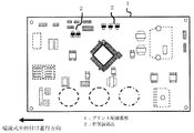
図1は、本発明の実施の形態1に係るプリント配線基板1を裏から見た概略配置を示す平面図である。ここでは、面実装部品2を含む各実装部品を配置済みの構成を示す。
プリント配線基板1には、表面に自動実装着される部品と、手挿入部品とが配設されている。
自動実装着される部品には、例えば、チップ部品抵抗、チップ部品コンデンサ、チップ部品ダイオード、ディスクリート抵抗、ディスクリートコンデンサ、ディスクリートダイオード等(いずれも図示されていない)がある。
手挿入部品には、例えば、大容量抵抗、ハイブリッドIC、トランス、コイル、大容量半導体、大型コンデンサ等(いずれも図示されていない)がある。
FIG. 1 is a plan view showing a schematic arrangement of a printed
The printed
Examples of components that are automatically mounted and mounted include chip component resistors, chip component capacitors, chip component diodes, discrete resistors, discrete capacitors, and discrete diodes (all not shown).
Examples of the manually inserted component include a large-capacity resistor, a hybrid IC, a transformer, a coil, a large-capacity semiconductor, and a large capacitor (all not shown).
プリント配線基板1の裏面には、銅箔(図示されていない)を配設している。
また、プリント配線基板1の裏面を可能な限り平面状態に保つように、面実装部品2を噴流式半田付装置の流し方向(図1中の矢印「噴流式半田付け進行方向」で示す方向)に対して垂直に自動実装する。
Copper foil (not shown) is disposed on the back surface of the printed
Further, in order to keep the back surface of the printed
図2は、本実施の形態1に係るプリント配線基板1のうち、面実装部品2の周辺を拡大表示したものである。
プリント配線基板1には、半田付けランド4、引出しパターン5が設けられている。
半田付けランド4は、面実装部品2のリード3をプリント配線基板1と接続するためのものである。
引出しパターン5は、半田付けランド4から電気的接続をするために引き出されるようにして形成されている。
FIG. 2 is an enlarged view of the periphery of the surface-mounted
The printed
The
The
引出しパターン5は、引出しパターンレジスト除去部5aと、引出しパターンレジスト塗布部5bと、から構成される。
引出しパターンレジスト除去部5aは、半田が付くようにソルダーレジストが剥がされている。
引出しパターンレジスト塗布部5bは、引出しパターンレジスト除去部5aと電気的に接続され、半田が付かないようにレジストが塗布されている。
The
In the lead pattern
The drawing pattern
本実施の形態1に係るプリント配線基板1は、従来技術のプリント配線基板における面実装部品取付ランドと比較すると、ランドから引き出される引出しパターン5の一部分のレジストが除去されている点が相違する。
The printed
なお、引出しパターンレジスト除去部5aの長さ(図2中の「A」)は、半田付けランド4の縦方向長さの略1〜2倍とするように構成することが好ましい。
The length (“A” in FIG. 2) of the lead pattern
図3は、噴流式半田付け装置を用いて、面実装部品2を本実施の形態1に係るプリント配線基板1に半田付けする作業工程を示すフローチャートである。以下、各工程について説明する。
FIG. 3 is a flowchart showing an operation process of soldering the surface-mounted
(S301)
プリント配線基板1の表面及び裏面に、自動実装機を用いて、前述の自動実装部品が実装着される。
(S302)
プリント配線基板1の表面に、前述の手挿入部品が手挿入実装着される。
(S301)
The aforementioned automatic mounting components are mounted on the front and back surfaces of the printed
(S302)
On the surface of the printed
(S303)
プリント配線基板1の裏面に、半田が銅箔になじむようにするフラックス活性剤を塗布する。
(S304)
ステップS303で塗布したフラックスが最良の活性温度となるように、半田付けを行う前の加熱を行う。
(S303)
A flux activator is applied to the back surface of the printed
(S304)
Heating before soldering is performed so that the flux applied in step S303 has the best activation temperature.
(S305)
噴流式半田付け装置が備える一次半田噴流手段は、面実装部品2を実装着したプリント配線基板1の裏面から、多数のノズルより半田を噴水のように噴出させて、半田を満遍なく面実装部品2のリード3に半田付けする。ここで用いる半田の種別は問わないが、本発明の目的に鑑み、鉛フリー半田を用いるとよい。
なお、噴流式半田付け装置の構成と半田付け工程の例は、上記特許文献2に記載されていることを付言しておく。
(S306)
ステップS305の一次半田噴流手段による半田付けが終わると、噴流式半田付け装置が備える二次半田噴流手段は、一次半田噴流手段で部品のリード間にブリッジした半田を除去する。
(S307)
面実装部品2を半田付けしたプリント配線基板1を冷却し、半田を固定する。
(S305)
The primary solder jet means included in the jet type soldering apparatus is a method in which solder is ejected from a large number of nozzles like a fountain from the back surface of the printed
Note that the configuration of the jet-type soldering apparatus and an example of the soldering process are described in the above-mentioned
(S306)
When the soldering by the primary solder jetting means in step S305 is finished, the secondary solder jetting means provided in the jet type soldering apparatus removes the solder bridged between the lead parts by the primary solder jetting means.
(S307)
The printed
以上、面実装部品2をプリント配線基板1に半田付けする作業工程を説明した。
次に、図2で説明した引き出しパターン5が、半田付け作業工程において発揮する効果について説明する。
The operation process for soldering the
Next, the effect that the
噴流式半田付け装置を用いた半田付け工程において、面実装部品2が噴流半田槽の半田噴流部へ進入すると、半田は半田付けランド4を伝って後方へ流れる。
この時、半田はリード3の上も伝わって流れるが、リード3は半田とのなじみが悪く、特に表面張力の大きい鉛フリー半田では、リード3の箇所では、半田が濡れずに弾く力が働くため、半田付け性が悪い。
In the soldering process using the jet type soldering apparatus, when the
At this time, the solder flows along the
そこで、図2で説明した引出しパターンレジスト除去部5aを設けることにより、半田付けランド4に半田を引き込みやすくする。その結果、半田付けランド4の未半田が大幅に減少する。
なお、引出しパターン5のレジストを除去せず、従来通りレジスト塗布状態にすると、本実施の形態1よりも半田付けランド4の未半田が非常に多いことが、本発明者による実証によって確認されている。
Therefore, the drawing pattern resist removing
In addition, when the resist pattern is not removed and the resist is applied as usual, the soldering
以上のように、本実施の形態1では、引出しパターン5の一部分に、レジストを塗布しない引出しパターンレジスト除去部5aを設けた。
これにより、引出しパターンレジスト除去部5aと半田がなじみやすいため、半田を半田付けランド4に引き込みやすくなる効果があり、したがって、半田濡れ性の悪い鉛フリー半田などを用いる場合でも、未半田を確実に低減することができる。
As described above, in the first embodiment, the extraction pattern resist removing
As a result, since the solder is easily compatible with the lead pattern resist removing
実施の形態2.
図4は、本発明の実施の形態2に係るプリント配線基板1のうち、面実装部品2の周辺を拡大表示したものである。
図4において、面実装部品2を半田付けする半田付けランド4の前方に、新たに格子状ランド6を設けた。その他の構成は、実施の形態1の図2で説明したものと同様であるため、説明を省略する。
なお、ここでいう前方とは、面実装部品2の噴流式半田付装置の流し方向に対して前方という意味である。
FIG. 4 is an enlarged view of the periphery of the surface-mounted
In FIG. 4, a grid-
In addition, the front here means the front with respect to the flow direction of the jet-type soldering apparatus of the
本実施の形態2における「半田表面張力低減ランド」は、格子状ランド6がこれに相当する。
The “solder surface tension reducing land” in the second embodiment corresponds to the
本実施の形態2に係るプリント配線基板1は、従来技術のプリント配線基板における面実装部品取付ランドと比較すると、実施の形態1で説明した相違点に加え、噴流式半田付装置の流し方向に対して前方に、新たに格子状ランド6を設けた点が相違する。
The printed
格子状ランド6の縦方向長さは、面実装部品2の縦方向長さの略1〜2倍とし、横方向長さは、面実装部品2の横方向長さの略1〜2倍とすることが好ましい。
The longitudinal length of the
以上、本実施の形態2に係るプリント配線基板1の構成を説明した。
次に、図4で説明した格子状ランド6が、半田付け作業工程において発揮する効果について説明する。なお、半田付け作業工程の内容は、実施の形態1の図3で説明したものと同様であるため、説明を省略する。
The configuration of the printed
Next, the effect that the grid-
噴流式半田付け装置を用いた半田付け工程において、面実装部品2が噴流半田槽の半田噴流部へ進入すると、半田は格子状ランド6、半田付けランド4を伝って後方へ流れる。
このとき、格子状ランド6は、面実装部品2の手前で格子状の1つ1つのパターンに半田が吸い取られることにより、半田の表面張力を低減させ、半田付けランド4周辺の半田を引き込む効果があり、さらに一度引き込んだ半田の表面張力を分散させる効果も同時に発揮する。半田の表面張力が分散して減少すると、半田の濡れ性が上がり、半田付け性が向上するので、半田付けランド4の未半田が大幅に減少する。
In the soldering process using the jet-type soldering apparatus, when the
At this time, the grid-
格子状ランド6を設けていない従来のプリント配線基板と比較すると、格子状ランド6を設けることにより、本実施の形態2よりも半田付けランド4の未半田が非常に多いことが、本発明者による実証によって確認されている。
Compared with the conventional printed wiring board not provided with the grid-
以上、格子状ランド6が発揮する効果について説明した。
なお、本実施の形態2の図4において、実施の形態1の図2で説明した、引出しパターンレジスト除去部5aを有する構成に加えて、新たに格子状ランド6を設けた構成を説明したが、従来と同様にレジスト除去部5aを設けていない引出しパターン5の構成の下で格子状ランド6を設ける場合でも、格子状ランド6は本実施の形態2と同様の効果を発揮することを付言しておく。
In the above, the effect which the grid-
In addition, in FIG. 4 of this
また、本実施の形態2において、新たに格子状のランド6を設けたが、その形状は必ずしも格子状である必要はなく、半田を引き込んで表面張力を分散させることのできる形状であれば、同様の効果を発揮することができる。
In the second embodiment, the grid-
以上のように、本実施の形態2では、噴流式半田付装置の流し方向に対して面実装部品2の前方に格子状ランド6を設け、半田の表面張力を低減することにより、半田付けランド4の未半田を大幅に減少させることが可能となり、後工程での未半田の手修正作業工程を省く効果がある。
As described above, in the second embodiment, the grid-
実施の形態3.
実施の形態2の図4で説明した格子状ランド6は、面実装部品2を実装する位置毎の前方に設けてもよいが、一部の面実装部品2の前方にのみ格子状ランド6を設けても、一定の表面張力分散効果を発揮することができる。
例えば、噴流式半田付けの進行方向の最前方に位置する面実装部品2の前方のみに設けてもよい。
The grid-
For example, you may provide only in front of the
一部の面実装部品2の前方にのみ格子状ランド6を設ける場合は、全ての面実装部品2の前方に格子状ランド6を設ける場合と比較すると、格子状ランド6を形成する工程が少なくて済み、スペースを有効に使え、かつ一定の表面張力分散効果を発揮することができる点で、有利である。
いずれの面実装部品2の前方に格子状ランド6を設けるかは、プリント配線基板1の配線構成や半田の材質などに応じて実証などを行い、適宜最適に定めればよい。
When the grid-
Which surface-mounted
実施の形態4.
図5は、本発明の実施の形態4に係る空気調和機が備える室外機12の正面図である。
図5において、室外機12は、送風機室13と圧縮機室14を備える。
送風機室13は、空気調和機の送風機13aを備える。
圧縮機室14は、圧縮機14a、扁平形状の電気品室15を備える。
FIG. 5 is a front view of the
In FIG. 5, the
The
The
電気品室15は、プリント配線基板1を内蔵している。プリント配線基板1は、実施の形態1〜2いずれかで説明したものであり、電気部品15aが実装された表面を下側に配置し、銅箔を有する裏面を平面状態として上側に配置している。
The
本実施の形態4に係る空気調和機は、実施の形態1〜2いずれかで説明したプリント配線基板1に電気部品15aを装着したので、未半田による電気部品15aなどの動作不良の発生を確実に低減することができる。
In the air conditioner according to the fourth embodiment, since the
図2や図4で説明した引出しパターンレジスト除去部5aの長さAは、1例として、2.0mmとすることができる。
また、図4で説明した格子状ランド6のサイズは、1例として縦長さ12.5mm、横長さ6.5mmで構成することができる。
格子を構成するパターン幅は、1例として以下のように構成することができる。
(1)格子状パターンのパターン幅D=0.5mm
(2)格子状パターンの縦方向間隔B=1mm
(3)格子状パターンの横方向間隔C=1mm
The length A of the drawing pattern resist removing
In addition, the size of the grid-
The pattern width constituting the lattice can be configured as follows as an example.
(1) Pattern width D of the lattice pattern D = 0.5 mm
(2) Lattice pattern vertical interval B = 1 mm
(3) Horizontal interval C = 1 mm of the lattice pattern
1 プリント配線基板、2 面実装部品、3 リード、4 半田付けランド、5 引出しパターン、5a 引出しパターンレジスト除去部、5b 引出しパターンレジスト塗布部、6 格子状ランド、12 室外機、13 送風機室、13a 送風機、14 圧縮機室、14a 圧縮機、15 電気品室、15a 電気部品。
DESCRIPTION OF
Claims (11)
前記面実装部品を装着する半田付けランドと、
前記半田付けランドから引き出して形成した引出しパターンと、
を備え、
前記引出しパターンの一部分のみ半田が付くように形成した
ことを特徴とするプリント配線基板。 A printed wiring board for mounting surface mount components,
A soldering land for mounting the surface mounting component;
A drawing pattern formed by drawing from the soldering land;
With
A printed wiring board, wherein solder is attached to only a part of the drawing pattern.
残りの部分はレジスト除去して半田が付くようにした
ことを特徴とする請求項1に記載のプリント配線基板。 Apply a resist so that a part of the drawing pattern does not have solder,
The printed wiring board according to claim 1, wherein the remaining portion is resist-removed and soldered.
前記半田付けランドの長さの略1〜2倍の長さに形成した
ことを特徴とする請求項1または請求項2に記載のプリント配線基板。 Of the drawing pattern, the part to be formed so that the solder is attached,
The printed wiring board according to claim 1, wherein the printed wiring board is formed to have a length approximately 1 to 2 times the length of the soldering land.
前記面実装部品を装着する半田付けランドを備えるとともに、
前記半田付けランドから見て、当該プリント配線基板を噴流式半田付けするとした際の半田付け進行方向前方に、半田の表面張力を低減させる半田表面張力低減ランドを設けた
ことを特徴とするプリント配線基板。 A printed wiring board for mounting surface mount components,
With a soldering land for mounting the surface mount component,
A printed wiring comprising a solder surface tension reducing land that reduces the surface tension of the solder in front of the soldering traveling direction when the printed wiring board is soldered by jet soldering as viewed from the soldering land. substrate.
前記半田表面張力低減ランドを
複数の前記半田付けランドのうち、当該プリント配線基板を噴流式半田付けするとした際の半田付け進行方向最前方にある半田付けランドの前方にのみ設けた
ことを特徴とする請求項4に記載のプリント配線基板。 A plurality of the soldering lands are provided,
The solder surface tension reducing land is provided only in front of the soldering land that is the forefront of the soldering progress direction when the printed wiring board is jet-soldered among the plurality of soldering lands. The printed wiring board according to claim 4.
ことを特徴とする請求項4または請求項5に記載のプリント配線基板。 The vertical size of the solder surface tension reducing land is approximately 1 to 2 times the vertical size of the surface mount component, and the horizontal size is approximately 1 to 2 times the horizontal size of the surface mount component. The printed wiring board according to claim 4 or 5.
ことを特徴とする請求項1ないし請求項6のいずれかに記載のプリント配線基板。 The printed circuit board according to any one of claims 1 to 6, wherein the surface mount component is soldered with lead-free solder.
ことを特徴とする空気調和機。 An air conditioner, wherein an electrical component box containing the printed wiring board according to any one of claims 1 to 7 is disposed above a compressor chamber.
当該プリント配線基板に、
前記面実装部品を装着する半田付けランドと、
前記半田付けランドから引き出して形成した引出しパターンと、
を設けておくとともに、
前記引出しパターンの一部分のみ半田が付くように形成しておき、
前記噴流式半田付け装置を用いて、前記面実装部品のリード部分を前記半田付けランドに半田付けする
ことを特徴とするプリント配線基板の半田付け方法。 A method of soldering surface mount components to a printed wiring board using a jet-type soldering device,
In the printed wiring board,
A soldering land for mounting the surface mounting component;
A drawing pattern formed by drawing from the soldering land;
As well as
Formed so that only a part of the drawer pattern is soldered,
A printed wiring board soldering method comprising: soldering a lead portion of the surface-mounted component to the soldering land using the jet soldering apparatus.
当該プリント配線基板に、
前記面実装部品を装着する半田付けランドを設けておくとともに、
前記半田付けランドから見て、前記噴流式半田付け装置の半田付け進行方向前方に、半田の表面張力を低減させる半田表面張力低減ランドを設けておき、
前記噴流式半田付け装置を用いて、前記面実装部品のリード部分を前記半田付けランドに半田付けする
ことを特徴とするプリント配線基板の半田付け方法。 A method of soldering surface mount components to a printed wiring board using a jet-type soldering device,
In the printed wiring board,
While providing a soldering land for mounting the surface mounting component,
As seen from the soldering land, a solder surface tension reducing land for reducing the surface tension of the solder is provided in front of the soldering traveling direction of the jet soldering device,
A printed wiring board soldering method comprising: soldering a lead portion of the surface-mounted component to the soldering land using the jet soldering apparatus.
ことを特徴とする請求項9または請求項10に記載のプリント配線基板の半田付け方法。 The method for soldering a printed wiring board according to claim 9 or 10, wherein the surface-mounted component is soldered with lead-free solder.
Priority Applications (4)
| Application Number | Priority Date | Filing Date | Title |
|---|---|---|---|
| JP2007315713A JP2009141106A (en) | 2007-12-06 | 2007-12-06 | Printed circuit board, air conditioner, and soldering method for printed circuit board |
| US12/219,530 US20090145644A1 (en) | 2007-12-06 | 2008-07-23 | Printed wiring board, air conditioner, and method of soldering printed wiring board |
| CN2008101334790A CN101453836B (en) | 2007-12-06 | 2008-07-25 | Printed wiring board, air conditioner, and method of soldering printed wiring board |
| CN2010105207306A CN101969742A (en) | 2007-12-06 | 2008-07-25 | Printed wiring board, air conditioner, and method of soldering printed wiring board |
Applications Claiming Priority (1)
| Application Number | Priority Date | Filing Date | Title |
|---|---|---|---|
| JP2007315713A JP2009141106A (en) | 2007-12-06 | 2007-12-06 | Printed circuit board, air conditioner, and soldering method for printed circuit board |
Related Child Applications (1)
| Application Number | Title | Priority Date | Filing Date |
|---|---|---|---|
| JP2009199661A Division JP2009283983A (en) | 2009-08-31 | 2009-08-31 | Printed wiring board, air conditioner, and soldering method for printed wiring board |
Publications (2)
| Publication Number | Publication Date |
|---|---|
| JP2009141106A true JP2009141106A (en) | 2009-06-25 |
| JP2009141106A5 JP2009141106A5 (en) | 2009-08-06 |
Family
ID=40720450
Family Applications (1)
| Application Number | Title | Priority Date | Filing Date |
|---|---|---|---|
| JP2007315713A Pending JP2009141106A (en) | 2007-12-06 | 2007-12-06 | Printed circuit board, air conditioner, and soldering method for printed circuit board |
Country Status (3)
| Country | Link |
|---|---|
| US (1) | US20090145644A1 (en) |
| JP (1) | JP2009141106A (en) |
| CN (2) | CN101453836B (en) |
Families Citing this family (2)
| Publication number | Priority date | Publication date | Assignee | Title |
|---|---|---|---|---|
| JP6921244B2 (en) * | 2018-01-15 | 2021-08-18 | 本田技研工業株式会社 | Blaze device and method |
| WO2019211998A1 (en) * | 2018-05-01 | 2019-11-07 | 三菱電機株式会社 | Soldering nozzle, soldering device, soldering method, and method for manufacturing printed wiring board |
Family Cites Families (8)
| Publication number | Priority date | Publication date | Assignee | Title |
|---|---|---|---|---|
| US5666272A (en) * | 1994-11-29 | 1997-09-09 | Sgs-Thomson Microelectronics, Inc. | Detachable module/ball grid array package |
| US5679929A (en) * | 1995-07-28 | 1997-10-21 | Solectron Corporqtion | Anti-bridging pads for printed circuit boards and interconnecting substrates |
| US5877033A (en) * | 1997-03-10 | 1999-03-02 | The Foxboro Company | System for detection of unsoldered components |
| JP3633505B2 (en) * | 2001-04-27 | 2005-03-30 | 松下電器産業株式会社 | Printed circuit board and printed circuit board soldering method |
| CN100446650C (en) * | 2001-12-18 | 2008-12-24 | 爱立信股份有限公司 | Apparatus and method for assembling electronic circuits |
| JP2006313792A (en) * | 2005-05-06 | 2006-11-16 | Sony Corp | Printed wiring board |
| JP4207934B2 (en) * | 2005-08-09 | 2009-01-14 | 三菱電機株式会社 | 4 direction lead flat package IC mounting printed wiring board, 4 direction lead flat package IC soldering method, air conditioner. |
| CN1852638B (en) * | 2006-01-24 | 2010-05-12 | 华为技术有限公司 | Printing welding-paste method and printing tin steel-screen |
-
2007
- 2007-12-06 JP JP2007315713A patent/JP2009141106A/en active Pending
-
2008
- 2008-07-23 US US12/219,530 patent/US20090145644A1/en not_active Abandoned
- 2008-07-25 CN CN2008101334790A patent/CN101453836B/en not_active Expired - Fee Related
- 2008-07-25 CN CN2010105207306A patent/CN101969742A/en active Pending
Also Published As
| Publication number | Publication date |
|---|---|
| US20090145644A1 (en) | 2009-06-11 |
| CN101453836A (en) | 2009-06-10 |
| CN101969742A (en) | 2011-02-09 |
| CN101453836B (en) | 2011-03-30 |
Similar Documents
| Publication | Publication Date | Title |
|---|---|---|
| JP4207934B2 (en) | 4 direction lead flat package IC mounting printed wiring board, 4 direction lead flat package IC soldering method, air conditioner. | |
| US8923007B2 (en) | Multi-diameter unplugged component hole(s) on a printed circuit board (PCB) | |
| US10843284B2 (en) | Method for void reduction in solder joints | |
| JP5496118B2 (en) | Soldering method and air conditioner for printed wiring board, 4-way lead flat package IC | |
| JP2009141106A (en) | Printed circuit board, air conditioner, and soldering method for printed circuit board | |
| JP3988720B2 (en) | 4 direction lead flat package IC mounting printed wiring board and soldering method of 4 direction lead flat package IC mounting, air conditioner provided with 4 direction lead flat package IC mounting printed wiring board. | |
| JP2009283983A (en) | Printed wiring board, air conditioner, and soldering method for printed wiring board | |
| JP5599151B2 (en) | Double-row lead-type electronic component mounting printed circuit board, double-row lead-type electronic component soldering method, air conditioner | |
| JP4196979B2 (en) | Lead-type electronic component mounting printed wiring board, lead-type electronic component soldering method, air conditioner. | |
| EP1603375B1 (en) | Printed circuit board, method of soldering electronic components, and air conditioning apparatus with printed circuit board | |
| JP2009141106A5 (en) | ||
| JP2008091557A (en) | Electronic component mounting method and apparatus | |
| JP2006313792A (en) | Printed wiring board | |
| JP2008112778A (en) | Printed-wiring board, and motor control unit having the same | |
| JP5885162B2 (en) | Printed wiring board | |
| JP2006286899A (en) | Manufacturing method of printed wiring board | |
| JP2007250732A (en) | Electronic component and its manufacturing method | |
| KR101211167B1 (en) | Printed circuit board having the residual flux discharging portion and surface mounting package | |
| JP4543205B2 (en) | Partial soldering method for printed circuit boards | |
| JP2018107381A (en) | Printed circuit assembly and manufacturing method thereof | |
| JPH09181424A (en) | Electronic component, printed wiring board and manufacturing method thereof | |
| JP2011114050A (en) | Structure for mounting electronic component | |
| TH103225B (en) | Electrical panel, air conditioner and electrical panel soldering methods Type | |
| JP2013110333A (en) | Soldering method of substrate and component with lead | |
| JP2006114720A (en) | Mounting board and its manufacturing method |
Legal Events
| Date | Code | Title | Description |
|---|---|---|---|
| A521 | Request for written amendment filed |
Free format text: JAPANESE INTERMEDIATE CODE: A523 Effective date: 20090610 |
|
| A621 | Written request for application examination |
Free format text: JAPANESE INTERMEDIATE CODE: A621 Effective date: 20090610 |
|
| A131 | Notification of reasons for refusal |
Free format text: JAPANESE INTERMEDIATE CODE: A131 Effective date: 20090721 |
|
| A02 | Decision of refusal |
Free format text: JAPANESE INTERMEDIATE CODE: A02 Effective date: 20091124 |