JP2009141048A - Optical system and atomic oscillator - Google Patents
Optical system and atomic oscillator Download PDFInfo
- Publication number
- JP2009141048A JP2009141048A JP2007314481A JP2007314481A JP2009141048A JP 2009141048 A JP2009141048 A JP 2009141048A JP 2007314481 A JP2007314481 A JP 2007314481A JP 2007314481 A JP2007314481 A JP 2007314481A JP 2009141048 A JP2009141048 A JP 2009141048A
- Authority
- JP
- Japan
- Prior art keywords
- light
- optical system
- light source
- atomic oscillator
- gas cell
- Prior art date
- Legal status (The legal status is an assumption and is not a legal conclusion. Google has not performed a legal analysis and makes no representation as to the accuracy of the status listed.)
- Withdrawn
Links
Images


Classifications
-
- G—PHYSICS
- G04—HOROLOGY
- G04F—TIME-INTERVAL MEASURING
- G04F5/00—Apparatus for producing preselected time intervals for use as timing standards
- G04F5/14—Apparatus for producing preselected time intervals for use as timing standards using atomic clocks
Abstract
Description
本発明は、原子発振器の光学系に関し、さらに詳しくは、原子発振器を構成する光学系に含まれる光源のパワー制御技術に関するものである。 The present invention relates to an optical system of an atomic oscillator, and more particularly to a power control technique for a light source included in an optical system constituting the atomic oscillator.
ルビジウム、セシウム等のアルカリ金属を用いた原子発振器は、原子のエネルギ遷移を利用する際に、原子をガス状態に保つ必要があるため、原子を気密封入したガスセルを高温に保って動作させている。原子発振器の動作原理は、光とマイクロ波を利用した二重共鳴法と、2種類のレーザ光による量子干渉効果(以下CPT:Coherent Population Trappingと記す)を利用する方法に大別されるが、両者共にガスセルに入射した光が、原子ガスにどれだけ吸収されたかを反対側に設けられた検出器で検出することにより、原子共鳴を検知して制御系にて水晶発振器などの基準信号をこの原子共鳴に同期させて出力を得ている。ここで、CPTを利用した原子発振器は、発光素子、ガスセル、及び受光素子を一体的に構成して光学系を形成している(特許文献1参照)。
しかし、特許文献1に開示されている従来の光学系の構成では、図6に示すように発光素子93、ガスセル95、及び受光素子90が縦積みに配置されている。このため、最上面に配置した受光素子90を電気的に接続するボンディングワイヤ91が長くなり、モジュールの実装構造が複雑となるばかりでなく、受光素子90から得られる信号が微弱なためにワイヤに重畳するノイズの影響を受けやすくなりS/N特性が低下するといった問題もある。また、発光素子93のパワーや波長が変動した場合に、その変動を制御する方法として図7のように、従来の構成では温度制御部105からのCoarse信号100、EIT信号からのFine信号101によりVCSEL106の安定化制御を行なっていた。このためEIT信号からのFine信号101は原子ガスセルの擾乱に対して影響を受けるため、正確なVCSELの強度情報を検出することができなかった。また、Coarse信号100は温度制御部105からの独立制御であるため、温度変化に対して追従しないといった問題があった。
However, in the configuration of the conventional optical system disclosed in Patent Document 1, the
本発明は、かかる課題に鑑み、発光素子から出射した光を光分岐素子により分岐して、一方の光をガスセル側に入射させて第1の受光素子により受光し、他方の光を第2の受光素子により受光することにより、発光素子から出射した光の変動をリアルタイムに検出して発光素子のパワーと波長を制御することができる原子発振器の光学系を提供することを目的とする。
また、他の目的は、受光素子を発光素子と同一側に併置することにより、受光素子を電気的に接続するボンディングワイヤを短くしてモジュール実装を容易とし、且つ、S/Nを改善することである。
In view of such a problem, the present invention branches light emitted from a light emitting element by a light branching element, makes one light incident on the gas cell side, receives it by the first light receiving element, and receives the other light by the second light. An object of the present invention is to provide an optical system of an atomic oscillator that can detect the fluctuation of light emitted from a light emitting element in real time and control the power and wavelength of the light emitting element by receiving light from the light receiving element.
Another object is to arrange the light receiving element on the same side as the light emitting element, thereby shortening the bonding wire for electrically connecting the light receiving element, facilitating module mounting, and improving S / N. It is.
本発明はかかる課題を解決するために、波長が異なるコヒーレント光としての2種類の共鳴光を入射したときの量子干渉効果による光吸収特性を利用して発振周波数を制御する原子発振器の光学系であって、前記共鳴光を出射するコヒーレント光源と、前記コヒーレント光源の出射側に配置され前記共鳴光を少なくとも2つの光路に分岐する光分岐手段と、前記光分岐手段により分岐された一方の共鳴光の出射側に配置されガス状の金属原子を封入すると共に、該金属原子ガス中に該共鳴光を通過させるガスセルと、前記ガスセルを通過した光を再び該ガスセルに導く導光手段と、前記ガスセルを通過した光を検出する第1の光検出手段と、前記光分岐手段により分岐された他方の共鳴光を検出する第2の光検出手段と、前記第2の光検出手段により検出された共鳴光の強度に基づいて前記コヒーレント光源の強度を制御する光源制御部と、を備えたことを特徴とする。 In order to solve such a problem, the present invention is an optical system of an atomic oscillator that controls an oscillation frequency by utilizing a light absorption characteristic due to a quantum interference effect when two types of resonant light as coherent lights having different wavelengths are incident. A coherent light source that emits the resonant light, an optical branching unit that is arranged on the outgoing side of the coherent light source and branches the resonant light into at least two optical paths, and one of the resonant lights branched by the optical branching unit A gas cell that is disposed on the emission side of the gas, encloses gaseous metal atoms, allows the resonance light to pass through the metal atom gas, light guide means that guides the light that has passed through the gas cell to the gas cell, and the gas cell. A first light detecting means for detecting light that has passed through the second light detecting means, a second light detecting means for detecting the other resonance light branched by the light branching means, and the second light detecting means. Characterized by comprising a light source control section for controlling the intensity of the coherent light source based on the intensity of the detected resonant light by.
本発明の原子発振器は、レーザ光などのコヒーレント光の量子干渉効果を利用したものである。この方式は、2つの基底準位が共鳴光を受けて、共通の励起準位と共鳴結合している3準位系(例えばΛ型準位系)において、同時に照射される2つの共鳴光の周波数が正確に基底準位1と基底準位2のエネルギ差に一致すると、3準位系は2つの基底準位の重ね合わせの状態になり、励起準位3への励起が停止する。CPTはこの原理を利用して、2つの共鳴光の一方或いは両方の波長を変化させたときに、ガスセルでの光吸収が停止する状態を検出して利用するものである。そして、本発明の光学系は、コヒーレント光源と第1及び第2の光検出手段を同一側に実装し、コヒーレント光源からの共鳴光を分岐して、一方の共鳴光はガスセルに入射させて第1の光検出手段により検出し、他方の共鳴光はガスセルを通過させずに第2の光検出手段により検出する。これにより、コヒーレント光源の光の強度変動をガスセル等の他の影響を受けずに監視することができる。
The atomic oscillator of the present invention utilizes the quantum interference effect of coherent light such as laser light. In this method, two ground levels of two resonant lights irradiated simultaneously in a three-level system (for example, a Λ-type level system) in which two ground levels receive resonant light and are resonantly coupled with a common excitation level. When the frequency exactly matches the energy difference between the ground level 1 and the
また、前記光分岐手段と前記第2の光検出手段との間に原子の共鳴遷移と等しい波長を通過させる光フィルタを備えたことを特徴とする。
コヒーレント光源からの共鳴光は、光の強度(パワー)の他に波長も重要なファクターとなる。波長を検出する手段としては、決められた波長だけを通過させる光フィルタを使用すればよい。そこで本発明では、光分岐手段と前記第2の光検出手段との間に原子の共鳴遷移と等しい波長を通過させる光フィルタを備える。これにより、共鳴光の波長が変動したことを検出することができる。
また、前記光源制御部は、前記光フィルタを通過した共鳴光の強度が低下した場合、前記コヒーレント光源の波長が変動したと見做して、該コヒーレント光源の波長を変更するように制御することを特徴とする。
光フィルタを通過した光は、特定の波長の光である。従って、光検出手段の検出レベルが低下したときは、コヒーレント光源からの共鳴光の波長が変動して光フィルタにより阻止されたと見做すことができる。そこで本発明では、そのような時は、コヒーレント光源の波長を変更するように制御する。これにより、コヒーレント光源の波長変動を即座に検出して補正することができる。
In addition, an optical filter is provided between the optical branching unit and the second optical detection unit to pass a wavelength equal to an atomic resonance transition.
In addition to the intensity (power) of light, the wavelength of resonance light from a coherent light source is an important factor. As a means for detecting the wavelength, an optical filter that passes only a predetermined wavelength may be used. Therefore, in the present invention, an optical filter that allows passage of a wavelength equal to the resonance transition of atoms is provided between the light branching means and the second light detection means. Thereby, it can be detected that the wavelength of the resonance light has fluctuated.
Further, the light source control unit assumes that the wavelength of the coherent light source has changed when the intensity of the resonant light that has passed through the optical filter is decreased, and performs control to change the wavelength of the coherent light source. It is characterized by.
The light that has passed through the optical filter is light of a specific wavelength. Therefore, when the detection level of the light detection means decreases, it can be considered that the wavelength of the resonance light from the coherent light source fluctuates and is blocked by the optical filter. Therefore, in the present invention, in such a case, control is performed so as to change the wavelength of the coherent light source. Thereby, the wavelength fluctuation of the coherent light source can be immediately detected and corrected.
また、前記光分岐手段は、ビームスプリッタ又はハーフミラーにより構成されていることを特徴とする。
コヒーレント光源から出射された共鳴光の変動を検出するためには、可能な限りコヒーレント光源の生の光を検出することが好ましい。そこで本発明では、コヒーレント光源から出射された光の一部を分岐して検出する。それにはビームスプリッタ又はハーフミラーが好都合である。これらの素子は、入射した一部の光を通過して、他の一部の光の光路を変換する特性がある。これにより、共鳴光を少なくとも2つの光路に分岐することができる。
また、前記コヒーレント光源の周囲温度を制御する温度制御素子を備えたことを特徴とする。
コヒーレント光源は、周囲温度により光源の強度(パワー)及び波長(周波数)が変動する特性を有している。そこで本発明では、パワー及び波長を調整するために、積極的にコヒーレント光源の周囲温度を制御する例えばペルチェ素子のような温度制御素子を設ける。これにより、外部からパワー及び波長を所定量変更することができる。
Further, the light branching means is constituted by a beam splitter or a half mirror.
In order to detect fluctuations in the resonant light emitted from the coherent light source, it is preferable to detect the raw light from the coherent light source as much as possible. Therefore, in the present invention, a part of the light emitted from the coherent light source is branched and detected. A beam splitter or half mirror is convenient for this. These elements have a characteristic of passing an incident part of light and converting the optical path of the other part of light. Thereby, the resonance light can be branched into at least two optical paths.
Further, a temperature control element for controlling an ambient temperature of the coherent light source is provided.
The coherent light source has a characteristic that the intensity (power) and wavelength (frequency) of the light source vary depending on the ambient temperature. Therefore, in the present invention, in order to adjust the power and wavelength, a temperature control element such as a Peltier element that actively controls the ambient temperature of the coherent light source is provided. Thereby, a predetermined amount of power and wavelength can be changed from the outside.
前記第1及び第2の光検出手段と、前記コヒーレント光源とをガスセルに対して同一側に併置したことを特徴とする。
本発明の光学系は、コヒーレント光源と第1及び第2の光検出手段とをガスセルに対して同一側に実装し、透過光が第1の光検出手段により受光され、コヒーレント光源から出射した光の一部が第2の光検出手段により受光されるように導光手段を構成した。これにより、ボンディングワイヤが短くなり、信号のS/N特性を改善すると共に、光学系全体の実装も容易にすることができる。
前記導光手段は、反射部材により構成されていることを特徴とする。
導光手段に入射した透過光を第1の光検出手段に折り返すにはミラー等の反射部材が最適である。これにより、透過光を所望の光路により第2の光検出手段と併置した第1の光検出手段に入射させることができる。
前記コヒーレント光は、レーザ光であることを特徴とする。
普通の光は、いろいろな波長が混ざり位相がランダムな光である。これに対してレーザ光は波長の単色性が良く、位相の揃った光である。このような光の波長や位相の安定性の尺度としてコヒーレンスが定義されている。コヒーレンスが良い、すなわち波長や位相が安定な光は量子干渉効果を起こすことができる。その点ではレーザ光は最適である。
The first and second light detection means and the coherent light source are juxtaposed on the same side with respect to the gas cell.
In the optical system of the present invention, the coherent light source and the first and second light detection means are mounted on the same side with respect to the gas cell, and the transmitted light is received by the first light detection means and emitted from the coherent light source. The light guide means is configured so that a part of the light is received by the second light detection means. As a result, the bonding wire is shortened, the signal S / N characteristic is improved, and the entire optical system can be easily mounted.
The light guide means is constituted by a reflecting member.
A reflecting member such as a mirror is optimal for returning the transmitted light incident on the light guiding means to the first light detecting means. Thereby, the transmitted light can be made incident on the first light detection means arranged in parallel with the second light detection means by a desired optical path.
The coherent light is laser light.
Ordinary light is light in which various wavelengths are mixed and the phase is random. On the other hand, laser light has good monochromaticity in wavelength and is light with a uniform phase. Coherence is defined as a measure of the stability of the wavelength and phase of light. Light with good coherence, that is, with stable wavelength and phase, can cause a quantum interference effect. In that respect, laser light is optimal.
前記ガス状の金属原子は、ルビジウム、又はセシウムであることを特徴とする。
セシウム原子を使えば、精度の高い原子発振器を実現できる。また、ルビジウム原子は手軽に広く普及している。よって、原子発振器の要求性能とコストを考慮して、いずれかの金属原子を選ぶことができる。
前記コヒーレント光源から出射された光を集光し、且つ平行光に補正する受動光学素子を前記コヒーレント光源と前記ガスセルとの間に配置したことを特徴とする。
光学系には、コヒーレント光源から出射された光を集光して、平行光になるように補正するためにレンズや波長板といった受動光学素子が使用される。この受動光学素子は、ガスセルに入射する前であればどこに配置しても構わない。そこで本発明では、受動光学素子をコヒーレント光源とガスセルとの間に配置する。これにより、光を正確に導光手段に入射させることができる。
また、上記構成による光学系を原子発振器に備えたことを特徴とする。
ガスセルを複数回通過する構造としたことで、より大きなEIT信号を得る光学系とすることができるので、S/Nが向上した高性能な原子発振器を提供することができる。
The gaseous metal atom is rubidium or cesium.
If cesium atoms are used, a highly accurate atomic oscillator can be realized. In addition, rubidium atoms are widely spread easily. Therefore, any metal atom can be selected in consideration of the required performance and cost of the atomic oscillator.
A passive optical element that condenses the light emitted from the coherent light source and corrects the light into parallel light is disposed between the coherent light source and the gas cell.
In the optical system, a passive optical element such as a lens or a wave plate is used for condensing the light emitted from the coherent light source and correcting it to become parallel light. This passive optical element may be disposed anywhere before entering the gas cell. Therefore, in the present invention, the passive optical element is disposed between the coherent light source and the gas cell. Thereby, light can be accurately incident on the light guide means.
Further, the optical system having the above configuration is provided in an atomic oscillator.
By adopting a structure that passes through the gas cell a plurality of times, it is possible to provide an optical system that obtains a larger EIT signal, so that a high-performance atomic oscillator with improved S / N can be provided.
以下、本発明を図に示した実施形態を用いて詳細に説明する。但し、この実施形態に記載される構成要素、種類、組み合わせ、形状、その相対配置などは特定的な記載がない限り、この発明の範囲をそれのみに限定する主旨ではなく単なる説明例に過ぎない。
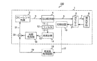
図1は本発明の実施形態に係る原子発振器の光学系の要部構成図である。この光学系1は、波長が異なるコヒーレント光としての2種類の共鳴光を入射したときの量子干渉効果による光吸収特性を利用して発振周波数を制御する原子発振器100の光学系1であって、共鳴光3を出射するコヒーレント光源2と、コヒーレント光源2の出射側に配置され共鳴光3を少なくとも2つの光路に分岐する光分岐手段4と、光分岐手段4により分岐された一方の共鳴光5の出射側に配置されガス状の金属原子を封入すると共に、金属原子ガス中に共鳴光5を通過させるガスセル6と、ガスセル6を通過した光7を再びガスセル6に導く導光手段8と、ガスセル6を通過した光9を検出する光検出器(第1の光検出手段)10と、光分岐手段4により分岐された他方の共鳴光11を検出する光検出器(第2の光検出手段)14と、光検出器14により検出された共鳴光15の強度に基づいてコヒーレント光源2の強度を制御する光源制御部16と、光分岐手段4と光検出器14との間に原子の共鳴遷移と等しい波長を通過させる光フィルタ12と、を備えている。尚、符号30は、光源制御部16と周波数制御回路18との信号を合成してコヒーレント光源に入力する合成回路である。原子発振器100は光検出器10の出力信号により、発振周波数を制御する周波数制御回路18を更に備えて構成されている。また、本発明の主旨は、原子発振器を構成する光学系の構成にあるので、原子発振器の周波数制御についての詳細な説明は省略する。
Hereinafter, the present invention will be described in detail with reference to embodiments shown in the drawings. However, the components, types, combinations, shapes, relative arrangements, and the like described in this embodiment are merely illustrative examples and not intended to limit the scope of the present invention only unless otherwise specified. .
FIG. 1 is a configuration diagram of a main part of an optical system of an atomic oscillator according to an embodiment of the present invention. This optical system 1 is an optical system 1 of an
即ち、本発明の原子発振器100は、レーザ光などのコヒーレント光の量子干渉効果を利用したものである。この方式は、2つの基底準位が共鳴光を受けて、共通の励起準位と共鳴結合している3準位系(例えばΛ型準位系)において、同時に照射される2つの共鳴光の周波数が正確に基底準位1と基底準位2のエネルギ差に一致すると、3準位系は2つの基底準位の重ね合わせの状態になり、励起準位3への励起が停止する。CPTはこの原理を利用して、2つの共鳴光の一方或いは両方の波長を変化させたときに、ガスセルでの光吸収が停止する状態を検出して利用するものである。そして、本発明の光学系1は、コヒーレント光源2と光検出手段10、14とを、ガスセルに対して同一側に実装し、コヒーレント光源2からの共鳴光3を分岐して、一方の共鳴光5はガスセル6に入射させて導光手段8を介して光検出手段10により検出し、他方の共鳴光11はガスセル6を通過させずに光検出器14により検出する。これにより、コヒーレント光源2の光の強度変動をガスセル6等の他の影響を受けずに監視することができる。
That is, the
また、コヒーレント光源2からの共鳴光3は、光の強度(パワー)の他に波長も重要なファクターとなる。波長を検出する手段としては、決められた波長だけを通過させる光フィルタ12を使用すればよい。そこで本発明では、光分岐手段4と光検出器14との間に原子の共鳴遷移と等しい波長を通過させる光フィルタ12を備える。これにより、共鳴光3の波長が変動したことを検出することができる。
また、光フィルタ12を通過した光は、特定の波長の光である。従って、光検出器14の検出レベルが低下したときは、コヒーレント光源からの共鳴光の波長が変動して光フィルタ12により阻止されたと見做すことができる。そこで本発明では、そのような時は、コヒーレント光源2の波長を変更するように制御する。これにより、コヒーレント光源2の波長変動を即座に検出して補正することができる。
In addition, the wavelength of the resonant light 3 from the coherent
The light that has passed through the
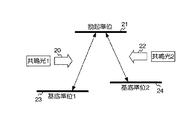
図2はCPT方式による原子の3準位系を説明する一例である。原子発振器に用いられるルビジウムやセシウムの基底準位は、核スピン−電子スピン相互作用による超微細構造により2種類の基底準位に分かれている。これらの基底準位の原子は光を吸収して、よりエネルギーの高い準位へ励起する。また、図2の様に2つの基底準位が光を受けて、共通の励起準位と共鳴結合している状態を2光子共鳴と言う。図2において、基底準位1(23)と基底準位2(24)は準位のエネルギが若干異なるため、共鳴光もそれぞれ共鳴光1(20)と共鳴光2(22)と波長が若干異なる。同時に照射される共鳴光1(20)と共鳴光2(22)の周波数差(波長の差)が正確に基底準位1(23)と基底準位2(24)のエネルギ差に一致すると、図2の系は2つの基底準位の重ね合わせ状態になり、励起準位21への励起が停止する。CPTはこの原理を利用して、共鳴光1(20)と共鳴光2(22)のどちらかまたは両方の波長を変化させたときに、ガスセル3での光吸収(つまり励起準位21への転換)が停止する状態を検出、利用する方式である。尚、この光吸収が停止する状態でガスセル6を通過する透過光をEIT信号と呼ぶ。
FIG. 2 is an example for explaining a three-level system of atoms by the CPT method. The rubidium and cesium ground levels used in the atomic oscillator are divided into two kinds of ground levels by the hyperfine structure due to the nuclear spin-electron spin interaction. These ground level atoms absorb light and excite to higher energy levels. A state in which two ground levels receive light and are resonantly coupled to a common excitation level as shown in FIG. 2 is called two-photon resonance. In FIG. 2, since the ground level 1 (23) and the ground level 2 (24) have slightly different levels of energy, the resonant light also has a wavelength slightly different from that of the resonant light 1 (20) and the resonant light 2 (22), respectively. Different. When the frequency difference (wavelength difference) between the resonant light 1 (20) and the resonant light 2 (22) irradiated at the same time exactly matches the energy difference between the ground level 1 (23) and the ground level 2 (24), The system shown in FIG. 2 enters a superposition state of two ground levels, and excitation to the
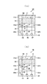
図3(a)は本発明の第1の実施形態に係る光学系の構成を模式化した図である。この光学系1Aは、基板48上に発光素子(図1のコヒーレント光源2)33と受光素子(図1の光検出器10)47と受光素子(図1の光検出器14)46を併置し、夫々の素子がボンディングワイヤ32により基板48に電気的に接続されている。そして、スペーサ49a、49bにより所定の距離を確保して、その上に発光素子33から出射されたコヒーレント光35を集光したり、平行光に変換したり、或いは偏光状態を変える受動光学素子34を備え、その上にビームスプリッタ36と、ビームスプリッタ36により分岐された共鳴光43を基板48に導く第2ミラー44が備えられている。そして、スペーサ50a、50bにより所定の距離を確保して、その上にガスセル38があり、スペーサ51a、51bにより所定の距離を確保して、第1ミラー39、41(図1の導光手段8)により透過光40を受光素子47に導光している。
FIG. 3A is a diagram schematically illustrating the configuration of the optical system according to the first embodiment of the present invention. In this
次に、図3(a)により概略動作について説明する。発光素子33から出射されたコヒーレント光35は、受動光学素子34により集光されて平行光に補正されてビームスプリッタ(光分岐手段)36に入射する。ビームスプリッタ36はコヒーレント光35を2つの光路に分岐する。一方の光43は第2ミラー44に入射して直角に反射されて受光素子46により受光される。また、他方の光37はガスセル38に入射する。ガスセル38は2つの波長を有する光37の一方或いは両方の波長を変化させたときに、光吸収が停止するように動作する。ガスセル38を通過した光は第1ミラー39により直角に反射され、同じく第1ミラー41により直角に反射されて再びガスセル38に入射する。ガスセル38を通過した光42は、受光素子47により受光される。尚、発光素子33として面発光型レーザ(VCSEL)、受光素子46、47としてフォトダイオードが良く使用される。
Next, the schematic operation will be described with reference to FIG. The
尚、光学系1Aは、発光素子33と受光素子46、47とをガスセル38に対して同一側に実装し、透過光が受光素子47により受光され、コヒーレント光源から出射した光の一部が受光素子46により受光されるように第1ミラー39、41、及び第2ミラー44を構成した。これにより、ボンディングワイヤが短くなり、信号のS/N特性を改善すると共に、光学系全体の実装も容易にすることができる。
また、発光素子33から出射された共鳴光35の変動を検出するためには、可能な限り発光素子33の出射光を直接検出することが好ましい。そこで本実施形態では、発光素子33から出射された光35の一部を分岐して検出する。それにはビームスプリッタ又はハーフミラーが好都合である。これらの素子は、入射した一部の光を通過して、他の一部の光の光路を分岐する特性がある。これにより、共鳴光を少なくとも2つの光路に分岐することができる。
また、入射した透過光を第1のミラー39、41に折り返すにはミラー等の反射部材が最適である。これにより、透過光を所望の光路により光検出器46と併置した光検出器47に入射させることができる。
また、光学系には、発光素子33から発光された光を集光して、平行光になるように補正するためにレンズや波長板といった受動光学素子34が使用される。この受動光学素子34は、ガスセル38に入射する前であればどこに配置しても構わない。そこで本実施形態では、受動光学素子34を発光素子33とガスセル38との間に配置する。これにより、光を正確に第1ミラー39に入射させることができる。
In the
Further, in order to detect the fluctuation of the
Further, a reflecting member such as a mirror is optimal for returning the incident transmitted light to the
Further, in the optical system, a passive
尚、本実施形態の発光素子33は、レーザ光を使用している。レーザ光は波長の単色性が良く、位相の揃った光である。このような光の波長や位相の安定性の尺度としてコヒーレンスが定義されている。コヒーレンスが良い、すなわち波長や位相が安定な光は量子干渉効果を起こすことができる。その点ではレーザ光は最適である。また、ガスセル38に使用するガス状の金属原子は、ルビジウム、又はセシウムである。1次原子標準器に使われるセシウム原子を使えば、精度の高い原子発振器を実現できる。また、2次標準器で使われるルビジウム原子は手軽に広く普及しているため、これを使えば一般的には小型で低価格な原子発振器を実現できる。従って、金属原子に何を用いるかは、使用目的により選択すればよい。なお、本実施形態ではルビジウム、セシウムを用いたがΛ型準位系等の3準位系を持った原子であればどのような原子であっても構わない。
Note that the
図3(b)は本発明の第2の実施形態に係る光学系の構成を模式化した図である。同じ構成要素には図3(a)と同じ参照番号を付して説明する。この光学系1Bは、ビームスプリッタ36と(第2ミラー44を介して)受光素子46との間に光フィルタ52を設けている。他の構成は図3(a)と同じであるので説明を省略する。即ち、発光素子33からの共鳴光35は、光の強度(パワー)の他に波長も重要なファクターとなる。波長を検出する手段としては、決められた波長だけを通過させる光フィルタ52を使用すればよい。そこで本実施形態では、ビームスプリッタ36と受光素子46との間に原子の共鳴遷移と等しい波長を通過させる光フィルタ52を備える。これにより、光源制御部16は、共鳴光の波長が変動したことを受光素子46のレベルの変動から検出することができる。尚、光フィルタ52はビームスプリッタ36と受光素子46の間であれば何処でも構わない。
FIG. 3B is a diagram schematically showing the configuration of the optical system according to the second embodiment of the present invention. The same constituent elements will be described with the same reference numerals as in FIG. In the optical system 1B, an
図4(a)、(b)は、図3(a)、(b)の構成による光学系を駆動する光源制御部を説明する図である。同じ構成要素には図1、図3と同じ参照番号を付し重複する説明は省略する。図4(a)は図3(a)に対応し、図4(b)は図3(b)に対応している。まず図4(a)の構成について説明する。光学系1Aの発光素子33を発光させるためのレーザドライバ62と、受光素子47の出力信号を増幅するアンプ65と、ガスセル38の温度を検知するサーミスタ61の出力信号を増幅するアンプ64と、受光素子46の出力信号を増幅するアンプ63と、を備え、各アンプ63〜65の出力信号に基づいて発光素子33の強度を制御する光源制御部(MCUにより構成)16からの出力信号66を合成回路30により変調信号19と合成されてレーザドライバ62に入力される。また、光源制御部16からは、加熱素子60を一定温度に加熱する制御信号67が出力される。尚、図4(a)、(b)では、受動光学素子34と第1ミラー39、41を省略している。従って、受光素子47に入射する光の経路ついては、ガスセル38を往復する光の経路を一部省略している。
FIGS. 4A and 4B are diagrams illustrating a light source control unit that drives the optical system having the configuration of FIGS. 3A and 3B. The same components are denoted by the same reference numerals as those in FIGS. 1 and 3, and redundant description is omitted. 4 (a) corresponds to FIG. 3 (a), and FIG. 4 (b) corresponds to FIG. 3 (b). First, the configuration of FIG. 4A will be described. A
次に図4(a)の構成による光源制御部の概略動作について説明する。発光素子33から出射されたコヒーレント光35はビームスプリッタ36に入射する。ビームスプリッタ36はコヒーレント光35を2つの光路に分岐する。一方の光43はミラー44に入射して直角に反射されて受光素子46により受光される。受光素子46の出力信号はアンプ63により増幅されて光源制御部16に入力される。また、他方の光37はガスセル38に入射する。ガスセル38は2つの波長を有する光37の一方或いは両方の波長を変化させたときに、光吸収が停止するように動作する。ガスセル38を通過した光は受光素子47により受光される。受光素子47の出力信号はアンプ65により増幅されて光源制御部16に入力される。ここで、発光素子33が何らかの原因により、発光強度に変動が生じた場合は、受光素子46により受光する光の強度が変動するため、その信号はアンプ63により増幅されて光源制御部16により検出される。光源制御部16は、その変動量に基づいて、例えば、規定の強度より弱い場合は、レーザドライバ62を介して発光素子33の電流を増加するように制御する。また、逆に規定の強度より強い場合は、レーザドライバ62を介して発光素子33の電流を減少させるように制御する。このとき、レーザドライバ62の電流を増減しても変動しない場合は、発光素子33が故障したと判断する。尚、判断基準は適宜決められる。また、光源制御部16は、サーミスタ61の信号を常時監視して、ガスセル38が一定の温度に維持されるように加熱素子60を制御する。例えば、サーミスタ61からの温度信号が高いと判断した場合は、加熱素子60に流す電流を低下或いは反転させて加熱温度を低下させ、逆にサーミスタ61からの温度信号が低いと判断した場合は、加熱素子60に流す電流を増加させて加熱温度を上昇させるようにフィードバック制御する。
Next, the schematic operation of the light source control unit having the configuration shown in FIG. The
次に図4(b)の構成について説明する。図4(b)が図4(a)と異なる点は、ミラー44と受光素子46との間に光フィルタ52を設置した点である。他の構成は図4(a)と同じであるので説明を省略する。即ち、発光素子33からの共鳴光35は、光の強度(パワー)の他に波長も重要なファクターとなる。波長を検出する手段としては、決められた波長だけを通過させる光フィルタ52を使用すればよい。そこで本実施形態では、ミラー44と受光素子46との間に原子の共鳴遷移と等しい波長を通過させる光フィルタ52を備える。これにより、光源制御部16は、共鳴光の波長が変動したことを受光素子46のレベルの変動から検出することができる。尚、光フィルタ52はビームスプリッタ36と受光素子46の間であれば何処でも構わない。
Next, the configuration of FIG. 4B will be described. FIG. 4B is different from FIG. 4A in that an
図5は発光素子33の周囲温度を制御する温度制御素子を説明する図である。コヒーレント光源は、周囲温度により光源の強度(パワー)及び波長(周波数)が変動する特性を有している。そこで本実施形態では、パワー及び波長を調整するために、積極的に発光素子33の周囲温度を制御する例えばペルチェ素子のような温度制御素子68を発光素子33の近傍に設ける。ペルチェ素子は電圧の極性により温度が上昇したり下降する特性を有している。従って、光源制御部16が波長の変動を検出した場合、発光素子33を加熱或いは冷やすことにより発光素子33の波長を変化させて、波長の変動を補正することができる。尚、ペルチェ素子68による波長の補正は限られた範囲であるため、他の手段と併用することが好ましい。
FIG. 5 is a diagram illustrating a temperature control element that controls the ambient temperature of the
1 光学系、2 コヒーレント光源、3、5、11 共鳴光、4 光分岐手段、6 ガスセル、7、9 透過光、8 導光手段、10、14 光検出器、16 光源制御部、18 周波数制御回路、30 合成回路、100 原子発振器 DESCRIPTION OF SYMBOLS 1 Optical system, 2 Coherent light source, 3, 5, 11 Resonance light, 4 Light branching means, 6 Gas cell, 7, 9 Transmitted light, 8 Light guide means, 10, 14 Photo detector, 16 Light source control part, 18 Frequency control Circuit, 30 synthesis circuit, 100 atomic oscillator
Claims (11)
前記共鳴光を出射するコヒーレント光源と、
前記コヒーレント光源の出射側に配置され前記共鳴光を少なくとも2つの光路に分岐する光分岐手段と、
前記光分岐手段により分岐された一方の共鳴光の出射側に配置されガス状の金属原子を封入すると共に、該金属原子ガス中に該共鳴光を通過させるガスセルと、
前記ガスセルを通過した前記共鳴光を再び該ガスセルに導く導光手段と、
前記ガスセルを通過した前記共鳴光を検出する第1の光検出手段と、
前記光分岐手段により分岐された他方の共鳴光を検出する第2の光検出手段と、
前記第2の光検出手段により検出された他方の共鳴光の強度に基づいて前記コヒーレント光源の強度を制御する光源制御部と、
を備えたことを特徴とする原子発振器の光学系。 An optical system of an atomic oscillator that controls an oscillation frequency by utilizing a light absorption characteristic due to a quantum interference effect when two types of resonance light as coherent light having different wavelengths are incident,
A coherent light source that emits the resonant light;
A light branching unit that is arranged on the emission side of the coherent light source and branches the resonance light into at least two optical paths;
A gas cell that is arranged on the emission side of one of the resonance lights branched by the light branching means and encloses a gaseous metal atom, and allows the resonance light to pass through the metal atom gas;
A light guiding means for guiding the resonance light that has passed through the gas cell to the gas cell again;
First light detecting means for detecting the resonant light that has passed through the gas cell;
Second light detection means for detecting the other resonance light branched by the light branching means;
A light source controller that controls the intensity of the coherent light source based on the intensity of the other resonance light detected by the second light detection means;
An optical system of an atomic oscillator characterized by comprising:
Priority Applications (1)
| Application Number | Priority Date | Filing Date | Title |
|---|---|---|---|
| JP2007314481A JP2009141048A (en) | 2007-12-05 | 2007-12-05 | Optical system and atomic oscillator |
Applications Claiming Priority (1)
| Application Number | Priority Date | Filing Date | Title |
|---|---|---|---|
| JP2007314481A JP2009141048A (en) | 2007-12-05 | 2007-12-05 | Optical system and atomic oscillator |
Publications (2)
| Publication Number | Publication Date |
|---|---|
| JP2009141048A true JP2009141048A (en) | 2009-06-25 |
| JP2009141048A5 JP2009141048A5 (en) | 2011-01-27 |
Family
ID=40871408
Family Applications (1)
| Application Number | Title | Priority Date | Filing Date |
|---|---|---|---|
| JP2007314481A Withdrawn JP2009141048A (en) | 2007-12-05 | 2007-12-05 | Optical system and atomic oscillator |
Country Status (1)
| Country | Link |
|---|---|
| JP (1) | JP2009141048A (en) |
Cited By (6)
| Publication number | Priority date | Publication date | Assignee | Title |
|---|---|---|---|---|
| CH703410A1 (en) * | 2010-07-09 | 2012-01-13 | Suisse Electronique Microtech | Device for enabling double passage of laser beam into gas cell of coherent-population-trapping atomic clock, has photodetector controlling optical frequency of laser beam and/or controlling temperature of gas cell |
| JP2012023179A (en) * | 2010-07-14 | 2012-02-02 | Seiko Epson Corp | Optical module and atomic oscillator |
| JP2013143498A (en) * | 2012-01-11 | 2013-07-22 | Seiko Epson Corp | Optical module for atomic oscillator and atomic oscillator |
| JP2014092520A (en) * | 2012-11-06 | 2014-05-19 | Seiko Epson Corp | Magnetic field measuring apparatus and magnetic field measuring method |
| US8860515B2 (en) | 2011-12-09 | 2014-10-14 | Seiko Epson Corporation | Atomic oscillator, control method of atomic oscillator and quantum interference apparatus |
| US9007136B2 (en) | 2012-02-07 | 2015-04-14 | Seiko Epson Corporation | Light-emitting device module and atomic oscillator |
Citations (7)
| Publication number | Priority date | Publication date | Assignee | Title |
|---|---|---|---|---|
| JPH01274482A (en) * | 1988-04-27 | 1989-11-02 | Nec Corp | Rubidium atomic oscillator |
| US5148437A (en) * | 1989-08-21 | 1992-09-15 | Anritsu Corporation | Laser pumped atomic frequency standard with high frequency stability |
| JPH05327495A (en) * | 1992-05-19 | 1993-12-10 | Anritsu Corp | Atomic oscillator |
| US6265945B1 (en) * | 1999-10-25 | 2001-07-24 | Kernco, Inc. | Atomic frequency standard based upon coherent population trapping |
| US6320472B1 (en) * | 1999-01-26 | 2001-11-20 | Kernco, Inc. | Atomic frequency standard |
| US6359916B1 (en) * | 2000-06-05 | 2002-03-19 | Agilent Technologies, Inc. | Coherent population trapping-based frequency standard and method for generating a frequency standard incorporating a quantum absorber that generates the CPT state with high frequency |
| US6363091B1 (en) * | 2000-06-05 | 2002-03-26 | Agilent Technologies, Inc | Coherent population trapping-based method for generating a frequency standard having a reduced magnitude of total a.c. stark shift |
-
2007
- 2007-12-05 JP JP2007314481A patent/JP2009141048A/en not_active Withdrawn
Patent Citations (7)
| Publication number | Priority date | Publication date | Assignee | Title |
|---|---|---|---|---|
| JPH01274482A (en) * | 1988-04-27 | 1989-11-02 | Nec Corp | Rubidium atomic oscillator |
| US5148437A (en) * | 1989-08-21 | 1992-09-15 | Anritsu Corporation | Laser pumped atomic frequency standard with high frequency stability |
| JPH05327495A (en) * | 1992-05-19 | 1993-12-10 | Anritsu Corp | Atomic oscillator |
| US6320472B1 (en) * | 1999-01-26 | 2001-11-20 | Kernco, Inc. | Atomic frequency standard |
| US6265945B1 (en) * | 1999-10-25 | 2001-07-24 | Kernco, Inc. | Atomic frequency standard based upon coherent population trapping |
| US6359916B1 (en) * | 2000-06-05 | 2002-03-19 | Agilent Technologies, Inc. | Coherent population trapping-based frequency standard and method for generating a frequency standard incorporating a quantum absorber that generates the CPT state with high frequency |
| US6363091B1 (en) * | 2000-06-05 | 2002-03-26 | Agilent Technologies, Inc | Coherent population trapping-based method for generating a frequency standard having a reduced magnitude of total a.c. stark shift |
Cited By (7)
| Publication number | Priority date | Publication date | Assignee | Title |
|---|---|---|---|---|
| CH703410A1 (en) * | 2010-07-09 | 2012-01-13 | Suisse Electronique Microtech | Device for enabling double passage of laser beam into gas cell of coherent-population-trapping atomic clock, has photodetector controlling optical frequency of laser beam and/or controlling temperature of gas cell |
| JP2012023179A (en) * | 2010-07-14 | 2012-02-02 | Seiko Epson Corp | Optical module and atomic oscillator |
| US8860515B2 (en) | 2011-12-09 | 2014-10-14 | Seiko Epson Corporation | Atomic oscillator, control method of atomic oscillator and quantum interference apparatus |
| JP2013143498A (en) * | 2012-01-11 | 2013-07-22 | Seiko Epson Corp | Optical module for atomic oscillator and atomic oscillator |
| US9258002B2 (en) | 2012-01-11 | 2016-02-09 | Seiko Epson Corporation | Interference filter, optical module, and electronic apparatus |
| US9007136B2 (en) | 2012-02-07 | 2015-04-14 | Seiko Epson Corporation | Light-emitting device module and atomic oscillator |
| JP2014092520A (en) * | 2012-11-06 | 2014-05-19 | Seiko Epson Corp | Magnetic field measuring apparatus and magnetic field measuring method |
Similar Documents
| Publication | Publication Date | Title |
|---|---|---|
| JP4952603B2 (en) | Atomic oscillator | |
| US10215816B2 (en) | Magnetic field measuring apparatus | |
| WO2015015628A1 (en) | Magnetic field measuring device | |
| JP2009129955A (en) | Optical system, and atomic oscillator | |
| US8476983B2 (en) | Optical module and atomic oscillator | |
| US8836437B2 (en) | Optical module for atomic oscillator and atomic oscillator | |
| US8803618B2 (en) | Optical module for atomic oscillator and atomic oscillator | |
| JP2009141048A (en) | Optical system and atomic oscillator | |
| JP6741072B2 (en) | Atomic oscillator and electronic equipment | |
| US10707884B2 (en) | Atomic oscillator and electronic apparatus | |
| JP2009117566A (en) | Frequency-stabilized laser device, and laser frequency stabilizing method | |
| US8264284B2 (en) | Atomic frequency acquisition device based on self-mixing interference | |
| US8830005B2 (en) | Optical module for atomic oscillator and atomic oscillator | |
| JP4941249B2 (en) | Optical system and atomic oscillator | |
| US20090185161A1 (en) | Optical Measurement Apparatus And Wideband Light Source Apparatus Employable Therein | |
| JP2009004525A (en) | Light source module | |
| JP5045478B2 (en) | Atomic oscillator | |
| JP2009123729A (en) | Optical system and atomic oscillator | |
| JP2007142110A (en) | Semiconductor laser module | |
| JP5181815B2 (en) | Optical system and atomic oscillator | |
| JP2007157937A (en) | Semiconductor laser module and its fabrication process | |
| KR101753484B1 (en) | Apparatus for frequency stabilization of extended-cavity diode laser based on incoherent optical feedback | |
| JP2009232335A (en) | Optical system and atomic oscillator | |
| JP2009182562A (en) | Optical system and atomic oscillator | |
| JP2009218535A (en) | Optical system, and atomic oscillator |
Legal Events
| Date | Code | Title | Description |
|---|---|---|---|
| A521 | Written amendment |
Free format text: JAPANESE INTERMEDIATE CODE: A523 Effective date: 20101203 |
|
| A621 | Written request for application examination |
Free format text: JAPANESE INTERMEDIATE CODE: A621 Effective date: 20101203 |
|
| A711 | Notification of change in applicant |
Free format text: JAPANESE INTERMEDIATE CODE: A712 Effective date: 20110729 |
|
| RD03 | Notification of appointment of power of attorney |
Free format text: JAPANESE INTERMEDIATE CODE: A7423 Effective date: 20110729 |
|
| A521 | Written amendment |
Free format text: JAPANESE INTERMEDIATE CODE: A523 Effective date: 20110819 |
|
| A131 | Notification of reasons for refusal |
Free format text: JAPANESE INTERMEDIATE CODE: A131 Effective date: 20130416 |
|
| A761 | Written withdrawal of application |
Free format text: JAPANESE INTERMEDIATE CODE: A761 Effective date: 20130515 |