JP2009131147A - Electrical direct drive for roller - Google Patents
Electrical direct drive for roller Download PDFInfo
- Publication number
- JP2009131147A JP2009131147A JP2008293578A JP2008293578A JP2009131147A JP 2009131147 A JP2009131147 A JP 2009131147A JP 2008293578 A JP2008293578 A JP 2008293578A JP 2008293578 A JP2008293578 A JP 2008293578A JP 2009131147 A JP2009131147 A JP 2009131147A
- Authority
- JP
- Japan
- Prior art keywords
- roller
- direct drive
- primary part
- primary
- secondary part
- Prior art date
- Legal status (The legal status is an assumption and is not a legal conclusion. Google has not performed a legal analysis and makes no representation as to the accuracy of the status listed.)
- Pending
Links
Images


Classifications
-
- H—ELECTRICITY
- H02—GENERATION; CONVERSION OR DISTRIBUTION OF ELECTRIC POWER
- H02K—DYNAMO-ELECTRIC MACHINES
- H02K7/00—Arrangements for handling mechanical energy structurally associated with dynamo-electric machines, e.g. structural association with mechanical driving motors or auxiliary dynamo-electric machines
- H02K7/14—Structural association with mechanical loads, e.g. with hand-held machine tools or fans
-
- H—ELECTRICITY
- H02—GENERATION; CONVERSION OR DISTRIBUTION OF ELECTRIC POWER
- H02K—DYNAMO-ELECTRIC MACHINES
- H02K21/00—Synchronous motors having permanent magnets; Synchronous generators having permanent magnets
- H02K21/12—Synchronous motors having permanent magnets; Synchronous generators having permanent magnets with stationary armatures and rotating magnets
- H02K21/24—Synchronous motors having permanent magnets; Synchronous generators having permanent magnets with stationary armatures and rotating magnets with magnets axially facing the armatures, e.g. hub-type cycle dynamos
Abstract
Description
本発明は、ローラに結合可能な、ローラ用の電気的な直接駆動装置に関する。 The present invention relates to an electrical direct drive for a roller that can be coupled to the roller.
生産機械、例えば木質材料用連続プレスにおいてローラを駆動するには、低い回転数において高いトルク又は総出力を有する直接駆動装置が必要とされる。特に今日、駆動装置と伝動装置を備えた現今の駆動法から直接駆動技術へと極力簡単に切り替えることが試みられている。このために必要となるのは、検討する生産機械の出力等級と機械寸法を維持しつつ、生産機械の所定の出力スペクトルを実現可能な解決策である。それ故に、一方で従来の解決策の所要スペースを上回らず、他方で従来の生産機械の所要のトルク等級に極力柔軟に適合させることのできる直接駆動装置が必要である。 Driving a roller in a production machine, such as a continuous press for wood materials, requires a direct drive with high torque or total power at low rotational speeds. In particular, today, an attempt has been made to switch from the current driving method including a driving device and a transmission device to the direct driving technology as easily as possible. What is needed for this is a solution that can achieve a predetermined output spectrum of the production machine while maintaining the output grade and machine dimensions of the production machine under consideration. Therefore, there is a need for a direct drive that, on the one hand, does not exceed the required space of the conventional solution, and on the other hand can be adapted as flexibly as possible to the required torque class of the conventional production machine.
生産機械内でローラを駆動するための従来の構想は、単数又は複数の電気モータから成る構成を基礎とし、電気モータは介装された伝動装置を介して所要のトルクおよび回転数をローラ軸又はローラに伝達する。変更可能な数の電気モータを使用することで、ローラの様々なトルクが可能となる。所要のトルク値は伝動装置の高い回転数/トルク伝達比を介して達成される。所要の出力等級、即ち所要のローラ駆動トルクに応じ、様々な伝動装置又は様々な電気駆動装置(電気モータ)が利用される。この駆動構想は、直接駆動技術の分野における幾何学的および出力技術的に特別に作製された特殊モータ用に高い開発費と破損した伝動装置を交換する際の技術的、経費的および時間的支出を引き起こす。 The conventional concept for driving a roller in a production machine is based on a configuration consisting of one or more electric motors, the electric motors providing the required torque and rotational speed via a roller gear or an intervening transmission. Transmit to the roller. By using a variable number of electric motors, various torques of the rollers are possible. The required torque value is achieved via a high speed / torque transmission ratio of the transmission. Depending on the required power class, i.e. the required roller drive torque, different transmissions or different electric drives (electric motors) are used. This drive concept is technical, costly and time consuming to replace high development costs and damaged transmissions for special motors specially made in geometric and output technology in the field of direct drive technology cause.
本発明の課題は、前記欠点を除き、僅かな個数でも簡単かつ安価に製造可能なローラ用電気駆動装置を提供することである。本発明の他の課題は、生産機械用のこのような電気的なローラ直接駆動装置を提供することである。 An object of the present invention is to provide an electric drive device for a roller that can be manufactured easily and inexpensively even with a small number, excluding the above-mentioned drawbacks. Another object of the present invention is to provide such an electrical roller direct drive for a production machine.
この課題は、請求項1と10により解決される。有利な諸構成は従属請求項に示す。
This problem is solved by
課題の解決は、ディスクモータとして形成されてローラに結合可能な電気的なローラ直接駆動装置を利用することによって達成される。本発明によれば、ディスクモータがローラに結合するための直接駆動装置として形成されている。 The solution to the problem is achieved by utilizing an electrical roller direct drive that is formed as a disk motor and can be coupled to a roller. According to the invention, the disk motor is formed as a direct drive for coupling to the roller.
軸線方向空隙を有するディスクモータを電気機械の特殊構造態様として設計する方式は一般に知られている。生産機械のローラを駆動するのにディスクモータが極めて適していることが判明した。 A method of designing a disk motor having an axial gap as a special structural aspect of an electric machine is generally known. It has been found that disk motors are very suitable for driving production machine rollers.
ローラの駆動に利用可能なディスクモータは、ディスク状二次部品とディスク状一次部品とを有する。本発明の好ましい1実施形態では、これら両部品の1つ、即ち二次部品又は一次部品の何れかはローラに直接配置される。例えば二次部品は回転部材(ロータ)として形成され、円筒形ローラの正面に直接配置される。その場合、一次部品はステータとして形成され、二次部品に対向して定置に配置される。こうして直接駆動装置が発生したトルクがローラに直接伝達される。 A disk motor that can be used to drive a roller has a disk-shaped secondary part and a disk-shaped primary part. In a preferred embodiment of the invention, one of these parts, either the secondary part or the primary part, is placed directly on the roller. For example, the secondary part is formed as a rotating member (rotor) and placed directly in front of the cylindrical roller. In that case, the primary part is formed as a stator and is placed stationary against the secondary part. Thus, the torque generated by the direct drive device is directly transmitted to the roller.
本発明の他の1構成ではローラが駆動軸を有し、駆動軸がローラと直接結合され、二次部品がローラの駆動軸に配置される。従って二次部品はローラ自体に直接配置されるのでなくローラの軸に配置され、このことは所与の組込状況に基づいて有意義である。付属する一次部品は、トルク支持を目的に機械架台に定置で固着される。 In another configuration of the present invention, the roller has a drive shaft, the drive shaft is directly coupled to the roller, and the secondary part is disposed on the drive shaft of the roller. The secondary parts are therefore arranged not on the roller itself but on the axis of the roller, which is meaningful based on the given installation situation. The attached primary part is fixedly fixed to the machine base for the purpose of torque support.
ディスクモータは、各ローラ又は生産機械の寸法又は出力等級にとって不可欠なトルクに精確に可変適合させ得る。更に、直接駆動装置は利用可能な構造空間に容易に適応可能である。分与すべきトルクの可変形成は、様々な方法で、ディスクモータで実現できる。 The disc motor can be precisely variably adapted to the torque that is critical to the size or power rating of each roller or production machine. Furthermore, the direct drive can be easily adapted to the available structural space. The variable formation of the torque to be distributed can be realized with a disk motor in various ways.
二次部品が複数の湾曲状又は直線状二次部品要素を有するとよい。二次部品は、基本ディスク上に異なる数の二次部品要素を配置できるように構成できる。所要の出力に応じ、より多数又はより少数の二次部品要素を配置できる。しかし二次部品は、二次部品要素がそれ自体一緒にディスクを生じるように構成してもよい。その場合、二次部品要素により閉鎖ディスク、特に閉鎖環を形成すべく、最大数の二次部品要素を配置できる。標準リニアモータの構成部品を二次部品要素として使用すると好ましい。こうして簡単かつ安価に二次部品を提供できる。 The secondary part may have a plurality of curved or straight secondary part elements. The secondary parts can be configured such that different numbers of secondary part elements can be arranged on the basic disk. More or fewer secondary part elements can be placed depending on the required output. However, the secondary part may be configured such that the secondary part elements together produce a disk. In that case, a maximum number of secondary part elements can be arranged to form a closing disk, in particular a closing ring, by the secondary part elements. Preferably, standard linear motor components are used as secondary component elements. In this way, secondary parts can be provided easily and inexpensively.
二次部品をロータとして使用するとよく、二次部品要素は設定可能な数の永久磁石を有する。個々の二次部品要素は各々例えば3つの永久磁石を有し、永久磁石自体は単部分又は多部分で構成できる。ここでも、所望の出力密度に応じ、二次部品要素当りの永久磁石の数を変更できる。 The secondary part may be used as a rotor, and the secondary part element has a configurable number of permanent magnets. Each individual secondary part element has, for example, three permanent magnets, which can themselves be composed of a single part or multiple parts. Again, depending on the desired power density, the number of permanent magnets per secondary part element can be varied.
ディスク状一次部品は、同様に複数の湾曲状又は直線状一次部品要素を有し、各一次部品要素は単相又は多相巻線を有する。一次部品要素は、基板上に特定の相互距離と相互角度で環状又は円形状に配置される。所望の出力密度又は所望のトルクに応じ、一層多くの数又は一層少ない数の一次部品要素が配置される。各一次部品は、三相交流網に接続するための多相巻線、特に三相巻線を有するとよい。直線状一次部品要素を使用する利点は、標準リニアモータの従来の一次部品をここで使用できることにある。これらは安価であって、一次部品を簡単に用意できる。それに対し湾曲状一次部品要素は、環状構造又は円形構造を一層良好に複製できる利点を持つ。 A disk-shaped primary part likewise has a plurality of curved or linear primary part elements, each primary part element having a single-phase or multi-phase winding. The primary component elements are arranged in an annular or circular shape on the substrate with a specific mutual distance and mutual angle. Depending on the desired power density or the desired torque, a greater or lesser number of primary part elements are arranged. Each primary part may have a multi-phase winding, in particular a three-phase winding, for connection to a three-phase AC network. The advantage of using a linear primary part element is that the conventional primary part of a standard linear motor can be used here. These are inexpensive and the primary parts can be easily prepared. In contrast, a curved primary part element has the advantage of better replicating an annular or circular structure.
ディスク状一次部品とディスク状二次部品は対向し軸線方向で並べて配置され、ディスク状空隙又は環状空隙を形成する。電磁界又は電磁力が半径方向で作用する従来の電気機械とは異なり、ディスクモータでは電磁界と電磁力は軸線方向に形成される。 The disk-shaped primary part and the disk-shaped secondary part are opposed and arranged side by side in the axial direction to form a disk-shaped gap or an annular gap. Unlike a conventional electric machine in which an electromagnetic field or electromagnetic force acts in the radial direction, in a disk motor, the electromagnetic field and electromagnetic force are formed in the axial direction.
ディスクモータは、ディスクモータのトルク又は出力密度を簡単に可変調整可能である利点を持つ。一方で、ここでは二次部品と一次部品との間の空隙は被動ローラに垂直に延び、様々な幅に形成できる。空隙がごく狭く又は小さく形成されている場合、高い出力又は高いトルクが伝達可能である。一次部品と二次部品との間の空隙が大きければ大きいほど、ローラへのトルク伝達は一層僅かとなる。 The disk motor has an advantage that the torque or power density of the disk motor can be easily variably adjusted. On the other hand, here, the gap between the secondary part and the primary part extends perpendicular to the driven roller and can be formed in various widths. When the air gap is very narrow or small, high output or high torque can be transmitted. The larger the gap between the primary and secondary parts, the less torque is transmitted to the rollers.
更に、一層多くの数又は一層少ない数の一次部品要素又は二次部品要素を一次部品又は二次部品に配置することで、トルクを可変調整できる。 Furthermore, the torque can be variably adjusted by arranging a larger or smaller number of primary part elements or secondary part elements in the primary part or the secondary part.
本発明の他の1構成では、一次部品要素又は二次部品要素を装備した複数の支持ディスクを、二次部品および/又は一次部品としてローラの駆動軸に配置してもよい。 In another configuration of the invention, a plurality of support disks equipped with primary part elements or secondary part elements may be arranged on the drive shaft of the roller as secondary parts and / or primary parts.
本発明によれば、ローラ用の電気的直接駆動装置が生産機械用に使用される。特に、この生産機械は木質材料用連続プレスである。 According to the invention, an electrical direct drive for the roller is used for the production machine. In particular, this production machine is a continuous press for wood materials.
ディスクモータの形態のローラ用の直接電気駆動装置は、木質材料用連続プレスだけでなく、電気駆動装置を備えた別の生産機械又は設備においても同様に利用可能である。 Direct electric drives for rollers in the form of disk motors can be used not only in continuous presses for wood materials, but also in other production machines or equipment equipped with electric drives.
木質材料用連続プレス又は別の生産機械でディスクモータを使用することで、従来利用されたモータ・伝動装置に比べて諸利点が得られる。生産機械の所要トルクに簡単に調整でき、特に所要トルクへのディスクモータの精密な適合が実現できる。更にディスクモータは僅かな空間又はスペースを必要とし、ディスクモータのジオメトリはローラの空間的組込条件に最適に適合可能である。前記構想により直接駆動装置のモジュール構成も可能であり、直接駆動技術の分野において幾何学的および出力技術的に特殊に作製された特殊モータの開発費が省ける。伝動装置の整備費を省き、伝動装置に伴うローラの機械振動が生じない。連続プレスのローラへの直接駆動装置の組立、分解および設計が簡素になる。 By using a disk motor in a continuous press for wood material or another production machine, various advantages can be obtained as compared with a conventionally used motor / transmission device. It can be easily adjusted to the required torque of the production machine, and in particular, the precise adaptation of the disc motor to the required torque can be realized. Furthermore, the disk motor requires little space or space, and the disk motor geometry can be optimally adapted to the spatial integration requirements of the rollers. According to the concept, a module structure of a direct drive device is possible, and development costs of a special motor specially manufactured in terms of geometric and output technology in the field of direct drive technology can be saved. The maintenance cost of the transmission device is saved, and the mechanical vibration of the roller accompanying the transmission device does not occur. Simplifies assembly, disassembly and design of direct drive to continuous press roller.
以下、本発明のその他の特徴と詳細を添付図面に関連して実施例に基づき詳しく説明する。個々の変更態様で述べた特徴と関連は、基本的に全ての実施例に適用可能である。 Hereinafter, other features and details of the present invention will be described in detail with reference to the accompanying drawings. The features and relationships described in the individual modifications are basically applicable to all embodiments.
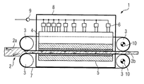
図1に生産機械1を示す。この生産機械1は木質材料用連続プレスである。生産機械1は4つのローラ3を有し、ローラは恒常的又は歩進的圧縮成形によって圧延材2を加工する。圧延材は特に木材であり、符号2aは圧延材又は加工品の出発状態を示す。符号2bは圧延材を最終状態の製品として示す。木質材料用のこのような連続プレスにより、例えば圧縮ボード又はパーティクルボードが製造できる。
FIG. 1 shows a production machine 1. This production machine 1 is a continuous press for wood materials. The production machine 1 has four
プレスプレート4とプレステーブル5がローラ3と共に圧延材2を成形する。プレスプレート4はプレスシリンダ6で駆動される。このプレスシリンダ6は、例えば液圧式又は空圧式でよい。4つのローラ3の内、2つはローラ用の電気的直接駆動装置10で駆動され、トルクは鋼帯7により残り2つのローラ3に伝達される。プレスシリンダ6は管路とポンプ9を介して例えば油を供給される。更に図示のハウジング8が生産機械1のハウジングを形成する。図1は略図にすぎず、木質材料用連続プレスの基本原理のみを示す。
The
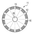
図2に示すディスク状一次部品11は、支持板又は基板15を有する。支持板15に、複数の湾曲状一次部品要素又は一次部品セグメント12が配置されている。図2の実施例では、例えば12個の一次部品要素12が配置されている。各一次部品要素12が個別の三相巻線16を有し、この巻線は、特に界磁コイルとも称される歯巻回コイルによって形成されている。図2によれば、ディスク半径に相応する最大数の一次部品セグメント12が支持板15上に配置されている。しかし湾曲状一次部品セグメント12の代わりに、従来のリニアモータから公知の、直線状一次部品セグメントを配置することも可能である。一次部品11は中心に切欠き部20を備え、一次部品11は軸に配置可能である。
The disc-shaped
図3は一次部品11の他の構成を示す。図3に示す如く、少数の一次部品セグメント又は一次部品要素12が支持板15に配置されている。図3の実施例では、例えば6つの一次部品要素12が配置されており、図2と異なりディスク半径に相応して最大可能な数の半分の一次部品要素12が設けられている。それと共、図2とは異なり、発生可能なトルク又は発生可能な出力は約50%減少している。加えて個別の一次部品要素12を使用することで、所望の出力密度又はトルクに応じて一次部品要素12の数を変更できる。
FIG. 3 shows another configuration of the
図4は二次部品13の実施形態を示す。二次部品13は複数の、この例では合計12個の二次部品要素14を備える。二次部品要素14は互いに接合されて環或いは円を形成する。二次部品要素14で、極力閉鎖環又は円を形成すると望ましい。さもないと、二次部品要素14間の過大な距離の故に高いコギングトルクが発生する結果となる。二次部品要素14は一方でやはり支持板上に配置しておける。選択的に、二次部品要素14によって形成される環は控え又は棒で切欠き部20の(図示しない)軸受で支承できる。
FIG. 4 shows an embodiment of the
各二次部品要素14が例えば3つの永久磁石17を有し、各永久磁石17は単部分又は多部分で構成できる。各永久磁石17は直方体状に形成されており、永久磁石17は、特に円形配置となるように特定の相互角度で配置されている。
Each
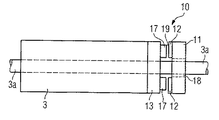
図5は、ローラ用電気的直接駆動装置10をローラ3に機械技術的に結合する第1構成例を示す。ローラ3は駆動軸3aに配置されている。直接駆動装置10はディスクモータとして形成され、ディスク状一次部品11とディスク状二次部品13を有する。一次部品と二次部品はディスク状又は環状空隙19で相互に離間している。電磁力又は電磁界は軸線方向において駆動軸3aと平行に一次部品11と二次部品13の間で作用する。二次部品13に永久磁石17が、一次部品11に一次部品要素12が各々配置されている。
FIG. 5 shows a first configuration example in which the roller electrical
二次部品13は可動部材、即ちロータとして形成され、ローラ3に直接結合、即ちローラ3の正面に直接配置されている。二次部品13は例えば嵌合式、摩擦接合式又は素材接合式にローラに固着できる。二次部品13はローラ3に、例えば螺着、溶接又は接着されている。二次部品13をローラ3にこのように配置することで、トルクはローラ3に直接伝達される。一次部品11は定置部品、即ちステータとして形成され、軸3aに配置されている。一次部品11は、例えば転がり軸受又は滑り軸受として形成できる軸受装置18によって配置されている。定置一次部品11は他の定置構成部品で支承し得るが、そのことは図示していない。例えば一次部品をトルク控えによって生産機械のハウジング部品に結合することができる。
The
図6はローラの電気的直接駆動装置10をローラ3に機械技術的に結合する他の構成を示す。この実施形態では、事実上2つの直接駆動装置10が軸3aに配置されている。2つの一次部品11と2つの二次部品13が軸線方向に並べて配置されている。ローラ3の駆動軸3aに伝達されるトルクはこうして倍になる。所望の出力又はトルクに応じ、任意数のディスクモータを電気的直接駆動装置として配置できる。
FIG. 6 shows another arrangement for mechanically coupling the roller electrical
図7はローラの直接駆動装置10の他の実施形態を示す。この実施形態では、駆動装置10が所謂二重櫛形配置として形成されている。一次部品11が軸3aに配置され、支持板15の各側に一次部品要素12が配置されている。一次部品11の両側に各々配置された二次部品13は、定置でハウジング又は機械構造体で支承されている。
FIG. 7 shows another embodiment of the roller
二次部品13は両側に二次部品要素14を装備し、駆動軸3aと強固に結合することもできる。二次部品13の両側で相応に装備された一次部品11は、両方の一次部品11を結合するハウジングを介して、二次部品13に対し定置式に機械構造体と結合される。
The
3 ローラ、3a 駆動軸、10 直接駆動装置、11 一次部品、12 一次部品要素、13 二次部品、14 二次部品要素、17 永久磁石、19 空隙 3 Roller, 3a Drive shaft, 10 Direct drive device, 11 Primary part, 12 Primary part element, 13 Secondary part, 14 Secondary part element, 17 Permanent magnet, 19 Air gap
Claims (11)
Applications Claiming Priority (2)
| Application Number | Priority Date | Filing Date | Title |
|---|---|---|---|
| EP07022398.7 | 2007-11-19 | ||
| EP07022398A EP2061136A1 (en) | 2007-11-19 | 2007-11-19 | Electric direct drive for a roller |
Publications (3)
| Publication Number | Publication Date |
|---|---|
| JP2009131147A true JP2009131147A (en) | 2009-06-11 |
| JP2009131147A6 JP2009131147A6 (en) | 2009-08-13 |
| JP2009131147A5 JP2009131147A5 (en) | 2012-01-05 |
Family
ID=39186859
Family Applications (1)
| Application Number | Title | Priority Date | Filing Date |
|---|---|---|---|
| JP2008293578A Pending JP2009131147A (en) | 2007-11-19 | 2008-11-17 | Electrical direct drive for roller |
Country Status (4)
| Country | Link |
|---|---|
| US (1) | US8102095B2 (en) |
| EP (1) | EP2061136A1 (en) |
| JP (1) | JP2009131147A (en) |
| CN (1) | CN101442243B (en) |
Families Citing this family (7)
| Publication number | Priority date | Publication date | Assignee | Title |
|---|---|---|---|---|
| DE102009059116A1 (en) * | 2009-12-18 | 2012-02-02 | Continental Automotive Gmbh | electric motor |
| ES2600639T3 (en) | 2013-05-29 | 2017-02-10 | Kverneland A/S | Work unit suitable for use in an agricultural machine and agricultural machine |
| CN104558058B (en) | 2013-10-12 | 2017-08-08 | 中国科学院长春应用化学研究所 | Metallocene complex and preparation method thereof, carbon monoxide-olefin polymeric |
| DE102014219474B4 (en) | 2014-09-25 | 2022-06-09 | Valeo Siemens Eautomotive Germany Gmbh | Process for operating power semiconductors |
| US9688473B2 (en) | 2015-03-02 | 2017-06-27 | Lorin Reed | Conveying systems and methods of use |
| WO2017123441A1 (en) | 2016-01-11 | 2017-07-20 | Laitram, L.L.C. | Motorized pulley and belt drive system |
| NZ765295A (en) | 2017-11-22 | 2023-02-24 | Lorin REED | Improved produce conveying and sizing equipment |
Citations (4)
| Publication number | Priority date | Publication date | Assignee | Title |
|---|---|---|---|---|
| JPH1017245A (en) * | 1996-06-28 | 1998-01-20 | Mitsubishi Electric Corp | Hoist for elevator |
| WO2001086781A1 (en) * | 2000-05-05 | 2001-11-15 | Abb Research Ltd | Roll drive for moving rolls |
| JP2007028854A (en) * | 2005-07-20 | 2007-02-01 | Yamaha Motor Co Ltd | Rotary electric machine and electric wheelchair |
| JP2007124884A (en) * | 2005-09-30 | 2007-05-17 | Hitachi Industrial Equipment Systems Co Ltd | Claw pole type rotary electric machine |
Family Cites Families (12)
| Publication number | Priority date | Publication date | Assignee | Title |
|---|---|---|---|---|
| CA1004274A (en) * | 1974-04-04 | 1977-01-25 | Canadian General Electric Company Limited | Permanent magnet hermetic synchronous motor |
| EP0548362B1 (en) * | 1991-07-11 | 1997-09-03 | Secoh Giken, Inc. | Flat coreless dc motor |
| US5334899A (en) * | 1991-09-30 | 1994-08-02 | Dymytro Skybyk | Polyphase brushless DC and AC synchronous machines |
| US6348751B1 (en) * | 1997-12-12 | 2002-02-19 | New Generation Motors Corporation | Electric motor with active hysteresis-based control of winding currents and/or having an efficient stator winding arrangement and/or adjustable air gap |
| US6710505B1 (en) * | 1998-06-11 | 2004-03-23 | Aspen Motion Technologies, Inc. | Direct drive inside-out brushless roller motor |
| CN2354292Y (en) * | 1998-09-23 | 1999-12-15 | 吴智文 | Disc-type ac. motor |
| FI120104B (en) * | 2000-05-05 | 2009-06-30 | Abb Research Ltd | roller drive |
| JP2005171835A (en) * | 2003-12-10 | 2005-06-30 | Fujitsu General Ltd | Blower |
| DE102004034636A1 (en) * | 2004-07-16 | 2006-02-16 | Bosch Rexroth Ag | Direct drive with rotary encoder |
| US20060022552A1 (en) * | 2004-07-28 | 2006-02-02 | Silicon Valley Micro M Corporation | Multi-phase A.C. vehicle motor |
| CN2779711Y (en) * | 2004-12-08 | 2006-05-10 | 张天龙 | Unit laminated type totally-enclosed DC motor |
| DE102006013636B4 (en) * | 2006-03-22 | 2012-02-09 | Siemens Ag | Printing machine or electric machine for a printing press |
-
2007
- 2007-11-19 EP EP07022398A patent/EP2061136A1/en not_active Ceased
-
2008
- 2008-11-17 JP JP2008293578A patent/JP2009131147A/en active Pending
- 2008-11-18 US US12/273,221 patent/US8102095B2/en not_active Expired - Fee Related
- 2008-11-19 CN CN2008101770588A patent/CN101442243B/en not_active Expired - Fee Related
Patent Citations (4)
| Publication number | Priority date | Publication date | Assignee | Title |
|---|---|---|---|---|
| JPH1017245A (en) * | 1996-06-28 | 1998-01-20 | Mitsubishi Electric Corp | Hoist for elevator |
| WO2001086781A1 (en) * | 2000-05-05 | 2001-11-15 | Abb Research Ltd | Roll drive for moving rolls |
| JP2007028854A (en) * | 2005-07-20 | 2007-02-01 | Yamaha Motor Co Ltd | Rotary electric machine and electric wheelchair |
| JP2007124884A (en) * | 2005-09-30 | 2007-05-17 | Hitachi Industrial Equipment Systems Co Ltd | Claw pole type rotary electric machine |
Also Published As
| Publication number | Publication date |
|---|---|
| US8102095B2 (en) | 2012-01-24 |
| US20090127959A1 (en) | 2009-05-21 |
| CN101442243B (en) | 2013-10-30 |
| CN101442243A (en) | 2009-05-27 |
| EP2061136A1 (en) | 2009-05-20 |
Similar Documents
| Publication | Publication Date | Title |
|---|---|---|
| EP3176931B1 (en) | Winding type permanent magnet coupling transmission device | |
| JP2009131147A (en) | Electrical direct drive for roller | |
| EP3298678B1 (en) | Method of construction for permanent magnet generator | |
| EP1460746A4 (en) | Axial gap type dynamo-electric machine | |
| US7375449B2 (en) | Optimized modular electrical machine using permanent magnets | |
| JP2009131147A6 (en) | Electrical direct drive for rollers | |
| JP2010517498A (en) | Rotation drive with linear primary part segment | |
| CN102104303A (en) | Disc-type low-speed large-torque composite motor based on magnetic wheel gear | |
| CN101924436B (en) | Axial magnetic field modulated brushless double rotor motor | |
| US20090218900A1 (en) | Permanent Magnet Alternator with Segmented Construction | |
| US20060192453A1 (en) | Modular transverse flux motor with integrated brake | |
| US20070138893A1 (en) | Rotor assembly for use in line start permanent magnet synchronous motor | |
| US10476349B2 (en) | Method and apparatus for compact axial flux magnetically geared machines | |
| JP2008141853A (en) | Biaxial concentric motor | |
| US20100013346A1 (en) | Low speed, permanent magnet brushless motors and generators | |
| US20120139368A1 (en) | Pulsed multi-rotor constant air gap motor cluster | |
| CN101789646B (en) | Multivariant linear arc-shaped motor | |
| KR20160117616A (en) | Permanent magnet rotating electric machine | |
| CN101951047A (en) | Disk permanent magnet composite brushless motor | |
| CN108964389B (en) | Low-voltage high-power axial combined disc type permanent magnet motor | |
| CN1055181C (en) | Unyoked slotless axial magnetic circuit motor | |
| CN202405972U (en) | Disc-type permanent magnet cursor motor | |
| US9035530B2 (en) | Energy converting device having an eccentric rotor | |
| CN102570751A (en) | Disk type permanent-magnet cursor motor | |
| KR100787313B1 (en) | An apparatus comprising modular transverse flux rotary electric machines and a method of providing the same |
Legal Events
| Date | Code | Title | Description |
|---|---|---|---|
| A521 | Written amendment |
Free format text: JAPANESE INTERMEDIATE CODE: A523 Effective date: 20111111 |
|
| A621 | Written request for application examination |
Free format text: JAPANESE INTERMEDIATE CODE: A621 Effective date: 20111111 |
|
| RD03 | Notification of appointment of power of attorney |
Free format text: JAPANESE INTERMEDIATE CODE: A7423 Effective date: 20111111 |
|
| A131 | Notification of reasons for refusal |
Free format text: JAPANESE INTERMEDIATE CODE: A131 Effective date: 20130521 |
|
| A521 | Written amendment |
Free format text: JAPANESE INTERMEDIATE CODE: A523 Effective date: 20130625 |
|
| A02 | Decision of refusal |
Free format text: JAPANESE INTERMEDIATE CODE: A02 Effective date: 20131119 |