JP2009128689A - Projection display apparatus - Google Patents
Projection display apparatus Download PDFInfo
- Publication number
- JP2009128689A JP2009128689A JP2007304435A JP2007304435A JP2009128689A JP 2009128689 A JP2009128689 A JP 2009128689A JP 2007304435 A JP2007304435 A JP 2007304435A JP 2007304435 A JP2007304435 A JP 2007304435A JP 2009128689 A JP2009128689 A JP 2009128689A
- Authority
- JP
- Japan
- Prior art keywords
- light
- light source
- projection
- illumination
- display device
- Prior art date
- Legal status (The legal status is an assumption and is not a legal conclusion. Google has not performed a legal analysis and makes no representation as to the accuracy of the status listed.)
- Granted
Links
Images


Abstract
Description
本発明は、ライトバルブにより変調された照明光束を空間あるいはスクリーン上に投射して表示画像を得る投射型表示装置に関する。 The present invention relates to a projection display device that obtains a display image by projecting an illumination light beam modulated by a light valve onto a space or a screen.
液晶パネルなどの矩形の投射画面をスクリーン上に投射して、表示画像を得る投射型表示装置として、液晶プロジェクタが知られている。このような投射型表示装置(以下、投射装置と略称することがある。)における光源装置は、単一の光源だけでなく複数の光源を組み合わせたものが各種知られている。 A liquid crystal projector is known as a projection display device that obtains a display image by projecting a rectangular projection screen such as a liquid crystal panel on a screen. Various types of light source devices in such a projection type display device (hereinafter sometimes abbreviated as “projection device”) are not only a single light source but also a combination of a plurality of light sources.
例えば、特許文献1には、図9に示すように、2つの光源からの光をひとつの光束として射出する光源装置であって、2つの光軸10a,10bを直交させて配置した放物面の2つの主鏡(放物面鏡)2a,2bと、それぞれの主鏡2a,2bの焦点に各々配置された2つのランプ(光源)1a,1bと、主鏡2a,2bの開口の半分を塞ぐ平面の2つの副鏡(平面鏡)3d,3eと、端部が主鏡2a,2bの光軸10a,10bの交点に接し、両光軸10a,10bに対して45゜傾けて配置した平面鏡20で構成された光源装置が開示されている。主鏡2a,2bの開口のうち副鏡3d,3eが覆っている部分で反射された主鏡2a,2bからの光は、副鏡3d,3eによってほぼ垂直に反射され、主鏡2a,2bの同一部位で再反射されて、焦点を通って主鏡2a,2bの反対側の部位に入射し、ここに直接入射するランプからの光と共に、断面が半円形の平行光束として射出される。副鏡3d,3eは主鏡2a,2bから射出された光束の一方を反射し他方を直進させることにより、両光束を繋ぎ合わせて断面が円形となるひとつの光束となっている。
For example,
特許文献2には、複数個の光源と、複数個の光源からの光を合成する光合成部と、光合成部からの光の偏光方向を揃える偏光変換素子と、偏光変換素子からの光の照度を均一化し、且つ第1のレンズアレイと第2のレンズアレイとで形成されるレンズアレイ群と、レンズアレイ群からの光をR光、G光及びB光の各色の光に分離する色分離部と、色分離部で分離された3原色の各々の色に対応して配置された複数個の映像表示素子と、複数個の映像表示素子からの光を合成する色合成部と、色合成部からの光を投射する投射レンズとで構成された投射装置が開示されている。照明光の光合成部は、図10に示すように、入射した光のうち、約半分の光を透過し、残りの半分の光を反射する光分離部であるハーフミラー3aと、全反射ミラー3bとからなる。詳細に述べるならば、光合成部は、断面が直角三角形のブロック状の透光性部材と、断面が平行四辺形のブロック状の透光性部材とを貼り合わせたプリズムアレイ構成となっている。そして、それらの接合界面にハーフミラー膜としての作用面3aが形成され、また平行四辺形の透光性部材の外部斜面に全反射膜としての作用面3bが形成されている。このようにして、光源1aと光源1bの光束を合成して、インテグレータ光学系に入射している。
In Patent Document 2, a plurality of light sources, a light combining unit that combines light from the plurality of light sources, a polarization conversion element that aligns the polarization direction of light from the light combining unit, and the illuminance of light from the polarization conversion element are described. A lens array group that is uniformized and formed by the first lens array and the second lens array, and a color separation unit that separates light from the lens array group into light of each color of R light, G light, and B light A plurality of video display elements arranged corresponding to each of the three primary colors separated by the color separation unit, a color synthesis unit for synthesizing light from the plurality of video display elements, and a color synthesis unit The projection apparatus comprised by the projection lens which projects the light from is disclosed. As shown in FIG. 10, the light combining unit of the illumination light includes a
特許文献3,4に開示されているカラー液晶プロジェクタにおける光源装置は、図11,12に示すように、4灯式及び2灯式の光源装置であるが、特許文献1,2とはその配置が相違しており、個々の光源装置(ランプ及び反射鏡の組み合わせ)の照射する光束の光軸は同一方向に揃っている。なお、特許文献3における光源装置の照射する光は平行光束であるが、特許文献4における光源装置の照射する光は集光光束である。しかし、両者とも光源装置の照射する光の光軸は、同一直線状又は平行線上にある。 The light source device in the color liquid crystal projector disclosed in Patent Documents 3 and 4 is a four-lamp type or two-lamp type light source device as shown in FIGS. Are different, and the optical axes of the light beams irradiated by the individual light source devices (the combination of the lamp and the reflecting mirror) are aligned in the same direction. In addition, although the light irradiated by the light source device in Patent Document 3 is a parallel light beam, the light irradiated by the light source device in Patent Document 4 is a condensed light beam. However, in both cases, the optical axes of light emitted from the light source device are on the same straight line or parallel lines.
しかし、特許文献3,4に開示されているカラー液晶プロジェクタにおいては、この液晶プロジェクタが投射する表示画像の水平方向(本願においては、表示画面を観察したときに横方向と認識する方向、すなわち通常の矩形の表示画面を垂直なスクリーンに投射したときの横方向を水平方向という。また、水平方向の線を水平線という。)と光源装置から発する光束の光軸との配置関係は記載されていないので、どのような関係かは不明である。例えば、図11で説明すれば、この液晶プロジェクタは、紙面の表側と裏側を液晶プロジェクタの上下と見立てれば、紙面の左右方向が表示画像7の水平方向となり、光源装置から発する光束の光軸は表示画像7の水平方向と平行である。ところが、紙面の左側と右側を液晶プロジェクタの上下と見立てれば、紙面に垂直な方向が表示画像7の水平方向となり、光源装置から発する光束の光軸は表示画像の水平方向と垂直となる。このように、図11,12においては、液晶プロジェクタが投射する表示画像の水平方向と光源装置から発する光束の光軸との配置関係は特定されていない。 However, in the color liquid crystal projectors disclosed in Patent Documents 3 and 4, the horizontal direction of the display image projected by the liquid crystal projector (in this application, the direction recognized as the horizontal direction when the display screen is observed, that is, the normal direction) The horizontal direction when a rectangular display screen is projected onto a vertical screen is referred to as the horizontal direction, and the horizontal line is referred to as the horizontal line.) And the optical axis of the luminous flux emitted from the light source device are not described. So it is unclear what kind of relationship it is. For example, referring to FIG. 11, in this liquid crystal projector, assuming that the front and back sides of the paper are the top and bottom of the liquid crystal projector, the horizontal direction of the paper is the horizontal direction of the display image 7, and the optical axis of the light beam emitted from the light source device Is parallel to the horizontal direction of the display image 7. However, assuming that the left and right sides of the paper are the top and bottom of the liquid crystal projector, the direction perpendicular to the paper is the horizontal direction of the display image 7, and the optical axis of the light beam emitted from the light source device is perpendicular to the horizontal direction of the display image. Thus, in FIGS. 11 and 12, the positional relationship between the horizontal direction of the display image projected by the liquid crystal projector and the optical axis of the light beam emitted from the light source device is not specified.
ところで、一般に、高圧水銀ランプなどのアーク放電型のランプは、特に、プロジェクタなどへ適用されているランプは、アーク近傍の温度が数百度から1000度を越えるといわれており、ランプメーカは、安定した点灯を実現するために、リフレクタ−(反射鏡)を取りつけたときの形態でランプ構造の最適化設計を行っている。例えば、特許文献5の段落[0016]中の従来技術の問題点にも記載されている内容によると「放電ランプは、陽極と陰極との間におけるアーク放電により、内部に封入されている水銀、あるいは、不活性ガスの原子や分子が励起されて発光されるものである。したがって、光源を構成する放電ランプが水平方向に対し傾けられて配置されると、両電極の水平方向からの傾きにより、アーク放電パターンに影響を与えてしまい、結果、両電極にストレスとなるダメージが与えられ、放電ランプの寿命を短くしてしまう問題を有している。而して、一般に、放電ランプを使用する光源の水平方向からの傾斜角度θ2は、20度以下に抑えて使用されることが求められている。」とあり、放電ランプのアーク軸が水平からずれることの不具合を示すことが記されている。放電ランプ以外の光源においても、上述の作用効果は大なり小なり見受けられる。また、一般に光源装置においては、光源から発する光束の光軸と放電ランプのアーク軸とは、製作上の容易さ、発光光の有効利用などの観点から同軸又は平行軸としていると考えてよい。なお、放電ランプのアーク軸とは、放電ランプにおける陽極と陰極とを結ぶ軸線である。
最近の液晶プロジェクタは、投射光量を増加して、より大画面で、より明るい表示画面を達成するため、個々の放電ランプの光量を増加させることが要求されている。一般に、放電ランプの光を有効利用するために、放電ランプは光源の一方を放物面鏡や回転楕円鏡で覆い、他方に開口を設けて平行光や集光を射出する構造になっている。そして、放電ランプの光軸は、放電ランプが照射する平行光や集光の光軸と平行になるように構成されている。そこで、光源の光量を増加させるためには、放電ランプに大量の電力が投入され、発行量を増加される。しかし、放電ランプに大量の電力が投入されると、放電ランプの温度が上がりやすく、放電ランプの寿命や性能維持の面からアーク軸を水平に保つことがより重要になる。 Recent liquid crystal projectors are required to increase the light intensity of individual discharge lamps in order to increase the light intensity of projection and achieve a brighter display screen with a larger screen. In general, in order to effectively use the light of a discharge lamp, the discharge lamp has a structure in which one of the light sources is covered with a parabolic mirror or a spheroid mirror, and an opening is provided on the other to emit parallel light or condensed light. . The optical axis of the discharge lamp is configured to be parallel to the parallel light irradiated by the discharge lamp and the optical axis of light collection. Therefore, in order to increase the amount of light from the light source, a large amount of power is input to the discharge lamp to increase the amount of issuance. However, when a large amount of electric power is applied to the discharge lamp, the temperature of the discharge lamp tends to rise, and it becomes more important to keep the arc axis horizontal in terms of the life and performance maintenance of the discharge lamp.
投射装置の投射光量を増加する方法として、上記の特許文献1〜4に示したように、放電ランプの数を増やすことも考えられている。この場合も、光源全体の安定性や寿命の点から全ての放電ランプにおけるアーク軸を水平に保つことが求められる。すなわち、それぞれの光源からの照射光の光軸を水平とすることである。
As a method for increasing the amount of light projected by the projection device, it is also considered to increase the number of discharge lamps as shown in the above-mentioned
しかし、特許文献1,2に記載されているような照明装置では、2つの照射光の光軸が垂直になっており、照射光の光軸と同じ方向を向く光源ランプのアーク軸も垂直に交わっているけれども、これらの光軸が水平になっているという考え方は記載されていない。さらに、これらの光源を使用した液晶プロジェクタにおいては、偶然2つの光源からの光束の光軸が水平であったとしても、液晶プロジェクタそのものを水平に回転して使用する場合は問題ないが、この液晶プロジェクタで斜め上に画像を投影するために液晶プロジェクタを垂直方向に傾けると、少なくとも一方の光源からの光束の光軸は水平から傾いてしまい、当然アーク軸も傾いてしまう。
However, in the illumination device described in
また、特許文献3,4に記載されている液晶プロジェクタは、上述のように、表示画像の水平方向と光源からの光束の光軸が水平方向との配置関係が特定されておらず、この光源装置の光源からの光束の光軸は、表示画像の水平方向と垂直になっている可能性もある。すなわち、光源からの光束の光軸、言い換えれば、放電ランプのアーク軸を水平に保つという考え方はなく、そのような考慮も払われていない。 In addition, as described above, the liquid crystal projector described in Patent Documents 3 and 4 does not specify the positional relationship between the horizontal direction of the display image and the optical axis of the light beam from the light source. The optical axis of the light beam from the light source of the apparatus may be perpendicular to the horizontal direction of the display image. That is, there is no idea of keeping the optical axis of the light flux from the light source, in other words, the arc axis of the discharge lamp horizontal, and such consideration is not paid.
このように、従来の投射装置においては、放電ランプのアーク軸を水平に保つべきという問題点に対する考慮がなく、投射装置でほぼ正面の垂直な壁に表示画像を投射するときにおいても、斜め上方の壁や、極端な場合には天井や床面に表示画像を投射する場合にも放電ランプのアーク軸を水平に保って、放電ランプの寿命や性能維持を図ることは考えられていなかったし、そのような構成を特定する説明や図面の記載はなかった。 As described above, in the conventional projection apparatus, there is no consideration for the problem that the arc axis of the discharge lamp should be kept horizontal. Even when the display apparatus projects a display image on a substantially vertical vertical wall, it is obliquely upward. Even when projecting a display image on the wall or in extreme cases the ceiling or floor surface, it was not considered to maintain the discharge lamp life and performance by keeping the arc axis of the discharge lamp horizontal. There was no description or drawing to specify such a configuration.
特に、複数の光源を使用した投写装置においては、投写装置を水平に設置したときに複数の光源のアーク軸がたとえ水平に配置されていたとしても、投射方向を上下に移動してもすべての光源のアーク軸が水平に保たれているものはなかった。この為、投写装置の使用中の投射姿勢により、一部又は全部の光源のアーク軸が水平から大きくずれることがあり、特に複数光源においては、光源の寿命低下や安定性不良という問題が解消されていなかった。 In particular, in a projection apparatus using a plurality of light sources, even if the arc axes of the plurality of light sources are arranged horizontally when the projection apparatus is installed horizontally, all projections are moved up and down. None of the light source arc axes were kept horizontal. For this reason, the arc axis of some or all of the light sources may deviate greatly from the horizontal depending on the projection posture during use of the projection apparatus, and in particular, in the case of multiple light sources, the problems of reduced light source life and poor stability are solved. It wasn't.
本発明の目的は、上記課題を踏まえ、通常のどのような使用体勢においても、複数の光源を持ち、その全ての光源のアーク軸を水平に保つことのでき、光源の寿命や安定性を向上させた投写型表示装置を提供することである。 The object of the present invention is to have a plurality of light sources in any normal use posture, keeping the arc axis of all the light sources horizontal, and improving the life and stability of the light sources. And providing a projection display apparatus.
上記課題を解決するため本発明者等は、以下の発明を完成した。
本発明は、光源から発する光を反射鏡で略平行光にして又は集光して得られた光源光束を形成する複数の光源装置と、前記複数の光源装置からの光源光束を纏めて照明光束とする照明光学系と、前記照明光束に照明されるライトバルブと、前記ライトバルブにより変調された光束を空間あるいはスクリーン上に投射して表示画像を結像させる結像光学系とを備えた投射型表示装置において、前記空間あるいはスクリーン上に投射された画像における水平方向と、前記複数の光源装置における光源光束の光軸とが平行であることを特徴とする投射型表示装置である。
In order to solve the above problems, the present inventors have completed the following invention.
The present invention includes a plurality of light source devices that form a light source light beam obtained by making light emitted from a light source substantially parallel or condensed by a reflecting mirror, and a light source light beam from the plurality of light source devices. Projection comprising: an illumination optical system; a light valve illuminated by the illumination light beam; and an imaging optical system for projecting the light beam modulated by the light valve onto a space or a screen to form a display image In the type display device, the horizontal direction in the image projected on the space or the screen is parallel to the optical axis of the light source luminous flux in the plurality of light source devices.
好ましい本発明は、前記光源装置の光源がアーク放電型ランプであり、該アーク放電型ランプのアーク軸を光源光束の光軸と平行に配置したことを特徴とする前記投射型表示装置である。 In a preferred aspect of the present invention, the light source of the light source device is an arc discharge lamp, and the arc axis of the arc discharge lamp is arranged in parallel to the optical axis of the light source luminous flux.
好ましい本発明は、前記反射鏡が放物面鏡であり、光源の発光部を前記放物面鏡の焦点に配置することを特徴とする前記投射型表示装置である。 In a preferred aspect of the present invention, the projection type display device is characterized in that the reflecting mirror is a parabolic mirror, and a light emitting portion of a light source is disposed at a focal point of the parabolic mirror.
好ましい本発明は、前記放物面鏡で反射された光の一部光路中に反射鏡を配置し、前記放物面鏡で反射された光の一部を再び放物面鏡に導き、光源光束とすることを特徴とする前記投射型表示装置である。 In a preferred aspect of the present invention, a reflecting mirror is disposed in a part of an optical path of light reflected by the parabolic mirror, a part of the light reflected by the parabolic mirror is again guided to the parabolic mirror, and a light source The projection display apparatus is characterized in that a light beam is used.
好ましい本発明は、前記反射鏡が回転楕円鏡であり、光源の発光部を前記回転楕円鏡の何れか一方の焦点に配置すること特徴とする前記投射型表示装置である。 In a preferred aspect of the present invention, the reflection type mirror is a spheroid mirror, and the light emitting portion of the light source is arranged at one of the focal points of the spheroid mirror.
好ましい本発明は、前記回転楕円鏡で反射された光の光路中にパワーを有する集光素子を配置して、前記回転楕円鏡の開口幅より小さい光束幅の平行光束を形成したことを特徴とする前記投射型表示装置である。 In a preferred aspect of the present invention, a condensing element having power is arranged in an optical path of the light reflected by the spheroid mirror to form a parallel beam having a beam width smaller than the aperture width of the spheroid mirror. The projection display device.
好ましい本発明は、前記照明光学系が、前記複数の光源装置からの光源光束を結合させて照明光束とすることを特徴とする前記投射型表示装置である。 In a preferred aspect of the present invention, the illumination optical system combines the light source light beams from the plurality of light source devices to form an illumination light beam.
好ましい本発明は、前記複数の光源装置から得られるおのおのの光源光束を、光路分離素子により反射光と透過光とに分離し、それぞれ異なった光源光束からの反射光と透過光とを重畳させて複数の照明光束を形成したことを特徴とする前記投射型表示装置である。 In a preferred embodiment of the present invention, each light source beam obtained from the plurality of light source devices is separated into reflected light and transmitted light by an optical path separation element, and reflected light and transmitted light from different light source beams are superimposed on each other. The projection display device characterized in that a plurality of illumination light beams are formed.
好ましい本発明は、前記複数の光源装置の光源を個別に点滅させる光源制御装置を備えたことを特徴とする前記投射型表示装置である。 A preferable aspect of the present invention is the projection display device including a light source control device that individually blinks the light sources of the plurality of light source devices.
好ましい本発明は、前記複数の光源装置が、光源の出力が異なるものを含むことを特徴とする前記投射型表示装置である。 In a preferred aspect of the present invention, the projection display device is characterized in that the plurality of light source devices include ones having different light source outputs.
本発明は、光束を発生する第一及び第二の光源装置と、第一及び第二の光源装置で発生した光束を照明光束としてライトバルブに導く照明光学系と、前記ライトバルブに形成された画像を結像光学系により空間あるいはスクリーン上に結像させて表示画像を得る投射型表示装置において、上記複数の第一及び第二の光源装置における照明光源はアーク放電型ランプであり、前記表示画像における横方向を水平に保ったまま、投射表示装置の姿勢を変化させても、前記アーク放電型ランプのアーク軸は、水平に維持されていることを特徴とする投射型表示装置である。 The present invention is formed in the light valve, the first and second light source devices that generate a light beam, the illumination optical system that guides the light beam generated by the first and second light source devices to the light valve as an illumination light beam, and the light valve. In the projection display device that obtains a display image by forming an image on a space or a screen by an imaging optical system, the illumination light source in the plurality of first and second light source devices is an arc discharge lamp, and the display Even if the posture of the projection display device is changed while keeping the horizontal direction in the image horizontal, the arc axis of the arc discharge lamp is maintained horizontal.
本発明によれば、通常のどのような使用体勢においても、複数の光源を持ち、その全ての光源のアーク軸を水平に保つことのでき、複数光源における光源の寿命低下や安定性不良という問題が解消される投写型表示装置を提供することができる。 According to the present invention, in any normal use posture, there are a plurality of light sources, the arc axes of all the light sources can be kept horizontal, and there is a problem that the life of the light sources in the plurality of light sources is reduced and the stability is poor. It is possible to provide a projection display device in which the problem is solved.
本発明の投射型表示装置は、光源から発する光を反射鏡で略平行光にして又は集光して得られた光源光束を形成する複数の光源装置と、前記複数の光源装置からの光源光束を纏めて照明光束とする照明光学系と、前記照明光束に照明されるライトバルブと、前記ライトバルブにより変調された光束を空間あるいはスクリーン上に投射して表示画像を結像させる結像光学系とを備えている。好ましくは、光源装置の光源は、アーク放電型ランプであり、該アーク放電型ランプのアーク軸を光源光束の光軸と平行に配置されている。そして、空間あるいはスクリーン上に投射された画像における水平方向と、前記複数の光源装置における光源光束の光軸とが平行になるように構成されている。 The projection display device of the present invention includes a plurality of light source devices that form a light source light beam obtained by condensing or condensing light emitted from a light source with a reflecting mirror, and a light source light beam from the plurality of light source devices. Optical system that collects the illumination light beam, a light valve illuminated by the illumination light beam, and an imaging optical system that forms a display image by projecting the light beam modulated by the light valve onto a space or a screen And. Preferably, the light source of the light source device is an arc discharge lamp, and the arc axis of the arc discharge lamp is arranged in parallel with the optical axis of the light source beam. And it is comprised so that the horizontal direction in the image projected on the space or the screen and the optical axis of the light source light beam in the plurality of light source devices may be parallel.
また、本発明の投射型表示装置は、少なくとも2つの光源装置を有し、それぞれの光源装置から発する光束の光軸は平行又は重なっている。そして、これらの光軸は、この投射装置により正面の垂直に配置したスクリーンに表示画像を投影するときには、表示画像の水平線と平行であるので水平になっている。さらに、この投射装置の投射方向を左右に回転して表示画面を移動させても、光源装置から発する光束の光軸は水平を保っている。また、この投射装置の投射方向を上下に動かして表示画面を移動させても、それぞれの光源装置から発する光束の光軸は水平を保っている。すなわち、光源装置から発する光束の光軸と同一方向のアーク軸は、この投射装置の投射方向を上下左右に変更しても常に水平を保つことができる。この為、光源装置のランプに不都合なストレスがかからず、ランプの寿命が延び、発光の安定性も保たれる。 The projection display device of the present invention has at least two light source devices, and the optical axes of light beams emitted from the respective light source devices are parallel or overlapped. These optical axes are horizontal because they are parallel to the horizontal line of the display image when the projection image is projected onto a screen vertically arranged by the projection device. Furthermore, even if the display screen is moved by rotating the projection direction of the projection device left and right, the optical axis of the light beam emitted from the light source device remains horizontal. Further, even if the display screen is moved by moving the projection direction of the projection device up and down, the optical axes of the light beams emitted from the respective light source devices remain horizontal. That is, the arc axis in the same direction as the optical axis of the light beam emitted from the light source device can always be kept horizontal even if the projection direction of the projection device is changed from top to bottom and left and right. Therefore, inconvenient stress is not applied to the lamp of the light source device, the life of the lamp is extended, and the light emission stability is maintained.
本発明を実施するための最良の実施形態を必要に応じて図面を参照にして説明する。なお、いわゆる当業者は特許請求の範囲内における本発明を変更・修正をして他の実施形態をなすことは容易であり、これらの変更・修正はこの特許請求の範囲に含まれるものであり、以下の説明はこの発明の好ましい形態における例であって、この特許請求の範囲を限定するものではない。 The best mode for carrying out the present invention will be described with reference to the drawings as necessary. Note that it is easy for a person skilled in the art to make other embodiments by changing or correcting the present invention within the scope of the claims, and these changes and modifications are included in the scope of the claims. The following description is an example of a preferred embodiment of the present invention, and does not limit the scope of the claims.
(実施形態1)
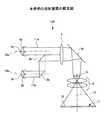
本発明の実施形態1の投射装置を図1に示した。この投射装置は、2つの光源装置を備え、折り返しミラー、照明レンズ系を含む照明光学系、ライトバルブ、投射レンズ系である結像光学系とを備えている。そして、この投射装置で特徴的なことは、2つの光源装置から発する平行光束の光軸が平行になるように配置され、さらに、この投射装置で投射した表示画像の水平方向の線と平行に構成されている。言い換えれば、2つの光源装置から発する平行光束の光軸は、一般に矩形である投射された表示画像の横方向と同じ方向を向いている。
(Embodiment 1)
The projection apparatus of
図1に従って、具体的に説明すると、この投射装置100における光源装置の光源1a,1bは、超高圧水銀ランプ、キセノンランプ、メタルハライドランプ、無電極放電ランプ等のアーク放電ランプ、LED、LD等の固体発光型光源など、さまざまな光源が用いられる。その中でもアーク放電ランプが好ましく用いられる。
Specifically, referring to FIG. 1, the
反射鏡2a,2bは、光源1a,1bから発散される光束を効率よく一方向に導くためのもので、いわゆるリフレクタとも呼ばれ、光源1a,1bと一体に形成され光源装置を形成している。光源装置は、電力供給用のリード線等が付属したランプハウスユニットとしての形態が一般的である。反射鏡2a,2bは、放物面鏡、回転楕円鏡などが好ましく用いられ、平行光や焦点への集光等の出射光が形成される。図1においては、それぞれ放電ランプ光源1a,1bと放物面鏡2a,2bを備えた2つの光源装置から光軸10a,10bが平行な光束11a,11bを出射している。
The reflecting mirrors 2a and 2b are used to efficiently guide light beams emitted from the
2つの光源装置から発生した平行な光束11a,11bのうち、一方の光束11bは折り返しミラー3a,3bにより平行移動され、もう一方の光束11aと接するように結合されひとつになる。そして、ひとつに結合された光束は照明レンズ系4、おり返しミラー3cにより光軸を90℃折り曲げられてライトバルブ5を照明する。これらの折り返しミラー3a,3b,3c、照明レンズ系4が照明光学系に相当する。
Of the
この実施形態の投射装置に搭載されている照明レンズ系4の具体例としては、フライアイレンズを組み合わせたいわゆるインテグレータ光学系などがある。その動作、作用としては、第一のフライアイレンズ光源光で複数の2次光源をつくり、第二フライアイレンズとコンデンサーレンズによって、ライトバルブ5上に重畳させて照明光の均一化を図っている。 As a specific example of the illumination lens system 4 mounted on the projection apparatus of this embodiment, there is a so-called integrator optical system combined with a fly-eye lens. As its operation and action, a plurality of secondary light sources are made with the first fly-eye lens light source light, and the second fly-eye lens and the condenser lens are superimposed on the light valve 5 to make the illumination light uniform. Yes.
ライトバルブ5を照明した照明光束は、ライトバルブ5により変調されて表示画像を形成する。ライトバルブ5としては、液晶ライトバルブ、反射型タイプや、透過型タイプ、また、微小なミラーを2次元配置したDMDといわれるライトバルブがあるが、これらは何れも採用可能である。特に、液晶ライトバルブでは、光の偏光を利用するために、照明光には一方向に揃えた直線偏光が望ましい。その場合は、必要に応じて、ランダム偏光の光源光を直線偏光に変換する、いわゆる偏光変換素子と組み合わせることもできる。 The illumination light beam that illuminates the light valve 5 is modulated by the light valve 5 to form a display image. Examples of the light valve 5 include a liquid crystal light valve, a reflection type, a transmission type, and a light valve called DMD in which minute mirrors are two-dimensionally arranged. Any of these can be employed. In particular, in a liquid crystal light valve, in order to use polarized light, linearly polarized light aligned in one direction is desirable for illumination light. In that case, if necessary, it can be combined with a so-called polarization conversion element that converts randomly polarized light source light into linearly polarized light.
ライトバルブ5上に表示された画像情報は、制御装置(図示せず)から入力された画像情報信号によって変調されて、照明光により結像光学系6(一般に投射レンズと呼ばれている)を介して拡大投射されスクリーン上に表示画像7を形成する。このとき、表示画像7は、通常は矩形であり、水平方向(横方向)と垂直方向(縦方向)を有している。ここで、水平方向とは、例えば、4:3のアスペクト比の矩形パネルであれば、長さ比4の方向、16:9のアスペクト比の矩形画面であるならば、長さ比16の長軸方向がセッティングされる。もちろん、使用用途に応じて、観察者が水平方向として選択した方向であればその方向を水平方向と定義する。 Image information displayed on the light valve 5 is modulated by an image information signal input from a control device (not shown), and the imaging optical system 6 (generally called a projection lens) is illuminated with illumination light. And a projected image 7 is formed on the screen. At this time, the display image 7 is usually rectangular and has a horizontal direction (lateral direction) and a vertical direction (vertical direction). Here, the horizontal direction is, for example, a rectangular panel having an aspect ratio of 4: 3, and a length ratio of 16 if the screen is a rectangular screen having an aspect ratio of 16: 9. The axial direction is set. Of course, the direction is defined as the horizontal direction if it is the direction selected by the observer as the horizontal direction according to the usage.
このとき、この実施形態の投射装置100は、結像光学系6から投射される投射光の光軸12は、光源装置から発した光束11a,11bの光軸10a,10bから90℃方向転換している。そして、この投射装置100においては、ライトバルブ5の姿勢を調整して、紙面の左右方向が表示画像の左右方向、すなわち表示画像の水平方向とし、紙面に対して垂直方向が表示画像の縦方向、すなわち垂直方向となるような構成にする。このような構成とすることで、光源装置から発した光束11a,11bの光軸10a,10bと表示画像の左右方向線、すなわち表示画像の水平線13とが平行になり、さらに、この投射装置100の投射方向を左右、又は上下に回転させても光源装置から発した光束11a,11bの光軸10a,10bは水平に保たれる。そして、光源10a,10bのアーク軸も水平に保たれる。投射装置100の通常の使用方法においては、投射装置100の左右方向と上下方向への回転は考えられるが、投射装置100の投射方向を軸として捩って使用することはないので、投射装置100の通常の使用状態においては、常に光源10a,10bのアーク軸は水平に保たれる。
At this time, in the
この状態を図2,3を参照にして説明すると、図2はこの実施形態の投射装置100により垂直なスクリーンに表示画像7を投射した斜視図である。表示画像7における水平線13は矩形の画像の上下端部の線に相当し、表示画像の垂直線14は画像の左右端部の線に相当する。そして、投射装置100の中の光源装置から発した光束11a,11bの光軸10a,10bは、点線表示しているが、表示画像の水平線13と平行になるため、水平線となっている。この投射装置100の投影方向を左右に回転させても、光軸10a,10bが水平を保たれることは容易に判る。
This state will be described with reference to FIGS. 2 and 3. FIG. 2 is a perspective view in which the display image 7 is projected onto a vertical screen by the
図3は、図2に示した投射装置100の投影方向を90℃上に向け、天井に表示画像7を結像させた斜視図である。この場合、投射装置100は、光軸10a、又は光軸10bを中心軸として90度回転したものと考えることができ、いずれにしても光軸10a,10bは水平を保っている。このように、この実施形態の投射装置100は、表示画像の水平線13(横方向)を水平に保ってさえいれば、常に光軸10a,10bは水平を保つことができる。
FIG. 3 is a perspective view in which the display image 7 is formed on the ceiling with the projection direction of the
なお、本願発明での水平とは厳密な意味での水平ではなく略水平であればよい。また、光軸10a,10bと表示画像の水平線13が平行との概念も略平行であればよい。これは、背景技術の欄の引用文献5で説明したように、アーク軸がほぼ水平を保つように投射装置100が構成されればよいからである。定量的には、水平とは、アーク軸の水平度として0度から20度くらいまでの範囲、望ましくは10度以内の誤差範囲内である。高温となるアーク放電型のランプでは、アーク軸が水平方向から傾けられて使用されると、両電極の水平方向からの傾きにより、アーク放電パターンに影響を与えてしまい、結果的に、放電ランプの寿命を短くしてしまう問題を有しているので、一般に、放電ランプを使用する光源1の水平方向からの傾斜角度θ2は、20度以下望、望ましくは10度以下に抑えて使用されることが求められており、この範囲に設定することが望ましいからである。このように、本願発明は、水平配置にすることを推奨された光源に適用した場合に最も効果を発揮する。特に、放電ランプ光源に適用することで、発光の安定や、発光寿命に関して非常に効果がある。なお、ここで、アーク軸とは、陽極と陰極を結ぶ線として定義している。
In addition, the horizontal in this invention should just be substantially horizontal not horizontal in a strict meaning. Further, the concept that the
(実施形態2)
本発明の実施形態2として、図4に例示したようなカラー投射装置を説明する。この投射装置100は、2つの光源光束を有していて、それぞれの光源光束11a,11bは、平板反射鏡(副鏡)3d',3e',3d,3eによって放物面鏡(主鏡)2a,2bの開口からの平行な光源光束の一部を放物面鏡2a,2bに戻されて、その光源光束の幅を狭めるのと同時に、放物面鏡(主鏡)2a,2b開口の周辺光の有効利用を行っている。
(Embodiment 2)
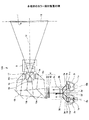
As a second embodiment of the present invention, a color projection apparatus as illustrated in FIG. 4 will be described. The
各々の光源光束11a,11bは、平板反射鏡3d',3e',3d,3eで形成される開口幅に応じた幅に狭められているが、2つの光源光束11a,11bのうち、一つは、折り返しミラー3a',3b'により光路を折り曲げ、また、もう一方は、折り返しミラー3a,3bにより光路を折り曲げられて、ちょうど隣接配置されているので、あたかも一つの照明光束となる。この照明光束を、インテグレータ光学系の照明レンズ系4で調整してライトバルブの照明光として用いている。
Each of the light source
照明光学系は、実施形態1で説明したようなインテグレータ光学系と偏光変換素子により透過型液晶のライトバルブ5a,5b,5c上に偏光のそろった均一照明がなされる。途中光路に、色分離素子15a,15bを組み合わせ、R,G,Bに対応した色分離を行ない、反射鏡16a,16b,16cを介してそれぞれの色に対応した3つのライトバルブ5a,5b,5cを照射する。各色対応した画像をライトバルブ5a,5b,5cで画像変調して、3つのライトバルブ5a,5b,5cから得られた画像は、色合成ブリズム17により合成されたあと、投射レンズ6により表示画像7を得る。
The illumination optical system performs uniform illumination with uniform polarization on the
ここで、光源1aから発し、第一の反射鏡2aで略平行になった光源光束11aの中心軸を光軸10a、光源1bから発し、第二の反射鏡2bで略平行になった光源光束11bの中心軸を光軸10bから発する。そして、光軸10a、10b、表示画像の水平線13(表示画像7の横方向線)は略平行となった配置で構成されている。このためには、光軸10a、10b平行になるように構成されており、投射レンズ6からの投射光の光軸12は光軸10a、10bと垂直に構成されている。そして、図4で言えば、紙面の上下方向が表示画像7の横方向(水平方向)であり、紙面に対して垂直な方向が表示画像7の縦方向である。このような構成で、表示画面の水平線13と、光軸10a、10bは互いに略平行となるような構成としているので、表示画面7の水平方向を保ったまま、例えば天井に投射画像を投射するなどしても、光軸10a、10bと平行なランプ光源のアーク軸は、水平から傾くことはない投射装置の姿勢を決めることができる。したがって、ランプ寿命が縮まるという問題点が解消されている。
Here, the central axis of the
(実施形態3)
実施形態3は、図5に示す投射装置である。この投射装置100は、実施形態2の投射装置と同様、平板反射鏡3d,3e,3fを用いて放物面鏡2a,2b,2cで反射した平行な光源光束の周辺光を光束の中央部に再帰反射させて照明効率を向上させているが。光源のランプを3つ利用した実施形態である。投射画像は図示していないが、3つの照明光束の光軸1a,1b,1cが、何れも投射画面7の水平方向と平行になっている。図示はしないが、このように光源が4つになっても、5つになってもそれぞれの光源光束の光軸が、投射画面7の水平方向(横方向)と平行になっていれば本発明の投射装置が実現できる。
(Embodiment 3)
Embodiment 3 is a projection apparatus shown in FIG. Similar to the projection apparatus of the second embodiment, the
また、光源が、アーク放電型ランプの場合は、アーク軸(陽極と陰極を結ぶ線上)が水平を保つことができる配置とする。通常、アーク放電型ランプのアーク軸と放物面鏡等で平行光となった光源光束の光軸は平行であるので、光源光束の光軸が水平であれば、実質的にアーク軸が水平となる。特殊な場合として、放物面鏡の焦点にアーク像が位置しているにもかかわらず、照明効率の観点で、アーク軸と光源光軸が正確に平行でない場合がある。この場合は、投射装置の姿勢を変化させても、アーク軸の方向と投射画面の水平方向(横方向)と平行に保つようにして、アーク軸を常に水平に保つことができるようにする。 When the light source is an arc discharge lamp, the arc axis (on the line connecting the anode and cathode) can be kept horizontal. Normally, since the arc axis of the arc discharge lamp and the optical axis of the light source beam that has become parallel light by a parabolic mirror or the like are parallel, if the optical axis of the light source beam is horizontal, the arc axis is substantially horizontal. It becomes. As a special case, although the arc image is located at the focal point of the parabolic mirror, the arc axis and the light source optical axis may not be exactly parallel from the viewpoint of illumination efficiency. In this case, even if the attitude of the projection apparatus is changed, the arc axis can be always kept horizontal by keeping the direction of the arc axis parallel to the horizontal direction (lateral direction) of the projection screen.
(実施形態4)
実施形態4の投射装置を図6に示した。図6に示す投射装置100は、平行に隣り合わせて配置した放物面鏡(主鏡)2a,2bの焦点に、光源1a,1bを配置し、第一平板反射鏡(副鏡)3d,3eを、放物面鏡2a,2bの前面に配置している。第一平板反射鏡3dは、ちょうど、放物面鏡2aから反射した平行反射光の開口上側半分を反射させ、再び光源近傍を通過させ、放物面鏡3aに再び反射されて、第一平板反射鏡3dがない開口部下部から光源光束11aとなって、照明光学系へと導かれる。同様に、第一平板反射鏡3eは、放物面鏡2bから反射した平行反射光の開口下側半分を反射させ、再び光源近傍を通過させ、放物面鏡3bに再び反射されて、第一平板反射鏡3eがない開口部上部から光源光束11bとなって、光源光束11aと隣り合わせの状態で照明光学系へと導かれる。
(Embodiment 4)
The projection device of Embodiment 4 is shown in FIG. The
図6に示すようにこの実施形態の投射装置100においても、照明光学系内部で光束の光路を90度変更し、投射レンズ6の投射光の光軸を光源光束11a,11bと垂直になるようにしている。そして、投射画像の水平方向を光源光束11a,11bの光軸に平行になるような構成レイアウトとしている。なお、表示画像7における水平方向は、図6の左右方向である。
As shown in FIG. 6, also in the
(実施形態5)
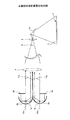
実施形態5の投射装置における照明装置を図7に示す。図7に示した照明装置は、これまで説明した放物面鏡の主鏡を利用して平行な光源光束を形成していた例と相違して、回転楕円面が有する2つの焦点のうち、一方の焦点に光源を配置して、回転楕円面から集光光束を得る。その集光光束中に、集光レンズ系(例えば、凹レンズ)を配置し、平行光束とし、その平行光束を照明光束として利用するものである。
(Embodiment 5)
An illumination device in the projection device of Embodiment 5 is shown in FIG. The illumination device shown in FIG. 7 differs from the example in which the parallel light source light beam is formed using the main mirror of the parabolic mirror described so far, of the two focal points of the spheroid, A light source is arranged at one focal point to obtain a condensed light beam from the spheroid. A condensing lens system (for example, a concave lens) is arranged in the condensed light beam to form a parallel light beam, and the parallel light beam is used as an illumination light beam.
図7を参照して具体的に説明すると、2組の光源装置を、光源1a,1bとそれに対応する回転楕円鏡2a,2bとで構成し、それぞれの光源装置からは集光光束が発生する。ここで、光源装置から発した2つの集光光束の光軸が平行になっており、従って、2つの光源1a,1bのアーク軸も平行になっている。
More specifically, referring to FIG. 7, two sets of light source devices are constituted by
光源装置から発した2つの集光光束は、それぞれ凹レンズ18A,18Bによって平行な光源光束11a,11bとなる。そして、2つの光源光束11a,11bは、折り返しミラー3a',3b'によってひとつの光束にされて、照明レンズ系4により照明光束として調整される。さらに、この照明光束は、図示していないが、光路を90度折り曲げられて、ライトバルブに照射され、ライトバルブで変調されて画像を形成され、投射レンズでスクリーン等に投射され表示画像を形成する。なお、光路を90度折り曲げるのは、照明光学系でなくても、投射レンズを含む結像光学系で実施してもよい。いずれにしても、スクリーン等に投射される表示画像の投射時点での投射光の光軸が、光源装置から発した2つの集光光束の光軸と90度の角度をなしている状態ならよい。
The two condensed light beams emitted from the light source device become parallel light source
(実施形態6)
実施形態6の投射装置を図8に示した。図8に示した投射装置100は、実施形態2で説明した図4に示すカラー投射装置と類似している。実施形態2との相違点は、2つの光源装置からの2つの光源光束11a,11bをひとつの照明光束とする構成にある。この実施形態の投射装置100は、放物面鏡2a,2bにより平行光とした平行光束の周辺部の光束のみを、平面反射鏡3d,3eで光源1a,1b近傍に戻し、再び、放物面鏡2a,2bにより反射させて光源光束11a,11bを得る。光源光束11aは、光路分離素子19の片面から入射して、透過光と反射光に分離される。このとき透過光をAT、反射光をARとする。一方、光源光束11bは、折り返しミラー3aを介して光路分離素子19の片面から入射して、透過光と反射光に分離される。このとき透過光をBT、反射光をBRとする。ここで、ATとBRとは一部もしくは、全部が重なり合うように配置されている。また、同時に、ARとBTが一部もしくは、全部が重なり合い、ARとBTとは、折り返しミラー3bにより、ATとBRと同じ方向に偏向し、照明光学系へと導かれる。
(Embodiment 6)
The projection apparatus of Embodiment 6 is shown in FIG. The
ここで、光源1aから発し、放物面鏡2aで略平行になった光源光束11aの中心軸である光軸10aと、光源1bから発し、放物面鏡2bで略平行になった光源光束11bの中心軸である光軸10bとは、平行な構成となっている。図8においては、2つの放物面鏡2a,2bは、略対向するように配置されているが、同じ方向を向いて並んでいてもよい。そして、この場合も、これらの光源光束11a,11bの放物面鏡から発する際の光軸10a,10bが、表示画像の水平方向に対して、ともに、略平行となった配置で構成されている。照明レンズ系4以降の構成は実施形態2と同じなので、説明を省略する。
Here, the
この実施形態においては。それぞれの光源装置から発した光源光束が重なり合って照明光学系に向かうので、一方の光源装置が故障したり、消灯されたり、減灯されたりしても全体の光量は低下するが、投射装置としては正常に投射画像を提供できる。また、2つの光源装置の光源の明るさが異なっていても投射される表示画面に光源に由来する明るさのムラができることはない。 In this embodiment. Since the light source beams emitted from each light source device overlap and go to the illumination optical system, even if one light source device breaks down, is turned off, or is turned off, the total amount of light decreases, but as a projection device Can provide a projected image normally. Further, even if the brightness of the light sources of the two light source devices is different, the brightness unevenness derived from the light source is not generated on the projected display screen.
(実施形態7)
実施形態7
これまで説明した実施形態1〜6においては、いずれも光源が2つ以上搭載されている実施例を示したが、この実施形態では、これらの光源が異なる出力の光源とした。表1に2つの光源を用いた場合について、その組み合わせに対する表示画面の明るさの変化を示した。
(Embodiment 7)
Embodiment 7
In

表1において、光源1は出力150Wを用い、光源2は出力100Wのもので組み合わせた場合を示す。両方の光源をonにした場合は、最も明るい出力が得られることは明白である。その次は、出力の高い光源1だけを点灯した場合、さらに、光源2のみを点灯した場合の3段階の明るさが得られることが判る。もし、同一の出力のランプを2つ組み合わせても、2段階の明るさ調整しかできない。このように、本発明の投射装置は、実施形態1〜6の殿形態においても、光源明るさを変化させることにより投射される表示画像の明るさを調整できる。このことを応用して、光源の一部が球切れ灯で消灯しても投射装置としては使用できることも判る。また、投射環境の状況に応じて表示画像の明るさを調整することもできる。
In Table 1, the
以上、説明した実施形態の投射装置の特徴点を列記すると、本発明の投射装置においては、投射された表示画像における水平方向に対し、第一の照明光束の光軸、第二の照明光束の光軸いずれもが略平行に配置されているので、表示画像の水平方向を保ったまま投射装置の姿勢を変えても、ランプの輝度安定性や、寿命を劣化させることがない。 As described above, when the characteristic points of the projection device of the embodiment described above are listed, in the projection device of the present invention, the optical axis of the first illumination light beam, the second illumination light beam, with respect to the horizontal direction in the projected display image. Since all the optical axes are arranged substantially in parallel, even if the attitude of the projection apparatus is changed while maintaining the horizontal direction of the display image, the luminance stability and life of the lamp are not deteriorated.
また、特に、アーク放電型ランプに適用した場合は、アーク放電パターンに悪影響を与えてしまうことなく、放電ランプの寿命を短くしてしまう問題を回避でき、非常に有効である。 In particular, when applied to an arc discharge lamp, the problem of shortening the life of the discharge lamp can be avoided without adversely affecting the arc discharge pattern, which is very effective.
本発明の投射装置における、反射鏡を放物面鏡とした場合は、平行光束を容易に得ることができ、これにより、照明光学系への広がりを最小限に抑えることができ、そのため、平行光束の間にミラー折り返しのスペースを確保できる。したがって、ランプ照明光軸を平行配置とするための光源配置のレイアウトを格段に向上することができる。 In the projection apparatus of the present invention, when the reflecting mirror is a parabolic mirror, it is possible to easily obtain a parallel light beam, thereby minimizing the spread to the illumination optical system. A mirror folding space can be secured between the luminous fluxes. Therefore, the layout of the light source arrangement for arranging the lamp illumination optical axes in parallel can be significantly improved.
さらに、放物面鏡で反射された照明光束の光路中に、平面反射鏡を配置し、前記照明光束幅より狭めた光束とすれば、多灯照明ユニットを用いた投射表示装置で問題であった、複数ランプ配置による開口幅の拡大を抑えることができ、これにより、照明光学系の開口を大きくすること無く(照明F値を小さくすることなく)、装置の肥大化を防止できる。また、液晶ライトバルブを採用した場合、照明角の拡大によるコントラスト低下を防ぐことができる。 Furthermore, if a plane reflecting mirror is arranged in the optical path of the illumination light beam reflected by the parabolic mirror to make the light beam narrower than the illumination light beam width, there is a problem in the projection display device using the multi-lamp illumination unit. In addition, it is possible to suppress an increase in the opening width due to the arrangement of a plurality of lamps, thereby preventing enlargement of the apparatus without increasing the opening of the illumination optical system (without reducing the illumination F value). In addition, when a liquid crystal light valve is employed, it is possible to prevent a decrease in contrast due to an increase in illumination angle.
本発明の投射装置において、反射鏡に回転楕円鏡を採用した場合は、照明光束を収束光とできるので、回転楕円鏡の開口幅よりも縮小した開口幅を得ることができ、光源レイアウトの自由度が向上する。 In the projection apparatus of the present invention, when a spheroid mirror is used as the reflecting mirror, the illumination light beam can be converged light, so that an aperture width smaller than the aperture width of the spheroid mirror can be obtained, and the light source layout is free. The degree is improved.
また、パワーを有した集光素子を配置して、反射鏡の開口幅より小さい平行光束幅とすれば、複数のランプ光源を隣接する位置とすることができる。複数の光源から得られる平行光束の照明光を、隣接させて照明光束とできるので、従来の照明光学系の技術をそのまま利用することが可能である。 Further, if a condensing element having power is arranged so as to have a parallel light flux width smaller than the opening width of the reflecting mirror, a plurality of lamp light sources can be located adjacent to each other. Since parallel illumination light beams obtained from a plurality of light sources can be made adjacent to each other as illumination light beams, it is possible to use the conventional illumination optical system technology as it is.
複数の光源から得られるおのおのの光束を透過光と反射光の2つの光束に分離して、透過光と反射光を隣接して同一方向に向かわせる構成とすれば、照明光学系への入射光が均一化され、よって、ライトバルブへの照明光の均一化、表示画面内での照度均一化が測られる。 If each light beam obtained from a plurality of light sources is separated into two light beams of transmitted light and reflected light, and the transmitted light and reflected light are adjacently directed in the same direction, the incident light to the illumination optical system Thus, the illumination light to the light valve is made uniform, and the illumination intensity in the display screen is made uniform.
複数の光源のうち、少なくとも一つは、異なる出力の光源を用いれば、同じ出力のランプを用いた場合より、明るさのレベル調整段数を増やすことができ、表示環境に応じた明るさレベルを設定することができた。 If at least one of the light sources has a light source with a different output, the number of brightness level adjustment steps can be increased compared with the case of using a lamp with the same output, and the brightness level corresponding to the display environment can be increased. I was able to set it.
本発明の投射装置においては、ユーザが、表示画像の水平方向を維持して投射装置の姿勢を変えるような利用のされ方に対しても、アーク放電型のランプを水平に保つことができるので、ランプの輝度安定性や、寿命を劣化させることのない投射型表示装置を実現できる。 In the projection apparatus of the present invention, the arc discharge type lamp can be kept horizontal even when the user uses the display apparatus to maintain the horizontal direction of the display image and change the attitude of the projection apparatus. Therefore, it is possible to realize a projection display device that does not deteriorate the luminance stability and life of the lamp.
また、本発明の投射装置においては、万が一、一部のランプが切れても画面がブラックアウトしないという、2灯照明の効果に加え、より高輝度化が求められているプロジェクタ装置に関して、ランプ寿命を損なうことなく、水平で利用したり、立てて利用したりすることができる。これにより、適用用途の範囲を広げることができることと、同じエンジンで、縦横兼用のプロジェクタが構築でき、量産効果により、装置の低コスト化を実現できる。 In addition, in the projection device of the present invention, in addition to the effect of the two-light illumination that the screen does not black out even if some of the lamps are cut off, the lamp lifetime is related to the projector device that is required to have higher brightness. It is possible to use it horizontally or stand up without damaging it. As a result, the range of applications can be expanded, and a vertical / horizontal projector can be constructed with the same engine, and the cost of the apparatus can be reduced by mass production.
1a,1b,1c,1d:光源(放電ランプ)
2a,2b,2c,2d:主鏡(反射鏡)
3a,3a',3a",3b,3b',3b",3c:折り返しミラー
3d,3d',3e,3e',3f:副鏡(平板反射鏡)
4,4a,4b,4c,4d:照明レンズ系
5,5a,5b,5c:ライトバルブ(液晶表示装置)
6:結像光学系(投射レンズ)
7:表示画像(スクリーン、壁、天井面等に投射された略矩形の画像)
10a,10b,10c,10d:光源光束の光軸
11a,11b:光源光束
12:投射光の光軸
13:表示画像の水平線(略矩形の表示画像の横方向線)
14:表示画像の垂直線(略矩形の表示画像の縦方向線)
15,15a,15b:色分離素子
16,16a,16b,16c:反射鏡
17:合成プリズム
18a,18b:凹レンズ
19:光路分離素子
20:平面鏡
100:投射装置
1a, 1b, 1c, 1d: Light source (discharge lamp)
2a, 2b, 2c, 2d: Primary mirror (reflecting mirror)
3a, 3a ′, 3a ″, 3b, 3b ′, 3b ″, 3c: folding mirrors 3d, 3d ′, 3e, 3e ′, 3f: secondary mirrors (flat reflectors)
4, 4a, 4b, 4c, 4d:
6: Imaging optical system (projection lens)
7: Display image (substantially rectangular image projected on screen, wall, ceiling surface, etc.)
10a, 10b, 10c, 10d:
14: Vertical line of display image (vertical direction line of substantially rectangular display image)
15, 15a, 15b:
Claims (11)
前記複数の光源装置からの光源光束を纏めて照明光束とする照明光学系と、
前記照明光束に照明されるライトバルブと、
前記ライトバルブにより変調された光束を空間あるいはスクリーン上に投射して表示画像を結像させる結像光学系とを備えた投射型表示装置において、
前記空間あるいはスクリーン上に投射された表示画像における水平方向と、前記複数の光源装置における光源光束の光軸方向とが平行であることを特徴とする投射型表示装置。 A plurality of light source devices for forming a light source luminous flux obtained by making light emitted from a light source into substantially parallel light by a reflecting mirror or by condensing the light;
An illumination optical system that collectively combines light source beams from the plurality of light source devices into an illumination beam;
A light valve illuminated by the illumination beam;
In a projection type display device comprising an imaging optical system that forms a display image by projecting a light beam modulated by the light valve onto a space or a screen,
A projection display device, wherein a horizontal direction in a display image projected on the space or the screen is parallel to an optical axis direction of a light beam of the plurality of light source devices.
第一及び第二の光源装置における照明光源はそれぞれアーク放電型ランプであり、
前記表示画像における横方向を水平に保ったまま、投射型表示装置の姿勢を変化させても、前記アーク放電型ランプのアーク軸は、水平に維持されていることを特徴とする投射型表示装置。 The first and second light source devices that generate a light beam, the illumination optical system that guides the light beam generated by the first and second light source devices to the light valve as an illumination light beam, and the illumination light beam modulated by the light valve are combined. In a projection display device that obtains a display image by forming an image on a space or a screen by an image optical system,
The illumination light sources in the first and second light source devices are arc discharge lamps,
The projection display device characterized in that the arc axis of the arc discharge lamp is kept horizontal even when the orientation of the projection display device is changed while keeping the horizontal direction in the display image horizontal. .
Priority Applications (1)
| Application Number | Priority Date | Filing Date | Title |
|---|---|---|---|
| JP2007304435A JP5489405B2 (en) | 2007-11-26 | 2007-11-26 | Projection display |
Applications Claiming Priority (1)
| Application Number | Priority Date | Filing Date | Title |
|---|---|---|---|
| JP2007304435A JP5489405B2 (en) | 2007-11-26 | 2007-11-26 | Projection display |
Publications (3)
| Publication Number | Publication Date |
|---|---|
| JP2009128689A true JP2009128689A (en) | 2009-06-11 |
| JP2009128689A5 JP2009128689A5 (en) | 2010-10-28 |
| JP5489405B2 JP5489405B2 (en) | 2014-05-14 |
Family
ID=40819661
Family Applications (1)
| Application Number | Title | Priority Date | Filing Date |
|---|---|---|---|
| JP2007304435A Expired - Fee Related JP5489405B2 (en) | 2007-11-26 | 2007-11-26 | Projection display |
Country Status (1)
| Country | Link |
|---|---|
| JP (1) | JP5489405B2 (en) |
Cited By (8)
| Publication number | Priority date | Publication date | Assignee | Title |
|---|---|---|---|---|
| JP2009229576A (en) * | 2008-03-19 | 2009-10-08 | Sanyo Electric Co Ltd | Projection-type image display and projection-type image display system using the same |
| JP2011128490A (en) * | 2009-12-21 | 2011-06-30 | Canon Inc | Illumination optical system and projection display apparatus |
| CN102540675A (en) * | 2010-12-14 | 2012-07-04 | 台达电子工业股份有限公司 | Light source system and projection device comprising same |
| WO2012114522A1 (en) * | 2011-02-25 | 2012-08-30 | 日立コンシューマエレクトロニクス株式会社 | Projection image display device |
| EP2538273A1 (en) * | 2010-02-19 | 2012-12-26 | JVC KENWOOD Corporation | Projection display device |
| WO2017122792A1 (en) * | 2016-01-14 | 2017-07-20 | 古河電気工業株式会社 | Semiconductor laser module and semiconductor laser module manufacturing method |
| WO2022064879A1 (en) * | 2020-09-24 | 2022-03-31 | パナソニックIpマネジメント株式会社 | Lighting device and projection-type image display device |
| KR20230092257A (en) * | 2021-12-17 | 2023-06-26 | 한국광기술원 | Precision Approach Path Indicator with Precise Demarcation between Colors |
Citations (5)
| Publication number | Priority date | Publication date | Assignee | Title |
|---|---|---|---|---|
| JP2004062137A (en) * | 2002-06-07 | 2004-02-26 | Nec Viewtechnology Ltd | Projector device |
| WO2004034142A1 (en) * | 2002-10-10 | 2004-04-22 | Matsushita Electric Industrial Co., Ltd. | Illuminating device |
| JP2005164769A (en) * | 2003-12-01 | 2005-06-23 | Sanyo Electric Co Ltd | Lighting system and projection type display apparatus |
| JP2006078949A (en) * | 2004-09-13 | 2006-03-23 | Matsushita Electric Ind Co Ltd | Light source device for projection type display apparatus |
| JP2009031715A (en) * | 2007-06-27 | 2009-02-12 | Sanyo Electric Co Ltd | Illuminating device and projection video display apparatus using the same |
-
2007
- 2007-11-26 JP JP2007304435A patent/JP5489405B2/en not_active Expired - Fee Related
Patent Citations (5)
| Publication number | Priority date | Publication date | Assignee | Title |
|---|---|---|---|---|
| JP2004062137A (en) * | 2002-06-07 | 2004-02-26 | Nec Viewtechnology Ltd | Projector device |
| WO2004034142A1 (en) * | 2002-10-10 | 2004-04-22 | Matsushita Electric Industrial Co., Ltd. | Illuminating device |
| JP2005164769A (en) * | 2003-12-01 | 2005-06-23 | Sanyo Electric Co Ltd | Lighting system and projection type display apparatus |
| JP2006078949A (en) * | 2004-09-13 | 2006-03-23 | Matsushita Electric Ind Co Ltd | Light source device for projection type display apparatus |
| JP2009031715A (en) * | 2007-06-27 | 2009-02-12 | Sanyo Electric Co Ltd | Illuminating device and projection video display apparatus using the same |
Cited By (21)
| Publication number | Priority date | Publication date | Assignee | Title |
|---|---|---|---|---|
| JP2009229576A (en) * | 2008-03-19 | 2009-10-08 | Sanyo Electric Co Ltd | Projection-type image display and projection-type image display system using the same |
| JP2011128490A (en) * | 2009-12-21 | 2011-06-30 | Canon Inc | Illumination optical system and projection display apparatus |
| EP2538273A4 (en) * | 2010-02-19 | 2013-08-21 | Jvc Kenwood Corp | Projection display device |
| EP2538273A1 (en) * | 2010-02-19 | 2012-12-26 | JVC KENWOOD Corporation | Projection display device |
| CN102540675A (en) * | 2010-12-14 | 2012-07-04 | 台达电子工业股份有限公司 | Light source system and projection device comprising same |
| US8690344B2 (en) | 2010-12-14 | 2014-04-08 | Delta Electronics, Inc. | Illumination system and projection device having a wheel plate including a wave band transforming area and a reflecting area |
| CN102540675B (en) * | 2010-12-14 | 2014-04-02 | 台达电子工业股份有限公司 | Light source system and projection device comprising same |
| JPWO2012115228A1 (en) * | 2011-02-25 | 2014-07-07 | 日立コンシューマエレクトロニクス株式会社 | Projection display device |
| CN103210347A (en) * | 2011-02-25 | 2013-07-17 | 日立民用电子株式会社 | Projection image display device |
| WO2012115228A1 (en) * | 2011-02-25 | 2012-08-30 | 日立コンシューマエレクトロニクス株式会社 | Projection image display device |
| WO2012114522A1 (en) * | 2011-02-25 | 2012-08-30 | 日立コンシューマエレクトロニクス株式会社 | Projection image display device |
| US9041868B2 (en) | 2011-02-25 | 2015-05-26 | Hitachi Maxell, Ltd. | Projection image display device comprising a plurality of illumination optical systems |
| CN103210347B (en) * | 2011-02-25 | 2015-11-25 | 日立麦克赛尔株式会社 | Projection-type image display device |
| CN108463929A (en) * | 2016-01-14 | 2018-08-28 | 古河电气工业株式会社 | The manufacturing method of semiconductor laser module, semiconductor laser module |
| WO2017122792A1 (en) * | 2016-01-14 | 2017-07-20 | 古河電気工業株式会社 | Semiconductor laser module and semiconductor laser module manufacturing method |
| JPWO2017122792A1 (en) * | 2016-01-14 | 2018-11-01 | 古河電気工業株式会社 | Semiconductor laser module and semiconductor laser module manufacturing method |
| US10361532B2 (en) | 2016-01-14 | 2019-07-23 | Furukawa Electric Co., Ltd. | Semiconductor laser module and semiconductor laser module manufacturing method |
| CN108463929B (en) * | 2016-01-14 | 2020-10-30 | 古河电气工业株式会社 | Semiconductor laser module and method for manufacturing semiconductor laser module |
| WO2022064879A1 (en) * | 2020-09-24 | 2022-03-31 | パナソニックIpマネジメント株式会社 | Lighting device and projection-type image display device |
| KR20230092257A (en) * | 2021-12-17 | 2023-06-26 | 한국광기술원 | Precision Approach Path Indicator with Precise Demarcation between Colors |
| KR102573832B1 (en) | 2021-12-17 | 2023-09-01 | 한국광기술원 | Precision Approach Path Indicator with Precise Demarcation between Colors |
Also Published As
| Publication number | Publication date |
|---|---|
| JP5489405B2 (en) | 2014-05-14 |
Similar Documents
| Publication | Publication Date | Title |
|---|---|---|
| JP5489405B2 (en) | Projection display | |
| JP4696666B2 (en) | Illumination optical system and image projection apparatus having the same | |
| US10372028B2 (en) | Light source device and projection type display apparatus | |
| JP2011048021A (en) | Condensing optical system and projection type image display device | |
| JP2009031715A (en) | Illuminating device and projection video display apparatus using the same | |
| JP2007157548A (en) | Light source device and projector | |
| JP2005321787A (en) | Catoptrics assembly | |
| JP2018124444A (en) | Light source device and projector | |
| JP2007114603A (en) | Illumination device and projection-type image display device | |
| JPWO2005036255A1 (en) | LIGHTING DEVICE AND PROJECTOR HAVING THE SAME | |
| JP2007310331A (en) | Projector apparatus with multi-light sources and light coupling module thereof | |
| US10634981B2 (en) | Light source device and projection type display apparatus | |
| US7954963B2 (en) | Light source and projector | |
| JP2008090016A (en) | Lighting system and projection image display device | |
| WO2013118272A1 (en) | Illumination optical system and projection-type display device | |
| JP5625932B2 (en) | Projection display | |
| JP5505064B2 (en) | Illumination device and projection display device including the same | |
| JP4581407B2 (en) | Light source unit and projection-type image display device using the same | |
| JP4822973B2 (en) | Optical unit and video display device using the same | |
| JP2007127955A (en) | Illuminator and projection type image display device | |
| JP2006337428A (en) | Illuminating optical system, optical engine and projection image display apparatus | |
| JP2009087798A (en) | Light source, luminaire, and projection video display device | |
| JP2006030378A (en) | Light source device and projector | |
| JP2002296679A (en) | Projector device | |
| JP2007134085A (en) | Light source device and display device |
Legal Events
| Date | Code | Title | Description |
|---|---|---|---|
| A521 | Written amendment |
Free format text: JAPANESE INTERMEDIATE CODE: A523 Effective date: 20100913 |
|
| A621 | Written request for application examination |
Free format text: JAPANESE INTERMEDIATE CODE: A621 Effective date: 20100913 |
|
| A977 | Report on retrieval |
Free format text: JAPANESE INTERMEDIATE CODE: A971007 Effective date: 20120425 |
|
| A131 | Notification of reasons for refusal |
Free format text: JAPANESE INTERMEDIATE CODE: A131 Effective date: 20120508 |
|
| A521 | Written amendment |
Free format text: JAPANESE INTERMEDIATE CODE: A523 Effective date: 20120629 |
|
| A131 | Notification of reasons for refusal |
Free format text: JAPANESE INTERMEDIATE CODE: A131 Effective date: 20130226 |
|
| A521 | Written amendment |
Free format text: JAPANESE INTERMEDIATE CODE: A523 Effective date: 20130424 |
|
| TRDD | Decision of grant or rejection written | ||
| A01 | Written decision to grant a patent or to grant a registration (utility model) |
Free format text: JAPANESE INTERMEDIATE CODE: A01 Effective date: 20140128 |
|
| A61 | First payment of annual fees (during grant procedure) |
Free format text: JAPANESE INTERMEDIATE CODE: A61 Effective date: 20140225 |
|
| R150 | Certificate of patent or registration of utility model |
Ref document number: 5489405 Country of ref document: JP Free format text: JAPANESE INTERMEDIATE CODE: R150 |
|
| R250 | Receipt of annual fees |
Free format text: JAPANESE INTERMEDIATE CODE: R250 |
|
| R250 | Receipt of annual fees |
Free format text: JAPANESE INTERMEDIATE CODE: R250 |
|
| LAPS | Cancellation because of no payment of annual fees |