JP2009128418A - Light controlling apparatus - Google Patents
Light controlling apparatus Download PDFInfo
- Publication number
- JP2009128418A JP2009128418A JP2007300467A JP2007300467A JP2009128418A JP 2009128418 A JP2009128418 A JP 2009128418A JP 2007300467 A JP2007300467 A JP 2007300467A JP 2007300467 A JP2007300467 A JP 2007300467A JP 2009128418 A JP2009128418 A JP 2009128418A
- Authority
- JP
- Japan
- Prior art keywords
- light adjusting
- polymer actuator
- adjusting means
- stationary position
- magnet
- Prior art date
- Legal status (The legal status is an assumption and is not a legal conclusion. Google has not performed a legal analysis and makes no representation as to the accuracy of the status listed.)
- Pending
Links
Images


Classifications
-
- G—PHYSICS
- G02—OPTICS
- G02B—OPTICAL ELEMENTS, SYSTEMS OR APPARATUS
- G02B26/00—Optical devices or arrangements for the control of light using movable or deformable optical elements
- G02B26/02—Optical devices or arrangements for the control of light using movable or deformable optical elements for controlling the intensity of light
Abstract
Description
本発明は、光調節装置、特に撮像機能を有した携帯機器やマイクロビデオスコープ等の小型光学装置に好適な光調節装置に関するものである。 The present invention relates to a light adjusting device, and more particularly to a light adjusting device suitable for a small-sized optical device such as a portable device or a micro video scope having an imaging function.
近年、撮像機能を有した携帯機器やマイクロビデオスコープ等の小型光学装置の高性能化が進んでいる。これに伴い、レンズや絞り等の光学素子においても、従来の固定焦点レンズ、固定開口絞りから、フォーカスレンズ、可変絞りを適用する要求が高まっている。光学装置の小型化に伴い、適用する光学素子を駆動させるアクチュエータの開発も活発に行われ、様々なアクチュエータを用いた駆動方法が提案されている。 In recent years, the performance of small optical devices such as portable devices having an imaging function and micro video scopes has been improved. Along with this, in optical elements such as lenses and diaphragms, there is an increasing demand for applying a focus lens and a variable diaphragm from conventional fixed focus lenses and fixed aperture diaphragms. With the miniaturization of optical devices, development of actuators that drive optical elements to be applied has been actively conducted, and driving methods using various actuators have been proposed.
特に、高分子アクチュエータは、イオン流体の様な極性分子を含んだ状態のイオン交換樹脂の表面に電極を形成し、電圧の印加により屈曲変形させるものである。この高分子アクチュエータは、その柔軟な駆動様態から人工筋肉と称され、フォーカスレンズ、可変絞り等への応用が期待され、研究が進められている。しかしながら、高分子アクチュエータは、電圧に対する変位量の制御が難しく、高精度な位置制御が要求される光学素子への応用は不向きであるとされていた。 In particular, a polymer actuator is one in which an electrode is formed on the surface of an ion exchange resin containing polar molecules such as an ionic fluid, and is bent and deformed by applying a voltage. This polymer actuator is called an artificial muscle because of its flexible driving mode, and is expected to be applied to a focus lens, a variable aperture, etc., and research is being advanced. However, the polymer actuator is difficult to control the amount of displacement with respect to the voltage, and is not suitable for application to an optical element that requires high-accuracy position control.
この様な問題を解決すべく、図13に示すように、例えば特許文献1では、光学素子を駆動するアクチュエータとして、高分子アクチュエータを用いている。そして、光学素子を高精度に位置制御できる小型の光学装置が提供されている。図13において、撮像ユニット10は、被写体の光学像を形成するレンズ群11と、レンズ群11を保持する移動鏡枠12と、移動鏡枠12を移動可能に支持するガイド軸13aと13bと、ガイド軸13aと13bに沿って移動可能な移動プレート14と、ガイド軸13aと13bを保持する固定鏡枠15と蓋部材16と、移動鏡枠12と移動プレート14を固定鏡枠15に向けて付勢するコイルバネ17と、移動プレート14に対して移動鏡枠12を蓋部材16に向けて移動させる高分子アクチュエータ18と、移動プレート14を蓋部材16に向けて移動させる高分子アクチュエータ19と、撮像素子20と、撮像素子20を保持する基板21とを備えている。高分子アクチュエータ18と19は独立に駆動される。
In order to solve such a problem, as shown in FIG. 13, for example, in Patent Document 1, a polymer actuator is used as an actuator for driving an optical element. A small optical device capable of controlling the position of an optical element with high accuracy is provided. In FIG. 13, an
特許文献1に開示された構成により光学素子の高精度な位置制御は可能となった。しかしながら、この構成では、光学素子を所定の静止位置に保持する場合にもアクチュエータへの通電を継続的に行う必要がある。そのために、例えば駆動対象である光学素子が変位していない時でも消費電力が発生するという無駄が発生している。 The configuration disclosed in Patent Document 1 enables highly accurate position control of the optical element. However, in this configuration, it is necessary to continuously energize the actuator even when the optical element is held at a predetermined stationary position. For this reason, for example, there is a waste that power consumption occurs even when the optical element to be driven is not displaced.
また、高分子アクチュエータを用いた場合、上記の通電を繰り返すことにより、その変位量が低下してしまう可能性がある。変位量が低下してしまう傾向は、高電圧を印加して大きな変位量を得ようとした時に特に顕著である。 Further, when a polymer actuator is used, the amount of displacement may be reduced by repeating the above energization. The tendency for the amount of displacement to decrease is particularly significant when a high voltage is applied to obtain a large amount of displacement.
本発明は、上記に鑑みてなされたものであって、光学素子の高精度な位置制御を行いながら、消費電力を抑えると同時に、高分子アクチュエータの変位量の低下を低減することが可能な光調節装置を提供することを目的とする。 The present invention has been made in view of the above, and is capable of reducing power consumption and at the same time reducing a decrease in displacement of a polymer actuator while performing highly accurate position control of an optical element. An object is to provide an adjusting device.
上述した課題を解決し、目的を達成するために、本発明は、開口が形成された基板と、他の開口が形成された光調節手段と、駆動源として、高分子アクチュエータとを具備し、高分子アクチュエータに通電し、その形状を変化させることで、光調節手段を、基板に形成された開口の位置に重なる第1の静止位置と、基板に形成された開口の位置から退避した第2の静止位置とに相互に移動させて、基板に形成された開口と光調節手段に形成された他の開口とを切り換える光調節装置において、さらに、磁石を備え、光調節手段が第1の静止位置または第2の静止位置に移動した際、高分子アクチュエータへの通電を止め、磁石の磁力によって光調節手段を、第1または第2の静止位置に保持させることを特徴とする光調節装置を提供できる。 In order to solve the above-described problems and achieve the object, the present invention comprises a substrate in which an opening is formed, a light adjusting means in which another opening is formed, and a polymer actuator as a drive source, By energizing the polymer actuator and changing its shape, the light adjusting means moves the first stationary position overlapping the position of the opening formed in the substrate and the second position retracted from the position of the opening formed in the substrate. And a stationary position of the light adjusting device for switching between an opening formed in the substrate and another opening formed in the light adjusting means, further comprising a magnet, the light adjusting means being the first stationary A light adjusting device characterized in that, when moved to a position or a second stationary position, energization of the polymer actuator is stopped, and the light adjusting means is held in the first or second stationary position by the magnetic force of the magnet. Can be provided.
また、本発明の好ましい態様によれば、高分子アクチュエータは円弧形状をしており、高分子アクチュエータに通電し、その弦長を変化させ、光調節手段を変位させることが望ましい。 Further, according to a preferred aspect of the present invention, it is desirable that the polymer actuator has an arc shape, and the polymer actuator is energized, its chord length is changed, and the light adjusting means is displaced.
また、本発明の好ましい態様によれば、磁石は、光調節手段が変位する際、光調節手段を第1の静止位置または第2の静止位置で静止させるストッパーとなることが望ましい。 According to a preferred aspect of the present invention, the magnet is desirably a stopper that stops the light adjusting means at the first stationary position or the second stationary position when the light adjusting means is displaced.
また、本発明の好ましい態様によれば、光調節手段の駆動軸、及び高分子アクチュエータとの連結部材の少なくとも一方は磁性体で形成され、駆動軸、及び高分子アクチュエータとの連結部材の可動範囲の両端部近傍には一対の磁石が配置され、光調節手段が第1の静止位置、または第2の静止位置に移動した際、光調節手段の駆動軸、及び連結部材は一対の磁石のいずれかの磁力によって、その静止位置に保持されることが望ましい。 According to a preferred aspect of the present invention, at least one of the drive shaft of the light adjusting means and the connecting member with the polymer actuator is formed of a magnetic material, and the movable range of the connecting member with the drive shaft and the polymer actuator is set. A pair of magnets are disposed in the vicinity of both ends of the light source, and when the light adjusting means moves to the first stationary position or the second stationary position, the drive shaft of the light adjusting means and the connecting member are either of the pair of magnets. It is desirable to be held in the stationary position by such magnetic force.
また、本発明の好ましい態様によれば、光調節手段は磁性体で形成され、光調節手段の可動範囲の両端部近傍には一対の磁石が配置され、光調節手段が第1の静止位置または第2の静止位置に移動した際、磁性体で形成された光調節手段は一対の磁石のいずれかの磁力によってその静止位置に保持されることが望ましい。 According to a preferred aspect of the present invention, the light adjusting means is formed of a magnetic material, a pair of magnets are disposed in the vicinity of both ends of the movable range of the light adjusting means, and the light adjusting means is in the first stationary position or When moving to the second stationary position, it is desirable that the light adjusting means formed of the magnetic material be held at the stationary position by the magnetic force of one of the pair of magnets.
また、本発明の好ましい態様によれば、光調節手段と、駆動軸と、高分子アクチュエータとの連結部材との少なくとも1つが磁性体で構成され、磁性体に対して、光調節装置の光軸方向に間隙を隔てて対向する薄板状の磁石が配置され、高分子アクチュエータの変位によって光調節手段が変位し、高分子アクチュエータの非通電時において、磁性体と薄板状磁石の磁力によって、高分子アクチュエータの復元力に抗して磁性体の位置が保持されることが望ましい。 Further, according to a preferred aspect of the present invention, at least one of the light adjusting means, the drive shaft, and the connecting member of the polymer actuator is made of a magnetic material, and the optical axis of the light adjusting device with respect to the magnetic material. The thin plate magnets facing each other with a gap in the direction are arranged, the light adjusting means is displaced by the displacement of the polymer actuator, and when the polymer actuator is de-energized, the magnetic force of the magnetic material and the thin plate magnet causes the polymer It is desirable that the position of the magnetic material be held against the restoring force of the actuator.
また、本発明の好ましい態様によれば、光調節手段と、駆動軸と、高分子アクチュエータとの連結部材との少なくとも1つが第1の磁性体で構成され、第1の磁性体に対して、光調節装置の光軸方向に間隙を隔てて対向する部位に、コイルが巻きつけられた第2の磁性体を介して薄板状の磁石が配置され、光調節手段の変位時においては、コイルに薄板状の磁石の磁力を打ち消す向きの電流を流し、光調節手段の静止時においては、第1の磁性体と薄板状の磁石との磁力によって、高分子アクチュエータの復元力に抗して光調節手段の位置が保持されることが望ましい。 Further, according to a preferred aspect of the present invention, at least one of the light adjusting means, the drive shaft, and the connecting member of the polymer actuator is composed of the first magnetic body, A thin plate-like magnet is disposed through a second magnetic body around which a coil is wound at a portion facing the optical adjustment device with a gap in the optical axis direction. When the light adjustment means is displaced, When a current is applied to cancel the magnetic force of the thin plate magnet and the light adjusting means is stationary, the light adjustment is performed against the restoring force of the polymer actuator by the magnetic force of the first magnetic body and the thin plate magnet. It is desirable that the position of the means be maintained.
本発明にかかる光調節装置では、継続した通電を行うことなく光調節手段を所定の位置に保持することができるので、高分子アクチュエータへの通電時間が短縮される。したがって、光学素子の高精度な位置制御を行いながら、消費電力を抑えると同時に、高分子アクチュエータの変位量の低下を防ぐこと、または低減することが可能な光調節装置を提供できるという効果を奏する。 In the light adjusting device according to the present invention, since the light adjusting means can be held at a predetermined position without continuously energizing, the energization time to the polymer actuator is shortened. Therefore, it is possible to provide a light adjusting device capable of suppressing power consumption and at the same time preventing or reducing a displacement amount of the polymer actuator while performing highly accurate position control of the optical element. .
以下に、本発明にかかる光調節装置の実施例を図面に基づいて詳細に説明する。なお、この実施例によりこの発明が限定されるものではない。 Embodiments of a light adjusting device according to the present invention will be described below in detail with reference to the drawings. Note that the present invention is not limited to the embodiments.
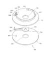
図1乃至図5を用いて実施例1について説明する。まず、図1、図2を用いて本実施例の光調節装置100の構成を説明する。図1は光調節装置100の分解図を示し、図2は光調節装置100の組立図を示す。図1に示す様に、光調節装置100は、第1の基板101と、第2の基板201と、光調節手段301とで構成される。
Embodiment 1 will be described with reference to FIGS. First, the configuration of the light adjusting
第1の基板101には、第1の開口102と、回転軸穴103と、駆動軸穴104とが形成され、駆動軸穴104の両端近傍には磁石501、502が対向するように配置される。また、第1の基板101上には、基板101上に接着固定された電極402と、電極402に固定された高分子アクチュエータ401と、高分子アクチュエータ401の先端に接着固定された連結部材403とが設けられている。第2の基板201には、第2の開口202と回転軸203とが形成されている。光調節手段301には、第1の開口102及び第2の開口202よりも小さい第3の開口302と駆動軸304と回転軸穴303とが形成されている。
The
回転軸203は、光調節手段301の回転軸穴303を介して第1の基板101の回転軸穴103に挿入される。図2に示すように、駆動軸304は、駆動軸穴104を介して連結部材403により高分子アクチュエータ401と連結される。
The rotating
次にアクチュエータ部分の詳細を図3に基づいて説明する。対向する両面に電極を形成した円弧形状の高分子アクチュエータ401は、円弧の基材となるイオン含有ポリマー411と、円弧の外側の面に設けられた第1電極412と、それに対向する面に設けられた第2電極413との3層構造となっている。
Next, details of the actuator portion will be described with reference to FIG. An arc-
ここで外部電圧源(図には示していない)から電圧を出力して第1電極412と第2電極413との間に電位差を与える。イオン含有ポリマー411の陽イオンは、カソード側に移動する。その結果イオン含有ポリマー411のカソード側が膨潤して、図3に示す点線のように円弧形状の曲率が変化して結果として弦長が変化する。このように外部電圧源の出力電圧によって高分子アクチュエータ401の弦長を所定範囲で変化させることができる。
Here, a voltage is output from an external voltage source (not shown), and a potential difference is applied between the
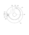
以下、各構成要素の詳細について説明する。図4及び図5は光調節装置の上面図を示しており、図4は高分子アクチュエータ401、磁石501、502の図示を省略した状態図である。
Details of each component will be described below. 4 and 5 are top views of the light adjusting device, and FIG. 4 is a state diagram in which the
図5に示すように第1の基板101に形成された回転軸穴103の径は回転軸203の径よりも僅かに大きく設定する。また、駆動軸穴104は、その幅が駆動軸304の径よりも僅かに大きく、磁石501、502の対向する方向に駆動軸304が回転軸203を中心に移動可能なように溝をなしている。
As shown in FIG. 5, the diameter of the
また、図1より、第2の基板201の第2の開口202の径は、第1の基板101の第1の開口102の径と同じ、もしくは僅かに大きく設定する。さらに、図4に示すように、光調節手段301は回転軸203を軸として回転が可能に構成されている。駆動軸304の移動により、光調節手段301を回転動作させる。これにより、第1の開口102と第3の開口302とで規定される開口径を切り換える。この結果、光調節装置の開口径を切り換える可変絞りとして機能する。また、連結部403は磁性体で形成されている。
From FIG. 1, the diameter of the second opening 202 of the
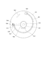
図5、図6を用いて本実施例の光調節装置の動作を説明する。図5、図6は光調節装置の上面図を示している。図5、図6に示すように、高分子アクチュエータ401は電極402に通電することで、円弧形状の曲率が変わり、その結果変位する。磁性体よりなる連結部材403が磁石501に突き当てられたとき、光調節手段301は、第3の開口302と第1の開口102とが重なる第1の静止位置に移動し、静止する。このとき、光調節装置の開口は、第3の開口302となる。
The operation of the light adjusting device of this embodiment will be described with reference to FIGS. 5 and 6 show top views of the light adjusting device. As shown in FIGS. 5 and 6, when the
これに対して、連結部材403が磁石502に突き当てられた時、光調節手段301は、第3の開口302が第1の開口102から完全に退避した第2の静止位置に移動し、静止する。このとき、光調節装置の開口は第1の開口102となる。
On the other hand, when the connecting
図5は光調節装置において光調節手段301が、第1の開口102と重なる第1の静止位置にあるときの状態図である。この状態の時、高分子アクチュエータ401に通電は行わず、光調節手段301は、磁性体よりなる連結部材403が磁石501の磁力によってその第1の静止位置に保持されている。高分子アクチュエータ401は、通電に応じてその曲率が変わり、変位する。
FIG. 5 is a state diagram when the light adjusting means 301 is in the first stationary position overlapping the
これに応じて、高分子アクチュエータ401に接続された連結部材403は、駆動軸穴104の溝に沿って駆動軸304を移動させ、光調節手段301が回転軸203を中心に回転する。そして、磁性体よりなる連結部材403は磁石502に突き当てられ、図6に示すように光調節手段301は第2の静止位置で静止する。この時、高分子アクチュエータ401への通電を止める。磁石502の磁力によって磁性体よりなる連結部材403は、第2の静止位置で保持される。
In response to this, the connecting
本実施例では、光調節手段301の初期位置を第1の静止位置にして説明したが、初期位置が第2の静止位置にあっても同様である。また、本実施例の構成要素を以下のように変更しても、上述と同様の効果を得ることができる。
In the present embodiment, the initial position of the
即ち、磁性体で構成される要素を連結部材403ではなく、駆動軸304としても同様の効果が得られる。さらに、駆動軸穴104の両端近傍に配置した磁石501、502を磁性体にし、駆動軸304、もしくは連結部材403を磁石で形成しても同様の効果が得られる。
That is, the same effect can be obtained when the element formed of a magnetic material is used as the
このように本実施例では、光調節手段301の切り換えにおいて、磁性体よりなる連結部材403、もしくは磁性体よりなる駆動軸304を磁石で保持することによって、光調節手段301を所定の位置で保持することが可能となる。したがって、高分子アクチュエータ401への通電は、光調節手段301を切り換える時だけになり、光調節手段301を所定の位置で保持する為に高分子アクチュエータ401に通電する必要がなくなる。これにより、無駄な消費電力を低減できると共に、高分子アクチュエータ401に常時通電することによって起こりうる変位量の低下も低減することが可能となる。
As described above, in this embodiment, when the light adjusting means 301 is switched, the light adjusting means 301 is held at a predetermined position by holding the connecting
なお、本実施形態に示した一対の磁石501、502は、連結部材403の移動を制御するストッパーとしての役割も持つ為、光調節手段301を所定の位置で静止させる働きも持ち合わせる。
Note that the pair of
次に図7及至図9を用いて本発明の実施例2について説明する。実施例1と同一の構成要素には、同一の付番をし、重複する説明を省略する。 Next, Embodiment 2 of the present invention will be described with reference to FIGS. The same constituent elements as those in the first embodiment are assigned the same reference numerals, and redundant description is omitted.
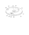
図7は、光調節装置の上面図、図8、図9はそれぞれ光調節手段301の位置、動作が見易いよう、光調節装置から第1の基板101の図示を省略した上面図である。図7に示すように、実施例2では、実施例1における磁石501、502は取り除かれている。そして、図8、図9に示すように第2の基板201上に磁石601、602が配置される。磁石601、602の厚さは等しく、光調節手段301の厚さよりも厚い。
FIG. 7 is a top view of the light adjusting device, and FIGS. 8 and 9 are top views in which the
図8に示すように、磁石601は光調節手段301が磁石601に突き当てられて第1の静止位置に静止するように配置される。磁石602は光調節手段301が磁石602に突き当てられて第2の静止位置に静止するように配置される。また、本実施例では光調節手段301は磁性体より形成される。
As shown in FIG. 8, the
図7乃至図9を用いて本実施例の光調節装置の動作を説明する。図8は光調節装置において光調節手段301が、第1の開口102と重なる第1の静止位置にあるときの状態図である。この状態の時、高分子アクチュエータ401に通電は行わず、磁性体よりなる光調節手段301が磁石601の磁力によって第1の静止位置に保持されている。高分子アクチュエータ401は、通電に応じてその曲率が変わり、変位する。
The operation of the light adjusting device of this embodiment will be described with reference to FIGS. FIG. 8 is a state diagram when the light adjusting means 301 is in the first stationary position overlapping the
これに応じて高分子アクチュエータ401に接続された連結部材403が駆動軸穴104の溝に沿って駆動軸304を移動させる。光調節手段301は、回転軸203を中心に回転する。そして、磁性体よりなる光調節手段301は磁石602に突き当てられ、図9に示すように第2の静止位置で静止する。このとき、静止に応じて高分子アクチュエータ401への通電を止める。磁性体よりなる光調節手段301は、磁石602の磁力によって第2の静止位置で保持される。
In response to this, the connecting
なお、磁石601、602の厚さは、光調節手段301よりも厚いため、第1の基板101と第2の基板201とのスペーサーとなり、光調節手段301が第1の基板101と第2の基板201とに挟まれ、動作しにくくなることはない。
Since the
本実施例においても、光調節手段301の初期位置を第1の静止位置にして説明したが、初期位置が第2の静止位置にあっても同様である。また、本実施例では光調節手段301が磁性体で形成されたが、磁石601、602が磁性体で、光調節手段301が磁石で形成されていても同様の効果が得られる。
Also in this embodiment, the initial position of the
本実施例は、実施例1の利点と同様、高分子アクチュエータ401に通電せずに光調節手段301を所定の位置で保持できる為、消費電力の発生を抑えると共に、常時通電することにより起こりうる高分子アクチュエータの変位量の低下も低減することが可能となる。
In the present embodiment, similar to the advantages of the first embodiment, the light adjusting means 301 can be held at a predetermined position without energizing the
本実施例では実施例1とは異なり、磁石601、602を第1の基板101と第2の基板201との間に配置している。そのため、磁石601、602が2つの基板間のスペーサーとしての機能を持ち、別途スペーサ―を配置する必要がなくなる。さらに、磁石を第1の基板101上に配置する必要がなくなるので、第1の基板101上のスペースを広く得ることが可能となり、アクチュエータ配置等、設計の自由度が増える。
In this embodiment, unlike the first embodiment, the
次に、図10を用いて本発明の実施例3について説明する。図10は、本実施例の光調節装置の斜視図である。各構成要素が見易いよう、第1の基板101と第2の基板201とに分解して示している。実施例1及び実施例2と同一の構成要素には、同一の付番をし、重複する説明を省略する。
Next, Embodiment 3 of the present invention will be described with reference to FIG. FIG. 10 is a perspective view of the light adjusting device of this embodiment. In order to make each component easy to see, the
本実施例では、第2の基板201の裏面に薄板状の磁石701を配置する。磁石701は図10に示すように、第1の基板101に形成された駆動軸穴104と対向する位置に接着固定される。また図には示さないが、駆動軸304が駆動軸穴104のいずれかの端部に移動した時に、光調節手段301は第1、及び第2の静止位置に移動する。また、本実施例では連結部材403は磁性体よりなる。なお、連結部材403は、常時磁石701の磁力の影響下にあり、高分子アクチュエータ401による連結部材403の駆動力は、磁石701の磁力より強く設定される。
In this embodiment, a thin plate-
図10は、光調節装置において光調節手段301が、第1の開口102と重なる第1の静止位置にあるときの状態図である。この状態の時、高分子アクチュエータ401に通電は行わない。第2の基板201の裏面に配置された磁石701の磁力によって磁性体よりなる連結部材403は第1の静止位置に保持されている。高分子アクチュエータ401は、通電に応じてその曲率が変わり、変位する。
FIG. 10 is a state diagram when the
これに応じて、高分子アクチュエータ401に接続された磁性体よりなる連結部材403は、磁石701の発する磁力より強い駆動力により、駆動軸穴104の溝に沿って駆動軸304を駆動軸穴104の一方の端部へ移動する。これにより、光調節手段301は、回転軸203を中心に回転する。そして、駆動軸304が駆動軸穴104の端部へ移動し、光調節手段301は第1の基板101に形成された第1の開口102から退避した第2の静止位置で静止する。このとき、静止に応じて高分子アクチュエータ401への通電を止める。磁性体よりなる連結部材403は、磁石701の磁力によって、高分子アクチュエータ401の復元力に抗して、第2の静止位置で保持される。
Accordingly, the connecting
本実施例においても実施例1及び実施例2と同様、光調節手段301の初期位置を第1の静止位置にして説明したが、初期位置が第2の静止位置にあっても同様である。また、本実施例では連結部材403を磁性体として説明したが、駆動軸304を磁性体で形成しても、同様の効果を得ることが出来る。さらに、磁石701を磁性体にし、連結部材403、もしくは駆動軸304を磁石で形成しても同様の効果を得ることが出来る。
In the present embodiment, as in the first and second embodiments, the initial position of the
本実施例の利点としては、実施例1及び実施例2の利点と同様、高分子アクチュエータ401に通電せずに光調節手段301を所定の位置で保持できる。このため、消費電力の発生を抑えると共に、常時通電することによる起こりうる高分子アクチュエータ401の変位量の低下も低減することが可能となる。
As an advantage of the present embodiment, similar to the advantages of the first embodiment and the second embodiment, the light adjusting means 301 can be held at a predetermined position without energizing the
また、本実施例では、実施例1及び実施例2とは異なり、磁石701を、他の構成要素を設けていない第2の基板201の裏面に配置している。このため、磁石701を接着固定することが比較的容易に可能となる。また、実施例2と同様、第1の基板101上のスペースを広く得ることが可能となり、アクチュエータ配置等、設計の自由度が増える。
In the present embodiment, unlike the first and second embodiments, the
次に、図11、図12を用いて本発明の実施例4に係る光調節装置について説明する。上記各実施例と同一の部分には同一の符号を付し、重複する説明は省略する。図11は、第1の基板101と第2の基板201を分解した状態を示しており、図12は構成を見易くする為、第1の基板101上に配置されたものは表示せず、横から見た状態を示している。
Next, a light adjusting apparatus according to Embodiment 4 of the present invention will be described with reference to FIGS. The same parts as those in the above-described embodiments are denoted by the same reference numerals, and redundant description is omitted. FIG. 11 shows a state in which the
以下、本実施例の光調節装置の構成を説明する。本実施例では、第2の基板201の裏面にコイルが巻かれた磁性体801を介して、磁石802が配置されている。コイルが巻かれた磁性体801と磁石802とは図11に示すように、第1の基板101に形成された駆動軸穴104に対向する位置に接着固定される。また図には詳しく示さないが、駆動軸304が駆動軸穴104のいずれかの端部に移動した時に、光調節手段301は第1及び第2の静止位置に移動する。また、本実施形態では連結部材403は磁性体よりなる。
Hereinafter, the configuration of the light adjusting device of this embodiment will be described. In this embodiment, a
図11は、光調節装置において光調節手段301が、第1の開口102と重なる第1の静止位置にあるときの状態図である。この状態の時、高分子アクチュエータ401に通電は行わない。磁性体よりなる連結部材403は、第2の基板201の裏面に配置された磁石802の磁力によって第1の静止位置に保持される。ここで磁性体801のコイルに、電流を流し、磁石802の磁力を打ち消す。コイルに流す電流の向きは、磁石802の磁力を打ち消す向きにあらかじめ設定しておく。
FIG. 11 is a state diagram when the
その状態で、高分子アクチュエータ401に通電することで、高分子アクチュエータ401の曲率が変わり、変位する。高分子アクチュエータ401に接続された磁性体よりなる連結部材403は、磁力が無い状態の中で、駆動軸穴104の溝に沿って駆動軸304を駆動軸穴104の一方の端部へ移動させる。光調節手段301は、回転軸203を中心に回転する。
In this state, when the
そして、駆動軸304が駆動軸穴104の端部へ移動し、光調節手段301は第1の基板101に形成された第1の開口102から退避した第2の静止位置で静止する。このとき、静止に応じて、高分子アクチュエータ401への通電を止める。また、磁性体801のコイルへの通電も止める。そうすることにより、磁性体よりなる連結部材403は、磁石802の磁力によって第2の静止位置で保持される。
Then, the
本実施例においても上記実施例1、2、3同様に、光調節手段301の初期位置を第1の静止位置にして説明したが、初期位置が第2の静止位置にあっても同様である。
In the present embodiment, as in the first, second, and third embodiments, the initial position of the
また、本実施例では連結部材403を磁性体として説明したが、駆動軸304を磁性体で形成しても同様の効果を得ることが出来る。さらに、コイルが巻かれた磁性体801を取り除き、磁石802に直接コイルを巻いても同様の効果を得ることが出来る。また、連結部材403若しくは駆動軸304を磁石で形成しても同様の効果を得ることが出来る。
In the present embodiment, the connecting
本実施例の利点としては実施例1、2、3の利点と同様、高分子アクチュエータ401及びコイルに通電せずに光調節手段301を所定の位置で保持できる。このため、消費電力の発生を抑えると共に常時通電することによる起こりうる高分子アクチュエータの変位量の低下も低減することが可能となる。
Similar to the advantages of the first, second, and third embodiments, the light adjusting means 301 can be held at a predetermined position without energizing the
また、本実施例によれば、実施例1、2とは異なり、コイルが巻かれた磁性体801と磁石802とを他の構成要素がない第2の基板201の裏面に配置することができる。そのため、磁性体801と磁石802とを比較的容易に接着固定することが可能となる。また、実施例2、3と同様、第1の基板101上のスペースを広く得ることが可能となり、アクチュエータ配置等、設計の自由度が増す。
Further, according to the present embodiment, unlike the first and second embodiments, the
また、本実施例では、高分子アクチュエータ401に通電し、連結部材403を移動させる際に、磁性体801のコイルに電流を流すことで磁石802の磁力を打ち消している。これにより、連結部材403の移動の際に磁力によって生じる摩擦がなくなり、実施例3よりさらにスムーズに移動することが可能となる。そして、光調節手段が第1または第2の静止位置に移動したとき、電流を止め、磁石による磁力で光調節手段をその位置に静止させることが可能となる。
Further, in this embodiment, when the
以上のように、本発明にかかる光調節装置は、撮像機能を有した携帯機器やマイクロビデオスコープ等の小型光学装置に有用であり、特に、高精度な位置制御を行う光調節装置に適している。 As described above, the light adjustment device according to the present invention is useful for a small optical device such as a portable device having an imaging function or a micro video scope, and particularly suitable for a light adjustment device that performs highly accurate position control. Yes.
101、201 基板
102、202、302 開口
103、303 回転軸穴
104 駆動軸穴
203 回転軸
301 光調節手段
304 駆動軸
401 高分子アクチュエータ
402、412、413 電極
403 連結部材
411 イオン含有ポリマー
501、502、601、602、701、802 磁石
801 磁性体
101, 201
Claims (7)
他の開口が形成された光調節手段と、
駆動源として、高分子アクチュエータとを具備し、
前記高分子アクチュエータに通電し、その形状を変化させることで、前記光調節手段を、前記基板に形成された開口の位置に重なる第1の静止位置と、前記基板に形成された前記開口の位置から退避した第2の静止位置とに相互に移動させて、前記基板に形成された前記開口と前記光調節手段に形成された前記他の開口とを切り換える光調節装置において、
さらに、磁石を備え、
前記光調節手段が前記第1の静止位置または前記第2の静止位置に移動した際、前記高分子アクチュエータへの通電を止め、前記磁石の磁力によって前記光調節手段を、前記第1または第2の静止位置に保持させることを特徴とする光調節装置。 A substrate with an opening formed thereon;
A light adjusting means in which another opening is formed;
As a drive source, comprising a polymer actuator,
By energizing the polymer actuator and changing its shape, the light adjusting means is moved to a first stationary position overlapping the position of the opening formed in the substrate, and the position of the opening formed in the substrate. In the light adjustment device that is moved to the second stationary position retracted from the substrate and switches between the opening formed in the substrate and the other opening formed in the light adjustment means,
In addition, with a magnet,
When the light adjusting means moves to the first stationary position or the second stationary position, the energization to the polymer actuator is stopped, and the light adjusting means is moved to the first or second by the magnetic force of the magnet. A light adjusting device characterized in that the light adjusting device is held at a stationary position.
前記駆動軸、及び前記高分子アクチュエータとの連結部材の可動範囲の両端部近傍には一対の磁石が配置され、
前記光調節手段が前記第1の静止位置、または前記第2の静止位置に移動した際、前記光調節手段の駆動軸、及び前記連結部材は前記一対の磁石のいずれかの磁力によって、その静止位置に保持されることを特徴とする請求項3に記載の光調節装置。 At least one of the drive shaft of the light adjusting means and the connecting member to the polymer actuator is formed of a magnetic material,
A pair of magnets are arranged in the vicinity of both ends of the movable range of the connecting member to the drive shaft and the polymer actuator,
When the light adjusting means is moved to the first stationary position or the second stationary position, the drive shaft of the light adjusting means and the connecting member are stationary by the magnetic force of the pair of magnets. The light adjusting device according to claim 3, wherein the light adjusting device is held in a position.
前記光調節手段が前記第1の静止位置または前記第2の静止位置に移動した際、前記磁性体で形成された光調節手段は前記一対の磁石のいずれかの磁力によってその静止位置に保持されることを特徴とする請求項3に記載の光調節装置。 The light adjusting means is formed of a magnetic material, and a pair of magnets is disposed in the vicinity of both ends of the movable range of the light adjusting means,
When the light adjusting means moves to the first stationary position or the second stationary position, the light adjusting means formed of the magnetic body is held at the stationary position by the magnetic force of one of the pair of magnets. The light adjusting device according to claim 3.
前記磁性体に対して、前記光調節装置の光軸方向に間隙を隔てて対向する薄板状の磁石が配置され、
前記高分子アクチュエータの変位によって前記光調節手段が変位し、
前記高分子アクチュエータの非通電時において、前記磁性体と前記薄板状磁石の磁力によって、前記高分子アクチュエータの復元力に抗して前記光調節手段の位置が保持されることを特徴とする請求項1に記載の光調節装置。 At least one of the light adjusting means, the drive shaft, and the connecting member of the polymer actuator is made of a magnetic material,
A thin plate-like magnet that is opposed to the magnetic body with a gap in the optical axis direction of the light adjusting device is disposed,
The light adjusting means is displaced by the displacement of the polymer actuator,
The position of the light adjusting means is held against the restoring force of the polymer actuator by the magnetic force of the magnetic body and the thin plate magnet when the polymer actuator is not energized. 2. The light adjusting device according to 1.
前記第1の磁性体に対して、前記光調節装置の光軸方向に間隙を隔てて対向する部位に、コイルが巻きつけられた第2の磁性体を介して薄板状の磁石が配置され、
前記光調節手段の変位時においては、前記コイルに前記薄板状の磁石の磁力を打ち消す向きの電流を流し、前記光調節手段の静止時においては、前記第1の磁性体と前記薄板状の磁石との磁力によって、前記高分子アクチュエータの復元力に抗して前記光調節手段の位置が保持されることを特徴とする請求項1に記載の光調節装置。
At least one of the light adjusting means, the drive shaft, and the connecting member of the polymer actuator is composed of a first magnetic body,
A thin plate-like magnet is disposed via a second magnetic body around which a coil is wound, at a portion facing the first magnetic body with a gap in the optical axis direction of the light adjusting device.
When the light adjusting means is displaced, a current is applied to the coil in a direction that cancels the magnetic force of the thin plate magnet. When the light adjusting means is stationary, the first magnetic body and the thin plate magnet are passed. The light adjusting device according to claim 1, wherein the position of the light adjusting means is held against the restoring force of the polymer actuator by the magnetic force.
Priority Applications (2)
| Application Number | Priority Date | Filing Date | Title |
|---|---|---|---|
| JP2007300467A JP2009128418A (en) | 2007-11-20 | 2007-11-20 | Light controlling apparatus |
| US12/272,431 US20090128880A1 (en) | 2007-11-20 | 2008-11-17 | Light controlling apparatus |
Applications Claiming Priority (1)
| Application Number | Priority Date | Filing Date | Title |
|---|---|---|---|
| JP2007300467A JP2009128418A (en) | 2007-11-20 | 2007-11-20 | Light controlling apparatus |
Publications (2)
| Publication Number | Publication Date |
|---|---|
| JP2009128418A true JP2009128418A (en) | 2009-06-11 |
| JP2009128418A5 JP2009128418A5 (en) | 2010-11-25 |
Family
ID=40641631
Family Applications (1)
| Application Number | Title | Priority Date | Filing Date |
|---|---|---|---|
| JP2007300467A Pending JP2009128418A (en) | 2007-11-20 | 2007-11-20 | Light controlling apparatus |
Country Status (2)
| Country | Link |
|---|---|
| US (1) | US20090128880A1 (en) |
| JP (1) | JP2009128418A (en) |
Families Citing this family (1)
| Publication number | Priority date | Publication date | Assignee | Title |
|---|---|---|---|---|
| US20220353390A1 (en) * | 2021-05-03 | 2022-11-03 | Tdk Taiwan Corp. | Optical component driving mechanism |
Citations (8)
| Publication number | Priority date | Publication date | Assignee | Title |
|---|---|---|---|---|
| JP2000314905A (en) * | 1999-04-30 | 2000-11-14 | Canon Inc | Diaphragm device |
| JP2001290195A (en) * | 2000-04-06 | 2001-10-19 | Nikon Corp | Lens barrel and camera having it |
| JP2006174629A (en) * | 2004-12-17 | 2006-06-29 | Canon Electronics Inc | Electromagnetic driving unit, light intensity controller, and optical instrument |
| JP2006284641A (en) * | 2005-03-31 | 2006-10-19 | Nidec Copal Corp | Blade drive unit for camera |
| JP2007034121A (en) * | 2005-07-29 | 2007-02-08 | Fujifilm Holdings Corp | Optical controller, optical control element, and photographing device |
| JP2007127709A (en) * | 2005-11-01 | 2007-05-24 | Sony Corp | Opening/closing device and photographing device using the same |
| JP2007127699A (en) * | 2005-11-01 | 2007-05-24 | Olympus Corp | Optical diaphragm unit |
| JP2007206362A (en) * | 2006-02-01 | 2007-08-16 | Komatsu Lite Seisakusho:Kk | Auto-focusing lens driving mechanism |
-
2007
- 2007-11-20 JP JP2007300467A patent/JP2009128418A/en active Pending
-
2008
- 2008-11-17 US US12/272,431 patent/US20090128880A1/en not_active Abandoned
Patent Citations (8)
| Publication number | Priority date | Publication date | Assignee | Title |
|---|---|---|---|---|
| JP2000314905A (en) * | 1999-04-30 | 2000-11-14 | Canon Inc | Diaphragm device |
| JP2001290195A (en) * | 2000-04-06 | 2001-10-19 | Nikon Corp | Lens barrel and camera having it |
| JP2006174629A (en) * | 2004-12-17 | 2006-06-29 | Canon Electronics Inc | Electromagnetic driving unit, light intensity controller, and optical instrument |
| JP2006284641A (en) * | 2005-03-31 | 2006-10-19 | Nidec Copal Corp | Blade drive unit for camera |
| JP2007034121A (en) * | 2005-07-29 | 2007-02-08 | Fujifilm Holdings Corp | Optical controller, optical control element, and photographing device |
| JP2007127709A (en) * | 2005-11-01 | 2007-05-24 | Sony Corp | Opening/closing device and photographing device using the same |
| JP2007127699A (en) * | 2005-11-01 | 2007-05-24 | Olympus Corp | Optical diaphragm unit |
| JP2007206362A (en) * | 2006-02-01 | 2007-08-16 | Komatsu Lite Seisakusho:Kk | Auto-focusing lens driving mechanism |
Also Published As
| Publication number | Publication date |
|---|---|
| US20090128880A1 (en) | 2009-05-21 |
Similar Documents
| Publication | Publication Date | Title |
|---|---|---|
| US7893965B2 (en) | Optical lens image stabilization systems | |
| JP2012124994A (en) | Driving device, lens barrel, and optical device having lens barrel | |
| JP2007127699A (en) | Optical diaphragm unit | |
| US7729069B2 (en) | Lens module and camera module having same | |
| CN100539230C (en) | The mechanism that comprises the ultrasound waveguide screw motor | |
| WO2010109825A1 (en) | Actuator, drive device, lens unit, image-capturing device | |
| JP2009128418A (en) | Light controlling apparatus | |
| KR20100096225A (en) | Piezoelectric movement of a lens | |
| JP2006191730A (en) | Drive unit and lens drive unit | |
| WO2020237450A1 (en) | Imaging device and information terminal | |
| JP2008122381A (en) | Stage using piezoelectric actuator and electronic device using stage | |
| KR20050093111A (en) | An apparatus for adjusting focal distance of camera lens using electro-magnetic force | |
| JP4623714B2 (en) | Camera module and portable terminal using the camera module | |
| JP5292954B2 (en) | Vibration actuator and lens barrel | |
| JP4484652B2 (en) | Camera module and portable terminal using the camera module | |
| TWI437795B (en) | Voice coil motor | |
| JP2009086433A (en) | Compact zoom lens barrel unit | |
| WO2010109826A1 (en) | Actuator, drive device, lens unit, image-capturing device, and operation method for actuator | |
| JP4623713B2 (en) | Camera module and portable terminal using the camera module | |
| KR100839996B1 (en) | Surface acoustic wave rotary motor and lens module driver using the rotary motor | |
| JP2010017037A (en) | Vibration actuator, lens unit, and image pickup apparatus | |
| JP2006098587A (en) | Camera module and personal digital assistant using same | |
| JP2009207254A (en) | Vibrating actuator, lens unit and imaging apparatus | |
| JP2019082505A (en) | Lens device and camera system | |
| JP2007121701A (en) | Optical device |
Legal Events
| Date | Code | Title | Description |
|---|---|---|---|
| A521 | Written amendment |
Free format text: JAPANESE INTERMEDIATE CODE: A523 Effective date: 20101008 |
|
| A621 | Written request for application examination |
Free format text: JAPANESE INTERMEDIATE CODE: A621 Effective date: 20101008 |
|
| A977 | Report on retrieval |
Free format text: JAPANESE INTERMEDIATE CODE: A971007 Effective date: 20120801 |
|
| A131 | Notification of reasons for refusal |
Free format text: JAPANESE INTERMEDIATE CODE: A131 Effective date: 20120808 |
|
| A02 | Decision of refusal |
Free format text: JAPANESE INTERMEDIATE CODE: A02 Effective date: 20121204 |