JP2009126530A - Band stopper for packing - Google Patents
Band stopper for packing Download PDFInfo
- Publication number
- JP2009126530A JP2009126530A JP2007301012A JP2007301012A JP2009126530A JP 2009126530 A JP2009126530 A JP 2009126530A JP 2007301012 A JP2007301012 A JP 2007301012A JP 2007301012 A JP2007301012 A JP 2007301012A JP 2009126530 A JP2009126530 A JP 2009126530A
- Authority
- JP
- Japan
- Prior art keywords
- hole
- band
- fastener
- frame
- frame body
- Prior art date
- Legal status (The legal status is an assumption and is not a legal conclusion. Google has not performed a legal analysis and makes no representation as to the accuracy of the status listed.)
- Pending
Links
Images


Landscapes
- Package Frames And Binding Bands (AREA)
Abstract
Description
本発明は梱包用バンド留め具に関する。 The present invention relates to a packing band fastener.
紙バンド等を用いて梱包物を結束するためのバンド留め具として、特許文献1に記載のものがある。この留め具は、合成樹脂製留め具の四辺形枠体に左右の長孔、中間部の長孔、右側の大きい孔、該枠体から右側の大きい孔の側傍に張り出されて片持ち支持されるI字形ストッパを有する。使用方法は、バンドの一端を中間部の長孔に通し、その先端を左側の長孔に通して締め付けておく。次いで、このバンドを梱包物に巻き付けてその他端を右側の大きい孔にループ状に差し込み、そのループ状空間内にI字形ストッパをその基部から折り曲げて差し込み、該他端を引っ張ってI字形ストッパに巻掛け係止し、梱包物の締め付け結束を完了する。
特許文献1に記載のバンド留め具には以下の問題点がある。
(1)留め具が四辺形枠体の外に張り出されて片持ち支持されるI字形ストッパを有し、構造複雑になる。また、留め具は、このI字形ストッパをその基部から折り曲げて使用するものであり、強度的に紙製にすることも困難がある。
The band fastener described in
(1) The fastener has an I-shaped stopper that is projected out of the quadrilateral frame and is cantilevered, which makes the structure complicated. Further, the fastener is used by bending the I-shaped stopper from its base, and it is difficult to make it stronger from paper.
(2)バンドの他端を留め具に係止する作業が、該他端を右側の大きい孔にループ状に差し込み、そのループ状を維持しながら、そのループ状空間内にI字形ストッパをその基部から折り曲げて差し込み、該他端を引っ張ってI字形ストッパに巻掛け係止するものになる。バンドの係止作業性が非常に悪い。 (2) The operation of locking the other end of the band to the fastener is to insert the other end into a large hole on the right side in a loop shape, and while maintaining the loop shape, place the I-shaped stopper in the loop-shaped space. It is bent from the base and inserted, and the other end is pulled and wound around an I-shaped stopper. The band workability is very poor.
(3)梱包物の締め付け結束によりバンドに作用する結束張力は、バンドが巻掛け係止されるI字形ストッパにより担持される。ところが、I字形ストッパは枠体に片持ち支持されるに過ぎず、バンドに作用する結束張力の担持能力は低く、留め具が同一材料からなるときに保証できるバンドの結束強度は低い。 (3) The binding tension acting on the band by tightening and binding the package is carried by an I-shaped stopper around which the band is wound and locked. However, the I-shaped stopper is only cantilevered by the frame, and the carrying capacity of the binding tension acting on the band is low, and the band binding strength that can be guaranteed when the fastener is made of the same material is low.
(4)留め具は梱包物の結束を完了したとき、梱包物の上面に配置される。このとき、留め具の梱包物の上面に対する最大高さは、枠体の板厚に、該枠体の上に折り曲げられたI字形ストッパの板厚を加えた高さになる。留め具の使用高さが徒らに大きくなる。 (4) The fastener is placed on the upper surface of the package when the packing of the package is completed. At this time, the maximum height of the fastener with respect to the upper surface of the package is a height obtained by adding the plate thickness of the I-shaped stopper bent on the frame to the plate thickness of the frame. The height of use of the fasteners is increased.
本発明の課題は、梱包用バンド留め具において、構造単純にし、バンドの挿通係止作業性を向上し、バンドの結束強度を高くし、使用高さを小さくすることにある。 An object of the present invention is to simplify the structure of a packing band fastener, improve the band insertion and locking workability, increase the band binding strength, and reduce the use height.
請求項1の発明は、枠体の中央部に設けられる通し孔と、枠体の一側部に設けられる第1の係止孔と、枠体の他側部に設けられる第2の係止孔を、枠体に並列配置し、枠体の第1の係止孔と通し孔とに挟まれる部分を第1の巻掛部とし、枠体の第2の係止孔と通し孔とに挟まれる部分を第2の巻掛部とする梱包用バンド留め具であって、バンドの両端のそれぞれが枠体の下面側から通し孔に挿通されて上面側に繰り出し可能にされ、バンドの通し孔から繰り出されて第1の巻掛部に巻掛られた一端が枠体の上面側から第1の係止孔に挿通されて下面側に繰り出し可能にされ、バンドの通し孔から繰り出されて第2の巻掛部に巻掛られた他端が枠体の上面側から第2の係止孔に挿通されて下面側に繰り出し可能にされるようにしたものである。 According to the first aspect of the present invention, there is provided a through hole provided at the center of the frame, a first locking hole provided at one side of the frame, and a second locking provided at the other side of the frame. The hole is arranged in parallel with the frame body, and the portion sandwiched between the first locking hole and the through hole of the frame body is used as the first winding portion, and the second locking hole and the through hole of the frame body are A packing band fastener having a sandwiched portion as a second winding portion, wherein both ends of the band are inserted into the through holes from the lower surface side of the frame body and can be extended to the upper surface side. One end that is drawn out from the hole and wound around the first winding portion is inserted into the first locking hole from the upper surface side of the frame body so that it can be drawn out to the lower surface side, and is drawn out from the through hole of the band. The other end wound around the second winding part is inserted into the second locking hole from the upper surface side of the frame so that it can be fed out to the lower surface side.
請求項2の発明は、請求項1の発明において更に、前記通し孔がバンドの両端挿通用として共用される唯1個の通し孔からなるようにしたものである。 According to a second aspect of the present invention, in the first aspect of the present invention, the through hole is composed of only one through hole shared for both ends of the band.
請求項3の発明は、請求項1又は2の発明において更に、前記枠体が厚紙からなるようにしたものである。 According to a third aspect of the present invention, in the first or second aspect of the present invention, the frame body is made of cardboard.
(請求項1)
(a)留め具が枠体の内部に通し孔と第1の係止孔と第2の係止孔を孔加工するだけの単純な構造からなる。留め具は枠体だけからなるものであり、強度的に紙製とすることも容易である。
(Claim 1)
(a) The fastener has a simple structure in which a through hole, a first locking hole, and a second locking hole are formed in the frame body. The fastener is composed only of a frame and can be easily made of paper in strength.
(b)バンドの一端を枠体の通し孔と第1の係止孔に順に挿通して留め具に係止し、バンドの他端を枠体の通し孔と第2の係止孔に順に挿通して留め具に係止するだけで、梱包物の締め付け結束を完了できる。バンドの係止作業性は非常に簡便である。 (b) One end of the band is inserted into the through hole of the frame body and the first locking hole in order and locked to the fastener, and the other end of the band is sequentially connected to the through hole of the frame body and the second locking hole. By simply inserting and locking to the fastener, the package can be tightened and bound. The band workability is very simple.
(c)梱包物の締め付け結束によりバンドの一端に作用する結束張力は、バンドの一端が巻掛け係止される第1の巻掛部により担持される。バンドの他端に作用する結束張力は、バンドの他端が巻掛け係止される第2の巻掛部により担持される。第1の巻掛部と第2の巻掛部は枠体に両持ち支持されるものであり、バンドに作用する結束張力の担持能力は高く、留め具が保証できるバンドの結束強度は高い。 (c) The binding tension acting on one end of the band due to the tight binding of the package is carried by the first winding portion around which one end of the band is wound and locked. The binding tension acting on the other end of the band is carried by the second winding portion where the other end of the band is wound and locked. The first winding portion and the second winding portion are both supported by the frame body, have a high carrying capacity of the binding tension acting on the band, and the binding strength of the band that the fastener can guarantee is high.
(d)留め具は梱包物の結束を完了したとき、梱包物の上面に配置される。このとき、留め具の梱包物の上面に対する最大高さは、枠体の板厚だけである。留め具の使用高さを小さくし、梱包物をコンパクトに結束できる。 (d) The fastener is placed on the top surface of the package when the packing of the package is completed. At this time, the maximum height of the fastener relative to the upper surface of the package is only the thickness of the frame. The use height of the fastener can be reduced, and the package can be bundled compactly.
(請求項2)
(e)留め具の通し孔は、バンドの一端挿通用の第1の挿し孔と他端挿通用の第2の挿し孔の2個の通し孔からなるものとすることもできるが、バンドの両端挿通用として共用される唯1個の通し孔からなるものにすることにより、留め具の構造を一層単純化できる。
(Claim 2)
(e) The through hole of the fastener may be composed of two through holes, a first insertion hole for inserting one end of the band and a second insertion hole for inserting the other end. The structure of the fastener can be further simplified by using only one through hole shared for both-end insertion.
(請求項3)
(f)留め具が単純な構造になるから、前述(a)の如くに紙製とすることができる。留め具の枠体を厚紙からなるものとすることにより、留め具を再資源化できる。
(Claim 3)
(f) Since the fastener has a simple structure, it can be made of paper as described above (a). By making the frame of the fasteners from cardboard, the fasteners can be recycled.
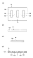
図1は留め具を示す模式図、図2は留め具によるバンドの締め付け結束方法を示す模式図、図3は留め具によるバンドの結束解除方法を示す模式図、図4は留め具によるバンドの締め付け結束方法の変形例を示す模式図、図5は留め具の変形例を示す模式図、図6は留め具の変形例を示す模式図である。 FIG. 1 is a schematic diagram showing a fastener, FIG. 2 is a schematic diagram showing a method of tightening and binding a band with the fastener, FIG. 3 is a schematic diagram showing a method of releasing the binding of the band with the fastener, and FIG. FIG. 5 is a schematic diagram showing a modified example of the fastener, FIG. 5 is a schematic diagram showing a modified example of the fastener, and FIG. 6 is a schematic diagram showing a modified example of the fastener.
図1に示す梱包用バンド留め具10は、合紙等の厚紙からなる矩形状の枠体10Aの中央部に設けられる長孔状の通し孔11と、枠体10Aの一側に設けられる長孔状の第1の係止孔12Aと、枠体10Aの他側に設けられる長孔状の第2の係止孔12Bを、互いに平行な3列をなすように枠体10Aに並列配置している。そして、留め具10は、枠体10Aの通し孔11と第1の係止孔12Aとに挟まれる部分を四角断面棒状の第1の巻掛部13Aとし、枠体10Aの通し孔11と第2の係止孔12Bとに挟まれる部分を四角断面棒状の第2の巻掛部13Bとする。留め具10は、厚紙素材をポンチとダイスにより打抜くプレス加工により、枠体10Aの外郭を打抜き、同時に通し孔11と係止孔12A、12Bを打抜いて製作できる。
The
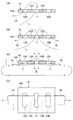
留め具10は、図2に示す如く、梱包物Pに巻き付けた平帯状の紙バンド1の両端1A、1Bのそれぞれが枠体10Aの下面側から通し孔11に挿通されて上面側に繰り出し可能とされ、バンド1の通し孔11から繰り出されて第1の巻掛部13Aに巻掛られた一端1Aが枠体10Aの上面側から第1の係止孔12Aに挿通されて下面側に繰り出し可能にされ、バンド1の通し孔11から繰り出されて第2の巻掛部13Bに巻掛られた他端1Bが枠体10Aの上面側から第2の係止孔12Bに挿通されて下面側に繰り出し可能にされる。このとき、留め具10は、バンド1の両端1A、1Bの挿通用として共用される唯1個の通し孔11を枠体10Aに備える。
As shown in FIG. 2, the
従って、留め具10の使用手順は以下の如くになる(図2)。
(1)梱包物Pに巻き付けられるバンド1の一端1Aを枠体10Aの下面側から通し孔11に挿通して上面側に繰り出し、この一端1Aを第1の巻掛部13Aに巻掛け、更に枠体10Aの上面側から第1の係止孔12Aに挿通して下面側に繰り出しておく(図2(A))。
Therefore, the procedure for using the
(1) One
(2)上述(1)のバンド1を梱包物Pに巻き付けてその他端1Bを枠体10Aの下面側から通し孔11に挿通して上面側に繰り出し、この他端1Bを第2の巻掛部13Bに巻掛け、更に枠体10Aの上面側から第2の係止孔12Bに挿通して下面側に繰り出す(図2(B))。
(2) The
(3)上述(2)のバンド1の他端1B(一端1Aでも可)を引っ張り、この他端1Bを枠体10Aの通し孔11、第2の巻掛部13B、第2の係止孔12Bから一層繰り出し、バンド1を張力Tで梱包物Pに引き締める。このとき、留め具10の枠体10Aはバンド1の両端1A、1Bを梱包物Pの上面との間に挟んで梱包物Pの上面に引き寄せ配置される。これにより、バンド1の通し孔11に挿通された一端1Aは、張力Tで第1の巻掛部13Aの上下面側角エッジa、bに強く押し当て係止されて巻掛けられ、かつ第1の係止孔12Aの下面側角エッジcに押し当て係止されて巻掛けられ、第1の巻掛部13Aにゆるみなく巻掛け係止保持される(図2(C)、(D))。また、バンド1の通し孔11に挿通された他端1Bも、張力Tで第2の巻掛部13Bの上下面側角エッジa、bに強く押し当て係止されて巻掛けられ、かつ第2の係止孔12Bの下面側角エッジcに押し当て係止されて巻掛けられ、第2の巻掛部13Bにゆるみなく巻掛け係止保持され、結果としてバンド1による梱包物Pの締め付け結束を強固に完了する(図2(C)、(D))。
(3) Pull the
梱包物Pに締め付けたバンド1の結束を解除するときには、図3に示す如く、留め具10を梱包物Pの上面に対して斜めに傾け、或いは上方に持ち上げることにより、バンド1の一端1Aと第1の巻掛部13Aの上下面側角エッジa、b、第1の係止孔12Aの下面側角エッジcとの押し当て係止状態を解き、かつバンド1の他端1Bと第2の巻掛部13Bの上下面側角エッジa、b、第2の係止孔12Bの下面側角エッジcとの押し当て係止状態を解く。これにより、バンド1の両端1A、1Bは第1の巻掛部13A、第2の巻掛部13Bとの図3(A)に示す巻掛け係止状態を解かれ、バンド1は図3(B)に示す如くにたるんで梱包物Pに対する締め付けを解除できる。
When releasing the binding of the
尚、上述(3)の後、上述(1)で第1の係止孔12Aから繰り出してあるバンド1の一端1Aを、図4に示す如く、枠体10Aの上面側に巻掛けて枠体10Aの上面側から第2の係止孔12Bに挿通して下面側に繰り出しても良い。これによれば、バンド1による梱包物Pの締め付け結束を一層強固に完了できる。
After the above (3), one
バンド1の帯幅を例えば15mm、帯厚を例えば0.8mmとするとき、留め具10の諸元は例えば以下の通りとする。枠体10Aの横長さ(各孔11、12A、12Bの並列方向を横とし、各孔11、12A、12Bの長手方向を縦とする)41mm、縦長さ28mm、孔11、12A、12Bの孔長さ16mm(長孔のストレート部11mm、両側アール部各2.5mm)、孔11、12A、12Bの孔幅5mm、巻掛部13A、13Bの幅8mm。
When the band width of the
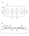
図1の留め具10は、通し孔11と係止孔12A、12Bの孔幅を互いに同一にした。但し、図5に示す如く、通し孔11の孔幅を係止孔12A、12Bの孔幅より広幅にしても良く、例えば通し孔11の孔幅8mm、係止孔12A、12Bの孔幅5mmとすることができる。
In the
図6の留め具10は、枠体10Aの中央部に設ける通し孔11を、バンド1の一端1A挿通用の第1の通し孔11Aと、他端1B挿通用の第2の通し孔11Bの2個からなるものにした(図6(A))。この留め具10にあっては、図6(B)に示す如く、バンド1の一端1Aが枠体10Aの下面側から第1の通し孔11Aに挿通されて上面側に繰り出し可能にされ、バンド1の通し孔11Aから繰り出されて第1の巻掛部13Aに巻掛られた一端1Aが枠体10Aの上面側から第1の係止孔12Aに挿通されて下面側に繰り出し可能にされる。また、バンド1の他端1Bが枠体10Aの下面側から第2の通し孔11Bに挿通されて上面側に繰り出し可能にされ、バンド1の通し孔11Bから繰り出されて第2の巻掛部13Bに巻掛けられた他端1Bが枠体10Aの上面側から第2の係止孔12Bに挿通されて下面側に繰り出し可能にされる。
The
留め具10によれば以下の作用効果を奏する。
(a)留め具10が枠体10Aの内部に通し孔11と第1の係止孔12Aと第2の係止孔12Bを孔加工するだけの単純な構造からなる。留め具10は枠体10Aだけからなるものであり、強度的に紙製とすることも容易である。
According to the
(a) The
(b)バンド1の一端1Aを枠体10Aの通し孔11と第1の係止孔12Aに順に挿通して留め具10に係止し、バンド1の他端1Bを枠体10Aの通し孔11と第2の係止孔12Bに順に挿通して留め具10に係止するだけで、梱包物Pの締め付け結束を完了できる。バンド1の係止作業性は非常に簡便である。
(b) One
(c)梱包物Pの締め付け結束によりバンド1の一端1Aに作用する結束張力Tは、バンド1の一端1Aが巻掛け係止される第1の巻掛部13Aにより担持される。バンド1の他端1Bに作用する結束張力Tは、バンド1の他端1Bが巻掛け係止される第2の巻掛部13Bにより担持される。第1の巻掛部13Aと第2の巻掛部13Bは枠体10Aに両持ち支持されるものであり、バンド1に作用する結束張力Tの担持能力は高く、留め具10が保証できるバンド1の結束強度は高い。
(c) The binding tension T acting on the one
(d)留め具10は梱包物Pの結束を完了したとき、梱包物Pの上面に配置される。このとき、留め具10の梱包物Pの上面に対する最大高さは、枠体10Aの板厚だけである。留め具10の使用高さを小さくし、梱包物Pをコンパクトに結束できる。
(d) The
(e)留め具10の通し孔11は、バンド1の一端1A挿通用の第1の通し孔11Aと他端1B挿通用の第2の通し孔11Bの2個の通し孔11A、11Bからなるものとすることもできるが、バンド1の両端挿通用として共用される唯1個の通し孔11からなるものにすることにより、留め具10の構造を一層単純化できる。
(e) The through-
(f)留め具10が単純な構造になるから、前述(a)の如くに紙製とすることができる。留め具10の枠体10Aを厚紙からなるものとすることにより、留め具10を再資源化できる。
(f) Since the
以上、本発明の実施例を図面により詳述したが、本発明の具体的な構成はこの実施例に限られるものではなく、本発明の要旨を逸脱しない範囲の設計の変更等があっても本発明に含まれる。例えば、本発明の留め具は紙製に限らず、合成樹脂等からなるものでも良い。バンドも紙製に限らず、合成樹脂等からなるものでも良い。 Although the embodiments of the present invention have been described in detail with reference to the drawings, the specific configuration of the present invention is not limited to these embodiments, and even if there is a design change or the like without departing from the gist of the present invention. It is included in the present invention. For example, the fastener of the present invention is not limited to paper but may be made of synthetic resin or the like. The band is not limited to paper and may be made of synthetic resin or the like.
1 バンド
1A 一端
1B 他端
10 留め具
10A 枠体
11、11A、11B 通し孔
12A 第1の係止孔
12B 第2の係止孔
13A 第1の巻掛部
13B 第2の巻掛部
P 梱包物
1
Claims (3)
枠体の第1の係止孔と通し孔とに挟まれる部分を第1の巻掛部とし、枠体の第2の係止孔と通し孔とに挟まれる部分を第2の巻掛部とする梱包用バンド留め具であって、
バンドの両端のそれぞれが枠体の下面側から通し孔に挿通されて上面側に繰り出し可能にされ、
バンドの通し孔から繰り出されて第1の巻掛部に巻掛られた一端が枠体の上面側から第1の係止孔に挿通されて下面側に繰り出し可能にされ、
バンドの通し孔から繰り出されて第2の巻掛部に巻掛られた他端が枠体の上面側から第2の係止孔に挿通されて下面側に繰り出し可能にされる梱包用バンド留め具。 A through hole provided in the center of the frame, a first locking hole provided on one side of the frame, and a second locking hole provided on the other side of the frame are arranged in parallel with the frame. Place and
A portion sandwiched between the first locking hole and the through hole of the frame is defined as a first winding portion, and a portion sandwiched between the second locking hole and the through hole of the frame is defined as a second winding portion. And a packing band fastener
Each end of the band is inserted into the through hole from the lower surface side of the frame body, and can be extended to the upper surface side.
One end which is drawn out from the through hole of the band and wound around the first winding part is inserted into the first locking hole from the upper surface side of the frame body and can be drawn out to the lower surface side.
Packing band clamp in which the other end, which is fed out from the through hole of the band and wound around the second winding part, is inserted into the second locking hole from the upper surface side of the frame body and can be fed out to the lower surface side. Ingredients.
Priority Applications (1)
| Application Number | Priority Date | Filing Date | Title |
|---|---|---|---|
| JP2007301012A JP2009126530A (en) | 2007-11-20 | 2007-11-20 | Band stopper for packing |
Applications Claiming Priority (1)
| Application Number | Priority Date | Filing Date | Title |
|---|---|---|---|
| JP2007301012A JP2009126530A (en) | 2007-11-20 | 2007-11-20 | Band stopper for packing |
Publications (2)
| Publication Number | Publication Date |
|---|---|
| JP2009126530A true JP2009126530A (en) | 2009-06-11 |
| JP2009126530A5 JP2009126530A5 (en) | 2010-02-04 |
Family
ID=40817848
Family Applications (1)
| Application Number | Title | Priority Date | Filing Date |
|---|---|---|---|
| JP2007301012A Pending JP2009126530A (en) | 2007-11-20 | 2007-11-20 | Band stopper for packing |
Country Status (1)
| Country | Link |
|---|---|
| JP (1) | JP2009126530A (en) |
Cited By (1)
| Publication number | Priority date | Publication date | Assignee | Title |
|---|---|---|---|---|
| JP2016108049A (en) * | 2014-12-02 | 2016-06-20 | 株式会社 ダイサン | Loading object restraint tool |
Citations (4)
| Publication number | Priority date | Publication date | Assignee | Title |
|---|---|---|---|---|
| JPS451439Y1 (en) * | 1967-07-27 | 1970-01-21 | ||
| JPS498704Y1 (en) * | 1969-08-30 | 1974-03-01 | ||
| JPS59199456A (en) * | 1983-04-23 | 1984-11-12 | 高野 稔啓 | Band clamping tool for packing and use thereof |
| JP2005041507A (en) * | 2003-07-24 | 2005-02-17 | Fasuko Boeki Kk | Tightening band |
-
2007
- 2007-11-20 JP JP2007301012A patent/JP2009126530A/en active Pending
Patent Citations (4)
| Publication number | Priority date | Publication date | Assignee | Title |
|---|---|---|---|---|
| JPS451439Y1 (en) * | 1967-07-27 | 1970-01-21 | ||
| JPS498704Y1 (en) * | 1969-08-30 | 1974-03-01 | ||
| JPS59199456A (en) * | 1983-04-23 | 1984-11-12 | 高野 稔啓 | Band clamping tool for packing and use thereof |
| JP2005041507A (en) * | 2003-07-24 | 2005-02-17 | Fasuko Boeki Kk | Tightening band |
Cited By (1)
| Publication number | Priority date | Publication date | Assignee | Title |
|---|---|---|---|---|
| JP2016108049A (en) * | 2014-12-02 | 2016-06-20 | 株式会社 ダイサン | Loading object restraint tool |
Similar Documents
| Publication | Publication Date | Title |
|---|---|---|
| JP2009126530A (en) | Band stopper for packing | |
| JP3655596B2 (en) | Shipping container | |
| JP3141859U (en) | Packing tool | |
| JP2013163548A (en) | Planar bundling band and connected body of the planar bundling band | |
| KR200384926Y1 (en) | Packaging band and connecting holder having connecting system with connecting hole | |
| JP2002179131A (en) | Elastic buckle with baggage packing handle | |
| TW202012269A (en) | Environment-friendly cable ties bundling capable of joining a used cable tie with another cable tie without producing excess cable ties, while being environment-friendly | |
| JP2006206175A (en) | Fastening band hardly allowing cargo to collapse | |
| JP2008018988A (en) | Load collapse preventing sheet and load fastening method using the same | |
| JPH08133331A (en) | Band tool for cross-tying | |
| JP2009214929A (en) | Reinforcing device | |
| US11673710B2 (en) | Securing apparatus for packaging and shipping | |
| CN219428762U (en) | Bundling structure for cylindrical materials | |
| US1420148A (en) | Strap and fastener | |
| JP2000168718A (en) | Fastening apparatus | |
| JPH082137Y2 (en) | Tie for strings | |
| KR200302543Y1 (en) | binding-tool for band | |
| JP2006143320A (en) | Binder | |
| KR20080003053U (en) | Cable tie for packing | |
| JP5142790B2 (en) | Tying aid | |
| TWM574589U (en) | Environmentally-friendly looping band | |
| JP2005212826A (en) | Belt tightening buckle | |
| JP2005042773A (en) | Band tightener | |
| JP2006241660A (en) | Tool for binding and fastening rope end | |
| JP2005083405A (en) | Tight binding tool |
Legal Events
| Date | Code | Title | Description |
|---|---|---|---|
| A521 | Written amendment |
Effective date: 20091211 Free format text: JAPANESE INTERMEDIATE CODE: A523 |
|
| A621 | Written request for application examination |
Effective date: 20091211 Free format text: JAPANESE INTERMEDIATE CODE: A621 |
|
| A977 | Report on retrieval |
Effective date: 20111216 Free format text: JAPANESE INTERMEDIATE CODE: A971007 |
|
| A131 | Notification of reasons for refusal |
Effective date: 20120105 Free format text: JAPANESE INTERMEDIATE CODE: A131 |
|
| A02 | Decision of refusal |
Effective date: 20120508 Free format text: JAPANESE INTERMEDIATE CODE: A02 |