JP2009110918A - Lighting device for high-voltage discharge lamp and light source device - Google Patents
Lighting device for high-voltage discharge lamp and light source device Download PDFInfo
- Publication number
- JP2009110918A JP2009110918A JP2008052785A JP2008052785A JP2009110918A JP 2009110918 A JP2009110918 A JP 2009110918A JP 2008052785 A JP2008052785 A JP 2008052785A JP 2008052785 A JP2008052785 A JP 2008052785A JP 2009110918 A JP2009110918 A JP 2009110918A
- Authority
- JP
- Japan
- Prior art keywords
- current
- discharge lamp
- pressure discharge
- electrode
- lighting device
- Prior art date
- Legal status (The legal status is an assumption and is not a legal conclusion. Google has not performed a legal analysis and makes no representation as to the accuracy of the status listed.)
- Pending
Links
Images


Abstract
Description
本発明は、第二反射鏡を備えた高圧放電灯の寿命を短くすることなく、安定した光出力が得られる高圧放電灯点灯装置、並びにその点灯装置を備えた光源装置に関する。 The present invention relates to a high pressure discharge lamp lighting device capable of obtaining a stable light output without shortening the life of a high pressure discharge lamp including a second reflecting mirror, and a light source device including the lighting device.
一般的に、プロジェクタ等の光源装置の光源として、発光管と発光管から放射された光を一定の方向に向ける主反射鏡とからなる放電灯が広く用いられている。このような放電灯において、発光管からの漏れ光を有効に利用して主反射鏡からの光の放出効率を上げるため、バルブ部を挟んで主反射鏡と対向する位置に第二反射鏡を配設することが行なわれている(例えば、特許文献1)。 Generally, as a light source of a light source device such as a projector, a discharge lamp including a light emitting tube and a main reflecting mirror that directs light emitted from the light emitting tube in a certain direction is widely used. In such a discharge lamp, in order to increase the light emission efficiency from the main reflecting mirror by effectively using the leakage light from the arc tube, the second reflecting mirror is placed at a position facing the main reflecting mirror across the bulb portion. Arrangement is performed (for example, patent document 1).
ただし、特許文献1のような手段を講じると、確かに光の放射効率を上げることはできるものの、第二反射鏡がバルブの発光部周辺を覆うように配設されるような場合には、第二反射鏡がバルブ部の放熱を阻害してしまう。その結果として、電極を含む第二反射鏡が配設されている側のバルブ部の温度上昇が顕著となり、電極の消耗、バルブの黒化、白濁化、バルブの変形を誘発してランプが短寿命となってしまう。
However, if measures such as
この問題を解決するための一つの手段として、第二反射鏡側の電極の熱容量を、主反射鏡側の電極の熱容量よりも大きくするという手段が開示されている(例えば、特許文献2)。
また別の手段として、第二反射鏡側の電極を支持する電極軸を主反射鏡側の電極軸より太く及び/又は長くする手段、第二反射鏡側の封止部を主反射鏡側の封止部より太くする手段、第二反射鏡側の封止部に該封止部の素材より熱伝導性が良い放熱材を被膜する手段、第二反射鏡により包囲されたバルブの発光部肉厚を主反射鏡側のバルブの発光部肉厚よりも大きくする手段、第二反射鏡側の電極の端部をバルブの内面に接触させる手段などが開示されている。また、一対の電極をそれぞれ支持する一対の電極軸を備え、一対の電極軸が、一対の電極と接続されている側の端部にそれぞれ熱伝導部を備え、一対の電極のうち第二反射鏡側の熱伝導部の熱容量を主反射鏡側の熱伝導部の熱容量より大きくする手段も開示されている。
As one means for solving this problem, a means is disclosed in which the heat capacity of the electrode on the second reflecting mirror side is made larger than the heat capacity of the electrode on the main reflecting mirror side (for example, Patent Document 2).
As another means, means for making the electrode axis supporting the electrode on the second reflector side thicker and / or longer than the electrode axis on the main reflector side, and sealing the second reflector side on the main reflector side Means thicker than the sealing part, means for coating the sealing part on the second reflecting mirror side with a heat radiation material having better thermal conductivity than the material of the sealing part, light emitting part of the bulb surrounded by the second reflecting mirror Means for making the thickness larger than the thickness of the light emitting portion of the bulb on the main reflector side, means for bringing the end of the electrode on the second reflector side into contact with the inner surface of the bulb, and the like are disclosed. In addition, a pair of electrode shafts that respectively support the pair of electrodes are provided, and the pair of electrode shafts are respectively provided with heat conducting portions at end portions connected to the pair of electrodes, and the second reflection of the pair of electrodes. Means for making the heat capacity of the heat conduction part on the mirror side larger than the heat capacity of the heat conduction part on the main reflector side is also disclosed.
これらの手段はいずれも、主反射鏡側よりも第二反射鏡側の熱容量を大きくする及び/又は放熱性を高めるというもので、これによりバルブの温度分布を均一化して第二反射鏡側のバルブ温度が上昇することにより誘発される問題を解決しようというものである。
しかしながら、特許文献2に記載された手段はすべて発光管、または発光管のバルブ部の仕様に関して、主反射鏡を取り付ける側と第二反射鏡を取り付ける側で違う仕様とするものである。すなわち発光管の材料、製造工程、さらには製造ジグまでが、発光管の一方ともう一方で違うものとしなければならない。この場合、材料調達の面では管理項目が増えることになり、製造工程においては工程の管理項目が増え、また工程が複雑になることが考えられる。また製造ジグもそれぞれ専用の物を準備しなければならず、コストも余分にかかることになる。
However, all the means described in
さらに、完成した発光管に反射鏡、及び第2反射鏡を取り付ける際に方向を誤って取り付けてしまうことも考えられる。もし、このランプが出荷されてしまうと非常に短寿命のランプとなってしまうし、たとえランプの製造検査工程で仕様の間違いを検出できたとしても、ランプを何回か点灯させてしまっていれば、ランプの電極には通常以上のダメージが与えられることになる。そのためそのランプは使用できなくなり、廃棄せざるを得なくなってしまうので、ランプ製造の歩留まりも悪化してしまう。 Furthermore, it is conceivable that the direction is mistakenly attached when the reflecting mirror and the second reflecting mirror are attached to the completed arc tube. If this lamp is shipped, it will be a very short-lived lamp, and even if a specification error is detected in the lamp manufacturing inspection process, the lamp will be lit several times. In this case, the lamp electrode is damaged more than usual. Therefore, the lamp cannot be used and must be discarded, so that the yield of lamp manufacturing is also deteriorated.
本発明の第1の側面は、対向配置された一対の発光用電極を有するバルブ部を備えた発光管及び発光管に付設される部材からなるとともに部材が一対の電極に対して非対称配置され、一対の電極に仮に正負対称交流電流を印加したならば一対の電極間の温度分布がその非対称配置に起因して不均一となる高圧放電灯を交流点灯する高圧放電灯点灯装置であって、一対の電極に正負非対称交流電流を供給するための交流電力供給手段を備え、その正負非対称交流電流について、正負対称交流電流を印加したならば低温側となる電極から高温側となる電極に向かって流れる電流(以下、「第1の電流」という)の電流時間積が、(正負対称交流電流を印加したならば)高温側となる電極から低温側となる電極に向かって流れる電流(以下、「第2の電流」という)の電流時間積よりも大きい高圧放電灯点灯装置である。 The first aspect of the present invention comprises a light emitting tube having a bulb portion having a pair of light emitting electrodes arranged opposite to each other and a member attached to the light emitting tube, and the members are disposed asymmetrically with respect to the pair of electrodes. A high-pressure discharge lamp lighting device for alternating-current lighting a high-pressure discharge lamp in which the temperature distribution between the pair of electrodes becomes non-uniform due to the asymmetrical arrangement if a positive and negative symmetrical alternating current is applied to the pair of electrodes. AC power supply means for supplying positive and negative asymmetrical alternating current to the electrodes of the positive and negative asymmetrical alternating current flows from the electrode on the low temperature side toward the electrode on the high temperature side when the positive and negative symmetrical alternating current is applied. The current-time product of the current (hereinafter referred to as “first current”) is a current (hereinafter referred to as “the first current”) flowing from the electrode on the high temperature side to the electrode on the low temperature side (if positive and negative symmetrical alternating current is applied). 2 A high pressure discharge lamp lighting device is greater than the current-time product of the current "hereinafter).
本発明の第2の側面は、対向配置された一対の発光用電極を有するバルブ部及びバルブ部の両端にバルブ部と一体に形成された電極に接続される導体を含むシール部を備えた発光管、シール部の一方に発光管からの光を一方向に反射させる主反射鏡、並びにシール部の他方に反射鏡よりも小さく、主反射鏡と対向する向きに配設された第二反射鏡からなる高圧放電灯を交流点灯するために、一対の電極に交流電流を供給するための交流電力供給手段を備えた高圧放電灯点灯装置において、交流電力供給手段によって供給される交流電流について、主反射鏡側の電極から第二反射鏡側の電極に向かって流れる電流(以下、「第1の電流」という)の電流時間積が、第二反射鏡側の電極から主反射鏡側の電極に向かって流れる電流(以下、「第2の電流」という)の電流時間積よりも大きい高圧放電灯点灯装置である。 A second aspect of the present invention is a light emitting device comprising a valve portion having a pair of light emitting electrodes arranged opposite to each other and a seal portion including conductors connected to electrodes formed integrally with the valve portion at both ends of the valve portion. A main reflecting mirror that reflects light from the arc tube in one direction on one of the tube and the seal portion, and a second reflecting mirror that is smaller than the reflecting mirror on the other side of the seal portion and disposed in a direction facing the main reflecting mirror In the high pressure discharge lamp lighting device having AC power supply means for supplying AC current to the pair of electrodes for AC lighting of the high pressure discharge lamp consisting of: The current-time product of the current flowing from the reflecting mirror side electrode toward the second reflecting mirror side electrode (hereinafter referred to as “first current”) is changed from the second reflecting mirror side electrode to the main reflecting mirror side electrode. Current flowing in the direction (hereinafter referred to as “second A high pressure discharge lamp lighting device is greater than the current-time product of the current "hereinafter).
ここで、上記第1及び第2の側面において、一対の電極が各電極専用の熱容量の異なる非対称電極からなり、その非対称電極に仮に正負対称交流電流を印加したならば非対称電極間の温度分布が各電極の熱容量の差に起因して不均一となる場合も想定できる。 Here, in the first and second aspects, the pair of electrodes are asymmetric electrodes having different heat capacities dedicated to each electrode, and if a positive / negative symmetric alternating current is applied to the asymmetric electrode, the temperature distribution between the asymmetric electrodes is The case where it becomes non-uniform | heterogenous due to the difference in the heat capacity of each electrode can also be assumed.
上記第1又は第2の側面において、正負非対称交流電流を矩形波として、第1の電流の波高値が第2の電流の波高値よりも高くなるようにした。
また、正負非対称交流電流を矩形波として、第1の電流の時間幅が第2の電流の時間幅よりも長くなるようにした。
またさらに、正負非対称交流電流を矩形波として、第1の電流の波高値が第2の電流の波高値よりも高く、かつ、第1の電流の時間幅が第2の電流の時間幅よりも長くなるようにした。
In the first or second aspect, the positive / negative asymmetrical alternating current is a rectangular wave so that the peak value of the first current is higher than the peak value of the second current.
Further, the positive / negative asymmetrical alternating current is a rectangular wave so that the time width of the first current is longer than the time width of the second current.
Furthermore, the positive / negative asymmetrical alternating current is a rectangular wave, the peak value of the first current is higher than the peak value of the second current, and the time width of the first current is larger than the time width of the second current. I made it longer.
また、上記第1又は第2の側面において、正負非対称交流電流を半サイクル内で電流値が所定の傾斜で増加する三角波として、第1の電流の傾斜が第2の電流の傾斜よりも小さくなるようにした。 In the first or second aspect, the positive and negative asymmetrical alternating current is a triangular wave whose current value increases at a predetermined slope within a half cycle, and the slope of the first current is smaller than the slope of the second current. I did it.
また、上記第1又は第2の側面において、第1の電流をI1、第2の電流をI2とし、点灯中のランプ電圧VA、VB(VA<VB)における電流I1及びI2のそれぞれの電流時間積をIt1A、It2A、It1B、It2Bとした場合、It1B/It2B<It1A/It2Aを満たす構成とした。 In the first or second aspect, the first current is I1, the second current is I2, and the currents I1 and I2 at the lamp voltages V A and V B (V A <V B ) are turned on. When each current-time product is It1 A , It2 A , It1 B , It2 B , the structure satisfying It1 B / It2 B <It1 A / It2 A is satisfied.
また、上記第1又は第2の側面において、正負非対称交流電流を間欠的に正負対称交流電流に挿入する構成としてもよい。 In the first or second aspect, a positive / negative asymmetrical alternating current may be intermittently inserted into the positive / negative symmetrical alternating current.
本発明の第3の側面は、上記第1又は第2の側面の高圧放電灯点灯装置、高圧放電灯並びに高圧放電灯点灯装置及び高圧放電灯を収容する筐体からなる光源装置である。 A third aspect of the present invention is a light source device comprising a high pressure discharge lamp lighting device, a high pressure discharge lamp, a high pressure discharge lamp lighting device and a high pressure discharge lamp according to the first or second aspect.
本発明によると、主反射鏡側の電極から第二反射鏡側の電極に向かって流れるランプ電流の実効値を、反対に第二反射鏡側の電極から主反射鏡側の電極に向かって流れるランプ電流の実効値よりも大きくなるように構成したので、第二反射鏡側の電極に衝突する電子の数が、主反射鏡側の電極に衝突する電子の数よりも少なくなる。そのため、主反射鏡側の電極と比較して第二反射鏡側の電極温度上昇が小さくなり、電極からの熱伝導、及び熱放射によるバルブ部の温度上昇も小さくなる。その結果、第二反射鏡によりバルブの放熱が阻害されたとしても、電極を含む第二反射鏡が配設されている側のバルブ部の温度上昇が顕著となることが避けられ、バルブの温度分布を均一化することができ、電極の消耗、バルブの黒化、白濁化、バルブの変形に伴うランプの短寿命化を防ぐことができる。 According to the present invention, the effective value of the lamp current flowing from the electrode on the main reflecting mirror side to the electrode on the second reflecting mirror side flows in the opposite direction from the electrode on the second reflecting mirror side to the electrode on the main reflecting mirror side. Since it is configured to be larger than the effective value of the lamp current, the number of electrons colliding with the electrode on the second reflecting mirror side becomes smaller than the number of electrons colliding with the electrode on the main reflecting mirror side. Therefore, the electrode temperature rise on the second reflector side is smaller than the electrode on the main reflector side, and the temperature rise of the bulb portion due to heat conduction and heat radiation from the electrode is also reduced. As a result, even if the heat radiation of the bulb is obstructed by the second reflecting mirror, it is avoided that the temperature rise of the bulb portion on the side where the second reflecting mirror including the electrode is disposed becomes significant, and the temperature of the bulb The distribution can be made uniform, and the life of the lamp can be prevented from being shortened due to electrode wear, blackening of the bulb, white turbidity, and bulb deformation.
また、本発明において点灯させる高圧放電灯は、発光管のバルブ部の仕様に関して、主反射鏡を取り付ける側と第二反射鏡を取り付ける側を同じ仕様とするものであるため、材料調達、製造工程における管理項目を増やす必要がなく、工程も簡素化できる。また製造ジグもそれぞれ専用の物を準備する必要はない。さらに、完成した発光管に主反射鏡、及び第二反射鏡を取り付ける際に、取り付け方向を指定しなくてもよい仕様とすることも可能であり、ランプ製造の歩留まりも悪化させることなく、ランプのコストダウンにも貢献する。 Further, the high-pressure discharge lamp to be lit in the present invention has the same specifications on the side where the main reflecting mirror is attached and the side where the second reflecting mirror is attached with respect to the specification of the bulb portion of the arc tube. There is no need to increase the number of management items, and the process can be simplified. Also, there is no need to prepare a dedicated jig for each production jig. Furthermore, when the main reflector and the second reflector are attached to the completed arc tube, it is possible to make the specification that does not require designation of the attachment direction, and the lamp manufacturing yield is not deteriorated. Contributes to cost reduction.
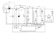
図1は本発明の回路構成図である。図1について以下に説明する。本発明の高圧放電灯点灯装置は、全波整流回路10、全波整流回路10の直流電圧をPWM(パルス幅変調)制御回路により所定のランプ電力又はランプ電流に制御する降圧チョッパ回路20、降圧チョッパ回路20の直流出力電圧を交流矩形波電流に変換してランプ60に印加するためのフルブリッジ回路40、ランプ始動時に高圧パルス電圧をランプに印加するためのイグナイタ回路50、並びに降圧チョッパ回路20及びフルブリッジ回路40を制御するための制御回路30で構成されている。なお、図面を見やすくするために整流回路10として全波整流・コンデンサインプット型の回路を示しているが、必要に応じて昇圧回路(力率改善回路)等も含むものとする。
FIG. 1 is a circuit configuration diagram of the present invention. 1 will be described below. The high pressure discharge lamp lighting device of the present invention includes a full-
降圧チョッパ回路20はPWM制御回路34によってPWM制御されるトランジスタ21、ダイオード22、チョークコイル23、及び平滑コンデンサ24で構成され、全波整流回路10から供給される直流電圧を所定のランプ電力又はランプ電流に変換するように制御される。フルブリッジ回路40はブリッジ制御回路45によってトランジスタ41及び44の組とトランジスタ42及び43の組とが所定の周波数で交互にオン/オフするように制御される。これにより、ランプ60に(基本的には矩形波の)交流電流が印加される。ランプ60には定格電力50〜400W程度のものを想定している。なお、上記の所定のランプ電力又はランプ電流の値及び所定の周波数は制御回路30内の中央制御部35によって決定される。また、定ランプ電流制御には抵抗33による検出ランプ電流を、定ランプ電力制御には抵抗31及び32による検出ランプ電圧と検出ランプ電流の乗算値を中央制御部35内において必要に応じて使用することができる。
The step-down
次に、本発明の実施形態について従来例と比較し説明する。
従来例を再度説明しておくと、従来例では図2で示す高圧放電灯に図4で示す矩形波のランプ電流ILを流し、前記高圧放電灯を点灯させている。この時ランプ電流ILの実効値(電流時間積)については、図4のように主反射鏡70側の電極から他方の電極に向かって流れるランプ電流I1と逆方向に流れるランプ電流I2において同じ値となっている。
Next, an embodiment of the present invention will be described in comparison with a conventional example.
Describing the conventional example again, in the conventional example, a rectangular wave lamp current IL shown in FIG. 4 is passed through the high pressure discharge lamp shown in FIG. 2 to light the high pressure discharge lamp. At this time, the effective value (current-time product) of the lamp current IL is the same in the lamp current I2 flowing in the opposite direction to the lamp current I1 flowing from the electrode on the
ここでランプが図3に示すような第二反射鏡80を有する高圧放電灯の場合、図4で示す矩形波のランプ電流によりランプを点灯すると、第二反射鏡80による保温効果、放熱抑制により主反射鏡70側のバルブ部より第二反射鏡80側のバルブ部の温度の方が上昇することとなる。
Here, in the case of a high pressure discharge lamp having a second reflecting
ランプの点灯時間が初期のものに関しては、図9に示す通り主反射鏡70側の電極91と第二反射鏡80側の電極92ともにその電極先端に突起ができているが、バルブ部の温度分布が不均一であるため、高圧放電灯の累積点灯時間が長くなると第二反射鏡80側の電極92の損耗が著しくなり、図10に示すように電極先端の突起が消滅したり、図11に示すように電極先端に細かい複数の突起が現れて荒れた状態となったりする。
As shown in FIG. 9, the
この電極先端の突起が消滅したり、電極先端が荒れた状態となったりする過程で電極92から飛散したタングステンは、バルブの内面に付着することとなり、この付着したタングステンによる保温効果により第二反射鏡80側のバルブ部の温度上昇は更に著しいものとなる悪循環を招いてしまう。結果としてランプの短寿命につながるバルブの黒化、白濁化、バルブの変形を誘発していた。
Tungsten scattered from the
これに対し本発明の実施形態では、第二反射鏡80を備えた図3で示す高圧放電灯に対し、主反射鏡70側の電極91から第二反射鏡80側の電極92に向かって流れるランプ電流I1の電流時間積It1を、反対に第二反射鏡80側の電極92から主反射鏡70側の電極91に向かって流れるランプ電流I2の電流時間積It2よりも大きくなるようにランプ電流を制御する。なお、高圧放電灯点灯装置と高圧放電灯を接続する際に、高圧放電灯点灯装置の2本の出力線と電極91及び92とが予め決められた極性で接続されるものとする。
In contrast, in the embodiment of the present invention, the high-pressure discharge lamp shown in FIG. 3 provided with the second reflecting
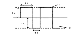
<ランプ電流制御方法1>
具体的には、図5で示すように、主反射鏡70側の電極91から第二反射鏡80側の電極92に向かって流れるランプ電流I1の波高値を、第二反射鏡80側の電極92から主反射鏡70側の電極91に向かって流れるランプ電流I2の波高値よりも高くすることで、電流時間積It1を電流時間積It2よりも大きくすることができる。
<Lamp
Specifically, as shown in FIG. 5, the peak value of the lamp current I1 flowing from the
<ランプ電流制御方法2>
また、図6で示すように、主反射鏡70側の電極91から第二反射鏡80側の電極92に向かって流れるランプ電流I1の時間幅T1を、第二反射鏡80側の電極92から主反射鏡70側の電極91に向かって流れるランプ電流I2の時間幅T2よりも広くする(T1>T2)ことでも、電流時間積It1を電流時間積It2よりも大きくすることができる。
<Lamp
In addition, as shown in FIG. 6, the time width T1 of the lamp current I1 flowing from the
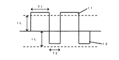
<ランプ電流制御方法3>
また、図7で示すように、上記ランプ電流制御方法1とランプ電流制御方法2を組み合わせてもよい。即ち、ランプ電流I1の波高値をランプ電流I2の波高値よりも大きくし、かつ、ランプ電流I1の時間幅をランプ電流I2の時間幅よりも広くし、これにより、電流時間積It1を電流時間積It2よりもさらに大きくすることができる。
<Lamp
Further, as shown in FIG. 7, the lamp
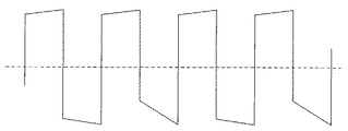
<ランプ電流制御方法4>
また、図8で示すように、上記ランプ電流制御方法1〜3に示した方法を連続的に実施するのではなく、間欠的に実施することとしてもよい。
<Lamp current control method 4>
Moreover, as shown in FIG. 8, it is good also as not performing continuously the method shown to the said lamp current control methods 1-3 but implementing intermittently.
<ランプ電流制御方法5>
また、図13に示すような、半サイクルにおいて電流値が増加するいわゆる三角波をベースとしてランプ電流を形成してもよい。この三角波は一般に電極上のアークの起点となる突起を形成・維持するのに好適な波形とされており、フリッカ防止対策として高圧放電灯点灯装置によく採用されるランプ電流波形である。
図15において、半サイクルの開始時電流をImin、終了時電流をImaxとした場合、主反射鏡70側の電極91から第二反射鏡80側の電極92に向かって流れるランプ電流I1のピーク値(Imax)と、第二反射鏡80側の電極92から主反射鏡70側の電極91に向かって流れるランプ電流I2のピーク値(Imax)を同程度にしつつも、I2の電流値増加の傾斜(Imax−Imin)がI1の傾斜よりも大きくなるようにした。
<Lamp current control method 5>
Alternatively, the lamp current may be formed based on a so-called triangular wave whose current value increases in a half cycle as shown in FIG. This triangular wave is generally a waveform suitable for forming and maintaining a projection that is the starting point of an arc on the electrode, and is a lamp current waveform that is often employed in high pressure discharge lamp lighting devices as a flicker prevention measure.
In FIG. 15, when the half-cycle start current is Imin and the end current is Imax, the peak value of the lamp current I1 flowing from the
<ランプ電流制御方法6>
また、図16で示すように、上記ランプ電流制御方法5に示した方法を連続的に実施するのではなく、間欠的に実施することとしてもよい。
<Lamp
Further, as shown in FIG. 16, the method shown in the lamp current control method 5 may be executed intermittently instead of continuously.
ランプ電流制御方法5又は6によると、降圧チョッパ回路20の出力ピーク電流を増やす必要がないので降圧チョッパ回路20を低損失に保つことができ、しかも、フルブリッジ回路40の駆動周波数を一定とすることができるのでブリッジ制御回路45の制御構成を簡素化することができ、これにより回路全体を高効率・低コストにすることができ好適である。
According to the lamp
上記ランプ電流制御方法1〜6により、主反射鏡70側の電極91から第二反射鏡80側の電極92に向かって流れるランプ電流I1の電流時間積を、第二反射鏡80側の電極92から主反射鏡70側の電極91に向かって流れるランプ電流I2の電流時間積よりも大きくすることができ、前記高圧放電灯のバルブ部温度分布を均一化することができる。
By the lamp
上記ランプ電流制御方法1〜6をまとめると、主反射鏡70側の電極91から第二反射鏡80側の電極92に向かって流れるランプ電流I1の電流時間積It1を、第二反射鏡80側の電極92から主反射鏡70側の電極91に向かって流れるランプ電流I2の電流時間積It2よりも大きくすることができれば、本発明の概念はどのようなランプ電流波形についても適用できる。
即ち、図17に示すように、どのような波形であっても図中の面積A(It1に相当)が面積B(It2に相当)よりも大きくなるようにすればよい。
When the lamp
That is, as shown in FIG. 17, the area A (corresponding to It1) in the figure may be larger than the area B (corresponding to It2) in any waveform.
また、上記ランプ電流制御方法1〜6において、「実効値I1rms>実効値I2rms」の傾向の強さ(即ち、偏り)を電極表面の状態に応じて変化させるようにしてもよい。なお、以降の説明において、「実効値I1rms>実効値I2rms」の傾向の強さ(即ち、偏り)を、α=I1rms/I2rms(但し、α>1)で表すものとする。
例えば、電極91上の突起がより成長し、電極92の表面の突起が溶解してしまっているような場合は、電極91側の温度が低く電極92側の温度が高い温度分布状態(以下、「状態A」という)にあるので、偏りαを増加させることが望ましい。
また逆に、電極91の表面の突起が溶解し、電極92上の突起が多少成長しているような場合は、電極91側の温度が高く電極92側の温度が低い温度分布状態(以下、「状態B」という)にあるので、偏りαを減少させることが望ましい。
In the lamp
For example, when the protrusion on the
Conversely, when the protrusions on the surface of the
なお、上記において「実効値I1rms」及び「実効値I2rms」をそれぞれ「電流時間積It1」及び「電流時間積It2」に置き換えても同様の作用効果を達成できることは言うまでもない。 Needless to say, the same effect can be achieved by replacing “effective value I1 rms ” and “effective value I2 rms ” with “current time product It1” and “current time product It2”, respectively.
より具体的には、状態Aの場合は電極間距離が短くなるのでランプ電圧が下がり、状態Bの場合は電極間距離が長くなるのでランプ電圧は上がる。従って、ランプ電圧が低ければ低いほど、即ち、状態Aの度合いが強まるほど、偏りαを増加させるのが好ましい。
従って、中央制御部35において、検出されるランプ電圧をVA、VB(VA<VB)として、それぞれのランプ電流の実効値をI1A、I2A、I1B、I2Bとした場合に、I1B/I2B<I1A/I2Aとなるようにすればよい。言い換えると、ランプ電圧の増加に対して、偏りαが単調減少するようにすればよい。
More specifically, in the case of state A, the lamp voltage decreases because the distance between the electrodes becomes short, and in the case of state B, the lamp voltage increases because the distance between the electrodes becomes long. Therefore, it is preferable to increase the bias α as the lamp voltage is lower, that is, as the degree of the state A is increased.
Accordingly, in the
なお、上記においても、実効値「I1A」、「I2A」、「I1B」及び「I2B」を、それぞれ電流時間積「It1A」、「It2A」、「It1B」及び「It2B」に置き換えても同様の作用効果を達成できることは言うまでもない。 Also in the above, the effective values “I1 A ”, “I2 A ”, “I1 B ”, and “I2 B ” are represented by current-time products “It1 A ”, “It2 A ”, “It1 B ”, and “It2”, respectively. It goes without saying that the same effect can be achieved even if it is replaced with “ B ”.
ここで、高圧放電灯のバルブ部温度分布を均一化するためのランプ電流I1の実効値等によって決まる電流時間積と、ランプ電流I2の実効値等によって決まる電流時間積の差異については実験的に求めることが望ましい。なぜなら、図3に示す第二反射鏡80を有する高圧放電灯を従来例のランプ電流により点灯させる場合、主反射鏡70側のバルブ部と第二反射鏡80側のバルブ部の温度分布の不均一度合いを決定するパラメータは多数あり、本発明を用いたとしても、バルブ部の温度分布を均一化するためのランプ電流I1の電流時間積とランプ電流I2の電流時間積の差を一義的に決定することは困難であるからである。
Here, the difference between the current-time product determined by the effective value of the lamp current I1 for equalizing the bulb temperature distribution of the high-pressure discharge lamp and the current-time product determined by the effective value of the lamp current I2 is experimentally determined. Desirable. This is because when the high-pressure discharge lamp having the second reflecting
それらパラメータとは、バルブに入力する電力、バルブの大きさ、形状、または主反射鏡70、及び第二反射鏡80の大きさ、形状、配設位置、またはランプの空冷条件など多岐に亘るため、実際にバルブ部の温度を測定しながらバルブ部の温度分布が均一となるような電流時間積の差を決定すればよい。
These parameters vary widely, such as the power input to the bulb, the bulb size, shape, or the size, shape, location, or lamp air cooling conditions of the
<設計例1>
上記を考慮した上で、発明者らは本発明の最も好適な実施例として以下のような高圧放電灯点灯装置を設計した。なお、使用ランプの定格電力は170Wである。いずれの設計例を用いた場合でも、従来の点灯を行った場合よりも短寿命ランプの発生が減ることが確認された。
ランプ電圧が70Vのランプを100Hzの矩形波電流で点灯させ、定格ランプ電流の実効値が2.43Aに対し、主反射鏡側の電極から第二反射鏡側の電極に向かって流れるランプ電流I1の波高値を10%増加させて2.67Aとして、第二反射鏡側の電極から主反射鏡側の電極に向かって流れるランプ電流I2の波高値を10%減少させて2.31Aとした。すなわち、実効値I1rmsを2.67Aとし、実効値I2rmsを2.31Aとした(この場合、電流時間積It1:It2も同様に2.67:2.31である)。
<Design example 1>
In consideration of the above, the inventors designed the following high pressure discharge lamp lighting device as the most preferred embodiment of the present invention. The rated power of the lamp used is 170W. In any design example, it was confirmed that the generation of short-life lamps was reduced as compared with the case of conventional lighting.
A lamp having a lamp voltage of 70 V is lit with a rectangular wave current of 100 Hz, and the effective value of the rated lamp current is 2.43 A, and the lamp current I1 that flows from the main reflector side electrode toward the second reflector side electrode. Was increased by 10% to 2.67A, and the peak value of the lamp current I2 flowing from the second reflector side electrode toward the main reflector side electrode was reduced by 10% to 2.31A. That is, the effective value I1 rms was set to 2.67A, and the effective value I2 rms was set to 2.31A (in this case, the current-time product It1: It2 is also 2.67: 2.31).
<設計例2>
設計例1と同様のランプにおいて、ランプを100Hzの矩形波電流で点灯させ、定格ランプ電流の実効値が2.43Aに対し、主反射鏡側の電極から第二反射鏡側の電極に向かって流れるランプ電流の波高値を2.43Aのままその時間幅を10%増加させて5.5m秒として、第二反射鏡側の電極から主反射鏡側の電極に向かって流れるランプ電流の波高値も2.43Aのままその時間幅を10%減少させて4.5m秒とした。すなわち、It1:It2=1.1:0.9とした。
<Design example 2>
In the same lamp as in Design Example 1, the lamp is lit with a rectangular wave current of 100 Hz, and the effective value of the rated lamp current is 2.43 A, from the electrode on the main reflector side toward the electrode on the second reflector side. The peak value of the lamp current that flows from the electrode on the second reflector side to the electrode on the main reflector side is increased to 5.5 milliseconds by increasing the time width by 10% while maintaining the peak value of the flowing lamp current at 2.43 A. However, the time width was reduced by 10% to be 4.5 msec. That is, It1: It2 = 1.1: 0.9.
<アプリケーション>
上記実施例では、ランプ寿命を向上した高圧放電灯点灯装置を示したが、それを用いたアプリケーションとしての光源装置を図12に示す。
図12において、100は上記で説明した図1の高圧放電灯点灯装置、70はランプが取り付けられる主反射鏡、80はバルブを挟んで主反射鏡70と対向する位置に取り付けられた第二反射鏡、110は高圧放電灯点灯装置、ランプを内蔵する筐体である。なお、図は実施例を模擬的に図示したものであり、寸法、配置などは図面通りではない。そして、図示されない映像系の部材等を筐体に適宜配置してプロジェクタが構成される。
<Application>
In the above embodiment, the high pressure discharge lamp lighting device having improved lamp life is shown. FIG. 12 shows a light source device as an application using the high pressure discharge lamp lighting device.
In FIG. 12, 100 is the high pressure discharge lamp lighting device of FIG. 1 described above, 70 is a main reflector to which the lamp is attached, 80 is a second reflector attached at a position facing the
<注記事項>
本発明の基本的概念は、主反射鏡と第二反射鏡による温度分布だけでなく、他の部材や冷却方法に起因する温度分布の解消についても適用できる。言い換えると、本発明の手法は、通常の正負対称の交流ランプ電流を印加したならば発生してしまうあらゆる電極間温度分布の解消手段として有効である。即ち、正負対称の交流電流を印加したならば低温側となる電極から高温側となる電極に向かって流れるランプ電流の電流時間積を、その逆の極性のランプ電流の電流時間積よりも大きくすることが本発明の本質である。
<Notes>
The basic concept of the present invention can be applied not only to the temperature distribution by the main reflecting mirror and the second reflecting mirror but also to the elimination of the temperature distribution caused by other members and cooling methods. In other words, the method of the present invention is effective as a means for eliminating any inter-electrode temperature distribution that occurs when a normal positive / negative symmetrical AC lamp current is applied. That is, if a positive / negative symmetrical alternating current is applied, the current time product of the lamp current flowing from the low temperature side electrode to the high temperature side electrode is made larger than the current time product of the opposite polarity lamp current. This is the essence of the present invention.
また、本発明は、一対の電極が各電極専用の熱容量の異なる非対称電極からなり、その非対称電極間の温度分布が各電極の熱容量の差に起因して不均一となる場合にも適用できる。即ち、内部にあるファンの位置や空冷方向、ランプに第二反射鏡以外の加工(例えば片側だけトリガー線を発光管に多く巻きつけ、それによって放熱を高める)などにより温度分布が不均一となる場合、各電極が異なる形状又は材質で製造され、それによって非対称電極間で熱容量が異なることとなり、その熱容量差に起因して温度差が生じ得るような場合にも本発明を適用できる。 The present invention can also be applied to a case where the pair of electrodes are asymmetric electrodes having different heat capacities dedicated to each electrode, and the temperature distribution between the asymmetric electrodes becomes non-uniform due to the difference in the heat capacities of the electrodes. That is, the temperature distribution becomes non-uniform due to the position of the fan inside, the air cooling direction, processing other than the second reflecting mirror around the lamp (for example, winding a trigger wire around the arc tube only on one side, thereby increasing heat dissipation), etc. In this case, the present invention can also be applied to the case where each electrode is manufactured in a different shape or material, thereby causing a different heat capacity between the asymmetric electrodes, and a temperature difference may occur due to the heat capacity difference.
なお、上記実施例は本発明の最も好適な例として示したものであるが、それに関連して以下を注記しておく。
(1)本実施例における出力電流としての「矩形波」又は「三角波」とは、厳密には完全な矩形波又は三角波ではないような波形も含むものとする。例えば、完全な矩形波に1サイクル以上の正弦波等がフリッカ抑制以外の目的で重畳されたような波形、図14のように半サイクルの中盤に僅かな凹凸があるような波形、又は図17のような点灯可能なあらゆる波形も含むものとする。従って、通常点灯時におけるランプ電流はそのような波形も含む趣旨である。
(2)実施例においては、交流電力供給回路を整流回路10、降圧チョッパ回路20及びフルブリッジ回路40で構成したが、ランプに交流矩形波が供給できれば他の構成であってもよい。例えば、入力電源が直流電源であれば、フルブリッジ回路の前段部はDC/DCコンバータのみでよい。また、直流を交流に変換できればフルブリッジ回路の代わりにプッシュプル型インバータなどの他の方式の回路を用いてもよい。
(3)また、制御回路30は、フルブリッジ回路40のトランジスタ41〜44の反転制御と降圧チョッパ回路20のトランジスタ21のPWM制御を行うことができれば、制御回路内の構成は図示したものに限定されない。
(4)なお、本明細書における「電流時間積」(It)を「電流二乗時間積」(I2t)に読み替えても同様の作用効果を達成できることが理解できる。
In addition, although the said Example was shown as the most suitable example of this invention, the following is noted in connection with it.
(1) In the present embodiment, the “rectangular wave” or “triangular wave” as the output current strictly includes a waveform that is not a complete rectangular wave or triangular wave. For example, a waveform in which a sine wave of one cycle or more is superimposed on a complete rectangular wave for the purpose other than flicker suppression, a waveform in which there is slight unevenness in the middle of a half cycle as shown in FIG. 14, or FIG. Any waveform that can be turned on is also included. Therefore, the lamp current during normal lighting is intended to include such a waveform.
(2) In the embodiment, the AC power supply circuit is configured by the
(3) If the
(4) It can be understood that the same effect can be achieved by replacing “current time product” (It) in this specification with “current square time product” (I 2 t).
1:AC電源
10:全波整流回路
11:ダイオードブリッジ
12:コンデンサ
20:降圧チョッパ回路
21:トランジスタ
22:ダイオード
23:チョークコイル
24:コンデンサ
30:制御回路
31,32,33:抵抗
34:PWM制御回路
35:中央制御部
40:フルブリッジ回路
41,42,43,44:トランジスタ
45:ブリッジ制御回路
50:イグナイタ回路
51:イグナイタ制御回路
60:高圧放電灯
70:主反射鏡
80:第二反射鏡
91、92:電極
100:高圧放電灯点灯装置
110:プロジェクタ筐体
1: AC power supply 10: Full-wave rectifier circuit 11: Diode bridge 12: Capacitor 20: Step-down chopper circuit 21: Transistor 22: Diode 23: Choke coil 24: Capacitor 30: Control circuits 31, 32, 33: Resistor 34: PWM control Circuit 35: Central control unit 40:
Claims (10)
前記一対の電極に正負非対称交流電流を供給するための交流電力供給手段を備え、
前記正負非対称交流電流について、正負対称交流電流を印加したならば低温側となる電極から高温側となる電極に向かって流れる電流(以下、「第1の電流」という)の電流時間積が、前記高温側となる電極から前記低温側となる電極に向かって流れる電流(以下、「第2の電流」という)の電流時間積よりも大きい高圧放電灯点灯装置。 A light emitting tube having a bulb portion having a pair of light emitting electrodes arranged opposite to each other and a member attached to the light emitting tube, and the members are asymmetrically arranged with respect to the pair of electrodes. A high-pressure discharge lamp lighting device for alternating-current lighting of a high-pressure discharge lamp in which the temperature distribution between the pair of electrodes becomes non-uniform due to the asymmetric arrangement if a positive and negative symmetrical alternating current is applied,
AC power supply means for supplying positive and negative asymmetrical AC current to the pair of electrodes,
With respect to the positive and negative asymmetrical alternating current, if a positive and negative symmetrical alternating current is applied, a current-time product of a current (hereinafter referred to as “first current”) flowing from the electrode on the low temperature side to the electrode on the high temperature side is A high pressure discharge lamp lighting device having a current-time product of a current (hereinafter referred to as “second current”) flowing from an electrode on a high temperature side toward an electrode on the low temperature side.
前記交流電力供給手段によって供給される交流電流について、前記主反射鏡側の電極から前記第二反射鏡側の電極に向かって流れる電流(以下、「第1の電流」という)の電流時間積が、前記第二反射鏡側の電極から前記主反射鏡側の電極に向かって流れる電流(以下、「第2の電流」という)の電流時間積よりも大きいことを特徴とする高圧放電灯点灯装置。 An arc tube having a bulb portion having a pair of light-emitting electrodes disposed opposite to each other, and a seal portion including a conductor connected to the electrode formed integrally with the bulb portion at both ends of the bulb portion, one of the seal portions A main reflecting mirror that reflects light from the arc tube in one direction, and a second reflecting mirror that is smaller than the reflecting mirror on the other side of the seal portion and disposed in a direction facing the main reflecting mirror. In the high-pressure discharge lamp lighting device provided with alternating-current power supply means for supplying alternating current to the pair of electrodes in order to alternately light the high-pressure discharge lamp,
For the alternating current supplied by the alternating-current power supply means, a current-time product of a current (hereinafter referred to as “first current”) flowing from the main reflector side electrode toward the second reflector side electrode is A high pressure discharge lamp lighting device characterized in that the current time product of a current (hereinafter referred to as "second current") flowing from the second reflector side electrode toward the main reflector side electrode is larger. .
Priority Applications (1)
| Application Number | Priority Date | Filing Date | Title |
|---|---|---|---|
| JP2008052785A JP2009110918A (en) | 2007-10-11 | 2008-03-04 | Lighting device for high-voltage discharge lamp and light source device |
Applications Claiming Priority (2)
| Application Number | Priority Date | Filing Date | Title |
|---|---|---|---|
| JP2007265498 | 2007-10-11 | ||
| JP2008052785A JP2009110918A (en) | 2007-10-11 | 2008-03-04 | Lighting device for high-voltage discharge lamp and light source device |
Publications (2)
| Publication Number | Publication Date |
|---|---|
| JP2009110918A true JP2009110918A (en) | 2009-05-21 |
| JP2009110918A5 JP2009110918A5 (en) | 2010-10-07 |
Family
ID=40779162
Family Applications (1)
| Application Number | Title | Priority Date | Filing Date |
|---|---|---|---|
| JP2008052785A Pending JP2009110918A (en) | 2007-10-11 | 2008-03-04 | Lighting device for high-voltage discharge lamp and light source device |
Country Status (1)
| Country | Link |
|---|---|
| JP (1) | JP2009110918A (en) |
Cited By (4)
| Publication number | Priority date | Publication date | Assignee | Title |
|---|---|---|---|---|
| JP2009224193A (en) * | 2008-03-17 | 2009-10-01 | Seiko Epson Corp | Discharge lamp lighting device, its control method, and projector |
| JP2012146633A (en) * | 2010-04-09 | 2012-08-02 | Mitsubishi Chemicals Corp | Dimmer and led illumination system |
| WO2013021565A1 (en) * | 2011-08-11 | 2013-02-14 | 岩崎電気株式会社 | High-voltage discharge lamp lighting device and light source device |
| US8508141B2 (en) | 2010-01-29 | 2013-08-13 | Mitsubishi Chemical Corporation | Light control apparatus for light emitting device and illumination system |
Citations (3)
| Publication number | Priority date | Publication date | Assignee | Title |
|---|---|---|---|---|
| JP2003347071A (en) * | 2002-05-28 | 2003-12-05 | Plus Vision Corp | Vertical lamp device and projector using same |
| JP2006004919A (en) * | 2004-05-20 | 2006-01-05 | Seiko Epson Corp | Light source device, projector, and driving method of light-emitting tube |
| JP2007213922A (en) * | 2006-02-08 | 2007-08-23 | Mitsubishi Electric Corp | High-pressure discharge lamp lighting device, and projection type display device using it |
-
2008
- 2008-03-04 JP JP2008052785A patent/JP2009110918A/en active Pending
Patent Citations (3)
| Publication number | Priority date | Publication date | Assignee | Title |
|---|---|---|---|---|
| JP2003347071A (en) * | 2002-05-28 | 2003-12-05 | Plus Vision Corp | Vertical lamp device and projector using same |
| JP2006004919A (en) * | 2004-05-20 | 2006-01-05 | Seiko Epson Corp | Light source device, projector, and driving method of light-emitting tube |
| JP2007213922A (en) * | 2006-02-08 | 2007-08-23 | Mitsubishi Electric Corp | High-pressure discharge lamp lighting device, and projection type display device using it |
Cited By (8)
| Publication number | Priority date | Publication date | Assignee | Title |
|---|---|---|---|---|
| JP2009224193A (en) * | 2008-03-17 | 2009-10-01 | Seiko Epson Corp | Discharge lamp lighting device, its control method, and projector |
| JP4678414B2 (en) * | 2008-03-17 | 2011-04-27 | セイコーエプソン株式会社 | Discharge lamp lighting device, control method therefor, and projector |
| US8174199B2 (en) | 2008-03-17 | 2012-05-08 | Seiko Epson Corporation | Discharge lamp lighting apparatus, method for controlling the same, and projector |
| US8508141B2 (en) | 2010-01-29 | 2013-08-13 | Mitsubishi Chemical Corporation | Light control apparatus for light emitting device and illumination system |
| JP2012146633A (en) * | 2010-04-09 | 2012-08-02 | Mitsubishi Chemicals Corp | Dimmer and led illumination system |
| US8810141B2 (en) | 2010-04-09 | 2014-08-19 | Mitsubishi Chemical Corporation | Illumination light control apparatus and LED illumination system |
| WO2013021565A1 (en) * | 2011-08-11 | 2013-02-14 | 岩崎電気株式会社 | High-voltage discharge lamp lighting device and light source device |
| JP2013038043A (en) * | 2011-08-11 | 2013-02-21 | Iwasaki Electric Co Ltd | High pressure discharge lamp lighting device and light source device |
Similar Documents
| Publication | Publication Date | Title |
|---|---|---|
| US8581506B2 (en) | Discharge lamp driving device and method, light source device, and image displaying apparatus | |
| JP4873371B2 (en) | High pressure discharge lamp lighting device, projector and lighting method of high pressure discharge lamp | |
| JP2007115660A (en) | High-pressure discharge lamp lighting device, and illumination device | |
| JP2011243331A (en) | Led power supply circuit | |
| JP2010198880A (en) | Discharge lamp lighting device, and illumination fixture | |
| JP4853638B2 (en) | High pressure discharge lamp lighting device | |
| JP2009110918A (en) | Lighting device for high-voltage discharge lamp and light source device | |
| JP5287454B2 (en) | High pressure discharge lamp lighting device, projector and lighting method of high pressure discharge lamp | |
| JP3738712B2 (en) | High pressure discharge lamp lighting device | |
| JP2010097848A (en) | High-pressure discharge lamp lighting device, light source device, and method for lighting high-pressure discharge lamp | |
| JP2010108649A (en) | Discharge lamp lighting device and illumination fixture | |
| EP3068194A1 (en) | Discharge lamp driving device | |
| JP2009110918A5 (en) | ||
| JP5262647B2 (en) | High pressure discharge lamp lighting device, projector, and high pressure discharge lamp starting method | |
| JP2010198875A (en) | Discharge lamp lighting device and illumination fixture | |
| JP2007273439A (en) | High-voltage discharge lamp lighting device and starting method | |
| JP4121758B2 (en) | DC lighting method and apparatus for high pressure discharge lamp | |
| JP2010108650A (en) | Discharge lamp lighting device and lighting fixtu | |
| JP5170596B2 (en) | High pressure discharge lamp lighting device and light source device | |
| JP2007066629A (en) | Discharge lamp lighting device and lighting system | |
| WO2011138846A1 (en) | High-intensity discharge lamp turn-on apparatus, high-intensity discharge lamp apparatus using same, projector using high-intensity discharge lamp apparatus, and method of turning on high-intensity discharge lamp | |
| JPH01163999A (en) | Lighting circuit for electric discharge lamp | |
| JP2010108658A (en) | Discharge lamp lighting device and luminaire | |
| JP2006040855A (en) | Discharge lamp lighting device, lighting apparatus, and lighting system | |
| WO2013051193A1 (en) | High-voltage discharge lamp lighting device and light source device |
Legal Events
| Date | Code | Title | Description |
|---|---|---|---|
| A521 | Written amendment |
Free format text: JAPANESE INTERMEDIATE CODE: A523 Effective date: 20100824 |
|
| A621 | Written request for application examination |
Free format text: JAPANESE INTERMEDIATE CODE: A621 Effective date: 20100824 |
|
| A977 | Report on retrieval |
Free format text: JAPANESE INTERMEDIATE CODE: A971007 Effective date: 20120312 |
|
| A131 | Notification of reasons for refusal |
Free format text: JAPANESE INTERMEDIATE CODE: A131 Effective date: 20120618 |
|
| A521 | Written amendment |
Free format text: JAPANESE INTERMEDIATE CODE: A523 Effective date: 20120718 |
|
| A131 | Notification of reasons for refusal |
Free format text: JAPANESE INTERMEDIATE CODE: A131 Effective date: 20130326 |
|
| A02 | Decision of refusal |
Free format text: JAPANESE INTERMEDIATE CODE: A02 Effective date: 20130718 |