JP2009109403A - Lid opening/closing device, and sample inspection apparatus - Google Patents

Lid opening/closing device, and sample inspection apparatus Download PDF

Info

Publication number
JP2009109403A
JP2009109403A JP2007283520A JP2007283520A JP2009109403A JP 2009109403 A JP2009109403 A JP 2009109403A JP 2007283520 A JP2007283520 A JP 2007283520A JP 2007283520 A JP2007283520 A JP 2007283520A JP 2009109403 A JP2009109403 A JP 2009109403A
Authority
JP
Japan
Prior art keywords
lid
opening
closing
lid opening
sample
Prior art date
Legal status (The legal status is an assumption and is not a legal conclusion. Google has not performed a legal analysis and makes no representation as to the accuracy of the status listed.)
Pending
Application number
JP2007283520A
Other languages
Japanese (ja)
Inventor
Daisuke Yokoyama
大輔 横山
Current Assignee (The listed assignees may be inaccurate. Google has not performed a legal analysis and makes no representation or warranty as to the accuracy of the list.)
Canon Inc
Original Assignee
Canon Inc
Priority date (The priority date is an assumption and is not a legal conclusion. Google has not performed a legal analysis and makes no representation as to the accuracy of the date listed.)
Filing date
Publication date
Application filed by Canon Inc filed Critical Canon Inc
Priority to JP2007283520A priority Critical patent/JP2009109403A/en
Publication of JP2009109403A publication Critical patent/JP2009109403A/en
Pending legal-status Critical Current

Links

Images

Abstract

<P>PROBLEM TO BE SOLVED: To prevent fly of a sample inside a sample vessel that adheres to a lid of the sample vessel or its proximity when the lid is opened and closed, and to reduce the cross contamination to another sample and contamination inside the device. <P>SOLUTION: The lid opening/closing device includes a lid opening/closing rod 20 having an operation section 30 for opening and closing the lid 41, and a moving mechanism for relatively moving the lid opening/closing rod 20 to the lid 41. The operation section 30 of the lid opening/closing rod 20 includes a sidewall 34 and sidewall 35 for blocking the sample flying around the lid 41. <P>COPYRIGHT: (C)2009,JPO&INPIT

Description

本発明は、試料容器に開閉可能に連結された蓋を開閉するための蓋開閉装置、この蓋開閉装置を備える試料検査装置に関する。   The present invention relates to a lid opening / closing device for opening / closing a lid connected to a sample container so as to be openable and closable, and a sample inspection apparatus including the lid opening / closing device.

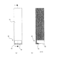
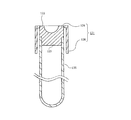
図12に、特許文献1に開示されている容器の断面図を示す。図12に示すように、栓体121は、頭部122及び密閉部123を有するゴム栓124と、このゴム栓124の外周部に固定され、減圧採血管本体125の上端部に嵌め込まれる硬質樹脂製のキャップ126とを備えて構成されている。また、キャップ126は、ゴム栓124の密閉部123よりも下方に突出している。このような構成の栓体121によれば、血液検査時に栓体121を減圧採血管本体125から取り外したときに、ゴム栓124に付着していた血液試料が検査者に付着することをキャップ126によって防ぎ、感染のおそれを低減することが可能にされている。   In FIG. 12, sectional drawing of the container currently disclosed by patent document 1 is shown. As shown in FIG. 12, the plug body 121 includes a rubber plug 124 having a head portion 122 and a sealing portion 123, and a hard resin fixed to the outer peripheral portion of the rubber plug 124 and fitted into the upper end portion of the vacuum blood collection tube main body 125. And a cap 126 made of metal. Further, the cap 126 protrudes below the sealing portion 123 of the rubber plug 124. According to the plug 121 having such a configuration, when the plug 121 is removed from the vacuum blood collection tube main body 125 at the time of blood test, the cap 126 indicates that the blood sample attached to the rubber plug 124 adheres to the examiner. It is possible to prevent and reduce the risk of infection.

このような構成によれば、1回目に開栓した瞬間にはキャップ126によって、容器内の液体がキャップ126から外へ飛散することがほぼ食い止められる。しかしながら、一度開栓した後に再び栓体121によって栓をするときや、その閉栓した状態から再び栓体121を取り外すときに、容器とゴム栓124との境界部から液体がキャップ126に飛散する可能性がある。同様に、容器に何らかの衝撃が加わったときに、キャップ126に付着していた液体が容器の外部に滴り落ちたり、飛散したりする可能性は依然として残っている。   According to such a configuration, at the moment of opening the first time, the cap 126 almost prevents the liquid in the container from splashing out of the cap 126. However, when the plug 121 is plugged again after being opened once, or when the plug 121 is removed again from the closed state, the liquid can be scattered from the boundary between the container and the rubber plug 124 to the cap 126. There is sex. Similarly, there remains a possibility that the liquid adhering to the cap 126 may drip or splash outside the container when some impact is applied to the container.

一方、検体を分析する分析装置や各種処理を行う処理装置等を含む試料検査装置においては、装置内の汚染は好ましくない。そして、このような試料検査装置が自動化されるほどその要求は大きくなる。また、試料検査装置には、複数の検体を同時に処理することによって処理速度の向上が図られたものも知られている。しかし、そのような装置は、複数の検体を同時に処理することで、装置稼動中にピペットを用いたときの溶液の飛沫やミスト等による装置内の汚染(コンタミネーション)や、検査試料やサンプル間での混入(クロス・コンタミネーション)が発生する恐れがある。したがって、複数の検体を同時に処理する試料検査装置では、コンタミネーションやクロス・コンタミネーションの発生を防止する必要がある。   On the other hand, in a sample inspection apparatus including an analysis apparatus for analyzing a specimen and a processing apparatus for performing various processes, contamination in the apparatus is not preferable. And the requirement becomes so large that such a sample inspection apparatus is automated. In addition, some sample inspection apparatuses are known in which the processing speed is improved by processing a plurality of specimens simultaneously. However, such a device processes multiple specimens at the same time, so that contamination (contamination) in the device due to droplets or mist of the solution when the pipette is used while the device is in operation, or between test samples and samples. There is a risk of contamination (cross contamination). Therefore, it is necessary to prevent the occurrence of contamination and cross contamination in a sample inspection apparatus that processes a plurality of specimens simultaneously.

ところが、容器の開口に貼られた封止フィルムのように、一度開栓してしまった後に再度閉じることが実質的に不可能な密閉方法を採用している場合には、開栓した以降は常に装置内の大気に曝された状態になってしまう。このため、封止フィルム等で容器の開口を封止する構成には、上述のクロス・コンタミネーションが発生するおそれがあった。また、上述した栓体121のように開閉可能に構成された場合であっても、キャップ126の内壁に付着した液体によって、装置内の汚染やクロス・コンタミネーションが発生するおそれがあった。
特開平06−265541号公報
However, if a sealing method that is substantially impossible to close again after being opened once, such as a sealing film attached to the opening of the container, after opening, It is always exposed to the atmosphere inside the device. For this reason, the above-described cross contamination may occur in the configuration in which the opening of the container is sealed with a sealing film or the like. Further, even when configured to be openable and closable like the plug 121 described above, there is a possibility that the liquid adhered to the inner wall of the cap 126 may cause contamination or cross contamination in the apparatus.
Japanese Patent Laid-Open No. 06-265541

上述したように、試料検査装置で用いる試薬等の試料を収容する試料容器に関しては、試料容器を一度開栓するだけでなく、分析や処理のプロセス上、必要な回数だけ開閉可能な蓋付きの構成とし、かつクロス・コンタミネーションの発生を防止する要求があった。   As described above, with respect to sample containers that contain samples such as reagents used in the sample inspection apparatus, not only the sample containers are opened once, but also with lids that can be opened and closed as many times as necessary in the process of analysis and processing. There was a demand for a configuration and to prevent the occurrence of cross contamination.

一方、蓋付き容器を、自動化された試料検査装置に採用した場合には、試料容器の蓋を開閉するための蓋開閉機構を装置内に設けることが必要になる。そのような蓋開閉機構によって試料容器の蓋を開閉する場合、図13に示すように、各容器131間に、試料の飛散を抑える遮断壁132が設けられる構成によって、検体間のクロス・コンタミネーションをある程度は防ぐことができる。しかしながら、この構成は、遮断壁132が占める高さの分だけ容器131自体の高さが高くなってしまい、装置内のスペース効率が低下してしまう。また、この構成は、容器131の高さ方向に延ばされた遮断壁132によってクロス・コンタミネーションが抑えられるものの、容器131の開口側を覆うような天井部分が無い。このため、この構成では、容器131の開口から上方に飛散する試料を遮断することができず、依然としてクロス・コンタミネーションの可能性が残っている。   On the other hand, when a container with a lid is adopted in an automated sample inspection apparatus, it is necessary to provide a lid opening / closing mechanism for opening and closing the lid of the sample container in the apparatus. When the lid of the sample container is opened and closed by such a lid opening and closing mechanism, as shown in FIG. 13, a cross-contamination between specimens is provided by a configuration in which a blocking wall 132 that suppresses scattering of the sample is provided between the containers 131. Can be prevented to some extent. However, in this configuration, the height of the container 131 itself is increased by the height occupied by the blocking wall 132, and the space efficiency in the apparatus is reduced. Further, in this configuration, although cross contamination is suppressed by the blocking wall 132 extending in the height direction of the container 131, there is no ceiling portion that covers the opening side of the container 131. For this reason, in this configuration, the sample scattered upward from the opening of the container 131 cannot be blocked, and the possibility of cross contamination still remains.

また、図12に示した栓体121のキャップ126の内壁には、溶液の飛沫等を吸収する吸収体等が設けられることで、複数回蓋を開閉する場合の液体の飛散を防止することができる。しかしながら、消耗品である容器の全てに対して、吸収体を設ける等のような構成を採ることは、製造コストの増加を招いてしまう不都合がある。   In addition, the inner wall of the cap 126 of the plug body 121 shown in FIG. 12 is provided with an absorber or the like that absorbs the droplets of the solution, thereby preventing the liquid from scattering when the lid is opened and closed a plurality of times. it can. However, adopting a configuration such as providing an absorber for all of the consumable containers has the disadvantage of increasing the manufacturing cost.

そこで、本発明は、試料容器内の試料が装置内へ飛散することを防止し、他の試料へのクロス・コンタミネーションや装置内汚染を抑えることができる蓋開閉装置、試料検査装置を提供することを目的とする。   Therefore, the present invention provides a lid opening / closing device and a sample inspection device capable of preventing the sample in the sample container from scattering into the device and suppressing cross-contamination to other samples and contamination in the device. For the purpose.

上述した目的を達成するため、本発明に係る蓋開閉装置は、試料が収納される試料容器に開閉可能に連結された蓋を開閉操作するための蓋開閉装置であって、蓋を開閉する操作部を有する蓋開閉部材と、蓋開閉部材を蓋に対して相対的に移動させる移動手段と、を備える。そして、蓋開閉部材の操作部には、蓋の周囲に飛散する試料を遮断するための遮断部が設けられている。   In order to achieve the above-described object, a lid opening / closing device according to the present invention is a lid opening / closing device for opening / closing a lid that is openably / closably connected to a sample container in which a sample is stored. A lid opening / closing member having a portion, and a moving means for moving the lid opening / closing member relative to the lid. The operating part of the lid opening / closing member is provided with a blocking unit for blocking the sample scattered around the lid.

なお、本発明における蓋開閉装置とは、蓋を開ける機能のみを備える装置、蓋を閉じる機能のみを備える装置、その両方の機能を備える装置という3つの概念を全て包括しており、蓋を開く機能と、蓋を閉じる機能の両方を備える開閉装置を限定して指すものではない。   The lid opening / closing device in the present invention includes all three concepts of a device having only the function of opening the lid, a device having only the function of closing the lid, and a device having both functions, and opens the lid. The opening / closing device having both the function and the function of closing the lid is not limited.

本発明によれば、蓋を開閉するときの蓋やその近傍に付着した試料容器内の試料が装置内へ飛散することを防止でき、他の試料へのクロス・コンタミネーションや装置内の汚染を低減することができる。   According to the present invention, it is possible to prevent the sample in the sample container adhering to or near the lid when opening and closing the lid from being scattered into the apparatus, and to prevent cross-contamination to other samples and contamination in the apparatus. Can be reduced.

以下、本発明の実施形態について図面を参照して説明する。   Embodiments of the present invention will be described below with reference to the drawings.

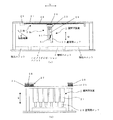
第1の実施形態の蓋開閉装置が組み込まれた遺伝子検査装置(DNA検査装置)について詳細に説明する。図1は、本実施形態の蓋開閉装置が組み込まれたDNA検査装置を示す平面図である。図2は、実施形態の蓋開閉装置が組み込まれたDNA検査装置を示す図であって、(a)が図1中A方向から示す透視側面図、(b)が図1におけるB―B断面図である。なお、図2には、蓋開閉装置及びこの蓋開閉装置に関連する部位のみを示している。   A genetic testing device (DNA testing device) incorporating the lid opening / closing device of the first embodiment will be described in detail. FIG. 1 is a plan view showing a DNA testing apparatus in which the lid opening / closing device of this embodiment is incorporated. 2A and 2B are diagrams showing a DNA testing apparatus in which the lid opening / closing device according to the embodiment is incorporated, in which FIG. 2A is a transparent side view shown in the direction A in FIG. 1, and FIG. FIG. FIG. 2 shows only the lid opening / closing device and the parts related to the lid opening / closing device.

図1に示すように、本実施形態のDNA検査装置は、抽出ユニット2と、増幅ユニット3と、ハイブリダイゼーションユニット4と、検出手段としての検出ユニット5と、を備えて構成されている。   As shown in FIG. 1, the DNA testing apparatus of this embodiment is configured to include an extraction unit 2, an amplification unit 3, a hybridization unit 4, and a detection unit 5 as detection means.

図1に示すように、抽出ユニット2は、シリカコーティングされた磁性ビーズを使用し、シリカコーティングにDNAのみを吸着することで、試料(サンプル)からDNAだけを取り出している。増幅ユニット3は、抽出ユニット2によって抽出されたDNAを94℃で一本鎖にし、50℃〜70℃でDNAポリメラーゼと合成することを繰り返し、サンプルDNAを「2」の20〜30乗倍に増加させる。ハイブリダイゼーションユニット4は、増幅ユニット3によって増やしたサンプルDNAに対して、溶液塩濃度と温度を制御し、また不要なDNAは解離させ、基板上プローブと一本鎖を対合させている。検出ユニット5は、ハイブリダイゼーションユニット4によってハイブリダイゼーションさせたサンプル基板にレーザー光を照射してスポットを励起し、センサで検出することで、励起した蛍光スポットを光学的に検出する。   As shown in FIG. 1, the extraction unit 2 uses silica-coated magnetic beads and adsorbs only DNA to the silica coating, thereby extracting only the DNA from the sample (sample). The amplification unit 3 repeats synthesizing the DNA extracted by the extraction unit 2 into a single strand at 94 ° C. and synthesizing with DNA polymerase at 50 ° C. to 70 ° C. increase. The hybridization unit 4 controls the solution salt concentration and temperature with respect to the sample DNA increased by the amplification unit 3, and dissociates unnecessary DNA to pair the probe with the single strand on the substrate. The detection unit 5 optically detects the excited fluorescent spot by irradiating the sample substrate hybridized by the hybridization unit 4 with laser light to excite the spot and detecting it with a sensor.

また、本実施形態のDNA検査装置は、抽出ユニット用のピペッター6、試薬入り容器(試料容器)、ピペットチップ、反応槽等の器具9を備えている。抽出ユニット用のピペッター6は、これら器具9の間を矢印C方向に移動することで、液体のハンドリングを行う。   In addition, the DNA testing apparatus of the present embodiment includes an extraction unit pipetter 6, a reagent-containing container (sample container), a pipette chip, a reaction tank, and other instruments 9. The pipetter 6 for the extraction unit moves between the instruments 9 in the direction of arrow C, thereby handling the liquid.

また、本実施形態のDNA検査装置は、増幅ユニット用のピペッター7、試薬入り容器、ピペットチップ、反応槽等の器具10を備えている。増幅ユニット用のピペッター7は、これら器具10と、抽出ユニット2と、ハイブリダイゼーションユニット4との間を矢印C方向に移動することで、液体のハンドリングを行う。なお、器具10の載置部は、矢印D方向に移動可能に構成されており、ユーザーが器具10を載置部にセットした後に、所定の位置に移動する。   In addition, the DNA testing apparatus of this embodiment includes a pipetter 7 for an amplification unit, a reagent-containing container, a pipette chip, and a device 10 such as a reaction tank. The amplification unit pipettor 7 moves between these instruments 10, the extraction unit 2, and the hybridization unit 4 in the direction of arrow C, thereby handling the liquid. In addition, the mounting part of the instrument 10 is configured to be movable in the direction of arrow D, and moves to a predetermined position after the user sets the instrument 10 on the mounting part.

また、本実施形態のDNA検査装置は、ハイブリダイゼーションユニット用のピペッター8、試薬入り容器、ピペットチップ等の器具11、サンプル基板が内蔵されたカセット12を備えている。ハイブリダイゼーションユニット用のピペッター8は、これらの器具11の間を矢印C方向に移動することで、液体のハンドリングを行う。なお、器具11及びカセット12の載置部は、矢印D方向に対して移動可能に設けられており、ユーザーが器具11及びカセット12を載置部にセットした後、所定の位置に移動される。   In addition, the DNA testing apparatus of this embodiment includes a pipetter 8 for a hybridization unit, a reagent-containing container, an instrument 11 such as a pipette chip, and a cassette 12 in which a sample substrate is built. The pipettor 8 for the hybridization unit moves between these instruments 11 in the direction of arrow C, thereby handling the liquid. In addition, the mounting part of the instrument 11 and the cassette 12 is provided so as to be movable in the direction of the arrow D, and is moved to a predetermined position after the user sets the instrument 11 and the cassette 12 on the mounting part. .

また、カセット12は、ハイブリダイゼーション後に、搬送ハンド13によって検出ユニット5に移送され、検出ユニット5によって検出が行われる。検出が行われた後、カセット12は、DNA検査装置外に移送されて廃棄される。   Further, after hybridization, the cassette 12 is transferred to the detection unit 5 by the transport hand 13 and detected by the detection unit 5. After detection is performed, the cassette 12 is transferred out of the DNA testing apparatus and discarded.

なお、器具9、10、11の試薬入り容器や反応槽は、液漏れ、飛散、蒸発、核酸飛散、核酸混入、異物混入等を防ぐために、必要に応じて蓋付きの容器が用いられている。器具9、10、11における、試料が収納される蓋付きの試料容器40は、開口を開閉可能に連結された蓋41を有している。また、器具9、10、11における複数の試料容器40は、隣接して配置されている。   In addition, the containers with reagents and the reaction vessels of the instruments 9, 10, and 11 use containers with lids as necessary in order to prevent liquid leakage, scattering, evaporation, nucleic acid scattering, nucleic acid contamination, foreign matter contamination, and the like. . A sample container 40 with a lid for storing a sample in the instruments 9, 10, 11 has a lid 41 that is connected so that the opening can be opened and closed. Moreover, the several sample container 40 in the instrument 9,10,11 is arrange | positioned adjacently.

本実施形態のDNA検査装置は、図1に示すように、上述した各器具9、10、11に含まれる試料容器40の蓋41を開閉操作するための蓋開閉装置1を備えている。この蓋開閉装置1は、図1及び図2(a)、(b)に示すように、試料容器40の蓋41を開閉する複数の蓋開閉部材としての蓋開閉ロッド20と、これら各蓋開閉ロッド20を蓋41に対して相対的に移動させる移動手段としての移動機構29とを備えている。   As shown in FIG. 1, the DNA testing apparatus of the present embodiment includes a lid opening / closing device 1 for opening and closing the lid 41 of the sample container 40 included in each of the instruments 9, 10, 11 described above. As shown in FIGS. 1 and 2A and 2B, the lid opening / closing device 1 includes a lid opening / closing rod 20 as a plurality of lid opening / closing members for opening / closing the lid 41 of the sample container 40, and each of these lid opening / closing rods. A moving mechanism 29 is provided as a moving means for moving the rod 20 relative to the lid 41.

なお、図2(b)に示したように、本実施形態の蓋開閉装置1は、6つの蓋開閉ロッド20を備える6連の構成を採っているが、少なくとも1つの蓋開閉ロッド20を備えていれば、本発明に本質的な差異はない。さらに、本実施形態の蓋開閉装置1は、蓋開閉ロッド20によって、試料容器40の開口に対して蓋41を開ける機能と、蓋41を閉じる機能とを併せ持っている。   As shown in FIG. 2B, the lid opening / closing device 1 of the present embodiment has a six-unit configuration including six lid opening / closing rods 20, but includes at least one lid opening / closing rod 20. If so, there is no essential difference in the present invention. Furthermore, the lid opening / closing device 1 of the present embodiment has both a function of opening the lid 41 with respect to the opening of the sample container 40 and a function of closing the lid 41 by the lid opening / closing rod 20.

図2(a)、(b)に示すように、蓋開閉ロッド20は、移動機構29を介して、互いに直交する2軸方向である矢印Q方向及び矢印H方向に移動可能に支持されている。この移動機構29は、モーター22、タイミングベルト23、プーリー24を有する第1移動機構29aと、スライダー25、スライダーレール26を有する第2移動機構29bとを備えている。スライダー25は、基台21を支持しており、リードスクリュー27に螺合されるナット部を有し、モーター28からの駆動力によって矢印H方向に移動される。   As shown in FIGS. 2A and 2B, the lid opening / closing rod 20 is supported via a moving mechanism 29 so as to be movable in the directions of arrows Q and H that are biaxial directions perpendicular to each other. . The moving mechanism 29 includes a first moving mechanism 29 a having a motor 22, a timing belt 23, and a pulley 24, and a second moving mechanism 29 b having a slider 25 and a slider rail 26. The slider 25 supports the base 21, has a nut portion that is screwed to the lead screw 27, and is moved in the arrow H direction by a driving force from the motor 28.

図3は、蓋開閉ロッド20を示す詳細図である。図3(a)、(b)に示すように、蓋開閉ロッド20の下端には、蓋41を開閉操作するための断面略L字状の操作部30が形成されている。蓋開閉ロッド20は、蓋41を開けるときに、操作部30が蓋41に当接される(図5(b)、(c)参照)。   FIG. 3 is a detailed view showing the lid opening / closing rod 20. As shown in FIGS. 3A and 3B, an operation portion 30 having a substantially L-shaped cross section for opening and closing the lid 41 is formed at the lower end of the lid opening / closing rod 20. When the lid 41 is opened, the operating portion 30 is brought into contact with the lid 41 (see FIGS. 5B and 5C).

また、この操作部30には、試料容器40の開口を開閉操作するときに、蓋41の周囲に飛散する試料を遮断するための遮断部としての側壁34及び側壁35が、蓋41を包囲するように形成されている。また、操作部30には、試料容器40の開口に対向する天面36が形成されている。すなわち、操作部30には、側壁34及び側壁35、天面36が、蓋41の試料容器40との連結側を除いて、蓋41の天面と側面を包囲するように形成されている。したがって、これら側壁34及び側壁35、天面36によって、操作部30が蓋41を開閉操作するときに、試料の飛散が防止されている。   In addition, when the opening of the sample container 40 is opened and closed in the operation unit 30, the side wall 34 and the side wall 35 as a blocking unit for blocking the sample scattered around the lid 41 surround the lid 41. It is formed as follows. In addition, the operation unit 30 has a top surface 36 that faces the opening of the sample container 40. That is, the operation unit 30 is formed with the side wall 34, the side wall 35, and the top surface 36 so as to surround the top surface and the side surface of the lid 41 except for the connection side of the lid 41 to the sample container 40. Therefore, the side wall 34, the side wall 35, and the top surface 36 prevent the sample from being scattered when the operation unit 30 opens and closes the lid 41.

また、必要に応じて、蓋開閉ロッド20の外周面33を蓋41に当接させることで、この外周面33によって蓋41の回動を補助する場合もある。また、図7及び図8に示すように、蓋開閉ロッド20は、操作部30の外周面31、底面32によって蓋41を押し込むことで、蓋41を閉じる。   Further, if necessary, the outer peripheral surface 33 of the lid opening / closing rod 20 may be brought into contact with the lid 41 to assist the rotation of the lid 41. As shown in FIGS. 7 and 8, the lid opening / closing rod 20 closes the lid 41 by pushing the lid 41 with the outer peripheral surface 31 and the bottom surface 32 of the operation unit 30.

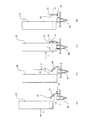
以下、蓋開閉装置1の蓋開閉ロッド20によって蓋41を開けるときの動作を、動作順にそれぞれ示す図5(a)〜(d)及び図6(a)〜(d)を参照して説明する。   Hereinafter, the operation when the lid 41 is opened by the lid opening / closing rod 20 of the lid opening / closing device 1 will be described with reference to FIGS. 5A to 5D and FIGS. .

図5(a)に示すように、蓋開閉ロッド20を矢印I方向から蓋41に近づけることによって、樹脂製の試料容器40(器具9、10、11のうちの蓋付き容器)の蓋41の下方に、操作部30を入り込ませる。続いて、図5(b)に示すように、蓋開閉ロッド20を矢印K方向に上昇させることで、操作部30によって蓋41の当接部42を矢印K方向に持ち上げる。このように、蓋開閉ロッド20の操作部30によって蓋41の当接部42が移動されることで、図5(c)及び図5(d)に示すように、蓋41は、ヒンジ部43を回動中心として矢印J方向に回動を開始する。このとき、蓋41は、回動されるのに伴って、試料容器40の開口を密閉した状態で圧入されていた圧入部44が、試料容器40の開口から離れ始める。   As shown in FIG. 5A, the lid opening / closing rod 20 is moved closer to the lid 41 in the direction of arrow I, so that the lid 41 of the resin sample container 40 (the container with the lid among the instruments 9, 10 and 11) can be removed. The operation unit 30 is inserted below. Subsequently, as shown in FIG. 5B, the lid opening / closing rod 20 is raised in the direction of the arrow K, whereby the contact portion 42 of the lid 41 is lifted in the direction of the arrow K by the operation unit 30. As described above, when the contact portion 42 of the lid 41 is moved by the operation portion 30 of the lid opening / closing rod 20, the lid 41 has the hinge portion 43 as shown in FIGS. 5 (c) and 5 (d). Rotation is started in the direction of arrow J with the center of rotation. At this time, as the lid 41 is rotated, the press-fit portion 44 that has been press-fitted in a state where the opening of the sample container 40 is sealed begins to move away from the opening of the sample container 40.

なお、蓋41は、ヒンジ部43の回動中心付近の部分が、樹脂材によって厚さが数100μm程度の薄肉状に形成されており、塑性変形しながらも所定の耐久回数は破断しないように、試料容器40に一体に連結されて形成されている。なお、このような構成に限定されるものではなく、試料容器と蓋とを別体で形成し、試料容器に蓋が回動可能に組み付けられて構成されてもよい。   In addition, the cover 41 is formed in a thin shape with a thickness of about several hundreds μm by a resin material in the vicinity of the rotation center of the hinge portion 43 so that the predetermined endurance number is not broken while being plastically deformed. , Formed integrally with the sample container 40. In addition, it is not limited to such a structure, A sample container and a lid | cover may be formed separately, and the lid | cover may be assembled | attached to a sample container so that rotation is possible.

また、蓋41に矢印J方向への付勢力を持たせるために、ヒンジ部43の形状を最適化したり、試料容器と蓋とが別体に構成された場合には、ねじりコイルバネ等の付勢部材が組み込まれる構成が採られてもよい。本実施形態において、蓋41は、容器の開口から離れて開く方向である矢印J方向への付勢力を有しており、矢印J方向に開いた所定の位置においてその位置を保つように形成されている。   Further, in order to give the lid 41 a biasing force in the direction of the arrow J, when the shape of the hinge portion 43 is optimized, or when the sample container and the lid are configured separately, a biasing force such as a torsion coil spring is applied. A configuration in which the member is incorporated may be employed. In the present embodiment, the lid 41 has an urging force in the direction of arrow J, which is a direction to open away from the opening of the container, and is formed so as to maintain its position at a predetermined position opened in the direction of arrow J. ing.

さらに、蓋開閉ロッド20を矢印K方向に持ち上げたとき、蓋41は、試料容器40の開口から離間し、試料容器40から離れた所定の位置で停止する。仮に、蓋41が停止した位置がピペッターによる分注動作の妨げになる場合には、試料容器40の開口から蓋41を更に離間させるために、蓋開閉ロッド20によって、図6(a)〜(d)に示す動作を行う。すなわち、図5(d)に示した状態から、図6(a)に示すように、蓋開閉ロッド20を矢印I’方向に一旦移動させることで、蓋41から離れさせる。蓋開閉ロッド20を矢印I’方向に移動させた後、図6(b)に示すように、蓋開閉ロッド20を矢印K’方向に下降させることで、外周面33を蓋41の当接部42に突き当てることができる位置に移動させる。   Further, when the lid opening / closing rod 20 is lifted in the arrow K direction, the lid 41 is separated from the opening of the sample container 40 and stops at a predetermined position away from the sample container 40. If the position where the lid 41 is stopped hinders the pipetting operation by the pipetter, the lid opening / closing rod 20 may be used to further separate the lid 41 from the opening of the sample container 40. The operation shown in d) is performed. That is, from the state shown in FIG. 5 (d), as shown in FIG. 6 (a), the lid opening / closing rod 20 is once moved in the direction of the arrow I 'to be separated from the lid 41. After the lid opening / closing rod 20 is moved in the direction of arrow I ′, as shown in FIG. 6B, the lid opening / closing rod 20 is lowered in the direction of arrow K ′, so that the outer peripheral surface 33 is brought into contact with the lid 41. It is moved to a position where it can abut against 42.

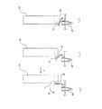
次に、図6(c)に示すように、蓋開閉ロッド20を矢印I方向に移動させることによって、蓋41を更に矢印J方向に回動させる。その後、蓋41と蓋開閉ロッド20との接触状態がなくなっても、蓋41は、ヒンジ部43の塑性変形に伴う保持力によって、図6(d)に示すように、試料容器40の開口に対するピペッターの動作を妨げない位置に退避されたままの状態が保持される。なお、このとき、蓋41の当接部42は、圧入部44の位置よりも蓋開閉ロッド20側の位置、つまり試料容器40の開口側に向かって突出されているので、圧入部44に付着した内溶液が蓋開閉ロッド20に付着することを防いでいる。また、試料容器40は、蓋開閉ロッド20による蓋開閉動作によって浮きが生じないように、不図示の押さえ部材によって装置に固定されている。   Next, as shown in FIG. 6C, the lid 41 is further rotated in the arrow J direction by moving the lid opening / closing rod 20 in the arrow I direction. Thereafter, even if the contact state between the lid 41 and the lid opening / closing rod 20 disappears, the lid 41 is held against the opening of the sample container 40 by the holding force accompanying the plastic deformation of the hinge portion 43 as shown in FIG. The state of being retracted to a position that does not hinder the operation of the pipetter is maintained. At this time, the abutting portion 42 of the lid 41 protrudes toward the position of the lid opening / closing rod 20 from the position of the press-fit portion 44, that is, toward the opening side of the sample container 40. This prevents the inner solution from adhering to the lid opening / closing rod 20. Further, the sample container 40 is fixed to the apparatus by a pressing member (not shown) so as not to be lifted by the lid opening / closing operation by the lid opening / closing rod 20.

次に、蓋開閉装置1の蓋開閉ロッド20によって蓋41を閉めるときの動作を、動作順にそれぞれ示す図7(a)〜(c)及び図8(a),(b)を参照して説明する。   Next, the operation when the lid 41 is closed by the lid opening / closing rod 20 of the lid opening / closing apparatus 1 will be described with reference to FIGS. 7A to 7C and FIGS. To do.

まず、図7(a)に示すように、試料容器40の開口に対して開いた蓋41に向かって、蓋開閉ロッド20を矢印L方向に移動させることで、蓋41に近づけて、外周面31を蓋41の天面に突き当てる。   First, as shown in FIG. 7 (a), the lid opening / closing rod 20 is moved in the direction of arrow L toward the lid 41 opened with respect to the opening of the sample container 40, thereby bringing the outer surface closer to the lid 41. 31 is abutted against the top surface of the lid 41.

続いて、図7(b)及び図7(c)に示すように、蓋開閉ロッド20を更に矢印L方向に移動させることで、外周面31によって蓋41を矢印M方向に回動させる。引き続き、図8(a)に示すように、蓋開閉ロッド20を矢印N方向に下降させることで、蓋開閉ロッド20の底面32によって、蓋41を更に矢印M方向に回動させる。そして、蓋開閉ロッド20の底面32によって蓋41を矢印N方向に押し込むことで、蓋41の圧入部44を試料容器40の開口に圧入する。蓋41は、ヒンジ部43による付勢力によって、矢印P方向に開く付勢力が働いているが、この付勢力が、圧入部44を開口から引き抜くのに要する力よりも小さい。このため、図8(b)に示すように、蓋開閉ロッド20の操作部30を蓋41から離した後も、蓋41は試料容器40を密閉した状態を保持している。   Subsequently, as shown in FIGS. 7B and 7C, the lid opening / closing rod 20 is further moved in the arrow L direction, so that the lid 41 is rotated in the arrow M direction by the outer peripheral surface 31. Subsequently, as shown in FIG. 8A, the lid 41 is further rotated in the arrow M direction by the bottom surface 32 of the lid opening / closing rod 20 by lowering the lid opening / closing rod 20 in the arrow N direction. Then, by pressing the lid 41 in the direction of arrow N by the bottom surface 32 of the lid opening / closing rod 20, the press-fit portion 44 of the lid 41 is press-fitted into the opening of the sample container 40. The lid 41 has a biasing force that opens in the direction of the arrow P due to the biasing force of the hinge portion 43, but this biasing force is smaller than the force required to pull out the press-fit portion 44 from the opening. For this reason, as shown in FIG. 8B, the lid 41 keeps the sample container 40 sealed even after the operating portion 30 of the lid opening / closing rod 20 is separated from the lid 41.

以上の蓋開閉ロッド20の動作によって蓋41の開閉を行うが、蓋41を開くときに、蓋41と試料容器40との接触部分、及びその付近には内溶液が付着している場合がある。このような場合には、図5(b)及び図5(c)に示す動作時に、蓋41を開くときに生じる衝撃によって内溶液が飛散する可能性がある。本実施形態によれば、図3(a)に示すように、蓋開閉ロッド20の操作部30に、側壁34及び側壁35が蓋41を包囲するように設けられたことで、側壁34及び側壁35によって液体が矢印S1、S2方向及びS4、S5方向に飛散することが遮断される。また、矢印S3方向への飛散は、蓋41自体によって遮断される。   The lid 41 is opened and closed by the operation of the lid opening / closing rod 20 described above. When the lid 41 is opened, the inner solution may adhere to the contact portion between the lid 41 and the sample container 40 and the vicinity thereof. . In such a case, there is a possibility that the inner solution may scatter due to the impact generated when the lid 41 is opened during the operation shown in FIGS. 5B and 5C. According to the present embodiment, as shown in FIG. 3A, the side wall 34 and the side wall 35 are provided on the operation portion 30 of the lid opening / closing rod 20 so as to surround the lid 41. 35 prevents the liquid from splashing in the directions of arrows S1, S2 and S4, S5. Further, scattering in the direction of the arrow S3 is blocked by the lid 41 itself.

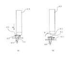
図4(a),(b)に示すように、蓋開閉ロッド20の操作部3には、飛散試料落下防止手段としての複数の溝50が、水平方向に沿って側壁34、35に亘って形成された構成を示している。この蓋開閉ロッド20によれば、各溝50で発生する毛細管力によって、飛散した液体を吸引して保持し、装置内を汚染することを防いでいる。   As shown in FIGS. 4A and 4B, the operation portion 3 of the lid opening / closing rod 20 has a plurality of grooves 50 serving as scattering sample dropping prevention means across the side walls 34 and 35 along the horizontal direction. The formed structure is shown. According to the lid opening / closing rod 20, the scattered liquid is sucked and held by the capillary force generated in each groove 50, and the inside of the apparatus is prevented from being contaminated.

また、図9(a),(b)に示すように、蓋開閉ロッド20の操作部30の側壁35に、吸収体51を配置する構成が採られてもよく、蓋41の周囲への試料の飛散を防止することができる。また、図10(a),(b)に示すように、操作部30の下端には、庇状に水平方向に延ばされた突出壁52が設けられる構成が採られてもよいことは勿論であり、この突出壁52によって、蓋41の周囲への液体の飛散を防止することができる。   Further, as shown in FIGS. 9A and 9B, a configuration may be adopted in which an absorber 51 is disposed on the side wall 35 of the operation unit 30 of the lid opening / closing rod 20. Can be prevented. Further, as shown in FIGS. 10A and 10B, the lower end of the operation unit 30 may of course be provided with a protruding wall 52 that extends horizontally in a bowl shape. Thus, the protruding wall 52 can prevent the liquid from scattering around the lid 41.

また、蓋開閉ロッド20は、上述した構成のような、蓋41に直接接触させる構成に限らず、例えば電磁力によって開閉操作するように構成されてもよい。例えば図11(a),(b)に示すように、蓋41には、着磁板60が設けられ、蓋開閉ロッド20には、蓋開き用の電磁石61及び蓋閉じ用の電磁石62がそれぞれ配置され、それらを適宜通電することで、蓋41を開閉させるように構成されてもよい。   Moreover, the lid | cover opening / closing rod 20 is not restricted to the structure which contacts the lid | cover 41 directly like the structure mentioned above, For example, you may be comprised so that opening / closing operation may be carried out by electromagnetic force. For example, as shown in FIGS. 11A and 11B, the lid 41 is provided with a magnetized plate 60, and the lid opening / closing rod 20 has an electromagnet 61 for opening the lid and an electromagnet 62 for closing the lid, respectively. The lid 41 may be configured to be opened and closed by appropriately energizing them.

なお、本実施形態では、蓋41を閉じるときに試料容器40の開口からの飛散する可能性がある飛散液体を遮断するための遮断壁が設けられる構成が採られていないが、そのような遮断壁が蓋開閉ロッド20の操作部30に設けられてもよいことは勿論である。   In addition, in this embodiment, when the lid | cover 41 is closed, the structure provided with the interruption | blocking wall for interrupting | spattering the scattering liquid which may be scattered from opening of the sample container 40 is not taken, but such interruption | blocking is taken. Of course, a wall may be provided in the operation unit 30 of the lid opening / closing rod 20.

以上のように、本実施形態の蓋開閉装置1によれば、蓋41を開閉操作する蓋開閉ロッド20の操作部30に、側壁34、35、天面36が形成されたことで、蓋41を開閉するときの蓋41やその近傍に付着した試料容器40内の試料(液体)が装置内へ飛散することを防止でき、他の検体へのクロス・コンタミネーションや装置内の汚染を低減することができる。   As described above, according to the lid opening / closing device 1 of the present embodiment, the side walls 34, 35 and the top surface 36 are formed on the operation portion 30 of the lid opening / closing rod 20 that opens and closes the lid 41. It is possible to prevent the sample (liquid) in the sample container 40 adhering to or near the lid 41 when opening and closing the container from being scattered into the apparatus, and to reduce cross-contamination to other specimens and contamination in the apparatus. be able to.

なお、上述した実施形態の蓋開閉装置では、移動機構29によって蓋開閉ロッド20が移動される構成が採られたが、固定された蓋開閉ロッドに対して蓋側が移動される構成にされてもよい。また、蓋開閉装置は、蓋開閉ロッド側が第1移動機構によって移動されるとともに、蓋側が第2移動機構によって移動される構成が採られてもよい。   In the lid opening / closing device of the above-described embodiment, the configuration in which the lid opening / closing rod 20 is moved by the moving mechanism 29 is adopted, but the lid side may be moved with respect to the fixed lid opening / closing rod. Good. Further, the lid opening / closing device may be configured such that the lid opening / closing rod side is moved by the first movement mechanism and the lid side is moved by the second movement mechanism.

また、本発明に係る試料検査装置は、上述したDNA検査装置に限定されるものではなく、各種の試料を分析する分析装置や、試料に処理する処理装置に適用されて好適である。   In addition, the sample inspection apparatus according to the present invention is not limited to the above-described DNA inspection apparatus, and is preferably applied to an analysis apparatus that analyzes various samples and a processing apparatus that processes the samples.

本実施形態の蓋開閉装置が組み込まれたDNA検査装置を示す平面図である。It is a top view which shows the DNA test | inspection apparatus with which the lid | cover opening / closing apparatus of this embodiment was integrated. 本実施形態の蓋開閉装置を示す全体図である。It is a general view which shows the lid | cover opening / closing apparatus of this embodiment. 蓋開閉ロッドを示す図である。It is a figure which shows a lid | cover opening / closing rod. 複数の溝を有する蓋開閉ロッドを示す図である。It is a figure which shows the lid | cover opening / closing rod which has a some groove | channel. 蓋開閉ロッドによって蓋を開ける動作を説明するための図である。It is a figure for demonstrating the operation | movement which opens a lid | cover with a lid | cover opening / closing rod. 蓋開閉ロッドによって蓋を開ける動作を説明するための図である。It is a figure for demonstrating the operation | movement which opens a lid | cover with a lid | cover opening / closing rod. 蓋開閉ロッドによって蓋を閉じる動作を説明するための図である。It is a figure for demonstrating the operation | movement which closes a lid | cover with a lid | cover opening / closing rod. 蓋開閉ロッドによって蓋を閉じる動作を説明するための図である。It is a figure for demonstrating the operation | movement which closes a lid | cover with a lid | cover opening / closing rod. 吸収体が設けられた蓋開閉ロッドを示す図である。It is a figure which shows the lid | cover opening / closing rod provided with the absorber. 庇状の突出部が設けられた蓋開閉ロッドを示す図である。It is a figure which shows the lid | cover opening / closing rod provided with the hook-shaped protrusion part. 電磁石を備える蓋開閉ロッド、及び着磁板を備える容器を示す図である。It is a figure which shows the container provided with the lid | cover opening / closing rod provided with an electromagnet, and a magnetized board. 従来の容器内液体飛散防止構造を説明するための断面図である。It is sectional drawing for demonstrating the conventional liquid scattering prevention structure in a container. 従来の容器内液体飛散防止構造を説明するための斜視図である。It is a perspective view for demonstrating the conventional liquid scattering prevention structure in a container.

符号の説明Explanation of symbols

1 蓋開閉装置
20 蓋開閉ロッド
29 移動機構
30 操作部
34、35 側壁
40 試料容器
41 蓋
43 ヒンジ部
DESCRIPTION OF SYMBOLS 1 Lid opening / closing apparatus 20 Lid opening / closing rod 29 Moving mechanism 30 Operation part 34, 35 Side wall 40 Sample container 41 Lid 43 Hinge part

Claims (10)

試料が収納される試料容器に開閉可能に連結された蓋を開閉操作するための蓋開閉装置であって、
前記蓋を開閉する操作部を有する蓋開閉部材と、
前記蓋開閉部材を前記蓋に対して相対的に移動させる移動手段と、を備え、
前記蓋開閉部材の前記操作部には、前記蓋の周囲に飛散する試料を遮断するための遮断部が設けられている、ことを特徴とする蓋開閉装置。
A lid opening and closing device for opening and closing a lid that is openably and closably connected to a sample container in which a sample is stored,
A lid opening / closing member having an operation part for opening and closing the lid;
Moving means for moving the lid opening / closing member relative to the lid,
The lid opening / closing apparatus, wherein the operation part of the lid opening / closing member is provided with a blocking unit for blocking a sample scattered around the lid.
隣接して配置された複数の前記試料容器に対して前記各蓋を同時に開閉操作する複数の前記蓋開閉部材を備える、請求項1に記載の蓋開閉装置。   The lid opening / closing apparatus according to claim 1, further comprising: a plurality of lid opening / closing members that simultaneously open / close the lids with respect to the plurality of sample containers arranged adjacent to each other. 前記遮断部は、前記蓋の前記試料容器との連結側を除いて、前記蓋の天面と側面を包囲するように形成されている、請求項1又は2に記載の蓋開閉装置。   3. The lid opening / closing apparatus according to claim 1, wherein the blocking portion is formed so as to surround a top surface and a side surface of the lid except for a side of the lid connected to the sample container. 前記遮断部には、前記蓋側の面に、飛散試料落下防止手段が設けられている、請求項1ないし3のいずれか1項に記載の蓋開閉装置。   The lid opening / closing device according to any one of claims 1 to 3, wherein a scattering sample fall prevention means is provided on the surface on the lid side of the blocking portion. 前記飛散試料落下防止手段は、毛細管力を発生する溝を有する、請求項4に記載の蓋開閉装置。   The lid opening / closing apparatus according to claim 4, wherein the scattering sample dropping prevention means has a groove for generating a capillary force. 複数の前記溝が水平方向に沿って設けられている、請求項5に記載の蓋開閉装置。   The lid opening / closing device according to claim 5, wherein the plurality of grooves are provided along a horizontal direction. 前記飛散試料落下防止手段は、吸収体を有する、請求項4に記載の蓋開閉装置。   The lid opening / closing device according to claim 4, wherein the scattered sample dropping prevention means includes an absorber. 前記飛散試料落下防止手段は、庇状に水平方向に延ばされた突出壁を有する、請求項4に記載の蓋開閉装置。   The lid opening / closing device according to claim 4, wherein the scattered sample dropping prevention means has a protruding wall extending in a horizontal direction in a bowl shape. 前記移動手段は、前記蓋開閉部材を互いに直交する2軸方向に移動可能に支持する、請求項1ないし8のいずれか1項に記載の蓋開閉装置。   The lid opening / closing device according to any one of claims 1 to 8, wherein the moving means supports the lid opening / closing member so as to be movable in two axial directions orthogonal to each other. 請求項1ないし9のいずれか1項に記載の前記蓋開閉装置と、試料を検査する検査手段とを備える試料検査装置。   A sample inspection apparatus comprising: the lid opening / closing device according to any one of claims 1 to 9; and inspection means for inspecting the sample.
JP2007283520A 2007-10-31 2007-10-31 Lid opening/closing device, and sample inspection apparatus Pending JP2009109403A (en)

Priority Applications (1)

Application Number Priority Date Filing Date Title
JP2007283520A JP2009109403A (en) 2007-10-31 2007-10-31 Lid opening/closing device, and sample inspection apparatus

Applications Claiming Priority (1)

Application Number Priority Date Filing Date Title
JP2007283520A JP2009109403A (en) 2007-10-31 2007-10-31 Lid opening/closing device, and sample inspection apparatus

Publications (1)

Publication Number Publication Date
JP2009109403A true JP2009109403A (en) 2009-05-21

Family

ID=40778029

Family Applications (1)

Application Number Title Priority Date Filing Date
JP2007283520A Pending JP2009109403A (en) 2007-10-31 2007-10-31 Lid opening/closing device, and sample inspection apparatus

Country Status (1)

Country Link
JP (1) JP2009109403A (en)

Cited By (7)

* Cited by examiner, † Cited by third party
Publication number Priority date Publication date Assignee Title
WO2011074472A1 (en) * 2009-12-14 2011-06-23 株式会社 日立ハイテクノロジーズ Automatic analyzing device and device for opening and closing cover of reagent container therein
JP2012098139A (en) * 2010-11-02 2012-05-24 Hitachi High-Technologies Corp Reagent container lid open/close mechanism and automatic analysis device having the same
JP2013134070A (en) * 2011-12-26 2013-07-08 Hitachi High-Technologies Corp Container stopper and nucleic acid analyzer with the same
WO2014166980A1 (en) * 2013-04-09 2014-10-16 Qiagen Gmbh Closing arrangement and method of closing tube
WO2016136289A1 (en) * 2015-02-26 2016-09-01 株式会社日立ハイテクノロジーズ Automated analysis device, and lid opening/closing mechanism
WO2017018163A1 (en) * 2015-07-27 2017-02-02 株式会社日立ハイテクノロジーズ Automated analyzer
JP7150929B1 (en) * 2021-04-14 2022-10-11 株式会社椿本チエイン tube decapper

Cited By (18)

* Cited by examiner, † Cited by third party
Publication number Priority date Publication date Assignee Title
CN102652262A (en) * 2009-12-14 2012-08-29 株式会社日立高新技术 Automatic analyzing device and device for opening and closing cover of reagent container therein
US8703056B2 (en) 2009-12-14 2014-04-22 Hitachi High-Technologies Corporation Automated analyzer and device for opening/closing the lids of reagent vessels
JP5726091B2 (en) * 2009-12-14 2015-05-27 株式会社日立ハイテクノロジーズ Automatic analyzer and lid opening / closing device for reagent container
WO2011074472A1 (en) * 2009-12-14 2011-06-23 株式会社 日立ハイテクノロジーズ Automatic analyzing device and device for opening and closing cover of reagent container therein
JP2012098139A (en) * 2010-11-02 2012-05-24 Hitachi High-Technologies Corp Reagent container lid open/close mechanism and automatic analysis device having the same
JP2013134070A (en) * 2011-12-26 2013-07-08 Hitachi High-Technologies Corp Container stopper and nucleic acid analyzer with the same
AU2014253162B2 (en) * 2013-04-09 2018-11-15 Qiagen Gmbh Closing arrangement and method of closing tube
WO2014166980A1 (en) * 2013-04-09 2014-10-16 Qiagen Gmbh Closing arrangement and method of closing tube
JP2016514483A (en) * 2013-04-09 2016-05-23 キアゲン ゲーエムベーハー Closure array and method of closing a tube
US10376887B2 (en) 2013-04-09 2019-08-13 Qiagen Gmbh Closing arrangement and method of closing tube
WO2016136289A1 (en) * 2015-02-26 2016-09-01 株式会社日立ハイテクノロジーズ Automated analysis device, and lid opening/closing mechanism
JPWO2016136289A1 (en) * 2015-02-26 2017-12-07 株式会社日立ハイテクノロジーズ Automatic analyzer and lid opening / closing mechanism
CN107110878A (en) * 2015-02-26 2017-08-29 株式会社日立高新技术 Automatic analysing apparatus and lid switching mechanism
US10670618B2 (en) 2015-02-26 2020-06-02 Hitachi High-Tech Corporation Automated analysis device, and lid opening/closing mechanism
JPWO2017018163A1 (en) * 2015-07-27 2018-04-26 株式会社日立ハイテクノロジーズ Automatic analyzer
WO2017018163A1 (en) * 2015-07-27 2017-02-02 株式会社日立ハイテクノロジーズ Automated analyzer
US10605818B2 (en) 2015-07-27 2020-03-31 Hitachi High-Technologies Corporation Automated analyzer
JP7150929B1 (en) * 2021-04-14 2022-10-11 株式会社椿本チエイン tube decapper

Similar Documents

Publication Publication Date Title
JP2009109403A (en) Lid opening/closing device, and sample inspection apparatus
US10351843B2 (en) System for separating and detecting an analyte
EP2333559B1 (en) Nucleic acid analysis method and automated nucleic acid analyzer with spatial separation
EP2338597B1 (en) Multiwell plate and lid
EP2338596B1 (en) Tip rack
JP4959450B2 (en) Chemical analyzer
US20190154716A1 (en) Hardware architecture of analyzers
EP2333558B1 (en) Form-locking gripping system
US20230202725A1 (en) Automation compatible removable lids and methods of use
EP2338600A1 (en) Process head positioning
EP2629098A1 (en) Workflow timing between modules
JP5216820B2 (en) Dispensing device and nucleic acid analyzer
US20230258676A1 (en) Automated analytical system for processing biological samples
JP2008298493A (en) Autoanalyzer
JP6871935B2 (en) Automatic analysis system for in vitro diagnosis
JP5097721B2 (en) Automatic analyzer
GB2547484A (en) Device and method for assay processing within an analyzer system
EP4234677A1 (en) Analysis apparatus
JP3200940U (en) Dispensing device and automatic analyzer equipped with the same
JP2022070137A (en) Kit having container