JP2009109043A - Ventilation fan with solar panel - Google Patents
Ventilation fan with solar panel Download PDFInfo
- Publication number
- JP2009109043A JP2009109043A JP2007279547A JP2007279547A JP2009109043A JP 2009109043 A JP2009109043 A JP 2009109043A JP 2007279547 A JP2007279547 A JP 2007279547A JP 2007279547 A JP2007279547 A JP 2007279547A JP 2009109043 A JP2009109043 A JP 2009109043A
- Authority
- JP
- Japan
- Prior art keywords
- solar panel
- ventilation fan
- fan
- building
- ventilation
- Prior art date
- Legal status (The legal status is an assumption and is not a legal conclusion. Google has not performed a legal analysis and makes no representation as to the accuracy of the status listed.)
- Granted
Links
Images


Abstract
Description
本発明は、ソーラーパネル付換気扇に係り、より詳しくは、公営住宅等の建物の空室に用いられ、その室内の換気を行うソーラーパネル付換気扇に関する。 The present invention relates to a ventilation fan with a solar panel, and more particularly to a ventilation fan with a solar panel that is used in a vacant room of a building such as a public house and ventilates the room.
近年、建物はますます気密化が進み、室内の換気の問題が採り上げられるようになっている。
一方、環境を汚さず、かつ無尽蔵ともいえる太陽エネルギーを利用して発電させようとする太陽光発電の開発が活発であり、太陽光発電を行うソーラーパネルが知られている。
このソーラーパネルは各種方面で利用されており、例えば、気密性を有する建物の室内換気を行う目的で開発されたものとして、ソーラーパネルを利用した換気扇が知られている(例えば特許文献1参照)。
In recent years, buildings have become more airtight and the problem of indoor ventilation has been raised.
On the other hand, solar power generation is being actively developed to generate power using solar energy that does not pollute the environment and can be said to be inexhaustible, and solar panels that perform solar power generation are known.
This solar panel is used in various fields. For example, a ventilation fan using a solar panel is known as one developed for the purpose of indoor ventilation of a building having airtightness (see, for example, Patent Document 1). .
図12に示すように、上記特許文献1に開示された換気扇100は、気密性を有する建物の室内換気を行う目的で開発されたものであり、同軸パイプ101の室内側端部に設けられた軸流ファン102を備えている。この軸流ファン102はモータ1103により回転駆動されるようになっている。又、同軸パイプ101は、建物の壁110に埋め込まれている。
又、モータ103は風力羽根104を介しての風力発電の電力と、太陽熱発電による電力とで回転駆動されるように構成されている。そして、太陽熱発電は屋外に設置されたソーラーパネルによって得られるようになっている。
As shown in FIG. 12, the
The
ところで、例えば公営住宅等の建物や民間の賃貸住宅用の建物では、住人の転居から次の人が入居するまでの間、建築後から人が入居するまでの間、あるいは長期間にわたる不在等の事情により、空室状態が続くことがある。
又、普段はあまり使用しない別荘や倉庫等もいわば空室状態である。
By the way, in the case of buildings such as public housing and private rental housing, for example, the period between the move of the resident and the next person, the period after the construction, or the long-term absence, etc. Depending on the circumstances, the vacancy may continue.
In addition, villas and warehouses that are not normally used are also vacant.
人が生活していない住居は傷みが早く、そのため、次に入居する人に不快な感じを抱かせずに、手入れした状態を維持して引き渡すまでの間、その管理が大変である。例えば、カーテン等も使用しない状態だと、畳や内壁が太陽光により焼けて変色して汚くなることから、通常は黒い紙等で作ったカーテン等で遮光したりして対応している。 The dwelling where the person does not live is quickly hurt. Therefore, it is difficult to manage the house until it is delivered and maintained without being uncomfortable. For example, when a curtain or the like is not used, the tatami mat and the inner wall are burnt by sunlight and become discolored and dirty. Therefore, the light is usually shielded by a curtain made of black paper or the like.
しかし、カーテン等をした場合、太陽光による畳等の変色は防止することができるが、室内が閉め切られているため、外気との空気の流通が得られず、室内の空気が澱んでしまう。近年の建物は特に気密性が高いうえに、特に夏等は外気温が高いため室温が著しく上昇し、上昇した空気の逃げ場がない状態である。その結果、湿気により内壁等へカビが付着したり、壁紙が傷んだりするという問題がある。
建物の台所や浴室には備え付けの換気扇があるが、空室で電気が使用できない状態なので、その換気扇を使用することはできない。
However, when a curtain or the like is used, discoloration such as tatami due to sunlight can be prevented. However, since the room is closed, the air cannot be circulated with the outside air, and the room air stagnates. In recent years, buildings are particularly airtight, and in summer, etc., the outside air temperature is high, so the room temperature rises remarkably, and there is no escape from the raised air. As a result, there is a problem that mold adheres to the inner wall or the like due to moisture or the wallpaper is damaged.
There is a built-in ventilation fan in the kitchen and bathroom of the building, but it cannot be used because electricity is not available in the vacant room.
この問題を解決するためには、例えば管理会社の担当者が定期的に点検してまわり、全部の窓を開けて部屋に空気を入れる等の作業が必要となる。空室が例えば1室であれば、多少は管理の大変さは軽減されるが、それでも換気する等の手間を省略することはできず、又、空室が多ければそれだけ手間や時間がかかり、管理が大変であり、その結果、人件費も嵩み大きな負担となっている。 In order to solve this problem, for example, a person in charge of the management company regularly checks and opens all windows and puts air into the room. For example, if there is only one vacancy, the difficulty of management will be somewhat reduced, but it will not be possible to omit the trouble of ventilating, etc. Management is difficult, and as a result, labor costs are bulky and burdensome.
空室では、次の入居者が入居し次第、日常生活が始まり、備え付けの換気扇も稼動するため、室内の換気も常時行われるようになる。そのため、空室状態が解除されるまでの間に、人手が不要となり、かつ換気効果が充分得られる換気扇を仮に取り付けておき、解除されたら、速やかに、かつ容易に取り外しできるような構造の換気扇があれば、上記問題を解決できる。そのうえ、取り付けのために建物に細工をせずに、建物の被取り付け部位を利用して取り付けることができる構成が好ましい。そして、そのためには、小型、かつ簡単な構造で、容易に持ち運びできるような換気扇が望ましい。 In the vacant room, as soon as the next occupant moves in, daily life begins and the built-in ventilation fan operates, so the room is also ventilated at all times. Therefore, a ventilator with a structure that can be removed quickly and easily once the ventilator is released is temporarily attached and a ventilator that provides sufficient ventilation effect is temporarily installed before it is released. If there is, the above problem can be solved. In addition, a configuration that can be attached using the attached part of the building without crafting the building for attachment is preferable. For this purpose, a ventilation fan that is small and has a simple structure and can be easily carried is desirable.
ところが、前記特許文献1の換気扇100では、室内換気用のものであり、しかもソーラーパネルを使用しているが、この換気扇100は、構造が複雑であり、容易に取り付けたり、取り外したりすることはできない。
すなわち、壁110内に同軸パイプ101が埋め込まれており、この同軸パイプ101内にモータ103や軸流ファン101が設けられ、かつ風力羽根104からの発電を行う発電機も同軸パイプ101内に設けられている。そのため、壁110内から同軸パイプ101等を取り外すことは、壁110を壊す等しなければならず、実質的に不可能である。又、ソーラーパネルは屋外に設置されている。
However, the
That is, the
そのため、仮に、前述のような公営住宅等の建物で、短期間だけ換気のために特許文献1の換気扇100を用いるとした場合、取り付けるために新たに工事しなければならず、又、取り外した場合、その部位を埋めて元の状態に戻したりしなければならない。このように、取り付けや取り外しが困難なため、多くの手間と時間と人手がかかる、という問題が生じる。
そこで、公営住宅等の建物の建設時に、当初から上記換気扇100を取り付けておくことも考えられるが、敷地等の問題もあり、例えばソーラーパネルの設置場所が困難である。又、公営住宅等が、例えば数百世帯の住戸で構成されている場合、各住戸にそれぞれ少なくとも1個の換気扇100を設置することになり、多くの経費が必要となり、建設費の高騰に結びついてしまう、という問題がある。
Therefore, if the
Therefore, it is conceivable to install the
このため、本発明では、前記従来例の不都合を改善し、構造が簡単で容易に持ち運びでき、建物の被取り付け部位を利用して容易に取り付け、取り外しができると共に再利用が可能となり、かつ自動的に空室の換気を行うことができるソーラーパネル付換気扇を提供することを目的とする。 For this reason, in the present invention, the disadvantages of the conventional example are improved, the structure is simple and can be easily carried, the attached part of the building can be easily attached and detached, and it can be reused. It aims at providing the ventilation fan with a solar panel which can ventilate a vacant space.
本発明のソーラーパネル付換気扇は、建物内部の換気を行うソーラーパネル付換気扇において、太陽光を採り入れて発電した電力を供給する発電部と、この発電部から供給された電力により換気を実施する換気扇本体部とを備えて構成し、前記発電部を、太陽光を採り入れて発電するソーラーパネルと、このソーラーパネルにより発電された電気を蓄電する蓄電器とを有する構成とし、前記換気扇本体部を、前記ソーラーパネルの発電により回転駆動するモータと、このモータの回転駆動により回転されるファンと、これらのモータおよびファンを保持すると共に前記建物の第1の被取り付け部位に着脱可能に装着する枠体とを備えた構成とし、前記発電部を支持するパネル支持体により、前記ソーラーパネルを太陽光が当たる位置となるように前記建物の第2の被取り付け部位に支持する構成としたことを特徴とする(請求項1)。 A ventilation fan with a solar panel according to the present invention is a ventilation fan with a solar panel that ventilates the inside of a building, a power generation unit that supplies power generated by taking in sunlight, and a ventilation fan that performs ventilation with the power supplied from the power generation unit A main body unit, and the power generation unit is configured to include a solar panel that generates power by taking in sunlight, and a capacitor that stores electricity generated by the solar panel, and the ventilation fan main body unit, A motor that is rotationally driven by the power generation of the solar panel; a fan that is rotated by the rotational drive of the motor; and a frame that holds the motor and the fan and is detachably attached to the first attachment site of the building. The solar panel is positioned to be exposed to sunlight by the panel support that supports the power generation unit. Characterized by being configured to support the second mounted portion of the building (claim 1).
この発明によれば、ソーラーパネル付換気扇が、発電部と換気扇本体部とを備えて構成され、発電部がソーラーパネルと蓄電器とを有し、換気扇本体部が、モータとファンとこれらのモータおよびファンを保持する枠体とで構成されているので、構造が簡単であり、かつ容易に持ち運びできると共に、自動的に空室の換気を行うことができる。
又、枠体を介して換気扇本体部を建物の第1の被取り付け部位に取り付け、発電部をパネル支持体により、建物の第2の被取り付け部位に支持させることで、ソーラーパネル付換気扇を取り付けることができる。取り外しも逆の手順により行え、取り外した後は別の部屋で使うことができ、これにより、建物の被取り付け部位を利用して容易に取り付け、取り外しができると共に再利用が可能となる。
According to this invention, the ventilation fan with solar panel is configured to include a power generation unit and a ventilation fan main body, and the power generation unit includes a solar panel and a condenser, and the ventilation fan main body includes a motor, a fan, these motors, and Since it is comprised with the frame body which hold | maintains a fan, while being simple, it can carry easily and can ventilate an empty room automatically.
Moreover, a ventilation fan with a solar panel is attached by attaching the ventilation fan main body part to the first attachment site of the building via the frame, and supporting the power generation unit to the second attachment site of the building by the panel support. be able to. The removal can also be performed in the reverse procedure, and after the removal, it can be used in another room, so that it can be easily attached and detached using the attached site of the building and can be reused.
本発明において、前記建物の室内にガラス小窓がスライド自在となった枠状の小窓部を有する引戸サッシに用いられ、前記枠体を、前記小窓部に挿入される本体部と、前記モータおよびファンを支持するモータ支持部と、前記建物の室内への風雨の侵入を防止するフードとを備えて構成し、前記本体部に、前記ファンから送り込まれる空気を排出させる開口部を形成すると共に、前記小窓部の前記ガラス小窓がスライド自在にはめ込まれる前記第1の被取り付け部位に挿入する挿入部を設けてもよい(請求項2)。 In the present invention, it is used in a sliding door sash having a frame-like small window part in which a glass small window is slidable in the room of the building, and the frame body is inserted into the small window part, A motor support portion that supports the motor and the fan and a hood that prevents intrusion of wind and rain into the room of the building are configured, and an opening for discharging the air sent from the fan is formed in the main body portion. In addition, an insertion portion may be provided that is inserted into the first attachment site into which the glass small window of the small window portion is slidably fitted (Claim 2).
この発明によれば、枠体の挿入部を建物における引戸サッシの第1の被取り付け部位に挿入することで換気扇本体部を取り付けることができる。その結果、既存のものを利用して取り付けるので、ソーラーパネル付換気扇の取り付けるために新たに工事などしなくてもすみ、又、取り外した後も修復しなくてもすむ。特に、公営住宅等の建物では、引戸サッシの規格が統一されており、小窓部も大きさが統一されていることから、1種類の換気扇本体部、ひいてはソーラーパネル付換気扇を準備しておけばよいので、製作や管理が容易である。 According to this invention, a ventilation fan main-body part can be attached by inserting the insertion part of a frame in the 1st attachment site | part of the sliding door sash in a building. As a result, since it is installed using the existing one, it is not necessary to newly perform construction for installing the ventilation fan with solar panel, and it is not necessary to repair it after it is removed. Especially for buildings such as public housings, the standard of sliding door sashes is standardized, and the size of the small windows is also uniform, so you can prepare one type of ventilation fan main body, and consequently a ventilation fan with solar panel. Since it is sufficient, production and management are easy.
本発明において、前記フードを、前記小窓部のガラス小窓を開けたとき前記フードが挿通可能な大きさに形成してもよい(請求項3)。 In the present invention, the hood may be formed in a size that allows the hood to be inserted when the small glass window of the small window portion is opened.
この発明によれば、枠体に一体的に設けられたフードが小窓部を挿通可能な大きさに形成されえているので、換気扇本体部を室内側から取り付けることができる。その結果、取り付け工事に際して、例えば雨の日でも作業に何らの支障もなく行うことができ、決められた工期を守ることができる。 According to this invention, since the hood provided integrally with the frame body is formed in a size that allows the small window portion to be inserted, the ventilation fan main body portion can be attached from the indoor side. As a result, the installation work can be performed without any trouble even on a rainy day, for example, and the determined construction period can be maintained.
本発明において、前記パネル支持体を、前記発電部のソーラーパネルに連結した長さ調整可能な紐状部材で形成すると共に、当該紐状部材の先端に前記引戸サッシの上方に固定された前記建物の第2の被取り付け部位に引っ掛けて支持するフック部を有する構成としてもよい(請求項4)。 In the present invention, the panel support is formed of a string-shaped member that can be adjusted in length and connected to the solar panel of the power generation unit, and the building is fixed to the tip of the string-shaped member above the sliding door sash. It is good also as a structure which has a hook part hooked and supported by the 2nd to-be-attached site | part (Claim 4).
この発明によれば、発電部の取り付けに際して、長さ調整可能な紐状部材のフック部を建物の第2の被取り付け部位に引っ掛けて発電部のソーラーパネルを支持することができる。そのため、取り付け、取り外しが容易となり、又、紐状部材が長さ調整可能となっているので、ソーラーパネルを太陽光に対しての最適の位置に配置することができる。 According to this invention, when attaching the power generation unit, the hook portion of the string-like member whose length can be adjusted can be hooked on the second attachment site of the building to support the solar panel of the power generation unit. Therefore, attachment and detachment are easy, and the length of the string-like member can be adjusted, so that the solar panel can be arranged at an optimum position with respect to sunlight.
本発明において、前記枠体の開口部に、前記建物への虫の侵入を防止する防虫網を設けてもよい(請求項5)。 In this invention, you may provide the insect net which prevents the insect invasion to the said building in the opening part of the said frame (Claim 5).
この発明によれば、ソーラーパネルを用いた換気扇であり、この換気扇は1日のほとんどが稼動している。稼働中は、換気により室内の空気が排出されるので、外部から虫等が換気扇本体部を経由して室内に侵入することはできないが、取り付け、取り外し時等を含めて、例え、わずかな時間、換気扇の稼動が停止した場合でも、枠体の開口部に防虫網が設けられているので、虫等が室内に侵入することはなくなり、その結果、不快な感じを抱くことはない。 According to this invention, it is a ventilation fan using a solar panel, and this ventilation fan is operating most of the day. During operation, indoor air is exhausted by ventilation, so insects cannot enter the room from the outside via the ventilation fan body, but for a short time, including installation and removal, etc. Even when the operation of the ventilation fan is stopped, since the insect net is provided at the opening of the frame, insects and the like do not enter the room, and as a result, there is no unpleasant feeling.
本発明において、前記枠体を、前記建物の室内に設けられた室内空調用のダクト穴に装着する構成とすると共に、前記枠体を、中心部が開口され前記ダクト穴外周に当接する本体部と、この本体部と一体的に形成され前記ダクト穴に挿入される挿入部とを有する構成としてもよい(請求項6)。 In the present invention, the frame body is configured to be installed in a duct hole for indoor air conditioning provided in the room of the building, and the frame body has a body portion that is open at the center and contacts the outer periphery of the duct hole. And it is good also as a structure which has an insertion part formed integrally with this main-body part and inserted in the said duct hole (Claim 6).
この発明によれば、枠体の挿入部を建物の室内空調用のダクト穴に挿入することで換気扇本体部を取り付けることができる。その結果、既存のものを利用して取り付けるので、ソーラーパネル付換気扇の取り付けるために新たに工事などしなくてもすみ、又、取り外した後も修復しなくてもすむ。特に、公営住宅等の建物では、引戸サッシの規格が統一されており、小窓部も大きさが統一されていることから、1種類の換気扇本体部、ひいてはソーラーパネル付換気扇を準備しておけばよいので、製作や管理が容易である。 According to this invention, a ventilation fan main-body part can be attached by inserting the insertion part of a frame into the duct hole for indoor air conditioning of a building. As a result, since it is installed using the existing one, it is not necessary to newly perform construction for installing the ventilation fan with solar panel, and it is not necessary to repair it after it is removed. Especially for buildings such as public housings, the standard of sliding door sashes is standardized, and the size of the small windows is also uniform, so you can prepare one type of ventilation fan main body, and consequently a ventilation fan with solar panel. Since it is sufficient, production and management are easy.
本発明において、前記枠体の挿入部に当該挿入部の長手方向に沿って複数のスリットを形成すると共に、挿入部先端に前記ダクト穴の直径より大きな径の先端抜止め部を形成し、この先端抜止め部は、前記枠体の前記ダクト穴への挿入時には縮小してダクト穴へ挿入可能となり、ダクト穴貫通時には拡開して前記ダクト穴の端部に係止可能な構成としてもよい(請求項7)。 In the present invention, a plurality of slits are formed in the insertion portion of the frame body along the longitudinal direction of the insertion portion, and a distal end retaining portion having a diameter larger than the diameter of the duct hole is formed at the insertion portion distal end. The leading end retaining portion may be configured to be reduced when the frame body is inserted into the duct hole so that the frame body can be inserted into the duct hole, and when the frame body is penetrated, it can be expanded and locked to the end portion of the duct hole. (Claim 7).
この発明によれば、枠体の挿入部がダクト穴に挿入され、かつ貫通したとき、先端抜止め部が拡開してダクト穴の端部に係止可能となるので、枠体を建物に確実に固定することができ、換気扇の稼動時に、換気扇本体部が不安定な状態になったり、落下したりすることがなく、これにより、換気扇の安全な運転が保障される。 According to the present invention, when the insertion portion of the frame is inserted into the duct hole and penetrates, the leading end retaining portion expands and can be locked to the end of the duct hole. It can be fixed securely, and the ventilator main body does not become unstable or fall when the ventilator is in operation, thereby ensuring the safe operation of the ventilator.
本発明において、前記第1の被取り付け部位が建物の屋根裏を構成する軒下である場合に使用され、この軒下に前記換気扇本体部を設けてもよい(請求項8)。 In this invention, it is used when the said 1st to-be-attached site | part is the eaves which comprise the attic of a building, You may provide the said ventilation fan main-body part under this eaves (Claim 8).
この発明によれば、軒下に設けた換気扇本体部に、太陽光を採り入れ発電する発電部から電力が供給されるので、屋根裏での換気が可能となる。その結果、室内を上昇して集まった温まった空気を換気して外部に排出できるので、屋根裏を快適な状態に維持できる。 According to this invention, since the electric power is supplied to the ventilation fan main body provided under the eaves from the power generation unit that takes in sunlight and generates power, ventilation in the attic is possible. As a result, the warm air gathered up from the room can be ventilated and discharged to the outside, so that the attic can be maintained in a comfortable state.
本発明において、前記第1の被取り付け部位が建物の床下であり、この床下に前記換気扇部を設けてもよい(請求項9)。 In the present invention, the first attachment site may be an under floor of a building, and the ventilation fan may be provided under the floor.
この発明によれば、床下に設けた換気扇本体部に、太陽光を採り入れ発電する発電部から電力が供給されるので、床下での換気が可能となる。その結果、床下の湿気を外部に排出できるので、床下から室内の床材に与える湿気による悪影響を少なくすることができる。 According to this invention, since electric power is supplied to the ventilation fan main body provided under the floor from the power generation unit that takes in sunlight and generates electric power, ventilation under the floor becomes possible. As a result, moisture under the floor can be discharged to the outside, and adverse effects due to moisture exerted on the floor material in the room from under the floor can be reduced.
本発明において、前記発電部を支持するパネル支持体を、前記ソーラーパネルを太陽光の当たる位置となるように支持する脚部材で形成すると共に、前記第2の被取り付け部位を前記建物の床面とし、前記脚部材を介して前記発電部を前記第2の被取り付け部位に支持した構成としてもよい(請求項10)。 In this invention, while forming the panel support body which supports the said electric power generation part with the leg member which supports the said solar panel so that it may become a position where sunlight strikes, the said 2nd attachment site | part is the floor surface of the said building Further, the power generation unit may be supported by the second attachment site via the leg member (claim 10).
この発明によれば、ソーラーパネルを脚部材で支持して建物の床面に置くことができる。ソーラーパネルが太陽光の当たる位置となるように脚部材を移動させればよいので、設置が容易である。 According to this invention, the solar panel can be supported on the leg member and placed on the floor of the building. Since the leg member has only to be moved so that the solar panel is in a position where it is exposed to sunlight, installation is easy.
本発明は、以上のように構成され機能するので、これによると、ソーラーパネル付換気扇が、発電部と換気扇本体部とを備えて構成され、発電部がソーラーパネルと蓄電器とを有し、換気扇本体部が、モータとファンとこれらのモータおよびファンを保持する枠体とで構成されているので、構造が簡単であり、かつ容易に持ち運びできると共に、自動的に空室の換気を行うことができる。
又、枠体を介して換気扇本体部を建物の第1の被取り付け部位に取り付け、発電部をパネル支持体により、建物の第2の被取り付け部位に支持させることで、ソーラーパネル付換気扇を取り付けることができる。取り外しも逆の手順により行え、取り外した後は別の場所で使うことができ、これにより、建物の被取り付け部位を利用して容易に取り付け、取り外しができると共に再利用が可能となる。
Since the present invention is configured and functions as described above, according to this, the ventilation fan with solar panel is configured to include a power generation unit and a ventilation fan body, and the power generation unit includes a solar panel and a condenser, Since the main body is composed of a motor, a fan, and a frame that holds these motors and fans, the structure is simple and can be easily carried, and the room can be automatically ventilated. it can.
Moreover, a ventilation fan with a solar panel is attached by attaching the ventilation fan main body part to the first attachment site of the building via the frame, and supporting the power generation unit to the second attachment site of the building by the panel support. be able to. The removal can also be performed in the reverse procedure, and after the removal, it can be used in another place, so that it can be easily attached and removed using the attached site of the building and can be reused.
以下、本発明に係るソーラーパネル付換気扇(以下、単に換気扇という)の実施形態を図面に基づいて説明する。
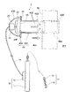
図1〜6には上記換気扇1の第1実施形態が示されており、図1は換気扇1の基本システム図、図2は換気扇1の全体概略図、図3は換気扇1を、例えば公団の建物の室内Rに取り付けた状態の正面図、図4は図3におけるIV-IV線に沿った縦断面図、図5は換気扇1の斜視図、図6は外気吸入ファン30の斜視図である。
Hereinafter, embodiments of a ventilation fan with a solar panel (hereinafter simply referred to as a ventilation fan) according to the present invention will be described with reference to the drawings.
1 to 6 show a first embodiment of the
まず、図1に基づいて換気扇1の基本システムを説明する。
上記換気扇1は、太陽光を採り入れて発電した電力を供給する発電部10と、この発電部10から供給された電力により換気を実施する換気扇本体部20とを備えて構成されている。
First, the basic system of the
The
発電部10は、太陽光を採り入れて発電するソーラーパネル11と、このソーラーパネル11により発電された電気を蓄電する蓄電器12と、発電部10と換気扇本体部20とを結ぶ回路15と、この回路15中に設けられた抵抗13と、図略のスイッチおよび光感知センサとを備えて構成されている。
The
換気扇本体部20は、ソーラーパネル11の発電により回転駆動するモータ21と、このモータ21の回転駆動により回転されるファン22と、これらのモータ21およびファン22を保持すると共に、建物の第1の被取り付け部位である引き戸サッシ50(図2,5,6参照)に着脱可能に装着する枠体23とを備えて構成されている。
The ventilation fan
ソーラーパネル11は、その大きさが、例えば、縦寸法が180〜190mm、横寸法が250〜260mm、厚さ寸法が15〜20mmに形成され、平面大きさが、紙の規格であるB4サイズとほぼ同じ大きさに形成されている。
このソーラーパネル11の出力はMAXで4.5W、電流はMAXで250mA、電流はMAXで18Vとなるように設定されている。しかし、通常時、つまり実際の使用時には、実験データからみると、上記それぞれの数値の70〜75%で運転されており、この状態で充分な効果を得ることができる。
The size of the
The output of the
モータ21は小型の直流ファンモータ21が使用されており、その大きさは、例えば80mm×80mm×厚さ25.5mmとなっている。そして、最大風量が0.73m3/min〜1.2m3/min、駆動電圧が8.4〜13.8V(直流)、駆動電流が80mAとなっている。
A small
ファン22の大きさは、後述する小窓部53(図5参照)の高さ寸法、例えば100〜120mmと略同じ寸法の直径に形成されている。ファン22は、電流が160mA、回転が2150mine、電力が1Wとなっている。
蓄電器12は、例えばリチウムイオン電池等で、充、放電可能な電池が用いられ、DC12V、容量1000mAh〜1600mAhのものが用いられている。
The size of the
The
前述のように、ソーラーパネル11の電流がMAXで250mA、蓄電器12が170mA、モータ21の駆動電流が80mAとしたとき、ソーラーパネル11(晴天時)により発電された電力18V、250mAでモータ21の80mAを駆動させながら蓄電器12に充電する。これを数式で表すと、250−80=170mAとなり、充電電流が170mAであることが理解できる。
As described above, when the current of the
又、容量1000mAhの蓄電器12を用いた場合にどの程度の時間でフル充電になるか計算すると、1000÷170≒5.9となり、日照時間内の5.9時間で充分に充電することが可能である。
In addition, when calculating how long it takes to fully charge when using the
充電途中で日陰になる等、太陽光発電が停止した場合、既に充電した蓄電器12により換気扇1を駆動させる。この場合、1000÷80=12.5となり、蓄電器12だけで12.5時間作動することになる。
When solar power generation stops, such as in the shade during charging, the
以上から、ソーラーパネル11の1日の発電稼動時間を算出する。ソーラーパネル11において最も効率よい発電が期待できる日照時間が、例えば7:00〜16:00までの9時間とした場合、この9時間に上記12.5時間を加えた約20時間稼動できることになる。この稼働時間では、確かに24時間フル稼働には到達しないが、この約20時間の稼動は、前述のような小型、軽量の換気扇1の能力としては充分な効果を得るものである。
From the above, the daily power generation operation time of the
次に、図2に基づいて前記換気扇1の構造を説明する。
換気扇1は、前記発電部10と前記換気扇本体部20とを備えている。
発電部10は、太陽光を採り入れて発電する前記ソーラーパネル11と、このソーラーパネル11の裏面に一体的に設けられ、ソーラーパネル11により発電された電気を蓄電する蓄電器12とを備えて構成されている。
Next, the structure of the
The
The
又、ソーラーパネル11の例えば上面にはパネル支持体17が設けられている。
このパネル支持体17は、ソーラーパネル11を太陽光の当たる所定位置に支持するものであり、一端がソーラーパネル11の上面に固着され、他方がフリーとなった紐状部材である例えば鎖18と、この鎖18の先端に設けられたフック部材19とで形成されている。
Further, a
The
鎖18は長さ調整可能となっており、又、フック部材19は、例えば鉤型に形成されている。その結果、ソーラーパネル11を太陽光Hが当たる所定の位置に配置する際、鉤型のフック部材19を第2の被取り付け部位(具体的には、後述するカーテンレール57)に引っ掛け、鎖18でソーラーパネル11を吊るした状態で配置することができる。
なお、紐状部材を、鎖18に換えてロープ等を用いてもよく、又、フック部材19は鉤型でなくてもよく、その位置に固定できる例えば洗濯ばさみ状のものでもよい。
The length of the
A rope or the like may be used instead of the
前記換気扇本体部20は、建物の第1の被取り付け部位である引き戸サッシ50に着脱可能に装着する枠体23を備えている。
この枠体23は、建物の引き戸サッシ50の上部に設けられている小窓部53(図5,6も参照)に挿入される本体部23Aと、前記モータ21およびファン22を支持するモータ支持部23Bと、建物の室内への風雨の侵入を防止するフード23Cとを備えて構成されている。
The ventilation fan
The
本体部23Aは、図3に詳細を示すように、矩形状のプレートで形成されており、その略中央部には、ファン22から送り込まれる空気を排出させる開口部23Dが形成されている。この開口部23Dは長方形となっている。
本体部23Aの短辺方向両端部は、所定幅寸法で長辺方向に沿った窓枠挿入部23Eとなっている。この窓枠挿入部23Eは、枠体23を、建物の被取り付け部位としての、例えば公共住宅に装備されている引き戸サッシ50の上部小窓部53に装着する際、小窓用枠部55の溝55Aに挿入できるようになっている。
又、開口部23Dには、外部から室内への虫の侵入を防止する防虫網24が張られている。
As shown in detail in FIG. 3, the
Both end portions in the short side direction of the
In addition, an
モータ支持部23Bは、本体部23Aの室内側表面に設けられている。このモータ支持部23Bは、前記ファン22を開口部23Dに対して適切な距離を保つように、又ファン22の回転の支障とならないような形状に形成されている。そして、軽量化を図るために、所定幅に形成された例えば4枚のプレート状部材を、図3に示すように、例えば襷掛け状に配置してモータ21を均等に支持するようになっている。
The
前記フード23Cは、雨や雪、強い風等が、開口部23Dから室内へ吹き込むのを防止するためのものであり、本体部23Aの前方側、つまり室外側に突出して形成されている。このフード23Cは、その投影面積が前記開口部23Dを覆える大きさに形成されており、側面断面が、なだらかな円弧状となって前方に突出した形状となっている。そして、フード23Cは、上部小窓部53のガラス小窓54を開けたとき、その開口空間を挿通できるようになっている。
The
以上の説明は、室内の空気を室外に排出する換気扇1の説明であったが、図4には、外気を室内に取り入れる外気吸入ファン30が示されている。
この外気吸入ファン30は、空室の状態が長期間に及ぶとき等、そして、特に夏の気温上昇時に、室内の温度が著しく上昇した場合等、換気扇1だけで室内空気を換気しても、室内の温度を下げることができないので、外気を吸入して換気し、よって室内の温度を下げようとするものである。
The above description is the description of the
The outside
図4に示すように、外気吸入ファン30は、矩形形状のプレートで形成された枠本体31と、この枠本体31の室外側表面に設けられたフード32とを備えて形成されている。枠本体31の略中央部には矩形形状の開口部31Aが形成されており、この開口部31Aには、防虫網33が張られている。又、枠本体31の短辺方向両端部は、所定幅寸法で長辺方向に沿った窓枠挿入部31Eとなっている。この窓枠挿入部31Eは、枠本体31を、前記引き戸サッシ50の上部小窓部53に装着する際、小窓用枠部55の溝55Aに挿入できるようになっている。
As shown in FIG. 4, the outside
図3,4からもわかるように、外気吸入ファン30は、前記換気扇1の枠体23の本体部23Aにフード23Cを設けた形状と、略同じ形状である。
そして、以上のような外気吸入ファン30も、前記換気扇1の枠体23と同様に、前記引き戸サッシ50A(図5参照)とは別の引き戸サッシ50Bの小窓部53に、容易に取り付け、取り外し可能に装着されるようになっている。
As can be seen from FIGS. 3 and 4, the outside
The outside
次に、図5,6に基づいて、以上のような換気扇1と外気吸入ファン30とを、例えば公共住宅の室内の引き戸サッシ50に取り付けた状態を説明する。
Next, based on FIGS. 5 and 6, a state in which the
まず、建物の室内Rの説明をする。
建物の室内Rには、外部との境界として引き戸サッシ50が例えば2枚、左右にスライド自在に設けられている。この引き戸サッシ50は、アルミ等で所定の規格寸法に形成された枠部材51と、この枠部材51に嵌め込まれた窓ガラス52を備えて形成されている。
又、引き戸サッシ50の上部には枠状に形成された小窓部53が設けられ、この小窓部53には、スライド開閉式のガラス小窓54が嵌め込まれている。ガラス小窓54は、上記小窓部53における小窓用枠部55の溝55A内に挿入され、その溝部55A内をスライドできるようになっている。
さらに、引き戸サッシ50の上方の建物の壁部56には、建物の第2被取り付け部位であるカーテンレール57が敷設されている。
First, the room R in the building will be described.
In the room R of the building, for example, two sliding
Further, a
Furthermore, a
前記換気扇1は、図5に示された2枚の引き戸サッシ50のうち、1枚の引き戸サッシ50Aの小窓部53と、カーテンレール57とにわたって取り付けられている。
すなわち、小窓部53のガラス小窓54を開けておいて、その開放空間に、換気扇1の枠体23の挿入部23Eを、その上下いずれか一方を先に前記溝部55Aに差し込み、他方の位置を調整しながら反対側を、反対側の溝部55Aに差し込んで枠体23が取り付けられている。この際、フード23Cは室外側に位置している。
枠体23の取り付けは、室内において、まず枠体23を両手に持った状態でフード23Cを、ガラス小窓54を開けた開放空間を挿通させておいて、上記のような動作で行われる。
The
That is, the glass
The attachment of the
これに対して、前記ソーラーパネル11は、その発電側面が太陽光を取り入れるガラス52に対向して配置されている。すなわち、ソーラーパネル11は、前記先端のフック部材19をカーテンレール57に引っ掛けた後、鎖18に吊るされた状態で設けられ、ソーラーパネル11が最適位置となるように、鎖18の長さが調整され、例えば枠部材51の上部のガラス54に対向している。
なお、ソーラーパネル11は鎖18に吊るされた状態であるが、蓄電器12も一体的に設けられていることから所定の重量があり、又、空室の室内は換気のための空気の流れがあるだけなので、ソーラーパネル11が不安定な状態となることはない。
On the other hand, the said
Although the
又、前記換気扇1が取り付けられた1枚の引き戸サッシ50Aに対して、例えば隣の室Rの引き戸サッシ50Bには、前記外気吸入ファン30が取り付けられている。
すなわち、外気吸入ファン30は引き戸サッシ50Bの小窓部53のガラス小窓54を開けた開放空間に設けられている。そして、モータ21等を含む換気扇本体部20が装着された引き戸サッシ50Aのある室Rと、外気吸入ファン30が装着された引き戸サッシ50Bのある室Rとは、建物の良好な室内換気のために、ドア等を開け放しておいた方がよい。
Further, for example, the outside
That is, the outside
外気吸入ファン30の取り付けに際しては、前述の枠体23の取り付けと略同様の手順で行われる。
そのため、室内Rには、外気吸入ファン30から外気が吸入され、その外気と室内の空気が混入した状態で、換気扇1によって室外に排出される。そして、この換気扇1の駆動は、窓ガラス52から入射される太陽光Hにより発電するソーラーパネル11からの電気によって行われる。
When the outside
Therefore, outside air is sucked into the room R from the outside
以上のような第1実施形態の換気扇1によれば、次のような効果が得られる。
(1)換気扇1が、発電部10と換気扇本体部20とを備えて構成され、発電部10がソーラーパネル11と蓄電器12とを有し、換気扇本体部20が、モータ21とファン22とこれらのモータ21およびファン22を保持する枠体23とで構成されているので、構造が簡単であり、かつ容易に持ち運びできると共に、自動的に空室の換気を行うことができる。
According to the
(1) The
(2)枠体23を介して換気扇本体部20を建物の第1の被取り付け部位である引き戸サッシ50に取り付け、発電部10を鎖18により、建物の第2の被取り付け部位であるカーテンレール57に支持させることで、換気扇1を取り付けることができる。取り外しも逆の手順により行え、取り外した後は別の所で使うことができ、これにより、カーテンレール57を利用して容易に取り付け、取り外しができると共に再利用が可能となる。
(2) The ventilation fan
(3)枠体23の挿入部23Eを引戸サッシ50の小窓用枠部55の溝55Aに挿入することで、換気扇本体部20を小窓部53に取り付けることができる。その結果、既存のものを利用して取り付けるので、換気扇1の取り付けるために新たに工事などしなくてもすみ、又、取り外した後も修復しなくてもすむ。特に、公営住宅等の建物では、引戸サッシ50の規格が統一されており、小窓部53も大きさが統一されていることから、1種類の換気扇本体部20、ひいては換気扇1を準備しておけばよいので、製作や管理が容易である。
(3) By inserting the
(4)枠体23に一体的に設けられたフード23が小窓部53を挿通可能な大きさに形成されているので、換気扇本体部20を室内側から取り付けることができる。その結果、取り付け工事に際して、例えば雨の日でも作業に何らの支障もなく行うことができ、決められた工期を守ることができる。
(4) Since the
(5)換気扇1の取り付けは、枠体23の挿入部23Eを、窓枠55の溝部55Aに挿入するだけで行えるので、誰でも取り付け工具なしで、容易に取り付け、取り外しができる。その結果、取り付け工事の作業性の向上を図ることができる。
(5) Since the
(6)発電部10の取り付けに際して、長さ調整可能な鎖18のフック部19を建物のカーテンレール57に引っ掛けて発電部10のソーラーパネル11を支持することができる。そのため、取り付け、取り外しが容易となり、又、鎖18が長さ調整可能となっているので、ソーラーパネル11を太陽光に対しての最適の位置に配置することができる。
(6) When the
(7)ソーラーパネル11を用いた換気扇1であり、この換気扇1は1日のほとんどが稼動している。稼働中は、換気により室内の空気が排出されるので、外部から虫等が換気扇本体部20を経由して室内に侵入することはできないが、取り付け、取り外し時等を含めて、例え、わずかな時間、換気扇の稼動が停止した場合でも、枠体23の開口部23に防虫網24が設けられているので、虫等が室内に侵入することはなくなり、その結果、不快な感じを抱くことはない。
(7) It is the
(8)ソーラーパネル11を用いた換気扇1であり、この換気扇1は1日のほとんどが稼動しているので、公営住宅等の空室、貸室、オフィス等の空室の換気を自動的に行うことができる。そのため、例えば、管理会社の担当者が定期的に部屋を見て回り、室内の換気をする等の管理が不要となり、その結果、人件費の削減が可能となる。
(8) It is a
(9)ソーラーパネル11を用いた換気扇1であり、この換気扇1は1日のほとんどが稼動しているので、普段使用しない部屋の換気(別荘等)、電源のない、又は空室でブレーカを落としている家庭、電源のないガレージ、倉庫の換気等にも用いることができ、その場合、それらの部屋の換気を行えるので、建物の老朽化を少しでも遅らせることができる。
(9) This is a
(10)ソーラーパネル11を用いた換気扇1であり、この換気扇1は蓄電器12を備えているので、家の電源をOFFにしても、又、日照が得られなくても、蓄電器12に充分に蓄電されている場合、蓄電器12だけで12.5時間作動させることができる。そのため、効率のよい換気が可能となる。
(10) A
(11)換気扇1のモータ21は、例えば80mm×80mm×厚さ25.5mmの小型の直流ファンモータであるが、最大風量が0.73m3/min〜1.2m3/minもあるので、小さくても大きな風量を得ることができ、効率のよい換気を行うことができる。
(11) the
次に、図7〜9に基づいて、本発明の換気扇1の第2実施形態を説明する。
なお、この第2実施形態において、前記第1実施形態の換気扇1の構造、および使用部材等と同じものには、同一符号を付すとともに、その詳細な説明は省略又は簡略化する。
Next, based on FIGS. 7-9, 2nd Embodiment of the
In addition, in this 2nd Embodiment, while the same code | symbol is attached | subjected to the same thing as the structure of the
本第2実施形態の換気扇2は、室内の空調設備用のダクト穴56Aがあけられている場合に、そのダクト穴56Aを被取り付け部としてそこに取り付けたものである。
すなわち、本第2実施形態は、室内に前記引き戸サッシ50が設けられておらず、あるいは引き戸サッシ50が設けられていてもその上部にガラス小窓がない場合に適用されるものである。
ここで、空調設備用のダクト穴56Aは、例えばφ45とφ100の大きさのもの、2種類が多く用いられている。
In the
That is, this 2nd Embodiment is applied when the said sliding
Here, two types of
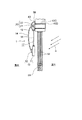
図7に示すように、本第2実施形態の換気扇2は、前記ソーラーパネル11と、このソーラーパネル11と一体的になった前記蓄電器12と、前記換気扇本体20と、この換気扇本体20が装着された枠体43と、前記ソーラーパネル11を太陽光の当たる所定位置に支持する前記パネル支持体17を備えている。
As shown in FIG. 7, the
本第2実施形態の換気扇2は、前述のように、室内の空調設備用のダクト穴56Aに枠体43を取り付けたものであり、従って、この枠体43の構造が、前記第1実施形態の換気扇1の枠体23と異なっているものである。
すなわち、枠体43は中央部が丸状の開口部43Fとなったドーナツ形状に形成された枠本体43Aと、この枠本体43Aに設けられたモータ支持部43Bと、枠本体43Aの前方、つまりモータ支持部43Bとは反対側に枠本体43Aと一体的に形成された挿入部43Cとを含み形成されている。
As described above, the
That is, the
挿入部43Cは丸パイプ状に形成され、その外形寸法は、前記空調設備用のダクト穴56Aの直径と略同じ大きさになっている。又、挿入部43Cの先端には、外周外側に突出した断面略釣り針状の係止部43Dが形成されている。
そして、この係止部43Dは、挿入部43Cおよび枠本体43Aの抜け止め用であり、枠体43をダクト穴56Aに装着したとき、図7に仮想線で示すように、ダクト穴56Aの室外側端部で拡開し、これにより、挿入部43C、ひいては枠体43がダクト穴56Aから抜けないようになっている。
The
The locking
さらに、挿入部43Cの先端側には、先端から枠本体43A側に所定寸法後退した位置まで複数のスリット43Eが形成されている。これらのスリット43Eは、挿入部43Cの長手方向に沿って形成されている。
これにより、係止部43Dの外径がダクト穴56Aの直径よりも大きく形成されていても、挿入部43Cをダクト穴56Aに挿入すると、スリット43Eの部位で挿入部43Cが縮小されるため、図7に仮想線で示すようにダクト穴56Aに押し込むことができ、挿入部43Cが完全に挿入されたとき、スリット43Eが元の状態に戻り、つまり拡開し、先端の係止部43Dが前述のように抜け止めとなる。
Further, a plurality of
Thereby, even if the outer diameter of the locking
なお、枠本体43Aの壁56側表面に、例えばスポンジで形成されたパッキン44を貼り付けてもよく、このようにすれば、枠体43をダクト穴56Aに装着した載、壁56の塗装等を傷めることがない。
又、枠本体43Aの開口部43Fには、防虫網45が設けられている。
Note that a packing 44 made of, for example, sponge may be attached to the surface of the frame
An
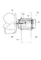
図8,9には、以上のような構成の換気扇2を取り付けた状態が示されている。
これらの図8,9に示すように、換気扇2の枠体43が、室R内に既に形成されている空調設備用のダクト穴56Aに装着されており、換気扇2のソーラーパネル11が、フック部材19をカーテンレール57に引っ掛けて鎖18で支持され、パネル11表面が太陽光Hに当たるように窓ガラス52に対向して所定位置に配置されている。
8 and 9 show a state where the
As shown in FIGS. 8 and 9, the
以上のような第2実施形態によれば、前記(1)、(4)、(6)〜(11)と略同様の効果を得ることができると共に、次に示すような効果を得ることができる。
(12)枠体43の挿入部43Cを建物の室内空調用のダクト穴56Aに挿入することで、換気扇本体部20を取り付けることができる。その結果、既存のものを利用して取り付けるので、換気扇2の取り付けるために新たに工事などしなくてもすみ、又、取り外した後も修復しなくてもすむ。特に、一般的なダクト穴56Aの大きさがφ45とφ100との2種類の大きさに統一されていることから、2種類の換気扇本体部20、ひいては換気扇2を準備しておけばよいので、製作や管理が容易である。
According to the second embodiment as described above, substantially the same effects as the above (1), (4), and (6) to (11) can be obtained, and the following effects can be obtained. it can.
(12) The ventilation fan
(13)枠体43の挿入部43Cの先端にダクト穴56Aの直径より大きな径の先端抜止め部43Dが形成されており、枠体43の挿入部43Cがダクト穴56Aに挿入され、かつ貫通したとき、先端抜止め43Dが拡開してダクト穴56Aの端部に係止可能となるので、枠体43を建物に確実に固定することができ、換気扇2の稼動時に、換気扇本体部20が不安定な状態になったり、落下したりすることがなく、これにより、換気扇2の安全な運転が保障される。
(13) A
なお、本発明は前述の各実施形態に限定されるものではなく、本発明の目的を達成できる範囲での変形、改良等は本発明に含まれるものである。 The present invention is not limited to the above-described embodiments, and modifications, improvements, and the like within the scope that can achieve the object of the present invention are included in the present invention.
例えば、前記第1実施形態では、換気扇1を建物の室内の引き戸サッシ50に取り付けたが、換気扇1の取り付け位置は室内に限らない。図10に示すように、換気扇1を建物の屋根の軒下と引き戸サッシ50とにわたって設け、屋根裏換気を行うようにしてもよい。
すなわち、換気扇1の換気扇本体部20を軒下の板部材60に、前記引き戸サッシ50のガラス小窓53の大きさよりわずかに小さな矩形状の開口部60Aを形成し、この開口部60Aを覆うようにして、換気扇1の枠体23が図略の固定具を介して取り付けられている。この際、換気扇本体部20が屋根裏側に位置し、フード23Cは屋根裏外に突出している状態となっている。
又、ソーラーパネル11は、前記フック部材19および鎖18を介して、前記引き戸サッシ50の上方のカーテンレール57に吊るされて支持されている。
そして、このような変形形態では、建物の空室の屋根裏換気を、自動的に、かつ毎日ほぼ20時間にわたって行えるので、空室の室内のみならず、屋根裏の換気を行うことができ、これにより、空室を良好な状態に維持することができる。
For example, in the said 1st Embodiment, although the
That is, a
The
And in such a variant, the attic ventilation of the vacancies in the building can be performed automatically and for almost 20 hours every day, so that not only the interior of the vacancies but also the attic can be ventilated, The vacancy can be maintained in a good state.
又、換気扇1Aを、図11に示すように、建物の床下と床面上にわたって設けてもよい。すなわち、この変形形態では、換気扇1を構成するパネル支持体17Aが、ソーラーパネル11の両側面を保持する3本の脚部材70で構成されており、これにより、ソーラーパネル11を含む発電部10を床面71上に載置することができる。なお、脚部材70は折り畳み可能となっており、又、ソーラーパネル11の太陽光Hに対する傾き角度を調整することができるようになっている。
換気扇本体部20は、その枠体23が基礎72の内側面に、例えばコンクリート用釘で取り付けられている。
なお、基礎72に予め形成されている小動物侵入防止用の開口72Aが、上記枠体2323より大きい場合は、当該枠体23を開口72Aより大きく形成すればよい。
そして、このような変形形態では、建物の床下の換気を、自動的に、かつ毎日ほぼ20時間にわたって行えるので、床下からの湿気による影響を少しでも排除することができ、これにより、空室を良好な状態に維持することができる。
Moreover, you may provide 1 A of ventilation fans over the floor under a building and a floor surface, as shown in FIG. That is, in this modified embodiment, the
The
When the
And in such a variant, the underfloor ventilation of the building can be carried out automatically and for almost 20 hours every day, so that the influence of moisture from under the floor can be eliminated as much as possible, It can be maintained in a good state.
更に、前記第1実施形態では、換気扇1を1つの部屋の引き戸サッシ50Aの一方に設け、隣り合う室内の引き戸サッシ50Bの一方に外気吸気ファン30を設けた構成としたが、これに限らない。
引き戸サッシ50の両方に小窓部が形成されている場合に、それらの引き戸サッシ50の互いに最も遠い位置の小窓部に、換気扇1と外気吸気ファン30とを設け、1つの部屋の換気と外気吸気とを行うようにしてもよい。そして、各室を同じような構成としてもよい。このようにすれば、空室のより一層の換気効果を得ることができ、空室をより良好な状態に維持することができる。
Furthermore, in the said 1st Embodiment, although it was set as the structure which provided the
When the small window portions are formed in both of the sliding
又、前記第1実施形態では、換気扇1を1つの部屋の引き戸サッシ50の一方に設け、前記第2実施形態では、換気扇2を1つの部屋の空調機用のダクト穴56Aと引き戸サッシ50とにわたって設けた構成としたが、これに限らない。
引き戸サッシ50がある部屋と引き戸サッシ50の他にダクト穴56Aもある部屋では、1つの部屋の引き戸サッシ50に換気扇1を設けると共に、1つの部屋でダクト穴56Aを利用して設けてもよい。
Moreover, in the said 1st Embodiment, the
In the room with the sliding
本発明は、公営住宅等の空室、貸室、オフィスの空室、日常的に使われない別荘等の部屋、電源のないガレージ、倉庫等の管理を行う際に利用できる。 INDUSTRIAL APPLICABILITY The present invention can be used when managing a vacant room such as a public housing, a rental room, an office vacant room, a room such as a villa not used on a daily basis, a garage without a power source, and a warehouse.
1,2 ソーラーパネル付換気扇
10 発電部
11 ソーラーパネル
12 蓄電器
13 抵抗
17 パネル支持体
18 紐状部材である鎖
19 フック部材
20 換気扇本体部
21 モータ
22 ファン
23 枠体
23A 本体部
23B モータ支持部
23C フード部
23D 開口部
23E 挿入部
30 外気吸入ファン
50 引き戸サッシ
52 窓ガラス
53 小窓部
55 小窓部用枠
55A 第1被取り付け部位である溝部
54 ガラス小窓
57 第2被取り付け部位であるカーテンレール
DESCRIPTION OF
Claims (10)
太陽光を採り入れて発電した電力を供給する発電部と、
この発電部から供給された電力により換気を実施する換気扇本体部とを備えて構成し、
前記発電部を、太陽光を採り入れて発電するソーラーパネルと、このソーラーパネルにより発電された電気を蓄電する蓄電器とを有する構成とし、
前記換気扇本体部を、前記ソーラーパネルの発電により回転駆動するモータと、このモータの回転駆動により回転されるファンと、これらのモータおよびファンを保持すると共に前記建物の第1の被取り付け部位に着脱可能に装着する枠体とを備えた構成とし、
前記発電部を支持するパネル支持体により、前記ソーラーパネルを太陽光が当たる位置となるように前記建物の第2の被取り付け部位に支持したことを特徴とするソーラーパネル付換気扇。 In the ventilation fan with solar panel that ventilates the inside of the building,
A power generation unit that supplies power generated by taking in sunlight; and
It comprises a ventilation fan body that implements ventilation with the power supplied from this power generation unit,
The power generation unit is configured to have a solar panel that takes in sunlight to generate electricity, and a capacitor that stores electricity generated by the solar panel,
A motor that rotationally drives the ventilation fan main body by power generation of the solar panel, a fan that is rotated by the rotational drive of the motor, and holds and removes the motor and the fan from the first attachment site of the building With a frame body that can be mounted,
A solar fan with a solar panel, wherein the solar panel is supported by a second attachment site of the building so that the solar panel is in a position where it is exposed to sunlight by a panel support that supports the power generation unit.
前記本体部に、前記ファンから送り込まれる空気を排出させる開口部を形成すると共に、前記小窓部の前記ガラス小窓がスライド自在にはめ込まれる前記第1の被取り付け部位に挿入する挿入部を有する構成としたことを特徴とする請求項1に記載のソーラーパネル付換気扇。 Used in a sliding door sash having a frame-like small window portion in which a glass small window is slidable in the room of the building, the frame body, a main body portion inserted into the small window portion, the motor and the fan. Comprising a motor support part to support, and a hood that prevents intrusion of wind and rain into the building interior;
An opening for discharging air sent from the fan is formed in the main body, and an insertion portion is inserted into the first attachment site into which the glass small window of the small window is slidably fitted. It was set as the structure, The ventilation fan with a solar panel of Claim 1 characterized by the above-mentioned.
Priority Applications (1)
| Application Number | Priority Date | Filing Date | Title |
|---|---|---|---|
| JP2007279547A JP5112817B2 (en) | 2007-10-26 | 2007-10-26 | Exhaust fan with solar panel |
Applications Claiming Priority (1)
| Application Number | Priority Date | Filing Date | Title |
|---|---|---|---|
| JP2007279547A JP5112817B2 (en) | 2007-10-26 | 2007-10-26 | Exhaust fan with solar panel |
Publications (2)
| Publication Number | Publication Date |
|---|---|
| JP2009109043A true JP2009109043A (en) | 2009-05-21 |
| JP5112817B2 JP5112817B2 (en) | 2013-01-09 |
Family
ID=40777714
Family Applications (1)
| Application Number | Title | Priority Date | Filing Date |
|---|---|---|---|
| JP2007279547A Active JP5112817B2 (en) | 2007-10-26 | 2007-10-26 | Exhaust fan with solar panel |
Country Status (1)
| Country | Link |
|---|---|
| JP (1) | JP5112817B2 (en) |
Cited By (2)
| Publication number | Priority date | Publication date | Assignee | Title |
|---|---|---|---|---|
| JP5618992B2 (en) * | 2009-04-16 | 2014-11-05 | 立川ブラインド工業株式会社 | Electric blind solar panel mounting device |
| JP2015090234A (en) * | 2013-11-05 | 2015-05-11 | フジモリ産業株式会社 | Indoor ventilation method and device therefor |
Citations (13)
| Publication number | Priority date | Publication date | Assignee | Title |
|---|---|---|---|---|
| JPS55128892U (en) * | 1979-03-08 | 1980-09-11 | ||
| JPS573923U (en) * | 1980-06-09 | 1982-01-09 | ||
| JPS57124045U (en) * | 1981-01-27 | 1982-08-02 | ||
| JPS58148524U (en) * | 1982-03-31 | 1983-10-05 | 三菱電機株式会社 | Window frame for installing ventilation fan |
| JPS6156487U (en) * | 1984-09-18 | 1986-04-16 | ||
| JPS61130835U (en) * | 1985-01-30 | 1986-08-15 | ||
| JPS61190228A (en) * | 1985-02-16 | 1986-08-23 | Nippon Paruko Solar Kk | Ventilating method of vacant house |
| JPH09119688A (en) * | 1995-10-26 | 1997-05-06 | Tsuneo Obata | Ventilating fan for small sash window |
| JPH11108412A (en) * | 1997-10-07 | 1999-04-23 | Cosmo Denki Kk | Ventilation fan unit, underfloor ventilation device, underfloor ventilation system, and underfloor ventilation system control device |
| JP2000046398A (en) * | 1998-07-29 | 2000-02-18 | Taisei Corp | Garret ventilating system |
| JP2001349154A (en) * | 2000-06-12 | 2001-12-21 | Fujisash Co | Double sliding sash |
| JP2002134776A (en) * | 2000-10-30 | 2002-05-10 | Canon Inc | Solar cell module and its installation method |
| JP2008256274A (en) * | 2007-04-05 | 2008-10-23 | Seiwa Metal:Kk | Energy-saving ventilating and deodorizing device for vacant house and vacant room in apartment house |
-
2007
- 2007-10-26 JP JP2007279547A patent/JP5112817B2/en active Active
Patent Citations (13)
| Publication number | Priority date | Publication date | Assignee | Title |
|---|---|---|---|---|
| JPS55128892U (en) * | 1979-03-08 | 1980-09-11 | ||
| JPS573923U (en) * | 1980-06-09 | 1982-01-09 | ||
| JPS57124045U (en) * | 1981-01-27 | 1982-08-02 | ||
| JPS58148524U (en) * | 1982-03-31 | 1983-10-05 | 三菱電機株式会社 | Window frame for installing ventilation fan |
| JPS6156487U (en) * | 1984-09-18 | 1986-04-16 | ||
| JPS61130835U (en) * | 1985-01-30 | 1986-08-15 | ||
| JPS61190228A (en) * | 1985-02-16 | 1986-08-23 | Nippon Paruko Solar Kk | Ventilating method of vacant house |
| JPH09119688A (en) * | 1995-10-26 | 1997-05-06 | Tsuneo Obata | Ventilating fan for small sash window |
| JPH11108412A (en) * | 1997-10-07 | 1999-04-23 | Cosmo Denki Kk | Ventilation fan unit, underfloor ventilation device, underfloor ventilation system, and underfloor ventilation system control device |
| JP2000046398A (en) * | 1998-07-29 | 2000-02-18 | Taisei Corp | Garret ventilating system |
| JP2001349154A (en) * | 2000-06-12 | 2001-12-21 | Fujisash Co | Double sliding sash |
| JP2002134776A (en) * | 2000-10-30 | 2002-05-10 | Canon Inc | Solar cell module and its installation method |
| JP2008256274A (en) * | 2007-04-05 | 2008-10-23 | Seiwa Metal:Kk | Energy-saving ventilating and deodorizing device for vacant house and vacant room in apartment house |
Cited By (2)
| Publication number | Priority date | Publication date | Assignee | Title |
|---|---|---|---|---|
| JP5618992B2 (en) * | 2009-04-16 | 2014-11-05 | 立川ブラインド工業株式会社 | Electric blind solar panel mounting device |
| JP2015090234A (en) * | 2013-11-05 | 2015-05-11 | フジモリ産業株式会社 | Indoor ventilation method and device therefor |
Also Published As
| Publication number | Publication date |
|---|---|
| JP5112817B2 (en) | 2013-01-09 |
Similar Documents
| Publication | Publication Date | Title |
|---|---|---|
| JP2007120861A (en) | Ventilation/temperature conditioning control device and method | |
| JP2011021833A (en) | Building frame interior ventilation system | |
| JP5112817B2 (en) | Exhaust fan with solar panel | |
| JP2007138693A (en) | Building with skylight window | |
| KR100685291B1 (en) | Ventilation fan | |
| JP5878135B2 (en) | Air conditioning structure of buildings | |
| KR100588073B1 (en) | Board of rainwater interception | |
| JP6184095B2 (en) | Intermediate area creation structure inside and outside the house | |
| KR100628982B1 (en) | a Windows and Doors have the Faculty of Automatic Ventilation | |
| KR200374308Y1 (en) | a Windows and Doors have the Faculty of Automatic Ventilation | |
| JPH11148693A (en) | Ventilation structure for house | |
| JP4516090B2 (en) | Energy-saving ventilation and odor removal equipment for vacant houses and vacant spaces in apartment buildings | |
| KR100635267B1 (en) | Board of rainwater interception | |
| JP2007132153A (en) | Building | |
| KR101521196B1 (en) | Ventilating system for construction | |
| KR20100008157U (en) | Board for Interception of Rainfall | |
| JP2002013359A (en) | Fitting for natural ventilation | |
| JP3085719U (en) | Gully with solar cell panel and ventilation device using the same | |
| JP2007182691A (en) | Building | |
| CN218029959U (en) | Automatic door and window ventilation device | |
| CN217950211U (en) | Novel energy-concerving and environment-protective aluminum-wood window | |
| CN215062545U (en) | Green constant temperature building | |
| CN214657676U (en) | Safety air conditioner position structure | |
| JP2000297497A (en) | External wall body | |
| JPH07102791A (en) | Building and remodeling method for building |
Legal Events
| Date | Code | Title | Description |
|---|---|---|---|
| A621 | Written request for application examination |
Free format text: JAPANESE INTERMEDIATE CODE: A621 Effective date: 20101014 |
|
| A977 | Report on retrieval |
Free format text: JAPANESE INTERMEDIATE CODE: A971007 Effective date: 20120120 |
|
| A131 | Notification of reasons for refusal |
Free format text: JAPANESE INTERMEDIATE CODE: A131 Effective date: 20120214 |
|
| A521 | Request for written amendment filed |
Free format text: JAPANESE INTERMEDIATE CODE: A523 Effective date: 20120412 |
|
| TRDD | Decision of grant or rejection written | ||
| A01 | Written decision to grant a patent or to grant a registration (utility model) |
Free format text: JAPANESE INTERMEDIATE CODE: A01 Effective date: 20120918 |
|
| A01 | Written decision to grant a patent or to grant a registration (utility model) |
Free format text: JAPANESE INTERMEDIATE CODE: A01 |
|
| A61 | First payment of annual fees (during grant procedure) |
Free format text: JAPANESE INTERMEDIATE CODE: A61 Effective date: 20121011 |
|
| FPAY | Renewal fee payment (event date is renewal date of database) |
Free format text: PAYMENT UNTIL: 20151019 Year of fee payment: 3 |
|
| R150 | Certificate of patent or registration of utility model |
Ref document number: 5112817 Country of ref document: JP Free format text: JAPANESE INTERMEDIATE CODE: R150 Free format text: JAPANESE INTERMEDIATE CODE: R150 |
|
| R250 | Receipt of annual fees |
Free format text: JAPANESE INTERMEDIATE CODE: R250 |
|
| R250 | Receipt of annual fees |
Free format text: JAPANESE INTERMEDIATE CODE: R250 |
|
| R250 | Receipt of annual fees |
Free format text: JAPANESE INTERMEDIATE CODE: R250 |
|
| R250 | Receipt of annual fees |
Free format text: JAPANESE INTERMEDIATE CODE: R250 |
|
| R250 | Receipt of annual fees |
Free format text: JAPANESE INTERMEDIATE CODE: R250 |
|
| R250 | Receipt of annual fees |
Free format text: JAPANESE INTERMEDIATE CODE: R250 |