JP2009108562A - Self-standing indicator - Google Patents
Self-standing indicator Download PDFInfo
- Publication number
- JP2009108562A JP2009108562A JP2007281078A JP2007281078A JP2009108562A JP 2009108562 A JP2009108562 A JP 2009108562A JP 2007281078 A JP2007281078 A JP 2007281078A JP 2007281078 A JP2007281078 A JP 2007281078A JP 2009108562 A JP2009108562 A JP 2009108562A
- Authority
- JP
- Japan
- Prior art keywords
- self
- pipe
- insertion pipe
- lock
- support leg
- Prior art date
- Legal status (The legal status is an assumption and is not a legal conclusion. Google has not performed a legal analysis and makes no representation as to the accuracy of the status listed.)
- Granted
Links
Images


Landscapes
- Road Signs Or Road Markings (AREA)
Abstract
Description
本発明は、災害地域や汚染地域などの危険地域に旗などの標識を自立式に立てることができる自立式標示器に関する。 The present invention relates to a self-supporting sign that can stand a sign such as a flag in a self-supporting manner in a danger area such as a disaster area or a contaminated area.
従来、例えば汚染地域に旗竿を立てて標示するものがあった。旗竿は遠隔操作で立てるようになっており、例えば走行車両に搭載したマニプレータにより地面に突き刺して立てるようになっている(例えば、特許文献1参照)。 Conventionally, for example, there has been a case where a flag pole is set and marked in a contaminated area. The flagpole is set up by remote control. For example, the flagpole is set up by piercing the ground with a manipulator mounted on a traveling vehicle (see, for example, Patent Document 1).
しかしながら、従来の旗竿は地面に突き刺して立てる方式であるため、アスファルトなどの舗装道路などでは使用できなかった。 However, since the conventional flagpole is stabbed on the ground, it cannot be used on paved roads such as asphalt.
本発明は、竿の先端を地面などに押し付けるだけで、アスファルトなどの舗装道路などにも容易に立てることができる自立式標示器を提供することを目的とする。 An object of the present invention is to provide a self-supporting sign that can be easily set on a paved road such as asphalt simply by pressing the tip of the ridge against the ground or the like.
本発明に係る自立式標示器は、竿本体と、この竿本体内に挿入され、バネによって上昇方向に付勢された内挿パイプと、この内挿パイプ内に摺動自在に挿入され、上下に設けられた第1及び第2のロック手段を作動させるスイッチ軸と、前記内挿パイプに沿って上向きに折り畳まれ、前記スイッチ軸の上昇によって展張する支持脚とを少なくとも備えたことを特徴とする。 The self-supporting indicator according to the present invention includes a heel body, an insertion pipe inserted into the heel body and biased upward by a spring, and slidably inserted into the insertion pipe. At least a switch shaft for operating the first and second locking means provided on the support pipe, and a support leg that is folded upward along the insertion pipe and that is expanded by raising the switch shaft. To do.
本発明の自立式標示器では、スイッチ軸が地面に押し付けられると上昇し、第1のロック手段のロックが解除されるため、バネの力によって内挿パイプが竿本体内を上昇する。このため、上向きに折り畳まれた支持脚が展張して竿本体を自立させることができる。
したがって、アスファルトなどの舗装道路などにも容易に立てることができる。
In the self-supporting indicator of the present invention, when the switch shaft is pressed against the ground, the switch shaft is lifted and the lock of the first locking means is released, so that the insertion pipe is lifted in the bag main body by the force of the spring. For this reason, the support leg folded upward can be extended and the heel body can be made independent.
Therefore, it can be easily set up on a paved road such as asphalt.
また、前記竿本体は、この竿本体に沿って上向きに折り畳まれ、前記バネの力による前記内挿パイプの上昇によってロックが解除され、旗を展張させる旗展張用レバーをさらに備えたものである。
内挿パイプのバネの力による上昇力を利用することで、上向きに折り畳まれた旗展張用レバーを展張させることができる。これにより旗が展張するので、地震、土砂崩れなどの災害地域や、汚染地域、交通事故現場などに標識としての旗を簡単に立てることができる。
Further, the eaves body is further provided with a flag extending lever that is folded upward along the eaves body, unlocked by the rise of the insertion pipe by the force of the spring, and extended the flag. .
By using the lifting force generated by the spring force of the insertion pipe, the flag extending lever folded upward can be extended. As a result, the flag is expanded, so it is possible to easily set a flag as a sign in disaster areas such as earthquakes and landslides, contaminated areas, traffic accident sites, and the like.
また、前記第1及び第2のロック手段は、同一形状のロックレバーを備え、両ロックレバーが上下逆向きに配設された構成とするものである。
同一形状のロックレバーを上下逆向きに配設することにより、支持脚の折り畳み状態の固定と展張時の開脚位置の規制とを簡単なロック機構で構成することができる。
In addition, the first and second lock means are provided with lock levers having the same shape, and both lock levers are disposed upside down.
By arranging the lock lever of the same shape in the upside down direction, it is possible to configure the support leg in the folded state and the restriction of the position of the open leg at the time of expansion with a simple lock mechanism.
また、前記内挿パイプは、前記支持脚の基端部を枢着するハブを備え、前記竿本体は、前記支持脚の脚先部を着脱可能に係合する脚ホルダーパイプを備え、前記脚ホルダーパイプには前記支持脚の折りたたみ状態を保持するための前記第1のロック手段のロックレバーが出没するスリット穴が設けられ、前記内挿パイプには前記ハブの上昇位置を規制するための前記第2のロック手段のロックレバーが出没するスリット穴が設けられている構成とするものである。
これにより、第1のロック手段のロックレバーにより、支持脚の折り畳み状態を保持し、第2のロック手段のロックレバーにより、展張時の開脚位置の規制をすることができる。
The insertion pipe includes a hub that pivotally attaches a base end portion of the support leg, and the heel body includes a leg holder pipe that removably engages a leg tip portion of the support leg. The holder pipe is provided with a slit hole in which the lock lever of the first locking means for holding the folded state of the support leg is provided, and the insertion pipe is provided with the slit for restricting the raised position of the hub. A slit hole is provided in which the lock lever of the second lock means is projected and retracted.
Thereby, the folding state of the support leg can be held by the lock lever of the first lock means, and the position of the open leg at the time of expansion can be regulated by the lock lever of the second lock means.
また、前記支持脚は、可撓性の高い樹脂材料により構成されているものである。
これにより、本自立式標示器をある程度の高さから垂直に落とした場合でも、支持脚が反動を吸収できるため、不安定な地面等でも転倒させずに自立させることができる。
The support legs are made of a highly flexible resin material.
As a result, even when the self-supporting indicator is dropped vertically from a certain height, the support leg can absorb the reaction, so that it can stand on the unstable ground without falling down.
以下、本発明の一実施形態に係る自立式標示器について、図1〜図7を参照して説明する。ここでは、本発明を旗竿に適用した例を示すが、本発明はこれに限定されるものではない。
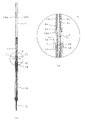
図1は本発明の自立式標示器の立面図(a)と断面図(b)、図2は旗竿収納状態における自立式標示器の全体断面図(a)、A部拡大断面図(b)、B部拡大断面図(c)及びC−C拡大断面図(d)、図3はスイッチ軸作動時の自立式標示器の全体断面図(a)、A部拡大断面図(b)及びB部拡大断面図(c)、図4は支持脚展張開始時の自立式標示器の全体断面図(a)及びA部拡大断面図(b)、図5は支持脚展張途中の自立式標示器の動作説明図、図6は支持脚及び旗展張時の自立式標示器の動作説明図、図7は自立式標示器の自立状態を示す外観図である。
Hereinafter, a self-supporting sign according to an embodiment of the present invention will be described with reference to FIGS. Here, although the example which applied this invention to the flagpole is shown, this invention is not limited to this.
FIG. 1 is an elevational view (a) and a sectional view (b) of a self-supporting sign according to the present invention, and FIG. 2 is an overall cross-sectional view (a) of the self-supporting sign in a state where a flag pole is stored, ), B part enlarged sectional view (c) and CC enlarged sectional view (d), FIG. 3 is an overall sectional view (a), A part enlarged sectional view (b) of the self-supporting indicator when the switch shaft is operated, Part B enlarged cross-sectional view (c), FIG. 4 is an overall cross-sectional view (a) and part A enlarged cross-sectional view (b) of FIG. FIG. 6 is a diagram illustrating the operation of the self-supporting sign when the support leg and the flag are extended, and FIG. 7 is an external view showing the self-supporting state of the self-supporting sign.
本例の自立式標示器としての旗竿は、中空パイプからなる竿本体1と、竿本体1内に挿入され、バネ4によって上昇方向に付勢された内挿パイプ2と、内挿パイプ2内に摺動自在に挿入され、上下に設けられた第1及び第2のロック手段である第1及び第2のロックレバー5、6を作動させるスイッチ軸3と、内挿パイプ2に沿って上向きに折り畳まれ、スイッチ軸3の上昇によって展張する支持脚7及び旗展張用レバー8とを備えている。
A flag pole as a self-supporting indicator of this example includes a hook
竿本体1は、複数のパイプ部分、例えば竿頭部11、旗ホルダーパイプ12、13、及び脚ホルダーパイプ14をそれぞれネジで結合した構成となっている。このうち下部の旗ホルダーパイプ13には枢軸15により旗展張用レバー8の基端部が枢着され、旗展張用レバー8の上部には旗ホルダーパイプ12と着脱可能なレバーホルダー16が取り付けられている。これによって、収納時、旗展張用レバー8は図1に示すように竿本体1とほぼ平行に折り畳まれるようになっている。旗30は、図7に示すように、竿頭部11に設けられた止め具17aと旗展張用レバー8の上下部に設けられた止め具17b、17cに巻き掛けられた紐18によって三角旗として展張するようになっている。また、旗展張用レバー8の基端部の枢着部材19と竿頭部11の止め具17aは、竿本体1を中心に回転自在に取り付けられている。
The
内挿パイプ2は、竿本体1に摺動自在に挿入され、内挿パイプ2の上部取付部材と脚ホルダーパイプ14の上端との間には、内挿パイプ2を上昇方向に付勢するバネ4が装着されている。さらに、内挿パイプ2の下部には複数本(本例では4本)の支持脚7の基端部を枢着するハブ20が取り付けられており、脚ホルダーパイプ14の外周部には図2のC−C断面図に示すように、支持脚7の脚先部7bを着脱可能に保持する脚ホルダー21が設けられている。さらに脚ホルダーパイプ14の下部には各支持脚7と一端がリンク結合された脚支えリンク7aの他端が枢着されている。これにより、各々の支持脚7と脚支えリンク7aは内挿パイプ2に沿って上向きに折り畳まれる。また、支持脚7はグラスファイバー入りの樹脂などの高い可撓性を有する樹脂材料で構成することにより、着地時の反動を吸収できるため、竿本体1を転倒しにくくすることができる。
The
スイッチ軸3は、内挿パイプ2内に摺動自在に挿入されており、上部に第1のロックレバー5が、下部に第2のロックレバー6が設けられている。第1及び第2のロックレバー5、6は、図2に示すように、同一形状のものからなり、これらを上下逆向きにスイッチ軸3に装着されている。すなわち、第1のロックレバー5は、ロック部5aが脚ホルダーパイプ14及び内挿パイプ2にそれぞれ設けられた上スリット穴14a、2aを通して出没可能に設けられており、第1のロックレバー5の基端部5b(但し、A部の拡大断面図では図示省略)は内挿パイプ2に設けられた穴に係合している。第2のロックレバー6も、第1のロックレバー5と上下逆向きに配設される点以外は同様の構成であり、ロック部6aが内挿パイプ2に設けられた下スリット穴2bを通して出没自在に設けられており、第2のロックレバー6の基端部6bは内挿パイプ2に設けられた穴に係合している。また、第1及び第2のロックレバー5、6のロック動作及びロック解除動作を可能にするべく、スイッチ軸3のパイプ壁には複数のスリット穴3a、3b、3cが対向状に及び上下反対に配設されている。すなわち、上下のスリット穴3aは、上記の上スリット穴14a、2a及び下スリット穴2bにそれぞれ向かい合って開口されており、スリット穴3bはスリット穴3aの下方または上方に開口されており、またスリット穴3cはスリット穴3a、3bと反対側のパイプ壁にもっとも長い穴で開口されている。
The
次に、本例の旗竿の使用方法及び動作について説明する。
(1)収納時
図1に示すように、支持脚7及び旗展張用レバー8はそれぞれ竿本体1に沿って上向きに折り畳まれる。このときには、第1のロックレバー5のロック部5aは、図2に示すように、上スリット穴14a、2a、3aより外方へ突出して内挿パイプ2を保持している。また、第2のロックレバー6のロック部6aは、下スリット穴2b、3bより外方へ突出してスイッチ軸3を保持している。支持脚7の脚先部7bは脚ホルダー21の切欠き部21aに係合して保持される。また、旗展張用レバー8はこのレバー8に取り付けられたC字状のレバーホルダー16が旗ホルダーパイプ12に係合して保持される。なお、C字状のレバーホルダー16が着脱可能に係合する旗ホルダーパイプ12の部分には角形などの窓12aが設けられており、レバーホルダー16を外すための舌状突起部16aが窓12aより旗ホルダーパイプ12内に進入するようになっている。
このように、旗竿を細径に折り畳んで収納できるため、例えば収納ケース内のターレット板(図示せず)に複数本(10本程度)収納することができる。
Next, the usage method and operation | movement of the flagpole of this example are demonstrated.
(1) During Storage As shown in FIG. 1, the
Thus, since the flagpole can be folded and stored in a small diameter, for example, a plurality (about 10) can be stored in a turret plate (not shown) in the storage case.
(2)スイッチ軸の作動時
この旗竿を、例えば走行車両に搭載したマニプレータにより竿頭部11を把持してスイッチ軸3の先端を地面に押し付けるか、あるいはある高さから垂直に落下させる。そうすると、スイッチ軸3の先端が接地することにより、スイッチ軸3が内挿パイプ2内をスライドして上昇する。これにより、図3に示すように、第1のロックレバー5のロック部5aはスイッチ軸3の上スリット穴3aの上端により押されて内部に引き込まれ、ロックが解除される。一方、第2のロックレバー6のロック部6aはスイッチ軸3の下スリット穴3aの上端により外部に押し出される。このため、第1のロックレバー5のロックが解除されるため、バネ4の力により内挿パイプ2は竿本体1内を上昇する。その結果、図4に示すように、支持脚7の脚先部7bが上方へスライドして脚ホルダー24から外れる。さらに、図5に示すように、内挿パイプ2の上昇により支持脚7の基端部が枢着されたハブ20と脚ホルダーパイプ14間の距離が短くなるため、脚ホルダーパイプ14の下部と支持脚7の中間部に両端がリンク結合された脚支えリンク7aにより支持脚7を外方へ押し広げていく。
(2) At the time of operation of the switch shaft For example, the flagpole is gripped by the manipulator mounted on the traveling vehicle and the tip of the
(3)支持脚及び旗の展張
内挿パイプ2の上昇により、図6に示すように、第1のロックレバー5が竿本体1内に進入するとともに、第2のロックレバー6が脚ホルダーパイプ14内に進入し、そのロック部6aが再び上スリット穴14a、2a、3bより外部へ押し出されて脚ホルダーパイプ14に係合することにより、内挿パイプ2をロックする。このため、内挿パイプ2は上昇を停止し、これにより支持脚7の開脚位置が規制される。したがって、支持脚7は所定の角度で展張し竿本体1を自立させることができる。一方、内挿パイプ2は竿本体1内を所定位置まで上昇し、上部の旗ホルダーパイプ12の窓12aに係合しているレバーホルダー16の舌状突起部16aに内挿パイプ2の上端部が当接して、レバーホルダー16を外方へ押し出し旗ホルダーパイプ12から離脱させる。これにより、旗展張用レバー8のロックが外れ、図7に示すように旗30が展張する。
(3) Extension of support leg and flag As shown in FIG. 6, the
展張した旗30を再び折り畳む場合は、上記と反対に行えばよい。すなわち、人手により旗展張用レバー8に沿って旗30を巻き付け、レバーホルダー16を旗ホルダーパイプ12の窓12aに係合させる。
次に、展張した支持脚7を折り畳む場合は、人手により内挿パイプ2をバネ4の力に抗して引き下げ、第1のロックレバー5を上スリット穴14aに係合させ、内挿パイプ2をロックする。ついで、スイッチ軸3を引き下げ、第2のロックレバー6を下スリット穴2bに係合させる。その後、支持脚7を折り畳み、脚先部7bを脚ホルダー24に係合させる。これにより、図2に示した状態となる。
このように、3ステップでロックを掛けることにより支持脚7を容易に折り畳むことができる。
When the
Next, when folding the
In this way, the
本例の旗竿は、以下に示すような効果がある。
(1)従来のように地面に突き刺して立てる方式ではないので、アスファルトなどの舗装道路などにも容易に立てる(自立させる)ことができる。
(2)この旗竿は全体の直径を細くすることが可能であるので、収納や持ち運びに便宜である。
(3)支持脚にグラスファイバー入り樹脂などの可撓性の高い材料を使用しているので、空中から落下させるような方法で設置する場合において、支持脚が不均等に接地するような状態になっても、それぞれの支持脚に作用する反動を吸収できるため、転倒しにくい。
また、支持脚先端の直径を旗竿全長の約60%以上とすることにより、旗竿を転倒しにくくすることができる。この場合、重心位置を下から旗竿全長の約1/3程度の位置に設定するのがよい。
(4)旗竿を地面に押し付ける力を、支持脚を展張させる動力としては使用せず、折り畳んである支持脚のロックを解除するだけに使用するため、より小さな押し付け力で、支持脚及び旗を展張させることができる。
(5)旗展張用レバーは、心棒である細いパイプの竿本体を軸に回転可能に取り付けられているため、旗が常に風向きと並行になびき、風により転倒しにくい。
The flagpole of this example has the following effects.
(1) Since it is not a conventional method of piercing and standing on the ground, it can be easily stood (made independent) on a paved road such as asphalt.
(2) Since this flag pole can be reduced in overall diameter, it is convenient for storage and carrying.
(3) Since the support leg is made of a highly flexible material such as resin containing glass fiber, when it is installed by a method of dropping it from the air, the support leg should be grounded unevenly. Even if it becomes, since the reaction which acts on each support leg can be absorbed, it is hard to fall.
In addition, by setting the diameter of the support leg tip to about 60% or more of the total length of the flagpole, it is possible to make it difficult for the flagpole to fall over. In this case, the position of the center of gravity is preferably set to a position about 1/3 of the total length of the flagpole from the bottom.
(4) The force that pushes the flagpole against the ground is not used as the power to extend the support legs, but only to unlock the support legs that have been folded. Can be extended.
(5) The flag extension lever is mounted so as to be able to rotate around the main body of a thin pipe, which is a mandrel, so that the flag always flutters in parallel with the wind direction and is not easily overturned by the wind.
本実施形態では、旗竿を例に挙げて説明したが、本発明は旗竿に限定されるものではない。例えば、フラッシュランプや回転灯、電池、スイッチなどを竿頭部に組み込むことによりランプの点灯もしくは点滅で標示を行うことができる。
また、本発明の自立式標示器は、地震や土砂崩れなどの立ち入り禁止域、高速道路等での事故現場、原子力発電所の放射能で汚染された地域などにおける危険標示を簡易に行うことができる。
In the present embodiment, the flagpole is described as an example, but the present invention is not limited to the flagpole. For example, by incorporating a flash lamp, a rotating lamp, a battery, a switch, or the like into the head of the head, the indication can be performed by turning on or blinking the lamp.
In addition, the self-supporting sign according to the present invention can easily perform danger marking in areas that are not allowed to enter such as earthquakes and landslides, accident sites on highways, and areas that are contaminated by the radiation of nuclear power plants. .
1:竿本体、2:内挿パイプ、2b:下スリット穴、3:スイッチ軸、4:バネ、5:第1のロックレバー(第1のロック手段)、6:第2のロックレバー(第2のロック手段)、7:支持脚、8:旗展張用レバー、11:竿頭部、12、13:旗ホルダーパイプ、14:脚ホルダーパイプ、14a:上スリット穴、16:レバーホルダー、20:ハブ、21:脚ホルダー。 1: Saddle body, 2: Insertion pipe, 2b: Lower slit hole, 3: Switch shaft, 4: Spring, 5: First lock lever (first lock means), 6: Second lock lever (first 2), 7: support leg, 8: flag extension lever, 11: head of head, 12, 13: flag holder pipe, 14: leg holder pipe, 14a: upper slit hole, 16: lever holder, 20: Hub, 21: Leg holder.
Claims (5)
この竿本体内に挿入され、バネによって上昇方向に付勢された内挿パイプと、
この内挿パイプ内に摺動自在に挿入され、上下に設けられた第1及び第2のロック手段を作動させるスイッチ軸と、
前記内挿パイプに沿って上向きに折り畳まれ、前記スイッチ軸の上昇によって展張する支持脚とを少なくとも備えたことを特徴とする自立式標示器。 竿 body,
An insertion pipe inserted into the bag body and biased upward by a spring;
A switch shaft that is slidably inserted into the insertion pipe and operates the first and second locking means provided above and below;
A self-supporting indicator, comprising at least a support leg that is folded upward along the insertion pipe and that is extended by raising the switch shaft.
Priority Applications (1)
| Application Number | Priority Date | Filing Date | Title |
|---|---|---|---|
| JP2007281078A JP4799527B2 (en) | 2007-10-30 | 2007-10-30 | Free-standing sign |
Applications Claiming Priority (1)
| Application Number | Priority Date | Filing Date | Title |
|---|---|---|---|
| JP2007281078A JP4799527B2 (en) | 2007-10-30 | 2007-10-30 | Free-standing sign |
Publications (2)
| Publication Number | Publication Date |
|---|---|
| JP2009108562A true JP2009108562A (en) | 2009-05-21 |
| JP4799527B2 JP4799527B2 (en) | 2011-10-26 |
Family
ID=40777331
Family Applications (1)
| Application Number | Title | Priority Date | Filing Date |
|---|---|---|---|
| JP2007281078A Active JP4799527B2 (en) | 2007-10-30 | 2007-10-30 | Free-standing sign |
Country Status (1)
| Country | Link |
|---|---|
| JP (1) | JP4799527B2 (en) |
Cited By (5)
| Publication number | Priority date | Publication date | Assignee | Title |
|---|---|---|---|---|
| JP2011001785A (en) * | 2009-06-22 | 2011-01-06 | Mamoru Shokai:Kk | Stand with legs |
| KR101259312B1 (en) | 2011-06-13 | 2013-05-06 | 서울과학기술대학교 산학협력단 | Folding safety tripod and automobile comprising the same |
| EP3309772A1 (en) * | 2016-10-11 | 2018-04-18 | Jörg Kuchenbecker | Emergency signal device |
| WO2021131017A1 (en) * | 2019-12-27 | 2021-07-01 | スターテクノ株式会社 | Sign installation device |
| WO2021131012A1 (en) * | 2019-12-27 | 2021-07-01 | スターテクノ株式会社 | Sign installation device |
Families Citing this family (1)
| Publication number | Priority date | Publication date | Assignee | Title |
|---|---|---|---|---|
| CN108505464B (en) * | 2018-04-19 | 2020-11-27 | 嘉兴考普诺机械科技有限公司 | Interim traffic warning light |
Citations (3)
| Publication number | Priority date | Publication date | Assignee | Title |
|---|---|---|---|---|
| JPS5478306U (en) * | 1977-11-15 | 1979-06-04 | ||
| JPS62148709A (en) * | 1985-12-24 | 1987-07-02 | Hitachi Zosen Corp | Flagpole driver |
| JP2000027127A (en) * | 1998-07-13 | 2000-01-25 | Sekisui Jushi Co Ltd | Frame structure of movable display board |
-
2007
- 2007-10-30 JP JP2007281078A patent/JP4799527B2/en active Active
Patent Citations (3)
| Publication number | Priority date | Publication date | Assignee | Title |
|---|---|---|---|---|
| JPS5478306U (en) * | 1977-11-15 | 1979-06-04 | ||
| JPS62148709A (en) * | 1985-12-24 | 1987-07-02 | Hitachi Zosen Corp | Flagpole driver |
| JP2000027127A (en) * | 1998-07-13 | 2000-01-25 | Sekisui Jushi Co Ltd | Frame structure of movable display board |
Cited By (8)
| Publication number | Priority date | Publication date | Assignee | Title |
|---|---|---|---|---|
| JP2011001785A (en) * | 2009-06-22 | 2011-01-06 | Mamoru Shokai:Kk | Stand with legs |
| KR101259312B1 (en) | 2011-06-13 | 2013-05-06 | 서울과학기술대학교 산학협력단 | Folding safety tripod and automobile comprising the same |
| EP3309772A1 (en) * | 2016-10-11 | 2018-04-18 | Jörg Kuchenbecker | Emergency signal device |
| WO2021131017A1 (en) * | 2019-12-27 | 2021-07-01 | スターテクノ株式会社 | Sign installation device |
| JPWO2021131017A1 (en) * | 2019-12-27 | 2021-07-01 | ||
| WO2021131012A1 (en) * | 2019-12-27 | 2021-07-01 | スターテクノ株式会社 | Sign installation device |
| JP6899553B1 (en) * | 2019-12-27 | 2021-07-07 | スターテクノ株式会社 | Sign installation device |
| JP7087249B2 (en) | 2019-12-27 | 2022-06-21 | スターテクノ株式会社 | Sign installation device |
Also Published As
| Publication number | Publication date |
|---|---|
| JP4799527B2 (en) | 2011-10-26 |
Similar Documents
| Publication | Publication Date | Title |
|---|---|---|
| JP4799527B2 (en) | Free-standing sign | |
| US8066099B2 (en) | Retractable ladder | |
| USRE26779E (en) | Street boundary post | |
| US6539759B2 (en) | Retractable hitching post for bicycles | |
| JP6105893B2 (en) | Scaffolding handrail | |
| US8966774B2 (en) | Apparatus for marking section for geological survey | |
| JP2008272362A (en) | Bag with four wheels | |
| JP2006290030A (en) | Side mirror support device for construction machine | |
| US7796093B1 (en) | Helicopter transportable antenna mast and stay cable system | |
| JP5394422B2 (en) | Movable ladder | |
| US2590506A (en) | Portable traffic sign | |
| CN206476034U (en) | A kind of fixing lock of scooter and its folding handles | |
| KR101502554B1 (en) | Portable sign board | |
| CN110241753B (en) | Warning device for overpass | |
| JP2024005131A (en) | Cone bar storage structure, road cone and cone bar | |
| KR101531285B1 (en) | a safety indicator for portable | |
| JP6913336B2 (en) | Evacuation ladder device | |
| GB2210091A (en) | Traffic bollard | |
| CN209672261U (en) | A kind of folding lamp stand | |
| JP3199103U (en) | Car stop pole | |
| JPH0124186Y2 (en) | ||
| KR200297784Y1 (en) | A supporter for prop | |
| JP2016082663A (en) | Anchor engagement/removal tool, and engagement method and removal method of anchor | |
| JP2003336276A (en) | Storable ladder for manhole | |
| JPH0641983Y2 (en) | Outrigger float mounting device |
Legal Events
| Date | Code | Title | Description |
|---|---|---|---|
| A711 | Notification of change in applicant |
Free format text: JAPANESE INTERMEDIATE CODE: A712 Effective date: 20100112 |
|
| RD03 | Notification of appointment of power of attorney |
Free format text: JAPANESE INTERMEDIATE CODE: A7423 Effective date: 20100301 |
|
| A621 | Written request for application examination |
Free format text: JAPANESE INTERMEDIATE CODE: A621 Effective date: 20100625 |
|
| A977 | Report on retrieval |
Free format text: JAPANESE INTERMEDIATE CODE: A971007 Effective date: 20110519 |
|
| TRDD | Decision of grant or rejection written | ||
| A01 | Written decision to grant a patent or to grant a registration (utility model) |
Free format text: JAPANESE INTERMEDIATE CODE: A01 Effective date: 20110719 |
|
| A01 | Written decision to grant a patent or to grant a registration (utility model) |
Free format text: JAPANESE INTERMEDIATE CODE: A01 |
|
| A61 | First payment of annual fees (during grant procedure) |
Free format text: JAPANESE INTERMEDIATE CODE: A61 Effective date: 20110802 |
|
| FPAY | Renewal fee payment (event date is renewal date of database) |
Free format text: PAYMENT UNTIL: 20140812 Year of fee payment: 3 |
|
| R150 | Certificate of patent or registration of utility model |
Free format text: JAPANESE INTERMEDIATE CODE: R150 Ref document number: 4799527 Country of ref document: JP Free format text: JAPANESE INTERMEDIATE CODE: R150 |
|
| R250 | Receipt of annual fees |
Free format text: JAPANESE INTERMEDIATE CODE: R250 |
|
| S533 | Written request for registration of change of name |
Free format text: JAPANESE INTERMEDIATE CODE: R313533 |
|
| R350 | Written notification of registration of transfer |
Free format text: JAPANESE INTERMEDIATE CODE: R350 |
|
| R250 | Receipt of annual fees |
Free format text: JAPANESE INTERMEDIATE CODE: R250 |
|
| R250 | Receipt of annual fees |
Free format text: JAPANESE INTERMEDIATE CODE: R250 |
|
| R250 | Receipt of annual fees |
Free format text: JAPANESE INTERMEDIATE CODE: R250 |
|
| R250 | Receipt of annual fees |
Free format text: JAPANESE INTERMEDIATE CODE: R250 |
|
| R250 | Receipt of annual fees |
Free format text: JAPANESE INTERMEDIATE CODE: R250 |
|
| R250 | Receipt of annual fees |
Free format text: JAPANESE INTERMEDIATE CODE: R250 |
|
| R250 | Receipt of annual fees |
Free format text: JAPANESE INTERMEDIATE CODE: R250 |
|
| R250 | Receipt of annual fees |
Free format text: JAPANESE INTERMEDIATE CODE: R250 |
|
| R250 | Receipt of annual fees |
Free format text: JAPANESE INTERMEDIATE CODE: R250 |