JP2009103148A - Single lever faucet - Google Patents
Single lever faucet Download PDFInfo
- Publication number
- JP2009103148A JP2009103148A JP2007273241A JP2007273241A JP2009103148A JP 2009103148 A JP2009103148 A JP 2009103148A JP 2007273241 A JP2007273241 A JP 2007273241A JP 2007273241 A JP2007273241 A JP 2007273241A JP 2009103148 A JP2009103148 A JP 2009103148A
- Authority
- JP
- Japan
- Prior art keywords
- lever
- faucet
- handle base
- handle
- rotating
- Prior art date
- Legal status (The legal status is an assumption and is not a legal conclusion. Google has not performed a legal analysis and makes no representation as to the accuracy of the status listed.)
- Granted
Links
Images


Abstract
Description
この発明はシングルレバー水栓に関し、特に屋外に設置されるもの、集合住宅,マンション等の共用部分に設置されるもの等に適用して好適なシングルレバー水栓に関する。 The present invention relates to a single lever faucet, and more particularly, to a single lever faucet suitable for application to an outdoor installation, an installation in a common part of an apartment house, an apartment, or the like.
従来、固定弁体に対する可動弁体の摺動運動により吐止水と吐水の温度調節とを行う混合弁と、連結アームを介して可動弁体に連結されたハンドル基部及びハンドル基部から突き出したレバー部を備えたハンドルとを有し、レバー部を回動操作することでハンドル基部及び連結アームを介して可動弁体を摺動運動させるようになしたシングルレバー水栓が広く用いられている。 Conventionally, a mixing valve that adjusts the temperature of water discharge and water discharge by sliding movement of a movable valve body with respect to a fixed valve body, a handle base connected to the movable valve body via a connecting arm, and a lever protruding from the handle base There is widely used a single lever faucet having a handle provided with a portion and sliding a movable valve body through a handle base and a connecting arm by rotating the lever portion.
一方、庭や車庫等の屋外に、ペットを洗ったり庭仕事の後に器材その他を洗ったりする等の目的で、上向きに起立して設けられた柱体に水栓を備えて成る水栓柱を設置することが行われている。
従来このような水栓柱の水栓として、シングルレバー水栓を備えておくことが提案されている。
例えば下記特許文献1に、水栓柱における水栓としてシングルレバー水栓を設けたものが開示されている。
On the other hand, a faucet column with a faucet on a column that stands up upwards for the purpose of washing pets or washing equipment and other items after garden work outside the garden or garage. It is done to install.
Conventionally, it has been proposed to provide a single lever faucet as a faucet of such a faucet column.
For example,
ところがこのような水栓柱は屋外にあることから、これに備えたシングルレバー水栓が悪戯使用されたり或いは不正使用されたりする恐れがある。
こうした問題は、水栓柱に限らず屋外に設置されている水栓において共通して生じる問題であり、また屋内外を問わず集合住宅やマンションの共用部分に設置されている水栓その他においても生じ得る問題である。
However, since such a faucet column is located outdoors, there is a risk that the single lever faucet provided for this will be misused or illegally used.
These problems are not limited to faucet pillars and are common problems in faucets installed outdoors, and also in faucets installed in common areas of apartment buildings and condominiums, both indoors and outdoors. This is a possible problem.
このような問題に対する対策を施したものが下記特許文献2に開示されている。
このものは、水栓収納用の凹部を形成し、ハンドルが凹部に収納される状態に水栓を回転自在に取り付け、更に水栓の回転をロックする施錠装置を設けたものである。
しかしながらこの特許文献2に開示のものは、その構成において本発明とは異なったものである。
A countermeasure against such a problem is disclosed in
In this device, a recess for storing a faucet is formed, a faucet is rotatably attached in a state where the handle is accommodated in the recess, and a locking device for locking the rotation of the faucet is provided.
However, the one disclosed in
また一方、下記特許文献3には水栓の操作部を脱着可能となした点が開示されている。
しかしながらこの特許文献3に開示のものはシングルレバー水栓に関するものではなく、また脱着の対象が本発明とは異なっており、本発明とは別異のものである。
On the other hand, Patent Document 3 below discloses that the operation portion of the faucet can be detached.
However, the one disclosed in Patent Document 3 is not related to a single lever faucet, and the object to be detached is different from the present invention, which is different from the present invention.
本発明は以上のような事情を背景とし、水栓が悪戯によって使用されたり、或いは不正使用されたりするのを有効に防止することのできるシングルレバー水栓を提供することを目的としてなされたものである。 The present invention has been made for the purpose of providing a single lever faucet capable of effectively preventing the faucet from being used by mischief or being illegally used against the background as described above. It is.
而して請求項1のものは、(イ)固定弁体に対する可動弁体の摺動運動により吐止水と吐水の温度調節とを行う混合弁と、(ロ)連結アームを介して該可動弁体に連結されたハンドル基部、及び該ハンドル基部から突き出したレバー部を備えたハンドルと、を有し、該レバー部を回動操作することで該ハンドル基部及び前記連結アームを介して前記可動弁体を摺動運動させるようになしたシングルレバー水栓において、前記レバー部を前記ハンドル基部と別体となして該ハンドル基部に対し抜差し可能となし、該レバー部を水栓使用のためのキーとなしてあることを特徴とする。 Thus, according to the first aspect of the present invention, (a) a mixing valve that adjusts the temperature of water discharge and water discharge by sliding movement of the movable valve body relative to the fixed valve body, and A handle base that is connected to the valve body, and a handle that includes a lever that protrudes from the handle base, and the movable portion is movable via the handle base and the connecting arm by rotating the lever. In the single lever faucet adapted to slide the valve body, the lever portion is separated from the handle base portion so that it can be inserted into and removed from the handle base portion. It is characterized by being a key.
請求項2のものは、請求項1において、該ハンドル基部に差し込んだ前記レバー部を抜け防止する抜止機構が設けてあることを特徴とする。 According to a second aspect of the present invention, in the first aspect of the present invention, there is provided a retaining mechanism for preventing the lever portion inserted into the handle base portion from coming off.
請求項3のものは、請求項2において、前記抜止機構が、前記レバー部を差込み後に回転させることで前記ハンドル基部から抜け防止するものとなしてあることを特徴とする。 According to a third aspect of the present invention, in the second aspect of the present invention, the retaining mechanism prevents the lever from being detached from the handle base by rotating the lever after being inserted.
請求項4のものは、請求項3において、前記レバー部には軸部と、該軸部の軸心周りに非円形状をなし、該軸部の先端部から軸直角方向に突出した鍔状の掛止部が設けてあるとともに、前記ハンドル基部には周壁部に該掛止部を該ハンドル基部の内側に挿入させる、該掛止部に対応した形状の差込孔が設けてあって、前記軸部を該掛止部の側から該掛止孔に挿入した後、前記レバー部を回転させることで、該掛止部が該周壁部の内側で前記掛止孔の縁部に掛止して該レバー部が前記ハンドル基部から抜け防止されるようになしてあり、前記抜止機構がそれら掛止部,該掛止部に対応した形状の前記差込孔及び前記周壁部における該差込孔の縁部にて構成してあることを特徴とする。 According to a fourth aspect of the present invention, in the third aspect, the lever portion has a shaft portion, a non-circular shape around the shaft center of the shaft portion, and a hook shape protruding in a direction perpendicular to the shaft from the tip portion of the shaft portion. The handle base is provided with an insertion hole in a shape corresponding to the latch, which allows the handle base to be inserted inside the handle base on the peripheral wall. After the shaft portion is inserted into the latching hole from the side of the latching portion, the latching portion is latched to the edge of the latching hole inside the peripheral wall portion by rotating the lever portion. The lever portion is prevented from being detached from the handle base portion, and the retaining mechanism includes the retaining portion, the insertion hole having a shape corresponding to the retaining portion, and the insertion in the peripheral wall portion. It is characterized by comprising at the edge of the hole.
請求項5のものは、請求項1〜4の何れかにおいて、前記ハンドル基部を止水状態にロックするロック機構が設けてあり、且つ該ロック機構は、前記レバー部を前記ハンドル基部から抜き出した状態でロック作用状態となり、該レバー部をハンドル基部に差し込むことによってロック解除可能なものとなしてあることを特徴とする。 According to a fifth aspect of the present invention, in any one of the first to fourth aspects, a lock mechanism that locks the handle base portion in a water-stop state is provided, and the lock mechanism extracts the lever portion from the handle base portion. In this state, the lock is activated, and the lever can be released by inserting the lever into the handle base.
請求項6のものは、請求項5において、前記ロック機構は、前記レバー部を差し込んだ後に回転することでロック解除動作するものとなしてあることを特徴とする。 According to a sixth aspect of the present invention, in the fifth aspect of the present invention, the lock mechanism is configured to be unlocked by rotating after inserting the lever portion.
請求項7のものは、請求項6において、前記ロック機構は、前記レバー部を前記ハンドル基部の内部に、付勢手段の付勢力に抗して押し込むことにより、該レバー部のロック解除が可能なものとなしてあることを特徴とする。 According to a seventh aspect of the present invention, in the sixth aspect, the lock mechanism can unlock the lever portion by pushing the lever portion into the handle base against the urging force of the urging means. It is characterized by being something.
請求項8のものは、請求項6,7の何れかにおいて、前記ロック機構は、前記ハンドル基部から延び出した回転可能なロック片を有しており、該ロック片は、ロック作用時には水栓本体の当接部に当接して、当接作用により前記ハンドル基部を止水状態から吐水方向への回動を阻止する一方、前記ハンドル基部に差し込まれた前記レバー部の回転により、前記当接部に対する当接作用位置から非当接状態となる退避位置まで回転運動し、前記ハンドル基部の吐水方向への回動を許容するものとなしてあることを特徴とする。 According to an eighth aspect of the present invention, in any one of the sixth and seventh aspects, the lock mechanism has a rotatable lock piece extending from the handle base, and the lock piece is a faucet during the locking operation. Abutting on the abutting portion of the main body, the abutting action prevents the handle base from rotating in the water discharge direction from the water stop state, while the abutting action causes the abutting to be performed by rotating the lever portion inserted into the handle base. The handle base is rotated from the contact position to the retracted position in the non-contact state, and the handle base is allowed to rotate in the water discharge direction.
請求項9のものは、請求項1において、前記レバー部は、操作力の入力部が扁平形状となしてあり、該入力部を上下の縦向き姿勢とした状態で前記ハンドル基部への差込みが可能となり、差込み後において該レバー部を回転させることにより前記入力部が水栓使用に適した水平方向の横向姿勢となるものとしてあることを特徴とする。 According to a ninth aspect of the present invention, in the first aspect, the lever portion has a flat input portion for operating force, and the lever portion can be inserted into the handle base portion in a state where the input portion is in a vertically oriented posture. It is possible to rotate the lever portion after insertion, and the input portion assumes a horizontal horizontal posture suitable for use with a faucet.
請求項10のものは、請求項1〜9の何れかにおいて、屋外に設置される水栓柱に備えられたものであることを特徴とする。 According to a tenth aspect of the present invention, in any one of the first to ninth aspects, the faucet column is provided outdoors.
請求項11のものは、請求項10において、前記レバー部が、前記水栓柱に併せて設置されている単水栓の脱着可能なハンドルを兼ねて構成してあることを特徴とする。 An eleventh aspect of the present invention is characterized in that, in the tenth aspect, the lever portion also serves as a detachable handle of a single water faucet installed together with the water faucet column.
以上のように本発明は、シングルレバー水栓がレバー部を操作することによって使用される水栓である特徴に着眼し、かかるシングルレバー水栓におけるレバー部をハンドル基部と別体となしてハンドル基部に対し抜差し可能となし、レバー部を水栓使用のためのキーとなしたもので、本発明によれば、ハンドル基部に対して別体となしてあるレバー部をハンドル基部から抜き出しておくことで、シングルレバー水栓を使用不能状態となすことができ、これによりシングルレバー水栓が悪戯使用されたり、或いは不正使用されたりするのを有効に防止することが可能となる。 As described above, the present invention focuses on the feature that the single lever faucet is a faucet that is used by operating the lever portion, and the lever portion of the single lever faucet is separated from the handle base portion. The lever can be inserted into and removed from the base, and the lever is a key for using the faucet. According to the present invention, the lever that is separate from the handle base is extracted from the handle base. Thus, the single lever faucet can be made unusable, and thereby it is possible to effectively prevent the single lever faucet from being misused or illegally used.
請求項2は、ハンドル基部に差し込んだレバー部を抜け防止する抜止機構を設けたもので、このようにしておけば、レバー部をハンドル基部に差し込んだ後において、これを回動操作する際に誤ってレバー部がハンドル基部から抜けてしまうといった不都合を防止でき、通常のシングルレバー水栓と同様に使い勝手良くシングルレバー水栓を使用することができる。 According to the second aspect of the present invention, there is provided a retaining mechanism for preventing the lever portion inserted into the handle base portion from coming off, and in this way, when the lever portion is inserted into the handle base portion, It is possible to prevent the inconvenience that the lever part is accidentally pulled out from the handle base part, and the single lever faucet can be used as easily as a normal single lever faucet.
この場合において、その抜止機構は、レバー部を差込み後に回転させることでハンドル基部から抜け防止するものとなしておくことができる(請求項3)。
更にこの場合において、レバー部には軸部と、その軸部の軸心周りに非円形状をなし、軸部の先端部から軸直角方向に突出した鍔状の掛止部を設けておくとともに、ハンドル基部にはその周壁部に、掛止部をハンドル基部の内側に挿入させる、掛止部に対応した形状の差込孔を(キー孔として)設けておき、軸部を掛止部の側から差込孔に挿入した後、レバー部を回転させることで掛止部がハンドル基部における周壁部の内側で差込孔の縁部に掛止し、レバー部がハンドル基部から抜け防止されるようになしておき、それら掛止部,差込孔及び周壁部における差込孔の縁部にて上記の抜止機構を構成しておくことができる(請求項4)。
このようにすれば、極めて簡単にレバー部の抜止機構を構成することができる。
In this case, the retaining mechanism can be prevented from coming off from the handle base by rotating the lever portion after being inserted (Claim 3).
Further, in this case, the lever portion is provided with a shaft portion and a hook-shaped latching portion that is non-circular around the shaft center of the shaft portion and protrudes in a direction perpendicular to the shaft from the tip portion of the shaft portion. The handle base is provided with an insertion hole (as a key hole) having a shape corresponding to the latch portion on the peripheral wall portion of the handle base so that the latch portion is inserted inside the handle base portion. After inserting into the insertion hole from the side, by rotating the lever part, the latching part is latched to the edge of the insertion hole inside the peripheral wall part in the handle base part, and the lever part is prevented from coming off from the handle base part As described above, the above-described retaining mechanism can be configured by the retaining portion, the insertion hole, and the edge of the insertion hole in the peripheral wall portion (claim 4).
In this way, the lever portion retaining mechanism can be configured very easily.
次に請求項5は、ハンドル基部を止水状態にロックするロック機構を設けておき、且つそのロック機構は、レバー部をハンドル基部から抜き出した状態でロック作用状態となり、レバー部をハンドル基部に差し込むことによってロック解除可能なものとなしたもので、この請求項5によれば、レバー部をハンドル基部から抜き出すことによって、単にレバー部を操作して水栓を吐水操作できなくするのみならず、弁部における可動弁体を摺動運動させるハンドル基部自体が止水状態にロックされるため、シングルレバー水栓の悪戯使用や不正使用をより確実に防止することができる。 Next, a fifth aspect of the present invention provides a lock mechanism that locks the handle base in a water-stopped state, and the lock mechanism is locked when the lever is pulled out of the handle base, and the lever is attached to the handle base. According to the fifth aspect of the present invention, by pulling out the lever portion from the handle base portion, not only the lever portion can be operated but the faucet cannot be discharged. Since the handle base itself that slides the movable valve body in the valve portion is locked in the water-stopped state, misuse or unauthorized use of the single lever faucet can be more reliably prevented.
一方でレバー部を差し込むことによって、ロック機構をロック解除させることができ、支障なくシングルレバー水栓を使用することが可能となる。
この場合において、ロック機構は、レバー部を差し込んだ後に回転することでロック解除動作するものとなしておくことができる(請求項6)。
このようにすれば、レバー部によって簡単にロック解除可能なロック機構を構成することができる。
On the other hand, by inserting the lever portion, the lock mechanism can be unlocked, and the single lever faucet can be used without hindrance.
In this case, the lock mechanism can be unlocked by rotating after inserting the lever portion (claim 6).
If it does in this way, the lock mechanism which can be easily unlocked with a lever part can be constituted.
更にこの場合において、ロック機構は、レバー部をハンドル基部の内部に付勢手段の付勢力に抗して押し込むことにより、レバー部の回転によるロック解除が可能なものとなしておくことができる(請求項7)。 Further, in this case, the lock mechanism can be unlocked by rotating the lever portion by pushing the lever portion into the handle base against the urging force of the urging means ( Claim 7).
ここで上記ロック機構は、ハンドル基部から延び出した回転可能なロック片を有するものとなし、且つそのロック片は、ロック作用時には水栓本体の当接部に当接してハンドル基部の吐水方向への回動を阻止する一方、ハンドル基部に差し込まれたレバー部の回転により当接作用位置から退避位置まで回転運動して、ハンドル基部の吐水方向への回動を許容するものとなしておくことができる(請求項8)。
このようにすれば、ロック機構を簡単な構造で構成することができる。
Here, the lock mechanism has a rotatable lock piece extending from the handle base, and the lock piece comes into contact with the abutment portion of the faucet main body in the locking action and in the direction of water discharge of the handle base. While the rotation of the lever portion inserted into the handle base is prevented from rotating, the rotation of the handle base from the contact position to the retracted position is allowed to allow the handle base to rotate in the water discharge direction. (Claim 8).
In this way, the lock mechanism can be configured with a simple structure.
本発明においては、レバー部における操作力の入力部を扁平形状となし、その入力部を上下の縦向き姿勢とした状態でレバー部をハンドル基部に差込みを可能となし、また差込み後においてレバー部を回転させることにより、入力部が水栓使用に適した水平方向の横向き姿勢となるようにレバー部を構成しておくことができる(請求項9)。 In the present invention, the input portion of the operating force in the lever portion is formed in a flat shape, and the lever portion can be inserted into the handle base portion in a state where the input portion is in an up and down vertical posture. By rotating the lever, the lever portion can be configured so that the input portion assumes a horizontal horizontal posture suitable for use with a faucet (claim 9).
本発明は特に屋外に設置される水栓柱に備えられるシングルレバー水栓に好適に適用可能である(請求項10)。
この場合においてレバー部を、水栓柱にシングルレバー水栓と併せて設置されている単水栓の脱着可能なハンドルを兼ねて構成しておくことができる(請求項11)。
このようにしておけば、レバー部をシングルレバー水栓,単水栓の何れに対しても共通のキーとして且つ操作部分として共用することができ、シングルレバー水栓のみならず水栓柱に備えられた別の単水栓の悪戯使用や不正使用も併せて防止することができる。
The present invention is particularly applicable to a single lever faucet provided in a faucet column installed outdoors (claim 10).
In this case, the lever portion can also be configured to serve as a detachable handle of a single faucet that is installed in the faucet column together with the single lever faucet (claim 11).
In this way, the lever part can be used as a common key and as an operation part for both the single lever faucet and the single faucet. It is also possible to prevent mischievous or unauthorized use of another single water faucet.
またシングルレバー水栓,単水栓それぞれに悪戯使用や不正使用を防止するためのキーを備えておかなくても良く、共通のキー(レバー部)にて対応できる利点が得られる。 Further, it is not necessary to provide a key for preventing misuse or unauthorized use in each of the single lever faucet and the single faucet, and an advantage that can be handled by a common key (lever part) can be obtained.
次に本発明の実施形態を図面に基づいて詳しく説明する。
図1及び図2において、10は屋外に設置された水栓柱で、12は排水口14を有する洗い場であり、この洗い場12の奥部から断面円形を成す柱体16が起立している。
この柱体16の側面(洗い場12側の使用者から見て右側面)には、水吐水を行う単水栓18が設けられている。
単水栓18は、柱体16の右側面から右側方に突き出す水栓本体20を有しており、この水栓本体20の正面に、吐水口24を有する吐水管26が前方に突き出す形態で設けられている。ここで吐水管26は先端部が前方斜め下向きをなしている。
尚、この単水栓18は柱体16の略中間の高さ位置に設けられている。
Next, embodiments of the present invention will be described in detail with reference to the drawings.
In FIGS. 1 and 2,
A
The
The
一方、柱体16の上部且つ単水栓18とは同じ側の右側面には、ハンガー30が設けられている。ここでハンガー30は、ペットの鎖やブラシその他小物を掛けて保持する部分である。
柱体16のハンガー30と略同じ高さ位置、且つハンガー30とは反対側の側面、即ち洗い場12側の使用者から見て左側面には、シャワーフック32が左側方に突き出す形態で設けられている。
そしてそのシャワーフック32に、シャワー吐水口34を有するシャワーヘッド36が掛止され保持されるようになっている。
柱体16にはまた、その上端部にシングルレバー水栓35が設けられている。
On the other hand, a
A
A
The
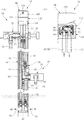
図2に柱体16,シングルレバー水栓35の内部構造が、また図3に単水栓18の内部構造が具体的に示してある。
図2に示しているように、柱体16は内部が中空とされており、中空内部に水配管としてのサプライ管38,40及び湯配管としてのサプライ管42が収納されている。
ここでサプライ管38,40,42はそれぞれフレキ管(フレキシブル管)にて構成されている。詳しくはゴム等の弾性チューブの外周面を可撓性の金属材にて被覆した形態のフレキシブル管にて構成されている。
FIG. 2 specifically shows the internal structure of the
As shown in FIG. 2, the
Here, the
栓体16の下部の土中に埋設される部分には、接続部材48が設けられていて、その接続部材48の接続口44,46に、図示を省略する外部の水配管及び湯配管がそれぞれ接続されるようになっている。
そしてこの接続部材48の接続口44に連通するようにして、上記のサプライ管38の下端部が接続され、また湯の接続口46に連通するようにして、湯側のサプライ管42の下端部がかかる接続部材48に接続されている。
A
The lower end of the
水側のサプライ管38と40との間には、流路を分岐させる分岐部材50が接続されており、水側の流路がこの分岐部材50にて流路52と54とに分岐されている。
サプライ管38を通じて給水された水は、この流路54を通じて単水栓18における水栓本体20内部に流入し、続いて吐水管26側に流れ込んで、先端の吐水口24から吐水される。
尚56は、流路52を流通する水の流量を調整するための流量調整栓である。
A
The water supplied through the
柱体16の上端部には、サプライ管38,40及び42を通じて上向きに送られてきた水と湯とを所定比率で混合し、適温の温調水とするための、上記シングルレバー水栓35における混合弁58が設けられている。
The
混合弁58は、セラミックディスクから成る固定弁体64と、固定弁体64に対して摺動運動する可動弁体66とを有している。
固定弁体64には水,湯の流入口68が設けられており、そこに上記のサプライ管40と42との上端部がそれぞれ接続されている。
The mixing
The fixed
固定弁体64にはまた流出口72が設けられていて、その流出口72に、流出管74の上端部が接続されている。
混合弁58は水、湯の流入口68から流入した水と湯とを、可動弁体66の混合室70に流入させてそこで混合し、そして混合水を流出口72から流出管74へと流出させる。
The fixed
The mixing
流出管74に流出した混合水は、図2(A)に示すシャワーフック32内部に形成された流路75に流入した後、続いてシャワーホース78を通じ上記のシャワーヘッド36へと導かれる。
混合弁58では、可動弁体66の位置を移動させることによって、水と湯との混合比率を調整し、或いはまた水,湯の一方の流入口又は両方の流入口を閉鎖する。
而して両方の流入口が閉鎖された状態において、シャワーヘッド36からの吐水が停止される。即ち止水される。
尚、柱体16の内部にはその空隙部分に保温材86が充填されている。
The mixed water that has flowed out to the
The mixing
Thus, water discharge from the
In addition, the inside of the
一方上記単水栓18は、図3に示しているように内部に弁体88を有しており、その弁体88が、スピンドル90の回転によって弁座92に対し進退移動するようになっている。
ここでスピンドル90には雄ねじ部94が設けられており、スピンドル90を回転させるとねじ送りで弁体88が進退移動させられる。
尚96は、スピンドル90を回転駆動するための駆動用の軸部である。
On the other hand, the
Here, the
図1及び図2において、98はシングルレバー水栓35におけるハンドルで、このハンドル98は、平面形状が円形で逆カップ状をなすハンドル基部100と、ハンドル基部100から洗い場12側に向って前方に突き出したレバー部102とを有している。
そしてそのハンドル基部100が、図4に示してるように連結アーム104を介して上記の混合弁58における可動弁体66に作動的に連結されている。
1 and 2,
The
このシングルレバー水栓35では、レバー部102を上向きに回動操作することで、シャワーヘッド36からの吐水が開始され、またその回動量を多くすることで吐水流量が増大せしめられる。
また逆にレバー部102を下向きに回動操作することで、吐水の流量が減少し、最終的に止水に到る。
一方レバー部102を左右に回動操作することで、湯と水の混合比率が変化せしめられ、混合水即ち吐水の温度が調節される。
In the
On the other hand, by turning the
On the other hand, by rotating the
この実施形態においては、レバー部102がハンドル基部100と別体とされていて、ハンドル基部100に対して抜差し可能となしてあり、レバー部102が水栓使用のためのキーとなしてある。
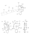
レバー部102は、図5にも示しているように所定肉厚の扁平形状且つ円形のリング状をなす入力部106と、これから突き出した軸部108と、軸部108の先端部から軸直角方向に突出した鍔状の掛止部110を有している。
ここで掛止部110は、全体として軸部108の軸心周りに非円形状を成している。
In this embodiment, the
As shown in FIG. 5, the
Here, the latching
これら掛止部110と軸部108とには、先端で開口した非円形状の、ここでは四角形状の係合孔112が設けられている。
一方、図6に示しているようにハンドル基部100の周壁部114には、掛止部110に対応した形状の貫通の差込孔116がキー孔として設けられている。
Each of the latching
On the other hand, as shown in FIG. 6, the
この実施形態では、図10(I)及び図11(I)に示しているようにレバー部102をリング状の入力部106が上下方向の縦向きとなる姿勢として、掛止部110及び軸部108の先端部をこの差込孔116内に差し込む。
そして図11(C)に示すように差込後にレバー部102を90度回転することで、詳しくは入力部106が水平方向の横向き姿勢となるまで回転することで、掛止部110がハンドル基部100の内側で周壁部114に係合した状態となる。
詳しくは、図11(C)に示しているように掛止部110が、ハンドル基部100の内側で差込孔116の縁部に掛止した状態となる。
ここにおいてレバー部102がハンドル基部100から抜け防止された状態となる。
即ちこの実施形態では、掛止部110及び掛止部110に対応した形状のハンドル基部100の差込孔116、及び周壁部114における差込孔116の縁部にて、レバー部102を抜け防止する抜止機構が構成されている。
In this embodiment, as shown in FIG. 10 (I) and FIG. 11 (I), the
Then, as shown in FIG. 11C, the
Specifically, as shown in FIG. 11C, the latching
Here, the
That is, in this embodiment, the
図4に示しているように、ハンドル基部100には軸体118が回転可能に組み付けられている。
軸体118は、図7に示しているように図中右端部と軸方向中間部とが断面円形をなしており、それらの部分が、ハンドル基部100に設けられた断面円形の支持孔120,122にて回転可能に支持されている。
As shown in FIG. 4, a
As shown in FIG. 7, the
軸体118は、図中左端側がレバー部102における上記の係合孔112に対応した断面四角形状をなし、レバー部102の係合孔112に嵌入して係合するレバー係合部124とされ、またハンドル基部100における支持孔120と122との間の部分が、後述するロック片に嵌り合って係合するロック片係合部126とされている。このロック片係合部126もまた断面四角形状をなしている。
この軸体118は、レバー部102をハンドル基部100の差込孔116内に差し込んだときに、レバー係合部124がレバー部102の係合孔112内に嵌り込んで係合し、その後レバー部102の回転に伴って、かかる軸体118が一体に回転せしめられる。
The
In the
尚、図4に示しているようにハンドル基部100には、差込孔116を内側から閉鎖する閉鎖部材128が設けられていて、この閉鎖部材128が軸体118に軸方向に移動可能に嵌装されるとともに、圧縮コイルばねから成るばね(付勢手段)130にて図中左向き、即ち差込孔116を閉鎖する方向に付勢されている。
従ってレバー102をハンドル基部100の差込孔116に差し込むときには、図10に示しているようにこの閉鎖部材128をばね130の付勢力に抗して図中右向きに押し込みながら、差込孔116に差し込む。
そしてその差込みによって、係合孔112と軸体118のレバー係合部124とを一体回転状態に係合させる。
As shown in FIG. 4, the
Therefore, when the
And by the insertion, the engaging
上記ロック片132は、レバー部102がハンドル基部100の差込孔116から抜き出されたときに、ハンドル基部100を止水状態にロックする働きをなすもので、図8に示しているように円形の基部134を有しており、これから当接アーム136が軸直角方向に延び出している。
また基部134の中心部には、上記軸体118におけるロック片係合部126の断面形状に対応した、四角形状の貫通の係合孔138が設けられている。
ロック片132は、この係合孔138において軸体118のロック片係合部126に嵌り合って係合し、ロック片132が軸体118と一体に回転運動する。即ちレバー部102の回転によってかかるロック片132が一体に回転する。
The
In addition, a rectangular through-hole
The
ロック片132は、図4及び図9(I)に示しているようにレバー部102の抜出状態の下で、当接アーム136が水栓本体146側の当接部、ここでは弁カートリッジを水栓本体146のハウジングに固定する固定ナット148に当接した状態となり、ハンドル基部1008を止水状態にロックする。
即ちハンドル基部98の図中右方向(時計方向)の回動運動を阻止した状態となって、ハンドル基部100の右方向の回動により混合弁58における可動弁体66が吐水開始方向に摺動運動するのを阻止する。
As shown in FIGS. 4 and 9I, the
In other words, the
そしてレバー部102がハンドル基部100に差し込まれ、その後90度回転せしめられることで、図9及び図11に示すように軸体118と一体にロック片132が回転運動し、当接アーム136をともに90度回転させて、当接アーム136を固定ナット148への当接作用位置から90度回転した退避位置へと位置させる。
この状態において、はじめてハンドル基部100が吐水方向に回動可能となる。
Then, the
In this state, the
図9に示しているように、ハンドル基部100にはクリック機構150の一要素をなすばね、ここでは板ばね152が組み付けられており、これに対応してロック片132の外周面には、図8にも示しているように周方向に隣接して板ばね152を嵌入させるクリック溝140-1,140-2が設けられている。尚これらクリック溝140-1と140-2との間の部分は壁142とされている。
As shown in FIG. 9, a spring that forms one element of the
このクリック機構150は次のように作用する。
図9(I)は、ロック片132における当接アーム136が水栓本体146側の当接部である固定ナット148に当接した状態にあって、ハンドル基部100を止水状態にロックした状態にある。
この状態でレバー部102が回転操作されると、軸体118を介してロック片132が90度回転せしめられる。
The
FIG. 9I shows a state in which the
When the
このとき、クリック機構150における板ばね152が、ロック片132における一方のクリック溝140-1に嵌り合った状態から、壁142を乗り越えて(図9(II)参照)、今一方のクリック溝140-2内に弾性力で勢い良く嵌り込み(図9(III)参照)、そこでクリック感を発生させる。
そのクック感は、軸体118を介してレバー部102に伝えられ、使用者はロック片132が退避位置まで90度回転したことを、触感により或いはその際のクリック音により知ることができる。
またそのクリック機構150により、詳しくは板ばね152がクリック溝140-2に嵌り込むことによって、そこでロック片132の更なる回転が抑制される。即ちロック片132及びレバー部102に対する位置決め作用が及ぼされる。
At this time, the
The feeling of cooking is transmitted to the
Further, the
尚、レバー部102を逆方向に回転操作したときには、ロック片132は、図9(III)に示す状態から図9(II)に示す状態を経て、再び図9(I)に示すまで回転せしめられる。
このときロック片132は、基部134から突出する状態に設けたストッパ部144が、ハンドル基部100の上壁部の内面に当ってストッパ作用をなし、そこでロック片132,軸体118及びレバー部102の更なる回転が阻止される。
即ちレバー部102が、差込孔116から抜出し可能な位置に位置決めされる。
When the
At this time, the
That is, the
尚、ロック片132が図9(III)に示す状態から図9(I)に示す状態に回転させられたときにおいても、板ばね152がクリック溝140-1に嵌り込んで、そこでクリック感を発生させる。
従ってレバー部102をハンドル基部100から抜き出すべく回転させたときに、そのクリック機構150によるクリック感と、ロック片132に設けたストッパ部144のストッパ作用とにより、レバー部102が抜出し可能な位置に到ったことを知ることができる。
Even when the
Therefore, when the
次に本実施形態の作用を、図10〜図13に基づいて以下に説明する。
図10(I)は、抜出状態にあるレバー部102をハンドル基部100に差し込む直前の状態を表している。
このときレバー部102を、扁平形状をなす入力部106が上下の縦向きとなる姿勢にしておく。
その状態で図12(I)に示すように掛止部110をハンドル基部100の差込孔116に合致させた状態として、レバー部102を図中右向きに押し込み、レバー部102の軸部108を掛止部110の側からハンドル基部100内部に差し込む。
このとき、図10(II)に示しているように軸体118における図中左端側のレバー係合部124が、レバー部102の係合孔112内に入り込んだ状態となって、レバー係合部124とレバー部102とが係合し、一体に回転する状態となる。
Next, the operation of this embodiment will be described below with reference to FIGS.
FIG. 10I shows a state immediately before the
At this time, the
In this state, as shown in FIG. 12 (I), with the latching
At this time, as shown in FIG. 10 (II), the
図11(I)はこのときの状態を示している。
この状態から、図12(II),(III)及び図11(II)に示しているようにレバー部102を90度回転操作すると、ここにおいて図11(II)(B)及び(C)、更に図12(III)に示しているように、レバー部102における掛止部110が、ハンドル基部100における周壁部114の差込孔116周りの縁部に掛止した状態となり、ここにおいてレバー部102がハンドル基部102から抜け防止される。
これと同時に、レバー部102と一体回転するロック片132が図9(I)に示す状態から図9(III)に示す状態となって、ロック片132によるハンドル基部100の止水ロック状態が解除され、ハンドル基部100が吐水方向に回動可能となる。
FIG. 11I shows the state at this time.
From this state, when the
At the same time, the
そこで、90度の回転により図13に示しているように入力部106が水平方向の横向き姿勢となったレバー部102に対し、図中上向きの回動操作力を加えることで、レバー部102とハンドル基部100とが一体になって、即ちハンドル98全体が図中右方向(時計方向)に回動し、ここにおいてシングルレバー水栓35における吐水動作が行われる。
更にその状態でレバー部102に対し水平且つ左右方向に回動操作力を加えることで、レバー部102及びハンドル基部100即ちハンドル98全体が左右方向に回動運動し、ここにおいてシングルレバー水栓35における吐水の温度調節動作が行われる。
Therefore, by applying an upward turning operation force in the drawing to the
In this state, the
一方シングルレバー水栓35の使用を終了したところで、レバー部102を再び逆方向に90度回転操作することで、これをハンドル基部100から抜き出すことができる。
このとき、ロック片132が再びハンドル基部100を止水状態にロックした状態となり、従ってレバー部102を抜き出すことによって、シングルレバー水栓35がその後使用不能状態となる。
On the other hand, when the use of the
At this time, the
本実施形態において、レバー部102はまた、上記の単水栓18における脱着可能なハンドルを兼ねて構成してある。
このレバー部102を、単水栓18のハンドルとして取り付けるときには、図3に示しているようにスピンドル90に設けた断面四角形状の駆動用の軸部96を、レバー部102の係合孔112に嵌め合せるようにして、レバー部102の掛止部110及び軸部108を、単水栓18における水栓本体20のハウジング内部に、差込孔116を通じて差し込む。
In the present embodiment, the
When the
これによりレバー部102と軸部96、即ちスピンドル90が一体回転状態に連結される。従ってその状態でレバー部102を回転操作すると、その時点でレバー部102が単水栓18の水栓本体20におけるハウジングから抜け防止されるとともに、スピンドル90の回転によって弁体88が弁座92から離間せしめられ、単水栓18における吐水動作が行われる。
また単水栓18を再び止水した状態の下で、レバー部102が再び差込孔116から抜出し可能となる。
As a result, the
Further, the
以上のように本実施形態によれば、ハンドル基部100に対して別体となしてあるレバー部102をハンドル基部100から抜き出しておくことで、シングルレバー水栓35を使用不能状態となすことができ、これによりシングルレバー水栓35が悪戯使用されたり、或いは不正使用されたりするのを有効に防止することができる。
As described above, according to the present embodiment, the
また本実施形態では、ハンドル基部100に差し込んだレバー部102を抜け防止する抜止機構が設けてあるため、レバー部102をハンドル基部100に差し込んだ後においてこれを回動操作する際、誤ってレバー部102がハンドル基部100から抜けてしまうといった不都合を防止でき、通常のシングルレバー水栓と同様に使い勝手良くシングルレバー水栓35を使用することができる。
Further, in this embodiment, since a retaining mechanism for preventing the
本実施形態ではまた、ハンドル基部100を止水状態にロックするロック機構が設けてあることから、レバー部102をハンドル基部100から抜き出すことによって、単にレバー部102を操作してシングルレバー水栓35を吐水操作することができなくなるのみならず、混合弁58における可動弁体66を摺動運動させるハンドル基部100自体が止水状態にロックされるため、シングルレバー水栓35の悪戯使用や不正使用をより確実に防止することができる。
In the present embodiment, since a lock mechanism for locking the
一方でレバー部102を差し込んで使用可能な水平姿勢に回転させることによって簡単にロック機構をロック解除でき、支障なくシングルレバー水栓35を使用することが可能となる。
On the other hand, the locking mechanism can be easily unlocked by inserting the
本実施形態ではそのロック機構が、ハンドル基部100から延び出した回転可能なロック片132を有するものとなし、且つそのロック片132は、ロック作用時には水栓本体146の固定ナット148に当接してハンドル基部100の吐水方向への回動を阻止する一方、ハンドル基部100に差し込まれたレバー部102の回転により当接作用位置から退避位置まで回転運動して、ハンドル基部100の吐水方向への回動を許容するものとなしてあり、ロック機構を簡単な構造で構成することができる。
In the present embodiment, the locking mechanism has a
本実施形態ではまた、レバー部102を、水栓柱10にシングルレバー水栓35と併せて設置されている単水栓18の脱着可能なハンドルを兼ねて構成してあるため、レバー部102をシングルレバー水栓35,単水栓18の何れに対しても共通のキーとして且つ操作部分として共用することができ、シングルレバー水栓35のみならず、水栓柱10に備えられた別の単水栓18の悪戯使用や不正使用も併せて防止することができる。
In the present embodiment, the
またシングルレバー水栓35,単水栓18それぞれに悪戯使用や不正使用を防止するためのキーを別々に備えておかなくても良く、共通のキー(レバー部102)にて対応できる利点が得られる。
Further, the
上記実施形態において、閉鎖部材128は、ロック機構におけるロック解除を禁止する解除禁止部材として構成しておくことができる。
図14及び図15はその具体例を示している。
これらの図において、閉鎖部材128には上端に切落し形状の平坦な係合面154が形成されており、レバー部102の抜出状態の下でこの閉鎖部材128が係合面154においてハンドル基部100側の突出部156に形成された対応形状の係合面158に係合し、軸体118即ちロック片132の回転によるロック解除を禁止する解除禁止部材となしてある。
In the above-described embodiment, the closing
14 and 15 show specific examples thereof.
In these drawings, the closing
而してレバー部102をハンドル基部98内部に押し込むと、当初図14及び図15(I)に示すように解除禁止状態にあった閉鎖部材128が、図15(II)に示しているようにレバー部102によりハンドル基部100内部に深く押し込まれて移動し、閉鎖部材128における係合面154とハンドル基部100側の係合面158との係合が外れた状態となる。
Thus, when the
この時点で閉鎖部材128によるロック解除禁止の状態が解かれ、ここにおいて軸体118の回転によるロック片132のロック解除動作が許容される状態となる。
尚、閉鎖部材128には中心部に四角形状の係合孔160が形成されていて、この係合孔160において閉鎖部材128が軸体118におけるレバー係合部124に係合し、軸体118と一体回転するようになっている。
この点は図1〜図13に示す上記実施形態の閉鎖部材128においても同様である。
At this time, the unlocking prohibition state by the closing
The
This also applies to the closing
以上本発明の実施形態を詳述したが、これはあくまで一例示である。
例えば本発明は上記の水栓柱に備えられたシングルレバー水栓のみならず、屋外に設置されている他の種々形態のシングルレバー水栓或いは屋内,屋外を問わず他の様々なシングルレバー水栓に適用可能である等、本発明はその趣旨を逸脱しない範囲において種々変更を加えた形態で構成可能である。
Although the embodiment of the present invention has been described in detail above, this is merely an example.
For example, the present invention is not limited to the single lever faucet provided in the faucet column described above, but various other types of single lever faucets installed outdoors or various other single lever faucets, both indoors and outdoors. The present invention can be configured in various modifications without departing from the spirit of the present invention, such as being applicable to a stopper.
10 水栓柱
18 単水栓
35 シングルレバー水栓
58 混合弁
64 固定弁体
66 可動弁体
98 ハンドル
100 ハンドル基部
102 レバー部
104 連結アーム
106 入力部
108 軸部
110 掛止部
114 周壁部
116 差込孔
132 ロック片
136 当接アーム
148 固定ナット(当接部)
DESCRIPTION OF
Claims (11)
前記レバー部を前記ハンドル基部と別体となして該ハンドル基部に対し抜差し可能となし、該レバー部を水栓使用のためのキーとなしてあることを特徴とするシングルレバー水栓。 (A) a mixing valve that adjusts the temperature of water discharge and water discharge by sliding movement of the movable valve body with respect to the fixed valve body, (b) a handle base portion connected to the movable valve body via a connection arm, and A handle provided with a lever portion protruding from the handle base, and the movable valve body is slid through the handle base and the connecting arm by rotating the lever. In the single lever faucet, the lever portion is separated from the handle base portion so that it can be inserted into and removed from the handle base portion, and the lever portion serves as a key for use of the faucet. Lever faucet.
Priority Applications (1)
| Application Number | Priority Date | Filing Date | Title |
|---|---|---|---|
| JP2007273241A JP5077882B2 (en) | 2007-10-20 | 2007-10-20 | Single lever faucet |
Applications Claiming Priority (1)
| Application Number | Priority Date | Filing Date | Title |
|---|---|---|---|
| JP2007273241A JP5077882B2 (en) | 2007-10-20 | 2007-10-20 | Single lever faucet |
Publications (2)
| Publication Number | Publication Date |
|---|---|
| JP2009103148A true JP2009103148A (en) | 2009-05-14 |
| JP5077882B2 JP5077882B2 (en) | 2012-11-21 |
Family
ID=40705044
Family Applications (1)
| Application Number | Title | Priority Date | Filing Date |
|---|---|---|---|
| JP2007273241A Active JP5077882B2 (en) | 2007-10-20 | 2007-10-20 | Single lever faucet |
Country Status (1)
| Country | Link |
|---|---|
| JP (1) | JP5077882B2 (en) |
Cited By (2)
| Publication number | Priority date | Publication date | Assignee | Title |
|---|---|---|---|---|
| JP2020022303A (en) * | 2018-08-02 | 2020-02-06 | 中国電力株式会社 | Ground short circuit device |
| CN113738897A (en) * | 2021-09-06 | 2021-12-03 | 陆少华 | Anti-locking stop valve |
Citations (5)
| Publication number | Priority date | Publication date | Assignee | Title |
|---|---|---|---|---|
| JPS5845480U (en) * | 1981-09-24 | 1983-03-26 | 前沢給装工業株式会社 | valve |
| JPS61126166U (en) * | 1985-01-25 | 1986-08-08 | ||
| JPS63185977U (en) * | 1987-05-25 | 1988-11-29 | ||
| JPH10176350A (en) * | 1996-12-19 | 1998-06-30 | Inax Corp | Outdoor water discharge device |
| JP2005120717A (en) * | 2003-10-17 | 2005-05-12 | Mym Corp | Cock pole |
-
2007
- 2007-10-20 JP JP2007273241A patent/JP5077882B2/en active Active
Patent Citations (5)
| Publication number | Priority date | Publication date | Assignee | Title |
|---|---|---|---|---|
| JPS5845480U (en) * | 1981-09-24 | 1983-03-26 | 前沢給装工業株式会社 | valve |
| JPS61126166U (en) * | 1985-01-25 | 1986-08-08 | ||
| JPS63185977U (en) * | 1987-05-25 | 1988-11-29 | ||
| JPH10176350A (en) * | 1996-12-19 | 1998-06-30 | Inax Corp | Outdoor water discharge device |
| JP2005120717A (en) * | 2003-10-17 | 2005-05-12 | Mym Corp | Cock pole |
Cited By (4)
| Publication number | Priority date | Publication date | Assignee | Title |
|---|---|---|---|---|
| JP2020022303A (en) * | 2018-08-02 | 2020-02-06 | 中国電力株式会社 | Ground short circuit device |
| JP7095469B2 (en) | 2018-08-02 | 2022-07-05 | 中国電力株式会社 | Ground short circuit device |
| CN113738897A (en) * | 2021-09-06 | 2021-12-03 | 陆少华 | Anti-locking stop valve |
| CN113738897B (en) * | 2021-09-06 | 2023-11-24 | 天津市中核科技实业有限公司 | Anti-lock stop valve |
Also Published As
| Publication number | Publication date |
|---|---|
| JP5077882B2 (en) | 2012-11-21 |
Similar Documents
| Publication | Publication Date | Title |
|---|---|---|
| US10274096B2 (en) | Touch faucet | |
| JP2013545909A (en) | Faucet mounting type eyewash unit | |
| US8220492B2 (en) | Faucet device | |
| JP5088736B2 (en) | Single lever faucet | |
| US7861742B2 (en) | Cartridge of water supply valve | |
| JP2010053889A (en) | Water stop valve apparatus and water supply equipment using the same | |
| CN104879556A (en) | Touch control type tap | |
| US20060157128A1 (en) | Swing spout with positional locking device | |
| JP5077882B2 (en) | Single lever faucet | |
| KR100797519B1 (en) | A cartridge of water suppling valve | |
| KR102445481B1 (en) | Cold and hot water faucet for direct connection to water | |
| KR101203450B1 (en) | a faucet for preventing scalder | |
| US8276876B2 (en) | Limiter for water faucets equipped with lever-type handles | |
| US7121303B1 (en) | Mixed water faucet | |
| JP2016069909A (en) | Water saving device for shower equipment | |
| JP2002285595A (en) | Safety cover for water shut off valve | |
| JP2006275248A (en) | Valve device for faucet | |
| KR101496264B1 (en) | Water suppling valve for single lever | |
| WO2019044406A1 (en) | Faucet device | |
| JP2001279741A (en) | Receptacle for water works | |
| KR200285321Y1 (en) | Beverage dispensing valve | |
| JPS5919164Y2 (en) | Liquid supply valve discharge flow rate setting device | |
| JP5978546B2 (en) | Water-saving device for shower facilities | |
| TWI522558B (en) | Kitchen plastic faucet structure | |
| TWM604851U (en) | Hot and cold water mixing faucet with safety pressing part |
Legal Events
| Date | Code | Title | Description |
|---|---|---|---|
| A621 | Written request for application examination |
Free format text: JAPANESE INTERMEDIATE CODE: A621 Effective date: 20100621 |
|
| A711 | Notification of change in applicant |
Free format text: JAPANESE INTERMEDIATE CODE: A712 Effective date: 20110523 |
|
| A977 | Report on retrieval |
Free format text: JAPANESE INTERMEDIATE CODE: A971007 Effective date: 20120522 |
|
| A131 | Notification of reasons for refusal |
Free format text: JAPANESE INTERMEDIATE CODE: A131 Effective date: 20120605 |
|
| A521 | Written amendment |
Free format text: JAPANESE INTERMEDIATE CODE: A523 Effective date: 20120723 |
|
| TRDD | Decision of grant or rejection written | ||
| A01 | Written decision to grant a patent or to grant a registration (utility model) |
Free format text: JAPANESE INTERMEDIATE CODE: A01 Effective date: 20120821 |
|
| A01 | Written decision to grant a patent or to grant a registration (utility model) |
Free format text: JAPANESE INTERMEDIATE CODE: A01 |
|
| A61 | First payment of annual fees (during grant procedure) |
Free format text: JAPANESE INTERMEDIATE CODE: A61 Effective date: 20120821 |
|
| FPAY | Renewal fee payment (event date is renewal date of database) |
Free format text: PAYMENT UNTIL: 20150907 Year of fee payment: 3 |
|
| R150 | Certificate of patent or registration of utility model |
Ref document number: 5077882 Country of ref document: JP Free format text: JAPANESE INTERMEDIATE CODE: R150 Free format text: JAPANESE INTERMEDIATE CODE: R150 |
|
| S111 | Request for change of ownership or part of ownership |
Free format text: JAPANESE INTERMEDIATE CODE: R313111 |
|
| R350 | Written notification of registration of transfer |
Free format text: JAPANESE INTERMEDIATE CODE: R350 |