JP2009102012A - Seat belt device - Google Patents
Seat belt device Download PDFInfo
- Publication number
- JP2009102012A JP2009102012A JP2009026044A JP2009026044A JP2009102012A JP 2009102012 A JP2009102012 A JP 2009102012A JP 2009026044 A JP2009026044 A JP 2009026044A JP 2009026044 A JP2009026044 A JP 2009026044A JP 2009102012 A JP2009102012 A JP 2009102012A
- Authority
- JP
- Japan
- Prior art keywords
- seat belt
- motor
- belt
- reel
- slack
- Prior art date
- Legal status (The legal status is an assumption and is not a legal conclusion. Google has not performed a legal analysis and makes no representation as to the accuracy of the status listed.)
- Granted
Links
Images


Abstract
Description
本発明は、車両の衝突の際に乗員を座席にシートベルトで拘束することによって乗員の安全を図るシートベルト装置に関し、特に、電動モータ等の動力源によってシートベルトの張力を可変としたシートベルト装置に関する。 TECHNICAL FIELD The present invention relates to a seat belt device that secures an occupant by restraining the occupant to a seat with a seat belt in the event of a vehicle collision, and in particular, a seat belt in which the tension of the seat belt is variable by a power source such as an electric motor. Relates to the device.
従来、車両の衝突予知を行い、衝突前に電動モータによってシートベルトを巻取り、衝突時の乗員を拘束するようにした車両のシートベルト装置が提案されている。電動モータを用いたシートベルト巻取り装置では、どの程度の量のシートベルトを巻取ることが出来るか、どの程度の速さでシートベルトを巻取ることが出来るか、が重要である。それにより、シートベルトの除去可能な弛みの程度と、衝突予測にかけることのできる時間が定るからである。 2. Description of the Related Art Conventionally, there has been proposed a vehicle seat belt device that predicts a vehicle collision, winds up a seat belt with an electric motor before the collision, and restrains an occupant at the time of the collision. In a seat belt retractor using an electric motor, it is important to determine how much of the seat belt can be wound and how fast the seat belt can be wound. This is because the degree of slack that can be removed from the seat belt and the time that can be taken for collision prediction are determined.
例えば、特開平9−132113号により提案されている「車両の乗員保護システム」においては、衝突の危険がない場合には、コンフォートモードという状態にある。この状態は、電動モータでベルトを巻取り、ベルトテンションが2kgから3kgになるとモータを停止し、若干の時間経過後、徐々に電動モータを引出し方向に回転駆動し、ベルトテンションが0kgになったときに電動モータを停止して得られる状態である。従って、張力が0kgで乗員に圧迫感がなくかつシートベルトに弛みのない状態である。このコンフォートモードにおいて、各種の危険を示す信号が発生すると、電動モータを駆動してシートベルトを巻取り、シートベルトの張力を増加させて乗員を座席に拘束するようにしている。 For example, in the “vehicle occupant protection system” proposed in Japanese Patent Laid-Open No. 9-132113, when there is no danger of a collision, the vehicle is in the comfort mode. In this state, the belt is wound around with the electric motor, and when the belt tension is changed from 2 kg to 3 kg, the motor is stopped, and after a certain period of time, the electric motor is gradually rotated in the drawing direction, and the belt tension becomes 0 kg. This is sometimes obtained by stopping the electric motor. Therefore, the tension is 0 kg, the occupant has no feeling of pressure, and the seat belt is not slack. In this comfort mode, when signals indicating various dangers are generated, the electric motor is driven to wind up the seat belt, and the tension of the seat belt is increased to restrain the occupant to the seat.
しかしながら、弛みのない状態からシートベルトを巻取ろうとすると、電動モータには、ベルト巻取りの初期段階から乗員を拘束する負荷が加わり、電動モータが十分な回転速度に上がらない状態でベルト巻取りを行うことになる。このため、衝突が避けられない場合に必要とされるシートベルト巻取り量を確保するためには大きい力を必要とし、回転トルクの大きい電動モータが必要である。この種モータは、形状が大きく、重量が重く、コストも高い。また、小型の電動モータを用い、減速機を用いて大きなトルクを得る場合には、減速比を大きくしなければならないので、その分、巻取り速度が遅くなる。 However, if the seat belt is to be wound from a state where there is no slack, a load that restrains the occupant is applied to the electric motor from the initial stage of the belt winding, and the belt is wound while the electric motor does not reach a sufficient rotational speed. Will do. For this reason, in order to ensure the seat belt winding amount required when a collision is unavoidable, a large force is required and an electric motor having a large rotational torque is required. This type of motor is large in shape, heavy and expensive. Further, when a small electric motor is used and a large torque is obtained by using a reduction gear, the reduction ratio must be increased, so that the winding speed is reduced accordingly.
よって、本発明は、比較的に小型のモータを用いて素早くシートベルトを巻取ることを可能としたシートベルト装置を提供することを目的とする。 Therefore, an object of the present invention is to provide a seat belt device that can quickly wind up a seat belt using a relatively small motor.
上記目的を達成するため本発明のシートベルト装置は、乗員を座席に拘束するシートベルトを巻回するリールと、上記リールを回転駆動するモータと、上記シートベルトを上記リールに巻取る際に、上記モータを上記シートベルトの引出し方向に暫時駆動してシートベルトを弛め、その後に上記モータをシートベルトの巻取り方向に駆動して、モータ起動の際の負荷を減じてシートベルトの巻取りを高速で行えるように制御する制御手段と、を備える。 In order to achieve the above object, the seat belt device of the present invention comprises a reel that winds a seat belt that restrains an occupant to a seat, a motor that rotationally drives the reel, and when the seat belt is wound around the reel. Drive the motor for a while in the seat belt pull-out direction to loosen the seat belt, and then drive the motor in the seat belt retracting direction to reduce the load when starting the motor to retract the seat belt. And a control means for controlling so as to be performed at high speed.
かかる構成とすることによって、モータを作動させる初期の立上がり段階において、モータの負荷は略無負荷状態となり、モータは起動後、急速に回転速度を上昇する。弛んだシートベルトを巻取って乗員の拘束が始る時点では、相当の回転速度となる。この高い回転速度で乗員の拘束が始れば、最初から乗員を拘束する負荷を担う場合に比べて、より俊敏にベルトを巻上げ、結果的には、低い回転数で直ちにベルトを巻上げる場合よりもより早く乗員を座席に拘束することが可能となる。 With this configuration, the motor load is substantially in the no-load state at the initial rising stage of operating the motor, and the motor rapidly increases in rotational speed after startup. When the seat belt that has slackened is wound up and the occupant begins to be restrained, the rotational speed is considerably high. If the occupant restraint starts at this high rotational speed, the belt is wound more quickly than the case where the occupant is restrained from the beginning, and as a result, the belt is wound immediately at a lower rotational speed. It becomes possible to restrain an occupant to a seat earlier.
また、本発明のシートベルト装置は、乗員を座席に拘束するシートベルトを巻回するリールと、上記シートベルトの装着を検知するシートベルト装着検知手段と、上記リールを上記シートベルトの巻取り方向あるいは上記シートベルトの引出し方向に回転させるモータと、上記モータの回転駆動を制御する制御手段と、を備え、上記制御手段は、上記シートベルトの装着が検知されると、上記モータをシートベルトの弛みが除去されるまで巻取り方向に駆動し、該弛みが除去されると、上記シートベルトを上記モータの低負荷起動に必要な分だけ予め弛ませておくべく引出し方向に駆動する。 The seat belt device of the present invention includes a reel that winds a seat belt that restrains an occupant to a seat, seat belt wearing detection means that detects wearing of the seat belt, and a winding direction of the seat belt. Or a motor for rotating the seat belt in the pull-out direction; and a control means for controlling the rotational drive of the motor. When the seat belt is detected, the control means moves the motor to the seat belt. The sheet belt is driven in the winding direction until the slack is removed, and when the slack is removed, the seat belt is driven in the pull-out direction so that the seat belt is slackened in advance by the amount necessary for starting the low load of the motor.
好ましくは、上記制御手段は、上記シートベルトの弛みの除去をシートベルトの張力が所定値になることによって検出し、該張力を上記モータへの供給電流の値によって推定する。 Preferably, the control means detects the removal of the slack of the seat belt when the tension of the seat belt becomes a predetermined value, and estimates the tension based on the value of the current supplied to the motor.
好ましくは、上記制御手段は、上記低負荷立上がりに必要な分の弛みとして、20mmから40mmである。 Preferably, the control means is 20 mm to 40 mm as a slack necessary for the low load rising.
本発明のシートベルト装置は、乗員を座席に拘束するシートベルトを巻回するリールと、指令信号に応じて上記リールからのシートベルトの引出しを禁止する共に、上記リールへの上記シートベルトの巻取りを許容する強制ロック機構と、車両の衝突を予知し、衝突が不可避的であるときに衝突不可避信号を出力する衝突予知手段と、上記リールを上記シートベルトの巻取り方向あるいは上記シートベルトの引出し方向に回転駆動するモータと、上記衝突不可避信号を受けて上記モータを制御する制御手段と、を備え、上記制御手段は、上記衝突不可避信号が出力されると、上記モータをシートベルトの引出し方向に暫時駆動し、その後、上記モータをシートベルトの巻取り方向に駆動すると共に上記強制ロック機構をも作動させる。 The seat belt device according to the present invention includes a reel that winds a seat belt that restrains an occupant to a seat, and prohibits the withdrawal of the seat belt from the reel in response to a command signal, and also winds the seat belt around the reel. A forcible lock mechanism that allows the vehicle to take off, a collision prediction means that predicts a vehicle collision and outputs a collision unavoidable signal when the collision is unavoidable, and the reel in the seat belt winding direction or the seat belt A motor that rotationally drives in the pull-out direction; and a control unit that controls the motor in response to the collision unavoidable signal, and the control unit pulls the motor out of the seat belt when the collision unavoidable signal is output. Then, the motor is driven in the seat belt winding direction and the forced lock mechanism is also activated.
本発明のシートベルト装置は、乗員を座席に拘束するシートベルトを巻回するリールと、車両の衝突を予知し、衝突の危険性があるが回避可能であるときに衝突可避信号を出力する衝突予知手段と、上記リールを上記シートベルトの巻取り方向あるいは上記シートベルトの引出し方向に回転駆動するモータと、上記衝突予知信号を受けて上記モータを制御する制御手段と、を備え、上記制御手段は、上記衝突可避信号が出力されると、シートベルト張力がシートベルトの弛みの少ない状態に対応する所定張力となるまで上記モータをシートベルトの巻取り方向に駆動し、該所定張力に到達後、シートベルトの弛み量が所定量となるように上記モータを引出し方向に暫時駆動する。 The seat belt device of the present invention predicts a collision between a reel that winds a seat belt that restrains an occupant to a seat and a vehicle, and outputs a collision avoidance signal when there is a risk of collision but can be avoided. A collision prediction means; a motor that rotationally drives the reel in the seat belt winding direction or the seat belt withdrawal direction; and a control means that controls the motor in response to the collision prediction signal. When the collision avoidance signal is output, the means drives the motor in the seat belt winding direction until the seat belt tension reaches a predetermined tension corresponding to a state in which the seat belt is less slackened. After reaching, the motor is driven in the pull-out direction for a while so that the amount of looseness of the seat belt becomes a predetermined amount.
本発明のシートベルト装置は、乗員を座席に拘束するシートベルトを巻回するリールと、指令信号に応じて上記リールからのシートベルトの引出しを禁止する共に、上記リールへの上記シートベルトの巻取りを許容する強制ロック機構と、車両の衝突を予知し、衝突が不可避的であるときに衝突不可避信号を出力する衝突予知手段と、上記リールを上記シートベルトの巻取り方向あるいは上記シートベルトの引出し方向に回転駆動するモータと、上記シートベルトの弛み量を検知する弛み量検知手段と、上記衝突不可避信号を受けて上記モータを制御する制御手段と、を備え、上記制御手段は、上記衝突不可避信号が出力されると、上記シートベルトの弛み量を読取り、上記弛み量が所定値以上のときには上記モータをシートベルトの巻取り方向に駆動すると共に上記強制ロック機構をも作動させ、上記弛み量が所定値よりも小さいときには、上記弛み量が所定値となるように上記モータをシートベルトの引出し方向に暫時駆動し、その後、上記モータをシートベルトの巻取り方向に駆動すると共に上記強制ロック機構をも作動させる。 The seat belt device according to the present invention includes a reel that winds a seat belt that restrains an occupant to a seat, and prohibits the withdrawal of the seat belt from the reel in response to a command signal, and also winds the seat belt around the reel. A forcible lock mechanism that allows the vehicle to take off, a collision prediction means that predicts a vehicle collision and outputs a collision unavoidable signal when the collision is unavoidable, and the reel in the seat belt winding direction or the seat belt A motor that rotationally drives in the pull-out direction; a slack amount detecting means that detects a slack amount of the seat belt; and a control means that controls the motor in response to the collision unavoidable signal. When the unavoidable signal is output, the slack amount of the seat belt is read, and when the slack amount is equal to or greater than a predetermined value, the motor is wound around the seat belt. And the forced locking mechanism is also activated.When the amount of slack is smaller than a predetermined value, the motor is temporarily driven in the seat belt withdrawing direction so that the amount of slack is a predetermined value. The motor is driven in the seat belt winding direction and the forced lock mechanism is also activated.
好ましくは、上記弛み検出手段は、シートベルトが巻回されたリールの回転軸の回転数と回転方向とを検出可能な回転センサによってシートベルトの引き出し量が検知され、シートベルトが所定張力となったときの引き出しテンションを原点として、そこから引き出された量が弛み量として検知される。 Preferably, the slack detection means detects the amount of withdrawal of the seat belt by a rotation sensor capable of detecting the rotation speed and the rotation direction of the rotation shaft of the reel around which the seat belt is wound, and the seat belt becomes a predetermined tension. The amount pulled out from the starting tension is detected as the slack amount.
また、電動モータの起動前にシートベルトに弛みを与える均等な手段として、バックルを引込む機構や、ラップベルト固定部を引込む機構に、シートベルトに弛みを与える機構を設けるようにしても良い。 Further, as an equivalent means for giving slack to the seat belt before the electric motor is started, a mechanism for giving slack to the seat belt may be provided in a mechanism for pulling the buckle or a mechanism for drawing the lap belt fixing portion.
本発明のシートベルト装置においては、モータの起動の際にモータの回転数が急上昇するに必要な程度にシートベルトを弛ませて、モータの低負荷状態からシートベルトの巻取りを開始するので、高速回転でシートベルトが巻取られ、乗員の座席への拘束を素早く行うことが可能となる。また、シートベルトの弛みが短時間で除去出来れば、衝突の判断に割当てる時間を増やすことが出来るので具合が良い。 In the seat belt device of the present invention, when starting the motor, the seat belt is slackened to the extent necessary for the motor speed to rapidly increase, and the seat belt winding is started from the low load state of the motor. The seat belt is wound up at high speed, and it is possible to quickly restrain the passenger on the seat. If the slack of the seat belt can be removed in a short time, it is possible to increase the time allocated to the collision determination, which is good.
以下、本発明の実施例について図面を参照して説明する。
まず、本発明の着目点について説明する。電動モータを作動させる初期の段階において、ある時間だけ、電動モータの負荷を略無負荷状態とすれば、電動モータは起動後、急速に回転速度を上昇する。シートベルトが所定量弛んだ状態から巻取りを開始すれば、シートベルトを巻取って乗員の拘束が始る時点では、相当の回転速度に上昇している。電動モータが最初から乗員を拘束する高い負荷を担って起動する場合に比べて、より俊敏にベルトを巻上げる。同じ電動モータ及び同じ電源を用いた場合、拘束開始点を基準としたときの電動モータによるシートベルトの最大巻取り量は、電動モータがある速度に達した段階で拘束を開始する方がより大きい。ただし、電動モータの高い初期速度を得るために、敢てシートベルトを弛ませて無負荷区間(期間)を確保するので、その分、乗員の拘束が始る拘束開始時点は遅くなる。従って、シートベルトの弛み量を必要限度に設定することによって、従来よりも、より素早い乗員拘束を完了することが可能となる。このシートベルトの弛み量は、電動モータが最大速度に達することの出来る量(最大回転速度に達するまでに回転した回転量)であることが望ましいが、最大速度に至るまでの時間を考慮すれば、最大速度の約60%以上となるような弛み量であることが好ましい。
Embodiments of the present invention will be described below with reference to the drawings.
First, the point of interest of the present invention will be described. In the initial stage of operating the electric motor, if the load of the electric motor is set to a substantially no-load state for a certain time, the electric motor rapidly increases in rotational speed after startup. If winding is started from a state where the seat belt is slackened by a predetermined amount, the rotation speed is increased to a considerable rotational speed at the time when the seat belt is wound and the occupant starts restraining. Compared to the case where the electric motor is started with a high load that restrains the occupant from the beginning, the belt is wound up more quickly. When the same electric motor and the same power source are used, the maximum amount of seat belt retracted by the electric motor when the restriction start point is used as a reference is greater when the restriction starts when the electric motor reaches a certain speed. . However, in order to obtain a high initial speed of the electric motor, the seat belt is loosened to secure a no-load section (period), and accordingly, the restraint start time at which restraint of the occupant starts is delayed. Therefore, by setting the amount of seat belt slack to the necessary limit, it is possible to complete occupant restraint that is faster than before. The slack amount of the seat belt is preferably an amount that the electric motor can reach the maximum speed (the amount of rotation that has been rotated until the maximum rotation speed is reached), but if the time to reach the maximum speed is taken into consideration The amount of slack is preferably about 60% or more of the maximum speed.
図1は、シートベルト装置を示している。シートベルト装置は、乗員を座席301に拘束するシートベルト302を巻取る電動巻取装置100、シートベルト302を乗員の肩近傍で折返すスルーアンカ303、シートベルトを挿通して腰部に配置されるバックル304と係合するタングプレート305、シートベルト302の端部を車体に固定するアンカー306、バックルに内蔵されたスイッチ307、ベルト巻取装置100のモータを制御する制御部200、車両の衝突を予知する衝突予知部401等によって構成される。
FIG. 1 shows a seat belt device. The seat belt device is disposed at the waist by inserting an electric winding
図2は、電動巻取り装置100の構成を概略的に説明する説明図である。同図において、電動巻取り装置100は、フレーム101を備えている。このフレーム101には、図示しないシートベルトを巻回するリール103、リール103と結合し、リール回転の中心軸となるリールシャフト103aが回転自在に設けられる。リールシャフト103aの右端部には、車両に所定の減速度が作用したとき又はシートベルトが所定の加速度で引出されたときにシートベルトの引出しをロックする後述のシートベルトロック機構102が固定されている。このロック機構102には、ロック機構102を強制的に作動させる後述の電磁的アクチュエータ112が更に設けられている。電磁的アクチュエータ112は後述の制御部200の出力によって作動が制御される。シートベルトロック機構102は、シートベルト引き出しのロック状態でも電動モータ110によるシートベルトの巻取りが可能に構成されている。
FIG. 2 is an explanatory diagram schematically illustrating the configuration of the electric winding
リールシャフト103aの左端部には、回転センサ113、プリテンショナ104、プーリ105、ポテンショメータ111が設けられる。
A
回転センサ113は、リール103の側壁を一周するようにかつNSの磁極が交互に多数配置された磁石113bと、リトラクタベース101に取付けられた2個の磁気センサ113aと、によって構成される。2つの磁気センサは、半周期ずらして取付けられており、リールの回転数と回転方向とを検知する。磁気センサ113aの出力は、制御部200に供給される。
The
プリテンショナ104は、図示しない衝突検出器の出力によって作動し、リールシャフト103aをシートベルトの巻取り方向に回転し、シートベルトを強制的に巻取って乗員を座席に拘束する。プリテンショナ104は、例えば、火薬式プリテンショナであり、ガス発生器、ガス発生器から発生したガスを封止するシリンダ、シリンダ内をガス圧によって移動するピストン、ピストンの移動を、クラッチ機構を介してリール軸103aの回転運動に変換する伝達機構などによって構成される。
The
リール軸103aに固定されたプーリ105は、動力伝達用ベルト107を介して直流モータ110の軸に固定されたプーリ106と連結している。プーリ105、106の外周にはそれぞれ所定数の外歯が形成され、また、ベルト107の内周にも所定数の内歯が形成されている。リールシャフト用のプーリ105、モータ用のプーリ106、ベルト107の各歯山は過不足なく噛合っており、モータ110の回転は、リールシャフト103aに伝達される。モータ110は、フレーム101に少なくとも2点以上で固定されており、制御部200の出力によって動作する。
The
リールシャフト103aの最左端に設けられたポテンショメータ111は、図5に示すように、両端に電圧が印加される抵抗体と、リールシャフト103aの回転に連動する摺動子とによって構成される。そして、リールシャフト103a基準位置からの回転量に対応した電圧値を制御部200に出力する。
As shown in FIG. 5, the
上述の例では、弛み検出の例示として、回転センサ113とポテンショメータ111とを備えているが、いずれか一方のみを備えるものであって良い。
In the above-described example, the
図3は、電動巻取り装置100の他の構成を概略的に説明する説明図である。同図において、図2と対応する部分には同一符号を付し、かかる部分の説明は省略する。この例では、リール103を巻取り方向に付勢する巻取りばね114がリールシャフト103aに設けられている。巻取りばねは、例えば、リールシャフト103aを中心にして螺旋状に巻回された弦巻ばねであり、シートベルトを引出すと、シートベルトに巻取り方向の弱いテンションを与える。
FIG. 3 is an explanatory diagram schematically illustrating another configuration of the electric winding
図4は、制御部200の概略構成を説明する機能ブロック図である。同図に示されるように、制御部200は、マイクロコンピュータシステムによって構成される。CPU201は、ROM202に保持される制御プログラムやデータをRAM203のワークエリアにロードしてモータ110及びシートベルトロック機構102を強制的に作動させる電磁的アクチュエータ(例えば、ソレノイド)112の動作を制御する。
FIG. 4 is a functional block diagram illustrating a schematic configuration of the
上述した、衝突予知部401は、自車両と、前方車両等の障害物との衝突が生ずる可能性があるか、衝突を回避可能か回避不可であるかを判別する。例えば、レーザレーダ、超音波センサ、等の非接触型距離センサによって所定時間毎に自車と障害物との距離を計測する。この距離の時間的変化から相対速度を計算する。距離を相対速度で除算して衝突までの時間を計算する。該衝突時間が予め設定された所定時間T2以上T1以下(但し、T1>T2である。)なら、衝突の可能性があり、衝突回避操作が可能であると判断して第1の信号(衝突可避信号)を出力する。また、衝突までの時間がT2よりも小さいなら、衝突回避操作が不可能であると判断して第2の信号(衝突不可避)を出力する。これ等信号は、入力インタフェース204に供給され、RAM203のフラグエリア(フラグレジスタ)の「衝突可避フラグ」、「衝突不可避フラグ」をオンに設定する。これにより、CPU201に割込み処理を開始させる。
The above-described
バックルスイッチ307の出力は、入力インタフェース204を介して、RAM203のフラグ領域にベルトの装着の有無に対応したフラグの設定を行う。
The output of the
ポテンショメータ111の出力電圧は、入力インタフェース204によって所定周期でA/D変換される。入力インタフェース204はCPUを内蔵しており、変換された出力電圧データを監視している。例えば、出力電圧データの前回値と今回値とが相違することによって、軸103aの回転状態を判別し、出力電圧データの前回値と今回値との差の正あるいは負によって、シートベルトの「引出し」フラグ、あるいは「巻取り」フラグをRAM203のフラグエリアに設定する。また、DMA動作によって出力電圧データをRAM203の回転量エリアに書込む。ベルトを巻取った状態の出力電圧データからの引き出し方向への変化分はベルトの弛み量に相当する。この弛み量は、RAM203に設けられたベルト弛み量エリア1に書込まれる。
The output voltage of the
回転センサ113のリール103の回転量に対応した波形出力は、入力インタフェース204によって、増幅され、波形整形され、アップダウンカウンタに供給される。ベルトを巻取った状態のカウント値からの引き出し方向への変化分はベルトの弛み量に相当する。ベルトの弛み量はRAM203に設けられたベルト弛み量エリア2に書込まれる。前述したように、ベルトの弛みを検出するために、ポテンショメータ111あるいは回転センサ113のいずれかを用いればよい。
The waveform output corresponding to the amount of rotation of the
CPU201は、制御プログラムに設定された所定の条件が満たされると、モータ110の正転指令、逆転指令、駆動停止指令を出力インタフェース205に与える。出力インタフェース205は、これ等命令に対応したゲート信号G1、G2を発生し、モータ駆動回路206に供給する。正転指令に対しては、G1、G2をそれぞれ「H」、「L」に、逆転指令に対しては、G1、G2をそれぞれ「L」、「H」に、駆動停止指令に対しては、G1、G2をそれぞれ「L」、「L」に設定する。
When a predetermined condition set in the control program is satisfied, the
図6は、モータの駆動回路の構成例を示す回路図である。PNPトランジスタQ1、Q2、NPNトランジスタQ3、Q4の、4つのトランジスタによってトランジスタブリッジ回路が構成される。トランジスタQ1、Q2のエミッタ同士は接続され、該接続点に電源Vcが供給される。トランジスタQ3、Q4のエミッタ同士も接続され、該接続点に接地電位が供給される。 FIG. 6 is a circuit diagram showing a configuration example of a motor drive circuit. A transistor bridge circuit is formed by four transistors, PNP transistors Q1 and Q2, and NPN transistors Q3 and Q4. The emitters of the transistors Q1 and Q2 are connected to each other, and the power source Vc is supplied to the connection point. The emitters of the transistors Q3 and Q4 are also connected to each other, and a ground potential is supplied to the connection point.
トランジスタQ3、Q4の各エミッタ出力電流は電流検出器CTによってレベル検出され、検出信号が出力インタフェース205に送られる。出力インタフェース205は、該電流値をA/D変換し、DMA動作によってRAM203のベルト張力エリアに書込む。モータを流れる電流値はトルクに関連するので、これよりシートベルト張力Fを推定することが可能である。
The emitter output currents of the transistors Q3 and Q4 are level-detected by the current detector CT, and a detection signal is sent to the
トランジスタQ1のコレクタとトランジスタQ3のコレクタとはダイオードD1を介して接続される。トランジスタQ2のコレクタとトランジスタQ4のコレクタとはダイオードD2を介して接続される。トランジスタQ1のベースとトランジスタQ4のコレクタとはバイアス抵抗R1を介して接続される。トランジスタQ2のベースとトランジスタQ3のコレクタとはバイアス抵抗R2を介して接続される。トランジスタQ1及びQ2の各コレクタ相互間に直流電動モータMが接続される。 The collector of the transistor Q1 and the collector of the transistor Q3 are connected via a diode D1. The collector of the transistor Q2 and the collector of the transistor Q4 are connected via a diode D2. The base of the transistor Q1 and the collector of the transistor Q4 are connected via a bias resistor R1. The base of the transistor Q2 and the collector of the transistor Q3 are connected via a bias resistor R2. A DC electric motor M is connected between the collectors of the transistors Q1 and Q2.
かかる構成において、トランジスタQ3、Q4の各ゲートに正転指令信号(G1=「H」、G2=「L」)が出力インタフェース205から供給されると、トランジスタQ3は導通、トランジスタQ4は非導通となる。トランジスタQ3のコレクタは導通によって接地レベルとなり、抵抗R2を介してトランジスタQ2のベースを低レベル(略接地レベル)にバイアスし、トランジスタQ2を導通させる。トランジスタQ4のコレクタは略電源Vcレベルとなり、抵抗R1を介してトランジスタQ2のベースを高レベルにバイアスし、トランジスタQ1を非導通にさせる。この結果、電源Vc、トランジスタQ2、モータM、ダイオードD1、トランジスタQ3、接地の経路で順方向の電流路が形成され、モータMはシートベルトを巻取る方向に回転する。
In such a configuration, when a normal rotation command signal (G1 = "H", G2 = "L") is supplied from the
トランジスタQ3、Q4の各ゲートに逆転指令信号(G1=「L」、G2=「H」)が出力インタフェース205から供給されると、トランジスタQ3は非導通、トランジスタQ4は導通となる。トランジスタQ4のコレクタは接地レベルとなり、抵抗R1を介してトランジスタQ1のベースを低レベルにバイアスし、トランジスタQ1を導通させる。トランジスタQ3のコレクタは略電源Vcレベルとなり、抵抗R2を介してトランジスタQ2のベースを高レベルにバイアスし、トランジスタQ2を非導通にさせる。この結果、電源Vc、トランジスタQ1、モータM、ダイオードD2、トランジスタQ3、接地の経路で逆方向の電流路が形成され、モータMはシートベルトを引出す方向に回転する。
When a reverse rotation command signal (G1 = "L", G2 = "H") is supplied from the
トランジスタQ3、Q4の各ゲートに駆動停止指令信号(G1=「L」、G2=「L」)が出力インタフェース205から供給されると、NPNタイプのトランジスタQ3、Q4は共に非導通となる。トランジスタQ3が導通状態から非導通となった場合、トランジスタQ3のコレクタは、接地レベルから略電源レベルに上昇し、トランジスタQ2のベースを高電位にバイアスしてトランジスタQ2をも遮断する。同様に、トランジスタQ4が導通状態から非導通となった場合、トランジスタQ4のコレクタは、接地レベルから略電源レベルに上昇し、トランジスタQ1のベースを高電位にバイアスしてトランジスタQ1をも遮断する。このようにして、駆動停止指令が発令されると、ブリッジを構成する各トランジスタが非導通となる。
When a drive stop command signal (G1 = “L”, G2 = “L”) is supplied from the
図4に戻り、CPU201は、後述の、シートベルト引き出しの強制ロックの条件が満たされると、ソレノイドの作動指令を出力インタフェース205に与える。出力インタフェース205のレジスタフラグに設定された作動指令は、パワー増幅器207によって論理レベルの信号からソレノイドを駆動できるレベルにパワー増幅され、ソレノイド112に与えられる。ソレノイドが動作することによって、アクチュエータが移動し、巻取装置100のロック機構102を動作させる。
Returning to FIG. 4, the
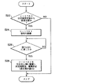
図7は、制御部200の第1の制御態様を説明するフローチャートである。この例は、図2に示すような巻取りばね114を内蔵しないタイプの巻取装置において、シートベルト装着の際に、緊急の際の乗員拘束に要する巻取り時間を考慮した所定量の弛みを予め設定する。
FIG. 7 is a flowchart for explaining a first control mode of the
CPU201は、メインプログラムを実行することにより、シートベルトの着用フラグを周期的に監視する(S22)。そして、前回の着用フラグがオフで、今回の着用フラグがオンであると、すなわち、乗員がシートベルトを引出してシートベルトを装着すると(S22;YES)、シートベルトの巻取り方向にモータ110を駆動する(S24)。CPU201はモータの電流値によって把握されるベルト張力Fの値を監視する(S26;NO)。張力Fが、予め定められた、乗員を拘束したシートベルトの弛みのない状態の張力F1に達すると(S26;YES)、モータ110を停止し、シートベルトの引き出し方向に駆動し、所定の弛み量d1を与える。例えば、シートベルトの20mmから30mm程度の引出しに相当する所定の時間だけモータ110を駆動する(S28)。この程度の弛みがあれば、乗員がベルト取付けによる違和感を感じない。また、乗員拘束に要する時間の許容範囲である。これよりも弛みが大きいと、ベルトがゆるくて乗員が不安感を持つ。また、衝突不可避と判断された場合に、ベルトをモータで巻取っても弛みの除去が不十分となる(間に合わない)。上記範囲よりも、弛みが少ない場合には、ベルトが身体に強く接触して違和感を生ずる可能性がある。弛み量d1を確保した後、本ルーチンを終了する。
The
図8は、図7に示した第1の制御態様を実行した後に、車両衝突等の際の制御態様を説明するフローチャートである。 FIG. 8 is a flowchart illustrating a control mode in the event of a vehicle collision after the first control mode shown in FIG. 7 is executed.
CPU201は、シートベルト装着状態において(S32)、衝突回避不可能フラグが設定されると(S34;YES)、モータ110をベルト巻取り方向に駆動する。シートベルトには弛み量d1が確保されているので、モータの負荷は少なく、モータは高速回転し、ベルト巻取りを行う(S36)。同時に、アクチュエータ112を作動させ、シートベルトロック機構102にロックをかけ、シートベルトが引出されるのを防止する(S38)。前述したように、シートベルトロック機構102はベルト引き出しは阻止するが、ベルト巻取りは妨げない。その後本ルーチンを終了する。シートベルト未装着状態(S32;NO)や、衝突回避可能状態(S34;NO)では、本ルーチンは行わない。
When the collision avoidance impossible flag is set in the seat belt wearing state (S32) (S34; YES), the
このように、シートベルトの所定量の弛みが確保された状態で衝突回避が不可能な状態が発生すると、ベルト巻取り方向にモータが高速で回転可能である。その結果、ベルトの弛みを除いた状態(巻取り量の最大)で乗員拘束が行われ、乗員の安全が図られる。 As described above, when a state where collision avoidance is impossible with a predetermined amount of slack in the seat belt secured, the motor can rotate at high speed in the belt winding direction. As a result, occupant restraint is performed in a state where the slack of the belt is removed (maximum winding amount), and occupant safety is achieved.
図9は、所要の弛み量d1を維持するための制御態様を示すフローチャートである。上述した図8の制御によってシートベルトの所要の弛み量d1が確保される。しかしながら、乗員の動きが大きかったり、乗員がシートベルトを引出したりした場合には、弛み量は所要のd1の範囲には維持されず、図8におけるシートベルト巻取りにおいて弛みが十分に除かれないことが考えられる。 FIG. 9 is a flowchart showing a control mode for maintaining the required amount of slack d1. The required amount of slack d1 of the seat belt is secured by the control shown in FIG. However, when the occupant moves greatly or the occupant pulls out the seat belt, the amount of slack is not maintained within the required range of d1, and the slack is not sufficiently removed in the winding of the seat belt in FIG. It is possible.
そこで、図9に示すように、CPU201は、シートベルト装着フラグを監視し、シートベルトを装着していると(S42;Yes)、周期的に、シートベルトの引き出し量を読込み(S44)、シートベルトの弛みが、弛み量d1の範囲内にあるかどうかを判別する(S46)。弛み量d1の範囲内にある場合には(S46;YES)、弛み量d1は維持(確保)されているので、本ルーチンを終了する。弛み量d1の範囲内にない場合には(S46;NO)、シートベルトの弛みを弛み量d1に設定するべく、モータ110をベルト巻取り方向あるいは引き出し方向に駆動する(S48)。引き出し量の読込み、比較、モータ駆動を繰返して(S44〜S48)、シートベルトの弛みを弛み量d1に設定する。設定後、本ルーチンを終了する。
Therefore, as shown in FIG. 9, the
このようにして、シートベルトの所要の弛み量d1を一定に維持することが可能である。 In this way, the required slack amount d1 of the seat belt can be kept constant.
図10は、制御部200の第2の制御態様を説明するフローチャートである。この例は、図3に示すような巻取りばね114を内蔵するタイプの巻取装置、すなわち、シートベルトの余分な弛みが巻取りばね114の弱いテンションによって除去されるタイプのベルト巻取装置において、緊急の際の乗員拘束に要する巻取り時間を短縮せんとするものである。このため、モータを暫時ベルト引き出し方向に駆動してベルトを所要の弛み量d1だけ弛ませた後、モータをベルト巻取り方向に駆動してベルトの巻取りを開始する。
FIG. 10 is a flowchart for explaining a second control mode of the
図10において、CPU201は、シートベルトが装着されていると(S52;YES)、周期的に衝突回避不可能フラグが設定されたかどうかを判別する(S54)。衝突回避不可能フラグが設定されない場合には(S54;NO)、本ルーチンを終了する。衝突回避不可能フラグが設定された場合には(S54;YES)、一旦、モータ110をシートベルトの引き出し方向に暫時駆動し、所要の弛み量d1を与える(S56)。その後、モータ110をシートベルトの巻取り方向に駆動する(S58)。同時に、アクチュエータ112を作動させてシートベルトロック機構102を強制的にロック状態とする。ロック状態でも、ベルトの巻取りは可能である(S60)。これにより、最大限のシートベルト巻取りが可能となり、乗員は座席に拘束される。
In FIG. 10, when the seat belt is worn (S52; YES), the
CPU201は、シートベルトが非装着である場合には(S52;NO)、シートベルトロック機構のロックを解除し(S62)、モータ110の巻取り駆動も停止する(S64)。モータ110の駆動が停止すると、巻取りばね114による巻取りによってシートベルトは巻取装置100に格納される。
When the seat belt is not attached (S52; NO), the
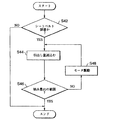
図11は、制御部200の第3の制御態様を説明するフローチャートである。この例は、図3に示すような巻取りばね114を内蔵するタイプの巻取装置、すなわち、シートベルトの余分な弛みを巻取りばね114の弱いテンションによって除去するタイプのベルト巻取装置において、緊急の際の乗員拘束に要する巻取り時間を短縮せんとするものである。このため、現在のシートベルトの弛み量を判別し、その結果に応じて、ベルトの巻取りを直ちに行うか、一旦ベルトを所定量弛ませた後、ベルトの巻取りを行うかを選択する。
FIG. 11 is a flowchart for explaining a third control mode of the
図11において、CPU201は、シートベルト装着フラグのオン状態において(S72;YES)、周期的に、「衝突可避フラグ」、「衝突不可避フラグ」を監視する。「衝突可避フラグ」がオン状態で(S74;YES)、「衝突不可避フラグ」がオフ状態であると(S76;NO)、衝突の可能性があるので、シートベルトの巻取りを行い(S78)、ベルトの張力が所定値F1に達するまで、ベルトの巻取りを行う(S80)。張力が所定値F1になると(S80;YES)、シートベルトを引き出し側に駆動する。所定時間後、モータ110を停止し、シートベルトに弛み量d1を設定する。そして、モータ110に巻取りばね114に抗してベルト弛み量d1を維持する力を発生する電流を供給する(S82)。なお、図9に示すような弛み量d1を維持するフィードバック制御を行っても良い。
In FIG. 11, the
所要の弛み量を維持することにより、車両の衝突が不可避となったときには、モータの負荷の少ない状態から直ちにベルトの巻取りを開始することが出来るようになる。 By maintaining the required amount of slack, when a vehicle collision becomes inevitable, the winding of the belt can be started immediately from a state where the motor load is low.
「衝突可避フラグ」がオン状態で(S74;YES)、「衝突不可避フラグ」もオン状態であると(S76;YES)、CPU201は、現在のシートベルトの弛み量をRAM203の弛み量エリアから読出し、弛み量は所定値d1以上あるかどうかを判別する(S84)。
When the “collision unavoidable flag” is on (S74; YES) and the “collision unavoidable flag” is also on (S76; YES), the
弛みが所定値d1以上あるときは(S84;YES)、直ちに、シートベルトの巻取りを行い(S86)、同時にシートベルトロック機構を作動させる(S88)。これにより、モータが高速回転してベルトを巻取り、ベルトに弛みのない状態で乗員が座席に拘束される。 When the slack is equal to or greater than the predetermined value d1 (S84; YES), the seat belt is immediately wound (S86), and at the same time, the seat belt lock mechanism is activated (S88). As a result, the motor rotates at high speed to wind the belt, and the occupant is restrained by the seat in a state where the belt is not slack.
弛みが所定値d1以上ないときは(S84;NO)、一旦、シートベルトを引き出し側に駆動して、所定の弛み量d1を確保する(S90)。その後、シートベルトの巻取りを行い(S86)、同時にシートベルトロック機構を作動させる(S88)。これにより、モータが高負荷状態から起動することが回避され、回転速度が上がってからベルトを巻取る。小型のモータでもベルトの巻取りを素早く行うことが可能である。 When the slack does not exceed the predetermined value d1 (S84; NO), the seat belt is once driven to the pull-out side to secure a predetermined slack amount d1 (S90). Thereafter, the seat belt is wound up (S86), and at the same time, the seat belt lock mechanism is operated (S88). As a result, the motor is prevented from starting from a high load state, and the belt is wound after the rotational speed is increased. Even a small motor can take up the belt quickly.
シートベルトの非装着の場合(S72;NO)、あいるは衝突の可能性がない場合(S74;NO)には、シートベルトの引き出しロックは解除され(S92)、ベルトの巻取り駆動も停止される(S94)。モータの駆動が停止すると、巻取りばね114による巻取りにより、非装着のシートベルトは巻取装置100に格納される。シートベルトを装着している場合には、巻取りばね114による弱い張力によってベルトの弛みは除去される。
If the seat belt is not attached (S72; NO), or if there is no possibility of collision (S74; NO), the seat belt drawer lock is released (S92), and the belt winding drive is also stopped. (S94). When the drive of the motor is stopped, the unmounted seat belt is stored in the winding
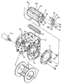
図12乃至図23は、巻取り部100の、主に、シートベルトロック機構(リールの機械的ロック機構、シートベルト加速度感知手段、車両減速度感知手段)120と電磁的アクチュエータ112を説明する分解斜視図及び要部縦断面図である。なお、図12には、プリテンショナは取付けられていない。車両特性上必要ならば、図2に示したように、図12のリトラクタベース1と動力伝達ユニット15との間にプリテンショナを設置する。
12 to 23 are exploded views for explaining the seat belt lock mechanism (reel mechanical lock mechanism, seat belt acceleration sensing means, vehicle deceleration sensing means) 120 and the
図12乃至図17において、リトラクタベース1はその大部分がコの字状断面を有しており、対向する側板1a,1bには対向してそれぞれ巻取軸貫通穴が穿設され、シートベルト302(図示せず)を巻装する巻取軸であるリール3がこれら巻取軸貫通穴を挿通した状態で回動自在に軸架されている。
12 to 17, most of the
側板1aに設けられた巻取軸貫通穴の内周縁には係合内歯2が形成されており、該巻取軸貫通穴の外側にはリング部材4が並設されている。リング部材4には内周縁に沿って絞り加工が施されており、リング部材4が側板1aの外側面にリベット40によって固着された際に、係合内歯2とリング部材4の内周縁との間に軸方向の隙間が生じるように構成されている。
Engagement
そして、ベース1の側板1a側には、緊急時にシートベルトの引き出しを阻止するための緊急ロック機構が配置されている。又、ベース1の側板1b側には、図示しない、タイミングベルト107を介して電動モータ110によって駆動される軸15c(リール軸103a相当する)に連結したプーリ105、ポテンショメータ111などを含む動力伝達ユニット15が配置されている。リール3は、アルミニウム合金等で一体成形された略円筒形の巻取軸であり、シートベルトが巻回される胴部28には、シートベルト端部を挿通させて保持するため直径方向に貫通するスリット開口28aが設けられている。又、リール3の外周部には別体で形成されたフランジ部材13が装着され、シートベルトの巻乱れを防止する。又、リトラクタベース1に組み付けたリール3の外周に巻装されたシートベルトは、リトラクタベース1の背板側の上部に取り付けられたシートベルトガイド41を挿通させることによって、出入り位置が規制される。
An emergency lock mechanism is provided on the
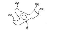
リール3の両端面にはリール3を回転自在に支持する為の回転支軸が突設されるが、リール3のセンサー側端面には別体に構成された支軸ピン6が回転支軸として圧入されている。又、リール3のセンサー側端面には、側板1aに構成された係合内歯2に係合可能なロック部材であるポール16を揺動回動可能に軸支する支軸7が突設されている。また、ポール16が係合内歯2と係合する方向へ揺動回転した時に、ポール16の揺動側端部と反対側のポール後端部16eを位置決めし、係合内歯2との間でポール16に大きな荷重が加わった場合にはその荷重を受ける受圧面45が、リール3のセンサー側端面に設けられている。
Rotating support shafts for rotatably supporting the
更に、リール3のセンサー側端面には、後述するロック作動手段のラッチ部材であるラチェットホイール18に揺動可能に軸支された揺動レバー部材20の反時計回り方向の回転を規制する為の係止突起8が設けられている。凹部9は、ラチェットホイール18をシートベルト引出し方向(図13中、矢印X2 方向)に回転付勢する引張りコイルバネ36と、後述するセンサースプリング25を押圧するロックアーム26のアーム部26cとがリール3に干渉するのを防ぐ逃げである。
Further, on the sensor side end surface of the
ポール16の揺動端部には、側板1aに構成された係合内歯2に対応して係合可能な係合歯16cが一体形成されている。又、ポール16の中央部には、支軸7に遊嵌する軸穴16aが貫設されており、ポール16のセンサー側面には、揺動端側に位置する係合突起16bとポール後端部16e側に位置する押圧突起16dとが突設されている。
Engaging teeth 16c that can be engaged with the engaging
即ち、軸穴16aは支軸7に対して遊嵌状態なので、ポール16が支軸7に対して揺動回動可能及び所定量相対移動可能に軸支されている。又、リール3に圧入された支軸ピン6により貫通孔17aを嵌通された保持プレート17の係止孔17bには、ポール16の軸穴16aを貫通した支軸7の先端が加締められており、保持プレート17はリール3の端面からポール16が浮き上がるのを防止している。
That is, since the
そして、ポール16の係合突起16bの端部は、保持プレート17の外側に配設されて支軸ピン6に回動自在に軸支されたラチェットホイール18に形成されているカム穴18aに挿入されている。そこで、ラチェットホイール18がリール3に対してシートベルト巻取方向(図13中矢印X1 方向)に相対回転すると、カム穴18aが係合突起16bの端部をリール3の回転中心軸から半径方向外方に移動させるように作用するので、ポール16は側板1aに構成された係合内歯2との係合方向(図12中矢印Y1 方向)へ支軸7を中心に揺動回転させられる。
The end of the
即ち、ポール16が、係合内歯2と係合する方向に揺動回転させられ、ポール16の係合歯16cが係合内歯2に係合することによってリール3のシートベルト引出し方向の回転を阻止するロック手段を構成している。ラチェットホイール18は、中心穴が支軸ピン6に回動自在に軸支された爪車であり、その外周部には車体加速度感知手段51のセンサーアーム53と係合するためのラチェット歯18bが形成されている。更に、支軸ピン6のフランジ部6aは、シートベルトの引出し加速度を感知する慣性感知手段であるシートベルト加速度感知手段を構成する為の円盤状の慣性部材であるイナーシャプレート30の中心穴30aを軸支している。ラチェットホイール18の中心穴周縁で巻取装置外側に向かって突設された係止爪部23は、係合穴30bに係合してイナーシャプレート30のスラスト方向の位置決めを行っている。ラチェットホイール18に形成された長穴24にはイナーシャプレート30の係合突出部31が係合しており、長穴24の一端縁24aが緊急ロック機構非作動時のイナーシャプレート30の回転方向の位置決めを行っている(図15参照)。
That is, the
ラチェットホイール18の外側面には、図15に示すように、ロックアーム26を回動自在に軸支する軸部22と、ばねフック部55とが突設されている。そして、図17に示すように、イナーシャプレート30には、ばねフック部55を挿通させる開口56が形成されている。この開口56は、ばねフック部55を挿通した状態でイナーシャプレート30がラチェットホイール18に対して相対回転可能な長穴状に形成されており、その一端には、ばねフック部55に対応するばねフック部57が装備されている。
As shown in FIG. 15, a
そして、これらの一対のばねフック部55,57間には、圧縮コイルばね58が嵌挿される。この圧縮コイルばね58は、図18に示すように、イナーシャプレート30上の係合突出部31が、ラチェットホイール18に形成された長穴24の他端縁24bに当接した状態(即ち、非ロック状態)に保たれるように、付勢している。
A
ラチェットホイール18の内側面には、一端が保持プレート17の掛止部17cに掛止された引張りコイルバネ36の他端を掛止するばね掛止部21が設けられており、引張りコイルバネ36はリール3に対してラチェットホイール18をシートベルト引出し方向(矢印X2 方向)に回転付勢している。図16に示したように、ロックアーム26には、ギアケース34の内歯ギア34aと噛み合い可能な係合爪26bと、ラチェットホイール18の外側面に設けられた一対のフック部18dに両端を支持された線状のセンサースプリング25の長手方向中央部を押圧するアーム部26cとが設けられている。
On the inner side surface of the
そこで、ロックアーム26は、係合爪26bが被係合部である内歯ギア34aと噛み合ってラチェットホイール18のシートベルト引出し方向の回転を阻止する係止部材を構成している。そして、係合爪26bは、センサースプリング25の付勢力により、イナーシャプレート30の当接部32に押圧付勢されている。尚、アーム部26cの揺動範囲に対応するラチェットホイール18には開口が形成され、アーム部26cが開口を貫通するが、これはセンサースプリング25に対するアーム部26cの係合状態を保証するためのものである。
Therefore, the
当接部32は、ロックアーム26の係合爪26bの背部26dが摺接するカム面として、イナーシャプレート30の回転がロックアーム26に影響を与えない第1のカム面32aと、リール3に対するイナーシャプレート30の回転遅れに応じて係合爪26bが内歯ギア34aに噛合するようにロックアーム26を揺動させる第2のカム面32bとを具備した構成とされている。
The
緊急ロック機構の非ロック状態では、第1のカム面32aがロックアーム26の背部26dに当接しており、イナーシャプレート30のリール3に対する回転遅れが一定量を超えるまでは、背部26dが第2のカム面32bに当接しないようになっている。第1のカム面32aの長さ(即ち、第1のカム面32aに背部26dが摺接した状態でイナーシャプレート30が回転する量)は、シートベルトの全量格納時にイナーシャプレート30に作用する慣性力で、イナーシャプレート30がリール3に対して回転遅れを生じても、その程度の回転遅れでは、ロックアーム26の背部26dが第2のカム面32bには到達しない程度に、第1のカム面32aの長さが設定されている。
In the unlocked state of the emergency lock mechanism, the
また、本実施形態におけるロックアーム26は、係合爪26bとは反対側の揺動端に当接爪26eが形成されている。そして、この当接爪26eに対応するように、イナーシャプレート30には、当接爪26eが当接可能な段差部33が設けられている。段差部33は、非ロック状態でイナーシャプレート30が初期位置にある時、当接爪26eが当接することで、ロックアーム26のロック方向への回動を規制するものである。図19及び図20に示すように、イナーシャプレート30が所定量以上回転遅れを生じ、ロックアーム26の背部26dが第2のカム面32bに当接する時には、第2のカム面32bによる押圧作用によってロックアーム26がロック方向へ揺動可能になる。
Further, the
更に、ラチェットホイール18の内側面に突設された支軸19には、軸孔20aを軸支された揺動レバー部材20が揺動可能に配設されている。揺動レバー部材20は、リール3のセンサー側端面に突設された係止突起8により反時計回り方向の回転が適宜規制されると共に、ポール16のセンサー側面に突設された押圧突起16dが支軸19と係止突起8との間に当接することによって時計回り方向の回転が適宜規制されるように、リール3とラチェットホイール18との間に組付けられている。
Further, a swing lever member 20 pivotally supported by a
そして、イナーシャプレート30の外側に配設されたギヤケース34の中心部には、支軸ピン6を介してリール3を回転自在に軸支する軸支部34bが設けられており、軸支部34bの底面には支軸ピン6の鍔部6aが当接し、リール3の軸線方向の位置決め面となっている。更に、ギヤケース34の下部には、車体の加速度を感知する慣性感知手段である車体加速度感知手段51を格納する箱形の格納部50が設けられている。
A
そして、ギヤケース34を覆う側板1aの外側には、センサーカバー35が配設される。次に、上記シートベルト用巻取装置の作動について説明する。まず、通常使用状態は、図18に示すように、ラチェットホイール18は、ばね掛止部21とプレート17の掛止部17cに掛止された引張りコイルばね36の付勢力によって、リール3に対してシートベルト引出し方向(図中の矢印X2方向)に付勢されており、カム穴18aに係合突起16bが係合するポール16を係合内歯2と非係合な方向に付勢している。そのため、リール3は回転可能であり、シートベルトの引出しは自在である。
A
しかして、衝突等の緊急時にイナーシャプレート30を含むシートベルト加速度感知手段又は車体加速度感知手段51が作動すると、上記ロック作動手段のシートベルト引出し方向の回転を阻止する係止手段であるロックアーム26又はセンサーアーム53がラチェットホイール18のシートベルト引出し方向の回転を阻止して、巻取装置のロック手段を作動させる。
Thus, when the seat belt acceleration sensing means including the
そして、車体加速度感知手段51又はシートベルト加速度感知手段が作動し、ラチェットホイール18のシートベルト引出し方向の回転が阻止された後、更にシートベルトが巻取装置から引出されると、ラチェットホイール18はリール3に対して回転遅れを生じ、シートベルト巻取方向(矢印X1方向)に相対回転するので、ラチェットホイール18のカム穴18aがポール16の係合突起16bをリール3の回転中心軸から半径方向外方に移動させていく。そこで、ポール16は支軸7を中心に係合内歯2との係合方向(図12中、矢印Y1 方向)へ揺動回転させられる。
Then, after the vehicle body acceleration sensing means 51 or the seat belt acceleration sensing means is actuated and the rotation of the
更に、シートベルトが巻取装置から引出されると、ポール16の係合歯16cが係合内歯2に噛み合い完了となる。そしてこの状態では、ポール16のポール後端部16eとリール3の受圧面45との間には隙間があり、揺動レバー部材20はリール3の係止突起8とポール16の押圧突起16dとによってほぼ遊び無く回転が規制されている。
Further, when the seat belt is pulled out from the winding device, the engagement teeth 16c of the
ここで、ポール16の軸穴16aは、リール3の支軸7に対して遊嵌状態であり、リール3に対して揺動回動可能及び所定量相対移動可能に軸支されているので、その上さらに、シートベルトが巻取装置から引出されると、ポール後端部16eが受圧面45と当接するまで、ポール16はリール3の回転中心軸を中心にリール3に対して相対回転する。
Here, the
この時、ポール16の押圧突起16dは側板1aに対して不動の位置関係だが、リール3の係止突起8はシートベルト引出し方向(矢印X2 方向)に回転していく。この動きにより、揺動レバー部材20は、押圧突起16dとの接点を回動支点として係止突起8により揺動端部が押され、図13中時計回り方向へ揺動回転させられる。揺動レバー部材20が押圧突起16dとの接点を回動中心として図13中時計回り方向へ揺動回転すると、ラチェットホイール18の支軸19に軸支されている軸孔20aがリール3の回転中心軸に対しシートベルト巻取方向(矢印X1 方向)に回転することになる。その結果、ラチェットホイール18は、リール3に対してシートベルト巻取方向(矢印X1方向)に逆回転させられる。
At this time, the pressing protrusion 16d of the
従って、車体加速度感知手段51又はシートベルト加速度感知手段が作動して巻取装置のロック手段がリール3のシートベルト引出し方向の回転を阻止するロック状態でも、シートベルト引出し方向の回転が阻止されたラチェットホイール18は、車体加速度感知手段51におけるセンサーアーム53又はシートベルト加速度感知手段におけるロックアーム26をギヤケース34の内歯ギア34aとの係合から解除可能なフリー状態とすることができる。
Therefore, even when the vehicle body acceleration sensing means 51 or the seat belt acceleration sensing means is activated and the lock means of the winding device prevents the
ポール16のロック状態において、さらにシートベルトに大きな張力が作用すると、ギヤケース34の軸支部34b及び動力伝達ユニット15の軸15cを支持している部分が変形し、リール3は上方に移動しようとする。この移動は、リールに形成された当接面3a及び溝3bがそれぞれ係合内歯2および側板1b上の係合内歯62(図12参照)と当接することで阻止され、シートベルトに作用する張力をこれらの面で受け止める。
When a greater tension is applied to the seat belt in the locked state of the
車両が停止してシートベルトに作用されたテンションが解除された時には、既にラチェットホイール18とセンサーアーム53又はロックアーム26のギヤケース34の内歯ギア34aとの係合が解除されているので、ラチェットホイール18は引張りコイルばね36の付勢力によりリール3に対して矢印X2 方向に回動されるので、ラチェットホイール18のカム穴18aがポール16の係合突起16bをリール3の回転中心軸側に移動させていく。この時、シートベルトに作用する引出し方向のテンションは上述の通り解除され、リール3はシートベルト巻取方向(矢印X1 方向)に回転できるようになっているので、ポール16の係合歯16cの先端が係合内歯2の先端と干渉しない状態までリール3が矢印X1方向に回転すると、ポール16は、係合内歯2との係合を解除する方向に支軸7を中心に揺動回転させられ、リール3のロックが解除されてシートベルトの引き出しが自在とされる。
When the vehicle is stopped and the tension applied to the seat belt is released, the
次に、シートベルト引き出し状態から電動モータ110による巻取りが行われ、動力伝達機構15の回転力に従って急激にシートベルトが全量巻き取られた場合には、急停止したリール3に対して、シートベルト加速度感知手段の慣性部材であるイナーシャプレート30は、そのまま巻取り方向に回転するので、リール3に対し巻取り方向に進み回転し、リール3の引出し方向で見たときにリール3に対して回転遅れが発生する。しかし、ロックアーム26の係合爪26bをギヤケース34の内歯ギア34aに係合させる方向へ揺動させるイナーシャプレート30の当接部32には、イナーシャプレート30のリール3に対する回転遅れが所定量に達した後に係合爪26bを内歯ギア34a方向へ揺動させる為の2つのカム面32a,32bによって構成されており、リール3に対するイナーシャプレート30の回転遅れが所定量に達するまでは、係合爪26bが内歯ギア34aの係合方向に揺動することがない。
Next, when the seat belt is pulled out by the
本発明の実施の形態では、上述したように構成され、作動するロック機構に図12の下部に示すように、更に、電磁的アクチュエータ112が設けられる。電磁的アクチュエータ112は、図21及び図22に示すように、ソレノイド(励磁コイル)112a、コイルスプリング(弾性部材)112b、つば付のプランジャ(磁心)112c等によって構成され、車体加速度感知手段51の下部に配置される。
In the embodiment of the present invention, as shown in the lower part of FIG. 12, the
通常状態では、ソレノイド112aは励磁されている。この状態では、図21に示すように、プランジャ112cはボールウェイト54と接触せず、ロック機構51に影響を与えない。制御部200がシートベルトをロックするべく、ソレノイド112aの励磁を解除すると(S38等)、スプリング112bの付勢力によってプランジャ112cは持上げられる。プランジャ112cの先端は、センサカバー52底部の開口を通ってボールウェイト54を突上げる。ボールウェイト54が押上げられると、センサーアーム53を図中上方に移動し、その係止突起53aがラチェットホイール18のラチェット歯18bに噛合する。これにより、ラチェットホイール18のシートベルト引出し方向(図13の矢印X2方向)の回動が阻止される。シートベルトが引出されてリール3を引出し方向に回転すると、係止されたラチェットホイール18とリール3との回転差によってポール16がリール3の半径方向外側に移動し、フレーム1aの内歯2に噛合する。これにより、リール3の引出し方向への回転が阻止される。
In the normal state, the
この例では、ソレノイド112aに励磁電流を供給しているときに、ロック動作を行わず、励磁電流を遮断すると、ロック動作を行うようにしている。すなわち、低レベルの作動信号を供給することによってロック機構を作動させる。従って、シートベルト装置への電源が遮断された場合に、シートベルトのロックが行わるようにすることが出来る。
In this example, when the excitation current is supplied to the
図23は、電磁的アクチュエータ112の他の構成例を示している。この例では、電磁的アクチュエータは、フレームに取付けられたソレノイド112a、プランジャ112c、一端部でプランジャ112cと係合し、中央部を回転可能に軸支されたくの字型のレバー112d、レバー112dに図中時計方向の付勢力を与えるコイルスプリング112bによって構成される。レバー112dの爪部が移動してラチェットホイール18の歯面18bに接すると、ラチェットホイール18の回転を阻止してポール16とフレームの内歯2によるロック機構を作動させる。
FIG. 23 shows another configuration example of the
制御部200からソレノイド112aに励磁電流が供給されている通常状態では、ソレノイド112aがコイルスプリング112bに抗してプランジャ112cを引寄せ、プランジャ112cと一端部で回動自在に軸支されているレバー112dの他端の爪部はラチェットホイール18から離間している。従って、ロック機構は作動しない。
In a normal state in which an excitation current is supplied from the
次に、CPUが、シートベルトをロックするべく制御部200からの励磁電流の供給が断たれる(S38等)。コイルスプリング112bの付勢力によってプランジャ112cが図の下方に引出され、レバー112dを回動する。これにより、レバー112dの他端の爪部はラチェットホイールの歯18bと噛合(係合)し、ラチェットホイール18のシートベルト引出し方向への回転を阻止する。シートベルトが引出されてリール3を引出し方向に回転すると、係止されたラチェットホイール18とリール3との回転差によってポール16がリール3の半径方向外側に移動し、フレーム1aの内歯2に噛合する。これにより、リール3の引出し方向への回転が阻止され、ロックが完了する。
Next, the CPU cuts off the supply of excitation current from the
このように、本発明の実施の形態によれは、シートベルト装着の際に、モータ起動の際の回転上昇と、巻取り時間を考慮して定めたシートベルトの弛み分を装着したシートベルトに予め与えておき、緊急の際のベルト巻取り時間をより短くする。衝突前にシートベルトの弛みを除去して乗員の安全を図る。 As described above, according to the embodiment of the present invention, when the seat belt is mounted, the seat belt having the seat belt slack determined in consideration of the rotation increase at the time of starting the motor and the winding time is mounted. It is given in advance, and the belt winding time in case of emergency is shortened. Remove the slack of the seat belt before the collision to ensure occupant safety.
また、緊急の際に、シートベルトを引き出し側に暫時駆動した後に、シートベルトを巻取ることにより、モータの起動負荷を少なくし、モータを直ちに高速回転させてベルトの巻取り時間を短縮する。 In an emergency, after the seat belt is driven to the pull-out side for a while, the seat belt is wound up to reduce the starting load of the motor, and the motor is immediately rotated at a high speed to shorten the belt winding time.
また、危険を予測したときに、シートベルトに所要の弛み量を確保してこれを維持し、更に衝突が不可避となったときに直ちにシートベルトの巻取りを行う。 Further, when a danger is predicted, a necessary amount of slack is secured and maintained in the seat belt, and when the collision becomes inevitable, the seat belt is immediately wound.
また、緊急の際には、弛み量が所定量あるかどうかを判断し、所定量ある場合には、直ちにベルト巻取りを開始する。所定量ない場合には、一旦、ベルトに所定量の弛みを与えた後、ベルトの巻取りを行って、短時間でシートベルトの弛みを除去する。 In an emergency, it is determined whether or not the slack amount is a predetermined amount. If there is a predetermined amount, the belt winding is immediately started. If there is no predetermined amount, a predetermined amount of slack is given to the belt, and then the belt is wound to remove the slack of the seat belt in a short time.
なお、上記実施形態では、シートベルト加速度感知手段と共に車体加速度感知手段を備えたタイプの緊急ロック機構について述べたが、本発明のシートベルト装置では、シートベルト加速度感知手段のみ、あるいは加速度感知手段のみを備えたタイプの緊急ロック機構を有する巻取装置でも良いことは勿論である。 In the above embodiment, the emergency lock mechanism including the vehicle body acceleration sensing means as well as the seat belt acceleration sensing means has been described. However, in the seat belt device of the present invention, only the seat belt acceleration sensing means or only the acceleration sensing means. Of course, a winding device having an emergency locking mechanism of the type provided with
また、実施例では、モータとして直流モータを使用したがこれに限定されず、各種方式のモータを使用することが可能である。 In the embodiment, a DC motor is used as a motor, but the present invention is not limited to this, and various types of motors can be used.
また、モータに代えて、バックルを引込む手段、あるいはラップベルト固定部を引込む手段において、シートベルトの所要弛み量を調整することとしても良い。
以上説明したように、本発明のシートベルト装置においては、モータの起動の際にモータの回転数が急上昇するに必要な程度にシートベルトを弛ませて、モータの低負荷状態からシートベルトの巻取りを開始するので、高速回転でシートベルトが巻取られ、乗員の座席への拘束を素早く行うことが可能となる。また、シートベルトの弛みが短時間で除去出来れば、衝突の判断に割当てる時間を増やすことが出来るので具合が良い。
In addition, instead of the motor, the required slack amount of the seat belt may be adjusted by means of retracting the buckle or means of retracting the lap belt fixing portion.
As described above, in the seat belt device of the present invention, when the motor is started, the seat belt is loosened to the extent necessary for the motor speed to rapidly increase, and the seat belt is wound from the low load state of the motor. Since the seating is started, the seat belt is wound up at a high speed, and the passenger can be quickly restrained to the seat. Moreover, if the slack of the seat belt can be removed in a short time, it is possible to increase the time allocated to the determination of the collision, which is good.
100 シートベルト巻取装置
200 制御部
302 シートベルト
100
Claims (1)
Priority Applications (1)
| Application Number | Priority Date | Filing Date | Title |
|---|---|---|---|
| JP2009026044A JP4712098B2 (en) | 2009-02-06 | 2009-02-06 | Seat belt device |
Applications Claiming Priority (1)
| Application Number | Priority Date | Filing Date | Title |
|---|---|---|---|
| JP2009026044A JP4712098B2 (en) | 2009-02-06 | 2009-02-06 | Seat belt device |
Related Parent Applications (1)
| Application Number | Title | Priority Date | Filing Date |
|---|---|---|---|
| JP25070999A Division JP4480208B2 (en) | 1999-09-03 | 1999-09-03 | Seat belt device |
Publications (2)
| Publication Number | Publication Date |
|---|---|
| JP2009102012A true JP2009102012A (en) | 2009-05-14 |
| JP4712098B2 JP4712098B2 (en) | 2011-06-29 |
Family
ID=40704213
Family Applications (1)
| Application Number | Title | Priority Date | Filing Date |
|---|---|---|---|
| JP2009026044A Expired - Fee Related JP4712098B2 (en) | 2009-02-06 | 2009-02-06 | Seat belt device |
Country Status (1)
| Country | Link |
|---|---|
| JP (1) | JP4712098B2 (en) |
Cited By (3)
| Publication number | Priority date | Publication date | Assignee | Title |
|---|---|---|---|---|
| JP2011156921A (en) * | 2010-01-29 | 2011-08-18 | Tokai Rika Co Ltd | Webbing control device |
| CN102975684A (en) * | 2011-09-06 | 2013-03-20 | 现代自动车株式会社 | Seat belt pretensioner for vehicle and method for protecting passenger using the same |
| CN107284403A (en) * | 2017-05-27 | 2017-10-24 | 吉利汽车研究院(宁波)有限公司 | A kind of intelligent active belt control system |
Citations (11)
| Publication number | Priority date | Publication date | Assignee | Title |
|---|---|---|---|---|
| JPS5878845A (en) * | 1981-11-04 | 1983-05-12 | Nippon Soken Inc | Taking up device of seat belt |
| JPS5945243A (en) * | 1982-09-06 | 1984-03-14 | Nissan Motor Co Ltd | Seat belt retractor |
| JPS59114359U (en) * | 1983-01-24 | 1984-08-02 | 日産自動車株式会社 | Emergency locking retractor |
| JPS59192638A (en) * | 1983-04-14 | 1984-11-01 | Nissan Motor Co Ltd | Seat belt retractor |
| JPS62275861A (en) * | 1986-05-23 | 1987-11-30 | Ashimori Ind Co Ltd | Retractor for seat belt |
| JPH0365455A (en) * | 1989-08-01 | 1991-03-20 | Tokai Rika Co Ltd | Webbing take-up motion |
| JPH09132113A (en) * | 1995-09-08 | 1997-05-20 | Takata Kk | Occupant restricting protective system of vehicle |
| JPH09272401A (en) * | 1996-04-05 | 1997-10-21 | Takata Kk | Seat belt retractor using ultrasonic motor |
| JPH10167002A (en) * | 1996-12-16 | 1998-06-23 | Takata Kk | Seatbelt retractor |
| JPH10167003A (en) * | 1996-12-16 | 1998-06-23 | Takata Kk | Seatbelt retractor |
| JPH11198760A (en) * | 1998-01-08 | 1999-07-27 | Nippon Seiko Kk | Occupant restraint and crash protection device for vehicle |
-
2009
- 2009-02-06 JP JP2009026044A patent/JP4712098B2/en not_active Expired - Fee Related
Patent Citations (11)
| Publication number | Priority date | Publication date | Assignee | Title |
|---|---|---|---|---|
| JPS5878845A (en) * | 1981-11-04 | 1983-05-12 | Nippon Soken Inc | Taking up device of seat belt |
| JPS5945243A (en) * | 1982-09-06 | 1984-03-14 | Nissan Motor Co Ltd | Seat belt retractor |
| JPS59114359U (en) * | 1983-01-24 | 1984-08-02 | 日産自動車株式会社 | Emergency locking retractor |
| JPS59192638A (en) * | 1983-04-14 | 1984-11-01 | Nissan Motor Co Ltd | Seat belt retractor |
| JPS62275861A (en) * | 1986-05-23 | 1987-11-30 | Ashimori Ind Co Ltd | Retractor for seat belt |
| JPH0365455A (en) * | 1989-08-01 | 1991-03-20 | Tokai Rika Co Ltd | Webbing take-up motion |
| JPH09132113A (en) * | 1995-09-08 | 1997-05-20 | Takata Kk | Occupant restricting protective system of vehicle |
| JPH09272401A (en) * | 1996-04-05 | 1997-10-21 | Takata Kk | Seat belt retractor using ultrasonic motor |
| JPH10167002A (en) * | 1996-12-16 | 1998-06-23 | Takata Kk | Seatbelt retractor |
| JPH10167003A (en) * | 1996-12-16 | 1998-06-23 | Takata Kk | Seatbelt retractor |
| JPH11198760A (en) * | 1998-01-08 | 1999-07-27 | Nippon Seiko Kk | Occupant restraint and crash protection device for vehicle |
Cited By (4)
| Publication number | Priority date | Publication date | Assignee | Title |
|---|---|---|---|---|
| JP2011156921A (en) * | 2010-01-29 | 2011-08-18 | Tokai Rika Co Ltd | Webbing control device |
| CN102975684A (en) * | 2011-09-06 | 2013-03-20 | 现代自动车株式会社 | Seat belt pretensioner for vehicle and method for protecting passenger using the same |
| KR101305566B1 (en) * | 2011-09-06 | 2013-09-09 | 현대자동차주식회사 | Seat belt pretensioner for vehicle and method for passengers protection using pretensioner |
| CN107284403A (en) * | 2017-05-27 | 2017-10-24 | 吉利汽车研究院(宁波)有限公司 | A kind of intelligent active belt control system |
Also Published As
| Publication number | Publication date |
|---|---|
| JP4712098B2 (en) | 2011-06-29 |
Similar Documents
| Publication | Publication Date | Title |
|---|---|---|
| JP4667549B2 (en) | Seat belt device | |
| US7216827B2 (en) | Seatbelt retractor and seatbelt device | |
| EP1690757B1 (en) | Seat belt retractor, seat belt apparatus, and vehicle with a seat belt apparatus | |
| JP2006282015A (en) | Seat belt retractor, seat belt device, and vehicle therewith | |
| JP4489122B2 (en) | Vehicle seat belt device | |
| JP2006298142A (en) | Seat belt retractor, seat belt device, and vehicle with seat belt | |
| JP2006321358A (en) | Seat belt retractor, seat belt device, and vehicle with seat belt device | |
| JP2006290285A (en) | Seat belt retractor, seat belt device, and vehicle having the seat belt device | |
| JP2004262258A (en) | Occupant restraint safety device for vehicle | |
| JP4166788B2 (en) | Seat belt retractor | |
| JP4712098B2 (en) | Seat belt device | |
| JP4516172B2 (en) | Seat belt device | |
| JP4439633B2 (en) | Seat belt system | |
| EP1818225B1 (en) | Motor retractor | |
| JP4480208B2 (en) | Seat belt device | |
| JP2011111007A (en) | Seat belt retractor and seat belt device | |
| JP4414029B2 (en) | Seat belt device | |
| JP4146970B2 (en) | Seat belt device | |
| JP4617224B2 (en) | Seat belt device | |
| JP4128459B2 (en) | Vehicle occupant restraint protection device | |
| JP2009234581A (en) | Seat belt device | |
| JP2010111159A (en) | Webbing winding device | |
| JPH10244905A (en) | Webbing take-up device | |
| JP2006224954A (en) | Webbing winding device | |
| JP2019142437A (en) | Webbing take-up device |
Legal Events
| Date | Code | Title | Description |
|---|---|---|---|
| A521 | Written amendment |
Free format text: JAPANESE INTERMEDIATE CODE: A523 Effective date: 20090306 |
|
| A621 | Written request for application examination |
Free format text: JAPANESE INTERMEDIATE CODE: A621 Effective date: 20090306 |
|
| A131 | Notification of reasons for refusal |
Free format text: JAPANESE INTERMEDIATE CODE: A131 Effective date: 20090904 |
|
| A521 | Written amendment |
Free format text: JAPANESE INTERMEDIATE CODE: A523 Effective date: 20091029 |
|
| A131 | Notification of reasons for refusal |
Free format text: JAPANESE INTERMEDIATE CODE: A131 Effective date: 20100225 |
|
| A521 | Written amendment |
Free format text: JAPANESE INTERMEDIATE CODE: A523 Effective date: 20100408 |
|
| A131 | Notification of reasons for refusal |
Free format text: JAPANESE INTERMEDIATE CODE: A131 Effective date: 20100629 |
|
| A521 | Written amendment |
Free format text: JAPANESE INTERMEDIATE CODE: A523 Effective date: 20100803 |
|
| A01 | Written decision to grant a patent or to grant a registration (utility model) |
Free format text: JAPANESE INTERMEDIATE CODE: A01 Effective date: 20110228 |
|
| A61 | First payment of annual fees (during grant procedure) |
Free format text: JAPANESE INTERMEDIATE CODE: A61 Effective date: 20110322 |
|
| R250 | Receipt of annual fees |
Free format text: JAPANESE INTERMEDIATE CODE: R250 |
|
| R250 | Receipt of annual fees |
Free format text: JAPANESE INTERMEDIATE CODE: R250 |
|
| LAPS | Cancellation because of no payment of annual fees |