JP2009100893A - Cotton swab, its manufacturing method, and cotton swab article - Google Patents
Cotton swab, its manufacturing method, and cotton swab article Download PDFInfo
- Publication number
- JP2009100893A JP2009100893A JP2007274607A JP2007274607A JP2009100893A JP 2009100893 A JP2009100893 A JP 2009100893A JP 2007274607 A JP2007274607 A JP 2007274607A JP 2007274607 A JP2007274607 A JP 2007274607A JP 2009100893 A JP2009100893 A JP 2009100893A
- Authority
- JP
- Japan
- Prior art keywords
- shaft
- paper
- paper sheet
- pointing
- swab
- Prior art date
- Legal status (The legal status is an assumption and is not a legal conclusion. Google has not performed a legal analysis and makes no representation as to the accuracy of the status listed.)
- Ceased
Links
Images


Abstract
Description
本発明は、精密機器の清掃或いは耳垢の除去などに用いる綿棒及びその製造方法並びに綿棒品に関する。 The present invention relates to a cotton swab used for cleaning precision instruments or removing earwax, a method for producing the same, and a swab product.
従来、精密機器の清掃や耳垢の除去などに綿棒が用いられているが、精密機器の微細箇所の清掃に使用する綿棒や、幼児の耳垢などの除去に使用する綿棒では、その清掃部(いわゆる綿球)の径或いは太さを小さくすることが求められる。そのため、綿棒の清掃部を小さくすることが可能な綿棒が特許文献1で提案されている。特許文献1の綿棒は、原紙の全面に接着剤を塗布して巻き込んで紙軸が形成され、その紙軸の先端部が研削加工によって細径化され、細径化した紙軸の先端部に繊維を巻き付けて綿球が設けられている。前記綿棒は紙軸の先端部が細径化されているため、綿球を小さくすることが可能であると共に、研削されていない先端部以外の紙軸の径は太いため、軸の強度を維持することができる。 Traditionally, cotton swabs have been used to clean precision instruments and remove earwax, but the swabs used to clean minute parts of precision instruments and cotton swabs used to remove infant earwax, etc. It is required to reduce the diameter or thickness of the cotton ball). Therefore, Patent Document 1 proposes a cotton swab that can reduce the cleaning part of the cotton swab. The cotton swab of Patent Document 1 is formed by applying an adhesive to the entire surface of a base paper to form a paper shaft. The tip of the paper shaft is reduced in diameter by grinding, and the tip of the paper shaft is reduced in diameter. Cotton balls are provided by wrapping fibers. Since the tip of the cotton swab has a reduced diameter, the cotton ball can be made smaller, and the diameter of the paper shaft other than the unground tip is thick, so the strength of the shaft is maintained. can do.
ところで、上記特許文献1の綿棒は、径がそれ程太くない紙軸の先端部を研削ローラで加工して形成するものであるため、研削加工中に紙軸に折れや歪みが生じやすく、歩留まりが低くなりやすい。また、紙軸の先端部に微細な研削加工を施すため、製造コストも高価となる。また、指で摘む部分の目印がないため、例えば幼児の耳垢除去する場合に鼓膜を破ってしまう等、安全性を求められる使用方法には適さないという問題もある。 By the way, the cotton swab of the above-mentioned Patent Document 1 is formed by processing the tip of the paper shaft, which is not so thick, with a grinding roller, so that the paper shaft is likely to be broken or distorted during grinding, and the yield is high. It tends to be low. In addition, since the tip of the paper shaft is finely ground, the manufacturing cost is also expensive. Moreover, since there is no mark of the part picked with a finger | toe, there exists a problem that it is not suitable for the usage method as which safety | security is requested | required, for example, to tear the eardrum when removing the ear wax of an infant.
本発明は上記問題点に鑑み提案するものであって、低い製造コストで高い歩留まりを実現することが可能であると共に、安全性が求められる使用方法にも適する細い綿棒及びその製造方法並びに綿棒品を提供することを目的とする。 The present invention is proposed in view of the above-mentioned problems, and is capable of realizing a high yield at a low manufacturing cost, and is also suitable for a usage method that requires safety, a manufacturing method thereof, and a cotton swab product. The purpose is to provide.
本発明の綿棒は、直径が0.3mm〜3.0mmである軸部と、前記軸部と異なる色であり、前記軸部の一部の外周に固着して所定幅で周設される、厚さが0.3mm〜3.0mmの筒状の指摘み部と、前記軸部の少なくとも一端に設けられる清掃部とを備えることを特徴とする。前記指摘み部の幅方向の端辺は安全面から設定される基準位置に配設することが好ましい。 The cotton swab of the present invention has a shaft portion having a diameter of 0.3 mm to 3.0 mm and a color different from that of the shaft portion, and is fixed to a part of the outer periphery of the shaft portion and is provided with a predetermined width. A cylindrical pointing portion having a thickness of 0.3 mm to 3.0 mm and a cleaning portion provided at at least one end of the shaft portion are provided. It is preferable that the end in the width direction of the pointing portion is disposed at a reference position set from a safety aspect.
また、本発明の綿棒は、前記指摘み部が前記軸部の略中央の外周に所定幅で周設され、前記清掃部が前記軸部の両端に設けられていることを特徴とする。前記指摘み部の幅方向の両端辺は安全面から設定される基準位置に配設されていることが好ましい。 Moreover, the cotton swab of the present invention is characterized in that the pointing portion is provided with a predetermined width around the outer periphery of the substantially central portion of the shaft portion, and the cleaning portion is provided at both ends of the shaft portion. It is preferable that both end sides in the width direction of the pointing portion are disposed at reference positions set from a safety aspect.
また、本発明の綿棒は、前記指摘み部が、前記軸部と異なる色の紙シートを前記軸部の外周に巻回し、少なくとも、前記紙シートの内端縁を前記軸部に接着すると共に、前記紙シートの外端縁を前記紙シートに接着して形成されていることを特徴とする。更に、前記軸部が紙軸であり、前記紙軸が、紙軸用紙シートを巻き込み、少なくとも、前記紙軸用紙シートの外端縁を前記紙軸用紙シートに接着して形成され、前記指摘み部が、前記紙軸と同一素材で且つ異なる色の指摘み部用紙シートを前記紙軸の外周に巻回し、少なくとも、前記指摘み部用紙シートの内端縁を前記紙軸に接着すると共に、前記指摘み部用紙シートの外端縁を前記指摘み部用紙シートに接着して形成されている構成とすることが好ましい。 In the cotton swab of the present invention, the pointing portion winds a paper sheet of a color different from that of the shaft portion around the outer periphery of the shaft portion, and at least adheres the inner edge of the paper sheet to the shaft portion. The outer edge of the paper sheet is formed by adhering to the paper sheet. Further, the shaft portion is a paper shaft, and the paper shaft is formed by winding a paper shaft paper sheet and bonding at least an outer edge of the paper shaft paper sheet to the paper shaft paper sheet. The section is wound around the outer periphery of the paper shaft with the same material and different color pointing portion paper sheet as the paper shaft, and at least the inner edge of the pointing portion paper sheet is bonded to the paper shaft; It is preferable that the outer edge of the pointing portion paper sheet is formed by adhering to the pointing portion paper sheet.
また、本発明の綿棒の製造方法は、直径が0.3mm〜3.0mmである紙軸と、前記紙軸と異なる色であり、前記紙軸の一部の外周に接着して所定幅で周設される、厚さが0.3mm〜3.0mmの筒状の指摘み部と、前記紙軸の少なくとも一端に設けられる清掃部とを備える綿棒の製造方法であって、紙軸用紙シートの少なくとも外端縁に接着剤を塗布し、前記紙軸用紙シートを巻き込んで前記紙軸用紙シートの外端縁を前記紙軸用紙シートに接着し、紙軸を形成する第1工程と、少なくとも、前記紙軸の一部の外周と、前記紙軸用紙シートと同一素材で且つ異なる色の指摘み部用紙シートの外端縁とに接着剤を塗布し、前記指摘み部用紙シートを前記紙軸の外周に巻回し、前記指摘み部用紙シートの内端縁を前記紙軸に接着すると共に、前記指摘み部用紙シートの外端縁を前記指摘み部用紙シートに接着し、指摘み部を設ける第2工程と、前記指摘み部の幅方向と周方向に圧力が付加されるようにして、前記指摘み部を幅方向の両側から押圧し、前記押圧により前記指摘み部の幅方向両端辺の上端部にアール部を形成する第3工程と、前記指摘み部が設けられた前記紙軸の少なくとも一端に清掃部を設ける第4工程とを備えることを特徴とする。 The cotton swab manufacturing method of the present invention has a paper shaft having a diameter of 0.3 mm to 3.0 mm and a color different from that of the paper shaft, and is bonded to the outer periphery of a part of the paper shaft with a predetermined width. A cotton swab manufacturing method comprising a cylindrical pointing portion having a thickness of 0.3 mm to 3.0 mm provided around and a cleaning portion provided at at least one end of the paper shaft, the paper shaft paper sheet A first step of applying an adhesive to at least the outer edge of the paper, winding the paper shaft paper sheet, bonding the outer edge of the paper shaft paper sheet to the paper shaft paper sheet, and forming a paper shaft; An adhesive is applied to the outer periphery of a part of the paper shaft and the outer edge of the paper sheet sheet of the same material and different color as the paper shaft paper sheet; Wound around the outer periphery of the shaft, and glued the inner edge of the paper sheet sheet to the paper shaft A second step of adhering an outer edge of the pointing portion paper sheet to the pointing portion paper sheet and providing a pointing portion; and pressure is applied in the width direction and the circumferential direction of the pointing portion. A third step of pressing the pointing portion from both sides in the width direction, and forming a rounded portion at the upper end of both ends in the width direction of the pointing portion by the pressing, and the paper provided with the pointing portion And a fourth step of providing a cleaning portion at at least one end of the shaft.
また、本発明の綿棒品は、本発明の構成を有する第1の綿棒と、前記第1の綿棒の指摘み部と指摘み部の色が異なる、本発明の構成を有する第2の綿棒とを有し、前記第1の綿棒と前記第2の綿棒とを区分けして収容体に収容することを特徴とする。前記綿棒品は、第1、第2の綿棒に加え、第3、第4の綿棒を有するなど、指摘み部の色が異なる複数種類の綿棒を有するものとすることが可能である。 Further, the swab product of the present invention includes a first swab having the configuration of the present invention, and a second swab having the configuration of the present invention in which the color of the pointing portion and the pointing portion of the first cotton swab is different. The first cotton swab and the second cotton swab are separated and accommodated in a container. The swab product may have a plurality of types of swabs having different pointing portion colors such as third and fourth swabs in addition to the first and second swabs.
尚、本発明に於ける綿棒の清掃部は、綿繊維で形成されたものに限定されず、例えば天然繊維や合成繊維或いはウレタンゴム系材料など、綿棒状の清掃具として適用可能な範囲の各種の材料で形成することが可能である。また、筒状の指摘み部は上述の如く紙シートを巻き込んで形成すると好適であるが、予め形成された筒状の指摘み部を形成し、指摘み部の内周若しくは軸部の外周に接着剤を塗布し、指摘み部に軸部を挿入し、前記指摘み部を軸部の方へ押圧して形成する構成や、或いは軸部の外周に不織布等を押圧し、接着剤の接着若しくは溶着等で軸部の外周に指摘み部を形成する構成など適宜である。また、本発明に於ける軸部は、紙軸とすると好適であるが、プラスチック軸など適用可能な範囲の適宜の素材で形成することが可能である。また、紙軸用紙シートと指摘み部用紙シートは同一素材とすると好適であるが、異なる素材とすることも可能である。 In addition, the cleaning part of the cotton swab in the present invention is not limited to the one formed of cotton fiber, and various kinds in a range applicable as a cotton swab-shaped cleaning tool such as natural fiber, synthetic fiber or urethane rubber material, for example. It is possible to form with the material of. In addition, it is preferable that the cylindrical pointing portion is formed by winding a paper sheet as described above. However, a cylindrical pointing portion formed in advance is formed, and the cylindrical pointing portion is formed on the inner periphery of the pointing portion or the outer periphery of the shaft portion. Apply adhesive, insert the shaft part into the pointed part, press the pointed part toward the shaft part, or press the nonwoven fabric on the outer periphery of the shaft part to bond the adhesive Alternatively, a configuration in which the pointing portion is formed on the outer periphery of the shaft portion by welding or the like is appropriate. In addition, the shaft portion in the present invention is preferably a paper shaft, but it can be formed of an appropriate material within the applicable range such as a plastic shaft. In addition, the paper axis paper sheet and the pointing portion paper sheet are preferably made of the same material, but may be made of different materials.
また、本明細書開示の発明には、各発明や各実施形態の構成の他に、これらの部分的な構成を本明細書開示の他の構成に変更して特定したもの、或いはこれらの構成に本明細書開示の他の構成を付加して特定したもの、或いはこれらの部分的な構成を部分的な作用効果が得られる限度で削除して特定した上位概念化したものも含まれる。 In addition to the configurations of the inventions and embodiments, the invention disclosed in this specification includes those specified by changing these partial configurations to other configurations disclosed in this specification, or these configurations. To which other configurations disclosed in the present specification are added and specified, or those partial configurations that have been deleted and specified to the extent that partial effects can be obtained are included.
本発明は、軸部を全体に亘って細くし、軸部の端部に設ける清掃部の大きさを小さくすることができると共に、軸部の外周に筒状の指摘み部を設けることにより、軸部と指摘み部で構成される基部の所要強度を実現することができる。更に、軸部の外周に筒状の指摘み部を周設する構成により、細い軸部の先端に研削加工を行うことを不要にし、製造コストを低減することができると共に、高い歩留まりを実現することができる。また、筒状の指摘み部は、軸部を指で摘む際の安全上の基準領域に設けることが可能であり、安全性が求められる使用方法に適する綿棒とすることができる。更に、指摘み部は軸部と異なる色であることに加え、軸部の外周面と指摘み部の外周面との間に段差が形成されることから、視覚と触覚の双方の刺激により、利用者に指摘み部を摘むことを促すことが可能であり、安全性等を一層向上することができる。 The present invention can reduce the size of the cleaning portion provided at the end of the shaft portion by making the shaft portion thin throughout, and by providing a cylindrical pointing portion on the outer periphery of the shaft portion, The required strength of the base composed of the shaft portion and the pointing portion can be realized. Furthermore, the configuration in which the cylindrical pointing portion is provided on the outer periphery of the shaft portion eliminates the need for grinding the tip of the thin shaft portion, thereby reducing the manufacturing cost and realizing a high yield. be able to. Further, the cylindrical pointing portion can be provided in a safety reference region when the shaft portion is picked with a finger, and can be a cotton swab suitable for a usage method that requires safety. Furthermore, in addition to the color of the pointing portion being different from that of the shaft portion, a step is formed between the outer peripheral surface of the shaft portion and the outer peripheral surface of the pointing portion. It is possible to urge the user to pick the pointed portion, and safety and the like can be further improved.
また、紙シートを軸部の外周に巻回し接着して指摘み部を形成することにより、指摘み部を容易に製造することが可能となり、製造コストの低減、歩留まりの向上を図ることができる。好適には、軸部を紙シートを巻き込んだ紙軸とし、その紙軸と同一素材で指摘み部を形成することにより、共通する素材を用い、共通する製造設備を利用して指摘み部を形成することができる。そのため、製造の容易化、製造コストの低減を一層図ることができる。 Further, by forming a pointing portion by winding and bonding a paper sheet around the outer periphery of the shaft portion, it is possible to easily manufacture the pointing portion, thereby reducing the manufacturing cost and improving the yield. . Preferably, the shaft portion is a paper shaft around which a paper sheet is wound, and the pointing portion is formed of the same material as the paper shaft, so that a common material is used and the pointing portion is made using a common manufacturing facility. Can be formed. Therefore, it is possible to further facilitate manufacturing and reduce manufacturing costs.
また、指摘み部の幅方向と周方向に圧力が付加されるようにして、指摘み部を幅方向の両側から押圧し、前記押圧により指摘み部の幅方向両端辺の上端部にアール部を形成する工程を用いることにより、指摘み部の一体性の強化と、指摘み部の軸部に対する固着強度を高めることができる。また、指摘み部を指摘み部用紙シートの外周に巻回した場合に生ずる蛇行による出っ張りを除去し、仕上がりを綺麗にすることができる。 Further, pressure is applied to both the width direction and the circumferential direction of the pointing portion, the pointing portion is pressed from both sides in the width direction, and the rounded portion is formed at the upper end portion of both ends of the pointing portion in the width direction by the pressing. By using the step of forming, the integrity of the pointing portion and the fixing strength of the pointing portion to the shaft portion can be increased. Further, the protrusion due to meandering generated when the pointing portion is wound around the outer periphery of the pointing portion paper sheet can be removed, and the finish can be made beautiful.
また、指摘み部の色が異なる綿棒を区分けして収容体に収容する綿棒品とすることにより、複数の用途のそれぞれに適する綿棒をまとめて利用者に提供することが可能となる。更に、利用者は、例えば精密機械のA箇所を清掃する綿棒とA箇所と異なるB箇所を清掃する綿棒を区別する等、又は1〜2歳児用の綿棒と3〜4歳児用の綿棒を区別する等、各用途に適する綿棒を一見して認識することができ、特定の用途に適する綿棒を確実に使用することができる。 Moreover, by classifying the cotton swabs having different colors of the pointing portions into the cotton swabs accommodated in the container, it is possible to provide the user with the swabs suitable for each of a plurality of uses. Furthermore, the user distinguishes, for example, a cotton swab for cleaning the A portion of a precision machine and a cotton swab for cleaning a B portion different from the A location, or distinguishes a swab for a 1-2 year old child from a swab for a 3-4 year old child. For example, a swab suitable for each application can be recognized at a glance, and a swab suitable for a specific application can be reliably used.
本発明に係る実施形態の綿棒について説明する。 A cotton swab according to an embodiment of the present invention will be described.
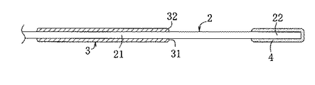
本実施形態の綿棒1は、図1〜図3に示すように、軸部2と、軸部2の外周に周設されている筒状の指摘み部3と、軸部2の両端に設けられている清掃部4とで構成され、指摘み部3と清掃部4との間で軸部2が露出している。軸部2は紙軸であり、矩形の紙軸用紙シートの外端縁に接着剤を塗布し、前記紙軸用紙シートを巻き込んで、前記紙軸用紙シートの外端縁を前記紙軸用紙シートに接着して形成されている。本例の軸部2の直径は1.5mmであるが、0.3mm〜3.0mmの範囲で適宜の直径とすることが可能である。
As shown in FIGS. 1 to 3, the cotton swab 1 of this embodiment is provided at both ends of the
筒状の指摘み部3は、軸部2と異なる色の紙製であり、軸部2の中央部21の外周に所定幅で周設されている。指摘み部3の厚さは、本例では0.55mm〜0.60mmとしているが、0.3mm〜3.0mmの範囲、好ましくは0.5〜2.0mm、より好ましくは0.5〜1.0mmの範囲で適宜の厚さとすることが可能である。指摘み部3の幅方向の両端辺31・31の上端部にはアール部32が形成されている。
The
指摘み部3は、軸部2と異なる色の矩形帯状の指摘み部用紙シート34を軸部2の外周に巻回し、指摘み部用紙シート34の内端縁341を軸部2に接着すると共に、指摘み部用紙シート34の外端縁342を指摘み部用紙シート34に接着して形成されており(図4参照)、図3の第1層331〜第7層337の様に、指摘み部用紙シート34が積層して指摘み部3を構成している。尚、指摘み部用紙シート34の素材には適用可能な範囲で適宜のものを用いることが可能であるが、水溶性接着剤の浸透性に優れて裏抜け(ストライクスルー)する紙とすると、外端縁342など一部に塗布した接着剤が、積層されている紙層のうち直接接着剤の塗布がない層間にも浸透し、固着強度及び一体化を高めることができて好適である。
The pointing
清掃部4は、指摘み部3が周設されている中央部21から所定距離離間して位置する先端部22を包むように設けられており、綿繊維等の繊維を先端部22に巻き付けて接着することにより構成されている。清掃部4の外径は必要に応じて適宜設定することが可能であるが、0.5mm〜3.2mm程度とすると好ましい。尚、清掃部4は、繊維で構成する以外にも、用途等に応じてウレタンゴム系材料とするなど適宜である。
The
上記実施形態の綿棒1を製造する際には、先ず、水溶性接着剤が裏抜け可能な紙軸用紙シートを用い、前記紙軸用紙シートの内面の外端縁に水溶性接着剤を塗布し、前記紙軸用紙シートを巻き込んで前記紙軸用紙シートに接着し、紙軸である軸部2を形成する。前記紙軸の形成では、巻き込みで積層される紙層のうち直接水溶性接着剤の塗布がない層間にも裏抜けで水溶性接着剤が浸透し、紙軸の固着強度や一体性を強化することができる。尚、前記構成に代え、特許文献1の如く、紙軸用紙シートの内面の全面に接着剤を塗布し、その紙軸用紙シートを巻き込んで接着することにより、紙軸を形成するようにすることも可能である。
When manufacturing the swab 1 of the above embodiment, first, a paper shaft paper sheet through which the water-soluble adhesive can be penetrated is used, and the water-soluble adhesive is applied to the outer edge of the inner surface of the paper shaft paper sheet. The paper axis paper sheet is rolled up and adhered to the paper axis paper sheet to form the
次いで、図4に示すように、紙軸用紙シートと同一素材で且つ紙軸用紙シートと色が異なる、水溶性接着剤が裏抜け可能な所定幅の指摘み部用紙シート34を用い、指摘み部用紙シート34の内面の外端縁342に水溶性接着剤を塗布すると共に、紙軸である軸部2の中央部21の外周に水溶性接着剤を塗布する。そして、指摘み部用紙シート34を張った状態に設け、軸部2を回転するようにして指摘み部用紙シート34を軸部2で巻き込み、指摘み部用紙シート34を軸部2の中央部21の外周に巻回する。前記工程により、指摘み部用紙シート34の内端縁341を軸部2の中央部21の外周に接着すると共に、指摘み部用紙シート34の外端縁342を指摘み部用紙シート34の内層に接着し、筒状の指摘み部3を設ける。前記指摘み部3の形成では、巻き込みで積層される紙層のうち直接水溶性接着剤の塗布がない層間にも裏抜けで水溶性接着剤が浸透し、指摘み部3の固着強度や一体性を強化することができる。
Next, as shown in FIG. 4, a
尚、指摘み部用紙シート34を設ける領域は、軸部2を指で摘む際の安全面から設定される基準領域に対応させ、指摘み部用紙シート34の幅の端辺31が前記安全面から設定される基準位置に位置するようにすると好適である。また、前記構成に代え、指摘み部用紙シートの内面の全面に接着剤を塗布し、その指摘み部用紙シートを巻き込んで接着することにより、指摘み部を形成するようにすることも可能である。
The region where the pointing
次いで、図5に示すように、軸部2及び指摘み部3の形状に略対応する内部形状を有する一対の押し型5・5を用い、指摘み部3を幅方向の両側から押圧する。押し型5の指摘み部3の箇所に対応する部分は、前記巻回で形成された指摘み部3の大きさよりも極僅かに小さく形成されていると共に、指摘み部3の角部に対応する位置がアール部になっている。そのため、前記押圧により、指摘み部3の幅方向で内側に押し込むようにして、且つ指摘み部3の周方向で内側に押し込むようにして圧力を付加することができると共に、前記押し型5のアール部により、指摘み部3の幅方向両端辺31の上端部にアール部32を形成することができる。前記工程により、指摘み部3の一体性の強化と、指摘み部3の軸部2に対する固着強度を高めることができると共に、指摘み部3を指摘み部用紙シート34の外周に巻回した場合に生ずる蛇行による出っ張りを無くし、仕上がりを綺麗にすることができる。尚、前記工程は必要に応じて省略することが可能である。
Next, as shown in FIG. 5, the pointing
その後、指摘み部3が周設されている軸部2の両側の先端部22・22の外周に綿繊維を巻き付けて接着し、清掃部4・4を形成して、上記実施形態の綿棒1が完成する。
Thereafter, cotton fibers are wrapped around and bonded to the outer periphery of the
上記実施形態の綿棒1は、軸部2を全体に亘って細くし、軸部2の先端部22に設ける清掃部の大きさを小さくできると共に、軸部2の外周に筒状の指摘み部3を設けることにより、軸部2と指摘み部3で構成される基部の所要強度を実現できる。更に、細い軸部の先端に研削加工を行うことを不要にし、製造コストを低減することができると共に、高い歩留まりを実現することができる。また、筒状の指摘み部3は、軸部2を指で摘む際の安全上の基準領域に設けることが可能であり、安全性が求められる使用方法に適する。更に、指摘み部3は軸部2と異なる色であることに加え、軸部2の外周面と指摘み部3の外周面との間に段差が形成されることから、視覚と触覚の双方の刺激により、利用者に指摘み部3を摘むことを促すことが可能であり、安全性等を一層向上することができる。また、軸部2を紙シートを巻き込んだ紙軸とし、その紙軸と同一素材で指摘み部3を形成することにより、共通する素材を用い、共通する製造設備を利用して指摘み部3を形成することができる。そのため、製造の容易化、製造コストの低減を一層図ることができる。
The cotton swab 1 of the above embodiment has a thinned
次に、上記実施形態の綿棒1を備える綿棒品の例について説明する。 Next, an example of a swab product including the swab 1 of the above embodiment will be described.
本例の綿棒品6は、図6に示すように、基本的に上記実施形態の構成で軸部2の径或いは清掃部4の径若しくは形状等が異なる4種類の綿棒1a〜1dを有し、綿棒1a〜1dは指摘み部3aから3dの色が互いに異なっている。また、綿棒品6は、箱状の収容体61を有し、収容体61には外周壁62内に所定間隔を開けて区画壁63が形成され、区画壁63で区切られた区画部64a〜64dが設けられている。そして、同じ種類の綿棒1aは同じ区画部64aに収容され、同様に綿棒1bは区画部64bに、綿棒1cは区画部64cに、綿棒1dは区画部64dに収容されており、綿棒1a〜1dはその種類毎に分別して各区画部64a〜64dに収容されている。
上記綿棒品6は、複数の用途のそれぞれに適する綿棒1a〜1dをまとめて利用者に提供することが可能となり、利用者は特定の用途に適する綿棒を確実に選択して利用することができる。尚、複数種類の綿棒を収容する収容体の構成は、複数種類の綿棒を区分けして収容できるものであれば、本例の収容体61以外にも適宜であり、例えば円筒体の内部が中心から放射状に延びる区画壁で区画された収容体、或いは区画部を設けるための区画シール部が形成されている袋状の収容体等とすることが可能である。
As shown in FIG. 6, the cotton swab product 6 of this example basically has four types of cotton swabs 1 a to 1 d with different diameters or shapes of the
The cotton swab product 6 can provide the user with the swabs 1a to 1d suitable for each of a plurality of uses, and the user can select and use the swab suitable for the specific use. . Note that the structure of the container that accommodates a plurality of types of cotton swabs is appropriate in addition to the
本発明は、例えば精密機器の清掃或いは耳垢の除去などに用いる綿棒として利用することができる。 The present invention can be used as, for example, a cotton swab used for cleaning precision instruments or removing earwax.
1、1a〜1d…綿棒 2…軸部 21…中央部 22…先端部 3、3a〜3d…指摘み部 31…端辺 32…アール部 331〜337…指摘み部用紙シートの第1層〜第7層 34…指摘み部用紙シート 341…内端縁 342…外端縁 4…清掃部 5…押し型 6…綿棒品 61…収容体 62…外周壁 63…区画壁 64a〜64d…区画部
DESCRIPTION OF SYMBOLS 1, 1a-1d ...
Claims (5)
前記軸部と異なる色であり、前記軸部の一部の外周に固着して所定幅で周設される、厚さが0.3mm〜3.0mmの筒状の指摘み部と、
前記軸部の少なくとも一端に設けられる清掃部とを備えることを特徴とする綿棒。 A shaft having a diameter of 0.3 mm to 3.0 mm;
A cylindrical color indicator having a thickness of 0.3 mm to 3.0 mm, which is a color different from that of the shaft portion, is fixed to a part of the outer periphery of the shaft portion and is provided with a predetermined width,
A cotton swab comprising a cleaning part provided at at least one end of the shaft part.
前記清掃部が前記軸部の両端に設けられていることを特徴とする請求項1記載の綿棒。 The pointing portion is provided with a predetermined width around the outer periphery of the approximate center of the shaft portion,
The cotton swab according to claim 1, wherein the cleaning part is provided at both ends of the shaft part.
紙軸用紙シートの少なくとも外端縁に接着剤を塗布し、前記紙軸用紙シートを巻き込んで前記紙軸用紙シートの外端縁を前記紙軸用紙シートに接着し、紙軸を形成する第1工程と、
少なくとも、前記紙軸の一部の外周と、前記紙軸用紙シートと同一素材で且つ異なる色の指摘み部用紙シートの外端縁とに接着剤を塗布し、前記指摘み部用紙シートを前記紙軸の外周に巻回し、前記指摘み部用紙シートの内端縁を前記紙軸に接着すると共に、前記指摘み部用紙シートの外端縁を前記指摘み部用紙シートに接着し、指摘み部を設ける第2工程と、
前記指摘み部の幅方向と周方向に圧力が付加されるようにして、前記指摘み部を幅方向の両側から押圧し、前記押圧により前記指摘み部の幅方向両端辺の上端部にアール部を形成する第3工程と、
前記指摘み部が設けられた前記紙軸の少なくとも一端に清掃部を設ける第4工程とを備えることを特徴とする綿棒の製造方法。 A paper shaft having a diameter of 0.3 mm to 3.0 mm and a color different from that of the paper shaft, and is adhered to the outer periphery of a part of the paper shaft and is provided with a predetermined width. A thickness of 0.3 mm A method for producing a cotton swab comprising a cylindrical pointing portion of ˜3.0 mm and a cleaning portion provided at at least one end of the paper shaft,
First, an adhesive is applied to at least an outer edge of the paper shaft paper sheet, the paper shaft paper sheet is wound, and the outer edge of the paper shaft paper sheet is bonded to the paper shaft paper sheet to form a paper shaft. Process,
At least an adhesive is applied to an outer periphery of a part of the paper shaft and an outer edge of the pointing portion paper sheet of the same material and different color as the paper shaft paper sheet, and the pointing portion paper sheet is Wrapping around the outer periphery of the paper shaft, the inner edge of the pointing portion paper sheet is bonded to the paper shaft, and the outer edge of the pointing portion paper sheet is bonded to the pointing portion paper sheet. A second step of providing a part;
Pressure is applied from both sides in the width direction so that pressure is applied in the width direction and the circumferential direction of the pointed portion, and the pressure is applied to the upper end portions of both ends in the width direction of the pointed portion by the pressing. A third step of forming a portion;
And a fourth step of providing a cleaning portion at least at one end of the paper shaft provided with the pointing portion.
前記第1の綿棒の指摘み部と指摘み部の色が異なる、請求項1〜4の何れかに記載の構成を有する第2の綿棒とを有し、
前記第1の綿棒と前記第2の綿棒とを区分けして収容体に収容することを特徴とする綿棒品。 A first swab having the structure according to claim 1;
The second swab having the configuration according to any one of claims 1 to 4, wherein the pointing portion of the first swab is different in color from the pointing portion.
A swab product characterized in that the first swab and the second swab are separated and accommodated in a container.
Priority Applications (1)
| Application Number | Priority Date | Filing Date | Title |
|---|---|---|---|
| JP2007274607A JP2009100893A (en) | 2007-10-23 | 2007-10-23 | Cotton swab, its manufacturing method, and cotton swab article |
Applications Claiming Priority (1)
| Application Number | Priority Date | Filing Date | Title |
|---|---|---|---|
| JP2007274607A JP2009100893A (en) | 2007-10-23 | 2007-10-23 | Cotton swab, its manufacturing method, and cotton swab article |
Publications (1)
| Publication Number | Publication Date |
|---|---|
| JP2009100893A true JP2009100893A (en) | 2009-05-14 |
Family
ID=40703324
Family Applications (1)
| Application Number | Title | Priority Date | Filing Date |
|---|---|---|---|
| JP2007274607A Ceased JP2009100893A (en) | 2007-10-23 | 2007-10-23 | Cotton swab, its manufacturing method, and cotton swab article |
Country Status (1)
| Country | Link |
|---|---|
| JP (1) | JP2009100893A (en) |
Cited By (3)
| Publication number | Priority date | Publication date | Assignee | Title |
|---|---|---|---|---|
| US20190064818A1 (en) * | 2017-08-24 | 2019-02-28 | Saudi Arabian Oil Company | High accuracy remote coordinate machine |
| WO2020195689A1 (en) * | 2019-03-22 | 2020-10-01 | 株式会社ジェイ・エム・エス | Wiping tip |
| KR20220060682A (en) * | 2020-11-05 | 2022-05-12 | 송운서 | Disposable antibacterial swab and manufacturing method thereof |
Citations (6)
| Publication number | Priority date | Publication date | Assignee | Title |
|---|---|---|---|---|
| JPS57134045U (en) * | 1981-02-17 | 1982-08-20 | ||
| JPS6030238U (en) * | 1983-08-04 | 1985-03-01 | 高橋 道子 | cotton swab |
| JPS6264393U (en) * | 1985-10-14 | 1987-04-21 | ||
| JPH1085256A (en) * | 1996-09-11 | 1998-04-07 | Sanyo:Kk | Medical swab |
| FR2761259A1 (en) * | 1997-03-28 | 1998-10-02 | D Estais Mathias Tenaille | CERUMEN CLEANING AND EXTRACTION DEVICE |
| JP2002017604A (en) * | 2000-07-05 | 2002-01-22 | Sanyo:Kk | Swab |
-
2007
- 2007-10-23 JP JP2007274607A patent/JP2009100893A/en not_active Ceased
Patent Citations (6)
| Publication number | Priority date | Publication date | Assignee | Title |
|---|---|---|---|---|
| JPS57134045U (en) * | 1981-02-17 | 1982-08-20 | ||
| JPS6030238U (en) * | 1983-08-04 | 1985-03-01 | 高橋 道子 | cotton swab |
| JPS6264393U (en) * | 1985-10-14 | 1987-04-21 | ||
| JPH1085256A (en) * | 1996-09-11 | 1998-04-07 | Sanyo:Kk | Medical swab |
| FR2761259A1 (en) * | 1997-03-28 | 1998-10-02 | D Estais Mathias Tenaille | CERUMEN CLEANING AND EXTRACTION DEVICE |
| JP2002017604A (en) * | 2000-07-05 | 2002-01-22 | Sanyo:Kk | Swab |
Cited By (7)
| Publication number | Priority date | Publication date | Assignee | Title |
|---|---|---|---|---|
| US20190064818A1 (en) * | 2017-08-24 | 2019-02-28 | Saudi Arabian Oil Company | High accuracy remote coordinate machine |
| WO2020195689A1 (en) * | 2019-03-22 | 2020-10-01 | 株式会社ジェイ・エム・エス | Wiping tip |
| CN113573683A (en) * | 2019-03-22 | 2021-10-29 | 株式会社Jms | Wiping head |
| EP3943060A4 (en) * | 2019-03-22 | 2022-12-14 | JMS Co., Ltd. | Wiping tip |
| JP7459790B2 (en) | 2019-03-22 | 2024-04-02 | 株式会社ジェイ・エム・エス | wiping tip |
| KR20220060682A (en) * | 2020-11-05 | 2022-05-12 | 송운서 | Disposable antibacterial swab and manufacturing method thereof |
| KR102492710B1 (en) * | 2020-11-05 | 2023-01-26 | 송운서 | Disposable antibacterial swab and manufacturing method thereof |
Similar Documents
| Publication | Publication Date | Title |
|---|---|---|
| ATE555999T1 (en) | OUTER COAT FOR A DOUBLE-WALLED CUP AND METHOD FOR PRODUCING THE SAME | |
| JP5045157B2 (en) | Cup-shaped paper container and manufacturing method thereof | |
| JP5897559B2 (en) | Smoking wrapper | |
| JP2009100893A (en) | Cotton swab, its manufacturing method, and cotton swab article | |
| CA2545447A1 (en) | Tubular core with polymer plies | |
| JP5301111B2 (en) | Method for manufacturing an article with a folding label | |
| KR101722468B1 (en) | Folding mandrel, device and method for manufacturing glued sleeves | |
| CA2771801C (en) | A method of attaching grip tabs to the carrier layer of a film dressing | |
| TWI222859B (en) | Roll type adhesive cleaner and method for producing the same | |
| US20150148208A1 (en) | Method for Assembling Tubular Bodies Made from a Cardboard Material with a Sealing Structure | |
| US7984836B2 (en) | Handicraft assisting tool | |
| CN101754712B (en) | Cleaning tool | |
| JP3177286U (en) | Cup holder | |
| CN214483624U (en) | Powder puff for cosmetic | |
| JP3514665B2 (en) | Paper flowerpot and method for producing paper flowerpot | |
| KR101223894B1 (en) | The skin pad making method of carrying electronic product and the skin pad | |
| JP2013036210A (en) | Bar with decorative sheet | |
| JP3133430U (en) | Paper thick tube core | |
| KR101150764B1 (en) | Making method of Packing materials for single-layer film | |
| WO2021153386A1 (en) | Sheet package | |
| CN104825089A (en) | Manufacturing method for wet sheet material | |
| TWM519465U (en) | Lucky money structure | |
| CN207294668U (en) | A kind of adhesive tape | |
| CN207497291U (en) | A kind of dust-proof air ventilation film | |
| TW202103907A (en) | Paper tube manufacturing method for increasing tube stiffness and paper tube structure thereof |
Legal Events
| Date | Code | Title | Description |
|---|---|---|---|
| A977 | Report on retrieval |
Free format text: JAPANESE INTERMEDIATE CODE: A971007 Effective date: 20100423 |
|
| A131 | Notification of reasons for refusal |
Free format text: JAPANESE INTERMEDIATE CODE: A131 Effective date: 20100428 |
|
| A521 | Written amendment |
Free format text: JAPANESE INTERMEDIATE CODE: A523 Effective date: 20100611 |
|
| A01 | Written decision to grant a patent or to grant a registration (utility model) |
Free format text: JAPANESE INTERMEDIATE CODE: A01 Effective date: 20101215 |
|
| A045 | Written measure of dismissal of application |
Free format text: JAPANESE INTERMEDIATE CODE: A045 Effective date: 20110427 |