JP2009098175A - Image reading apparatus - Google Patents
Image reading apparatus Download PDFInfo
- Publication number
- JP2009098175A JP2009098175A JP2007266607A JP2007266607A JP2009098175A JP 2009098175 A JP2009098175 A JP 2009098175A JP 2007266607 A JP2007266607 A JP 2007266607A JP 2007266607 A JP2007266607 A JP 2007266607A JP 2009098175 A JP2009098175 A JP 2009098175A
- Authority
- JP
- Japan
- Prior art keywords
- voltage
- light
- light source
- cold cathode
- lighting
- Prior art date
- Legal status (The legal status is an assumption and is not a legal conclusion. Google has not performed a legal analysis and makes no representation as to the accuracy of the status listed.)
- Withdrawn
Links
Images


Landscapes
- Facsimile Scanning Arrangements (AREA)
- Light Sources And Details Of Projection-Printing Devices (AREA)
Abstract
Description
本発明は、複写機、スキャナ、ファクシミリ等の画像読取装置に関し、特に光源として冷陰極管ランプを備えた画像読取装置に関する。 The present invention relates to an image reading apparatus such as a copying machine, a scanner, and a facsimile, and more particularly to an image reading apparatus provided with a cold cathode tube lamp as a light source.
一般に画像読取装置では、光源からの光を原稿に照射し、その反射光は、ミラー及びレンズを介して画像読取センサに結像される。後画像読取センサにて光電変換が行なわれ、画像データとして読み取られる。近年、その照明光源として比較的安価であり十分な光量を得やすい冷陰極管が用いられることが多くなってきている。 In general, in an image reading apparatus, light from a light source is irradiated onto a document, and the reflected light is imaged on an image reading sensor via a mirror and a lens. The post-image reading sensor performs photoelectric conversion, and is read as image data. In recent years, a cold cathode tube which is relatively inexpensive and easily obtains a sufficient amount of light is often used as the illumination light source.
しかしながら、冷陰極管の光量特性は、温度の影響を大きくうけ、温度が低いほど、安定光量に達するまでの立上り時間が長くなるという特性がある。従って冷陰極管を光源として用いるにあたっては、冷陰極管の立上がりに伴う待ち時間を極力短縮するために、何らかの工夫を施すことが要求される。 However, the light quantity characteristics of a cold cathode tube are greatly affected by temperature, and the rise time until reaching a stable quantity of light becomes longer as the temperature is lower. Therefore, when using a cold cathode tube as a light source, it is required to make some contrivance in order to shorten the waiting time associated with the rise of the cold cathode tube as much as possible.
これに対する従来の工夫としては、常時冷陰極管を点灯させておいたり、画像形成装置の定着器の熱を冷陰極管に導くことにより管壁温度を上昇させ、点灯の立上がり時間を短縮していた。(例えば特許文献1参照)
また、別の工夫としては、冷陰極管の点灯開始時に、画像読取動作の際に印加する電圧よりも高い電圧を冷陰極管に印加し、立上げ時間を短くするものもある。(例えば特許文献2参照)
Another idea is to apply a voltage higher than the voltage applied during the image reading operation at the start of lighting of the cold cathode tube to shorten the start-up time. (For example, see Patent Document 2)
しかし、常時冷陰極管を点灯させることは、電力が浪費される上に、冷陰極管の寿命低下が引き起こされる。又、定着器の熱を利用することは、装置構成が複雑化すると共に、画像形成装置が長時間待機状態にある場合,定着器のヒータもオフとなるため、冷陰極管へ熱が流入しなくなり、冷陰極管の管壁温度が低下してしまう。 However, lighting the cold cathode tube at all times consumes electric power and causes a decrease in the life of the cold cathode tube. In addition, using the heat of the fixing device complicates the apparatus configuration, and when the image forming apparatus is in a standby state for a long time, the heater of the fixing device is also turned off, so that heat flows into the cold cathode tube. As a result, the tube wall temperature of the cold cathode tube is lowered.
また、特許文献2では、環境温度が考慮されていない為、同一時間が経過していたとしても、環境温度によっては、管壁温度が高すぎたり低くすぎたりすることがある。
Moreover, in
また、環境を測定するために温度センサを設けることはコストアップに繋がる。 In addition, providing a temperature sensor to measure the environment leads to an increase in cost.
本発明は、上記問題点を解決する為になされた物であり、光源として冷陰極管を備えた画像読取装置において、温度センサ等を用いることなく、簡易な構成で冷陰極管の立上げを効率良く行い、画像読取可能になるまでの時間を短縮することを目的とする。 The present invention has been made to solve the above problems, and in an image reading apparatus provided with a cold cathode tube as a light source, the cold cathode tube can be started up with a simple configuration without using a temperature sensor or the like. It is an object to reduce the time until the image can be read efficiently.
上記の課題を解決するために、本発明の画像読取装置は、原稿を露光する光源と、前記光源へ電圧を印加して点灯させる点灯回路と、前記光源の光量を検出する検出手段と、前記光源を第1の電圧で点灯させ、その後前記第1の電圧よりも低い第2の電圧に切り換えて点灯させる様前記点灯回路を制御する制御手段と、を有し、前記制御手段は、前記光源の点灯開始から所定時間後の前記検出手段の出力に基づいて、前記第1の電圧から前記第2の電圧へ切り換えるまでの切換時間を設定することを特徴とする。 In order to solve the above problems, an image reading apparatus of the present invention includes a light source that exposes a document, a lighting circuit that applies a voltage to the light source to light it, a detection unit that detects a light amount of the light source, Control means for controlling the lighting circuit so that the light source is turned on at a first voltage and then switched on to a second voltage lower than the first voltage, and the control means includes the light source. A switching time until switching from the first voltage to the second voltage is set based on the output of the detection means after a predetermined time from the start of lighting.
本発明によれば、温度センサ等を用いずとも安価な構成で、適切な冷陰極管の立上げを実現し、冷陰極管の寿命を向上させることが可能となる。 According to the present invention, it is possible to realize an appropriate start-up of a cold cathode tube with an inexpensive configuration without using a temperature sensor or the like, and to improve the life of the cold cathode tube.
[第1の実施の形態]
本発明の最良の形態の一例を、添付の図面を参考にして以下に記載する。
[First Embodiment]
An example of the best mode of the present invention will be described below with reference to the accompanying drawings.
図1は、本発明の実施形態に関わる画像読取装置の断面図である。3は光源としての冷陰極管、14、15、16はミラー、5はレンズ、6は原稿読取手段としてのCCD等の光電変換素子である。17は原稿台ガラス、18は自動原稿搬送装置、19は標準白色板である。
FIG. 1 is a cross-sectional view of an image reading apparatus according to an embodiment of the present invention. 3 is a cold cathode tube as a light source, 14, 15 and 16 are mirrors, 5 is a lens, and 6 is a photoelectric conversion element such as a CCD as document reading means.
原稿の読取を行う場合、冷陰極管3が標準白色板の下方に移動し、冷陰極管3が点灯する。標準白色板19は、冷陰極管3を点灯させた時の光量を読み取る際の基準となる部材である。又光電変換素子6がもつ感度ムラを補正する際にも使用される。冷陰極管3の光量が安定した後、自動原稿搬送装置18は、原稿トレイ上にセットされた複数枚の原稿を1枚ずつ原稿台17へ給送する。原稿台17に搬送された原稿は、冷陰極管3及びミラー14、15、16が図の左方向(副走査方向)に移動する事により、光の照射を受け、その反射光は、ミラー14,15,16及びレンズ5を介して光電変換素子6上に結像される。光電変換素子6は、原稿からの反射光を電気信号に変換し、画像情報得る。画像読み取り動作終了後、冷陰極管3及びミラー14、15、16は、初期位置に移動し、冷陰極管3は、消灯する。
When the original is read, the
なお、原稿の読取方法としては、原稿を搬送しながら固定の位置で原稿を露光し、その反射光を読み取る、所謂流し読み方式であっても良い。 The document reading method may be a so-called flow reading method in which the document is exposed at a fixed position while the document is conveyed and the reflected light is read.
図2は、本発明の実施形態に関わる画像読取装置の構成を示すブロック図である。CPU回路部2は、ROM11に格納されている制御プログラムにより装置全体を制御する。RAM9は、制御データを一時的に保持し、また制御に伴うCPU9の演算処理の作業領域として用いられる。タイマー10は、冷陰極管に印加する電圧を初期電圧から画像読取時の電圧へ切り換える切換時間等の計測等に用いられ、点灯回路部8は、CPU回路部2からの指令に基き冷陰極管3に印加する電圧の制御や点灯/消灯の制御を行なう。光電変換素子6は、原稿からの反射光をアナログ信号へと変換する。光電変換素子6の出力であるアナログ信号は、A/D変換部7においてデジタル信号に変換される。このデジタル信号は、画像処理部13にて光電変換素子6がもつ感度ムラ等が補正され、画像形成部12に送られる。また、光電変換素子6は冷陰極管3の光量を検知する検知手段としても兼用されて機能する。画像形成部12は画像処理部からの画像信号に基づいてシート等に画像を形成する。20は画像形成にかかわる指示を入力したり、表示を行う操作部である。
FIG. 2 is a block diagram showing the configuration of the image reading apparatus according to the embodiment of the present invention. The
図3は画像読取装置の冷陰極管3の点灯制御を示すフローチャートである。このフローチャートの処理はROM11に格納された制御プログラムに従って、CPU回路部2が実行する。
FIG. 3 is a flowchart showing lighting control of the
まず、CPU回路部2は、操作部20のスタートキーの押下等による読取指示の有無を判断する(S1)。読取指示があると、CPU回路部2は冷陰極管3を含む光学系を標準白色板19の下方に移動させ、点灯回路部8に対して初期電圧V1(第1の電圧)での点灯信号を出すと共にタイマー10による時間計測を開始する(S2)。初期電圧V1は実際の画像読取時の点灯電圧V2(第2の電圧)よりも高い値である。点灯回路部8はCPU回路部2からの点灯信号に基き、初期電圧V1を冷陰極管3に印加する。初期電圧V1での点灯は第1の点灯工程に相当する。CPU回路部2は、冷陰極管3が確実に点灯し管壁温度の差が冷陰極管3の光量にあらわれる時間待機する(S3)。なおこの待機時間は、任意の時間でよいが、少なくとも冷陰極管3の光量が飽和する時間以下である必要がある。実質0.5〜2秒程度であることが望ましい。
First, the
点灯開始から所定時間後CPU回路部2は、標準白色板19からの反射光を光電変換素子6及びA/D変換部7を介して検出し、光量Xとし記憶する(S4)。ここで光量Xは、画像読取用の光電変換素子6により検出しているが、専用の光電変換素子を用い、標準白色板19からの反射光ではなく、冷陰極管3の光量を直接読み取っても良いものとする。CPU回路部2は、あらかじめRAM9に設定されている光量Aと検出した光量Xとの比較を行う(S5)。
After a predetermined time from the start of lighting, the
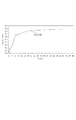
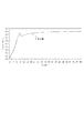
RAM9にあらかじめ設定されている比較用データである光量Aについて説明を行う。括弧内の数値は、一例である。RAM9には、点灯直後の光量Xに応じた電圧V1から電圧V2への切換時間T1、T2、T3があらかじめ設定されている。冷陰極管3の点灯直後の光量は、図5に示すように環境温度が高いほど大きくなる。本実施形態では、環境温度が15度及び30度での点灯開始から2秒後の光量を比較用の基準値として用いており、15度での光量をA(0.18)、30度での光量をB(0.30)としている。なお、単位は電圧で示してある。
The amount of light A, which is comparison data preset in the
次に切換時間T1、T2、T3について説明を行う。図6は、本実施形態にける、閑居温度15度で電圧の切換時間を6秒とした場合の光量変化特性である。この場合、安定光量に到達する時間は、21秒である。図7は、環境温度15度において電圧の切換時間を7秒とした場合の光量変化特性である。この場合、安定光量に到達する時間は、19秒である。図8は、環境温度15度において電圧の切換時間を8秒とした場合の光量変化特性である。この場合、安定光量に到達する時間は、12秒である。図9は、環境温度15度において電圧の切換時間を9秒とした場合の光量変化特性である。この場合、安定光量に到達する時間は、13秒である。図10は、環境温度15度において電圧の切換時間を10秒とした場合の光量変化特性である。この場合、安定光量に到達する時間は、14秒である。 Next, the switching times T1, T2, and T3 will be described. FIG. 6 shows the light quantity change characteristics when the quiet temperature is 15 degrees and the voltage switching time is 6 seconds in this embodiment. In this case, the time to reach a stable light amount is 21 seconds. FIG. 7 shows the light quantity change characteristic when the voltage switching time is 7 seconds at an environmental temperature of 15 degrees. In this case, the time for reaching the stable light amount is 19 seconds. FIG. 8 shows the light quantity change characteristic when the voltage switching time is 8 seconds at the environmental temperature of 15 degrees. In this case, the time to reach the stable light amount is 12 seconds. FIG. 9 shows the light quantity change characteristics when the voltage switching time is 9 seconds at an environmental temperature of 15 degrees. In this case, the time to reach a stable light amount is 13 seconds. FIG. 10 shows the light quantity change characteristics when the voltage switching time is 10 seconds at an environmental temperature of 15 degrees. In this case, the time to reach the stable light amount is 14 seconds.
図6、図7に示されるように、初期電圧V1の印加時間が短い場合は、光量のオーバーシュートが発生しない為、安定光量に到達する時間が長くなる。逆に、図9、図10に示されるように初期電圧V1の印加時間が長すぎても光量のオーバーシュート量が大きくなり、安定光量に到達する時間は、長くなる。よって本実施形態では、安定光量に到達する時間が極力短くなるように、切換時間T2は図10で示される8秒に設定されている。同様に切り換え時間T1、T3もそれぞれ安定光量に到達する時間が極力短くなるようにT1は10秒、T3は6秒に設定されている。環境温度が高いほど点灯直後の光量値Xは、大きく、立ち上がり時間は短くなる。よって切換時間Tは、光量値Xが大きい程、短く設定されている。 As shown in FIGS. 6 and 7, when the application time of the initial voltage V <b> 1 is short, no overshoot of the light amount occurs, so the time to reach the stable light amount becomes long. On the contrary, as shown in FIGS. 9 and 10, even if the application time of the initial voltage V1 is too long, the amount of overshooting of the light amount becomes large, and the time for reaching the stable light amount becomes long. Therefore, in this embodiment, the switching time T2 is set to 8 seconds shown in FIG. 10 so that the time to reach the stable light amount is as short as possible. Similarly, T1 is set to 10 seconds and T3 is set to 6 seconds so that the switching times T1 and T3 are each as short as possible to reach the stable light amount. The higher the environmental temperature, the larger the light quantity value X immediately after lighting, and the shorter the rise time. Therefore, the switching time T is set shorter as the light quantity value X is larger.
図2に戻って冷陰極管の立上げ動作について説明する。CPU回路部2は、光量Xと光量Aとの比較を行った結果、光量A≧光量Xであれば、S6へと移行し、光量A<光量XであればS7へと移行する。S6においては、CPU回路部2は、あらかじめRAM9に設定されている光量Bと比較を行い、光量B>光量XであればS8へと移行し、光量B≦光量XであればS9へと移行する。S7においては、CPU回路部2は、あらかじめRAM9に設定されている光量A<光量Xの場合に対応する切換時間T1を設定し、S10へと移行する。S8において、CPU回路部2は、あらかじめRAM9に設定されている光量A≦光量X<光量Bの場合に対応する切換時間T2を設定し、S11へと移行する。S9においては、CPU回路部2は、あらかじめRAM9に設定されている光量X≧光量Bの場合に対応する切換時間T3を設定し、S11へと移行する。S10においては、CPU回路部2は、タイマー10がT1になるまで待機し、S13へと移行する。S11においては、CPU回路部2は、タイマー10がT2になるまで待機し、S13へと移行する。S12においては、CPU回路部2は、タイマー10がT3になるまで待機し、S13へと移行する。S13においてCPU回路部2は、点灯回路部8に対し電圧切換信号を出力する。点灯回路部8は、冷陰極管3に対する印加電圧を、初期電圧V1からV1よりも低い画像読取時の電圧V2へと切り換える。電圧V2での点灯は第2の点灯工程に相当する。S15においては、CPU回路部2は、電圧V2へ切り換え後光量が安定する時間待機し、タイマー10による時間計測を終了し、S16へと移行する。S16では、CPU回路部2は画像読取動作を開始する。
Returning to FIG. 2, the startup operation of the cold cathode tube will be described. As a result of comparing the light amount X and the light amount A, the
本実施形態では、点灯直後の光量に基づき3段階で比較判定を行っているが、段階をさらに細かく、もしくは、2段階で判定し、それに応じて、初期電圧印加時間を制御してもよい。 In the present embodiment, the comparison determination is performed in three steps based on the light amount immediately after lighting, but the step may be determined in more detail or in two steps, and the initial voltage application time may be controlled accordingly.
2 CPU回路部
3 冷陰極管
6 光電変換素子
8 点灯回路部
9 RAM
10 タイマー
11 ROM
19 標準白色板
2
10 Timer 11 ROM
19 Standard white plate
Claims (6)
前記光源へ電圧を印加して点灯させる点灯回路と、
前記光源の光量を検出する検出手段と、
前記光源を第1の電圧で点灯させ、その後前記第1の電圧よりも低い第2の電圧に切り換えて点灯させる様前記点灯回路を制御する制御手段と、
を有し、前記制御手段は、前記検出手段の出力に基づいて、前記第1の電圧から前記第2の電圧へ切り換えるまでの切換時間を設定することを特徴とする画像読取装置。 A light source for exposing the document;
A lighting circuit for applying a voltage to the light source to light it;
Detecting means for detecting the light quantity of the light source;
Control means for controlling the lighting circuit so that the light source is lit at a first voltage and then switched to a second voltage lower than the first voltage.
And the control means sets a switching time until switching from the first voltage to the second voltage based on the output of the detection means.
前記光源を第1の電圧で点灯させる第1の点灯工程と、
前記光源の光量を検知する検知工程と、
前記検知工程で検知された光量に基づいて、前記第1の電圧よりも低い第2の電圧に切り換えまでの切換時間を設定する設定工程と、
前記設定工程で設定された切換時間に基づいて前記光源を前記第2の電圧で点灯させる第2の点灯工程と、
を有することを特徴とする画像読取装置の制御方法。 In a control method of an image reading apparatus having a light source that exposes a document and a lighting circuit that applies a voltage to the light source to turn it on,
A first lighting step of lighting the light source at a first voltage;
A detection step of detecting the light quantity of the light source;
A setting step for setting a switching time until switching to a second voltage lower than the first voltage, based on the amount of light detected in the detection step;
A second lighting step of lighting the light source at the second voltage based on the switching time set in the setting step;
An image reading apparatus control method comprising:
Priority Applications (1)
| Application Number | Priority Date | Filing Date | Title |
|---|---|---|---|
| JP2007266607A JP2009098175A (en) | 2007-10-12 | 2007-10-12 | Image reading apparatus |
Applications Claiming Priority (1)
| Application Number | Priority Date | Filing Date | Title |
|---|---|---|---|
| JP2007266607A JP2009098175A (en) | 2007-10-12 | 2007-10-12 | Image reading apparatus |
Publications (2)
| Publication Number | Publication Date |
|---|---|
| JP2009098175A true JP2009098175A (en) | 2009-05-07 |
| JP2009098175A5 JP2009098175A5 (en) | 2010-11-25 |
Family
ID=40701285
Family Applications (1)
| Application Number | Title | Priority Date | Filing Date |
|---|---|---|---|
| JP2007266607A Withdrawn JP2009098175A (en) | 2007-10-12 | 2007-10-12 | Image reading apparatus |
Country Status (1)
| Country | Link |
|---|---|
| JP (1) | JP2009098175A (en) |
-
2007
- 2007-10-12 JP JP2007266607A patent/JP2009098175A/en not_active Withdrawn
Similar Documents
| Publication | Publication Date | Title |
|---|---|---|
| US6564028B2 (en) | Method of initializing an image reading device | |
| JP4620025B2 (en) | Image reading apparatus, information processing apparatus, and program | |
| US8314977B2 (en) | Image reading device and image forming apparatus | |
| JP2009098175A (en) | Image reading apparatus | |
| JP5511231B2 (en) | Image reading apparatus and method for controlling the apparatus | |
| US6665097B1 (en) | Image reading apparatus | |
| JP3631100B2 (en) | Image reading apparatus and image reading method | |
| JP2004096157A (en) | Image reading apparatus and document size discriminating method thereof | |
| JP2005045309A (en) | Control method of image scanner | |
| JP2586492B2 (en) | Document illumination device | |
| JP3625419B2 (en) | Image reading device | |
| JP4955532B2 (en) | Image reading apparatus and image forming apparatus | |
| JP2009272860A (en) | Image reading device, and control method of image reading device | |
| JP2005045310A (en) | Control method of image scanner | |
| JP2002281201A (en) | Image reader | |
| JP2008263292A (en) | Image reader | |
| JP2644487B2 (en) | Image reading device | |
| JP2012178652A (en) | Original reader and image forming apparatus | |
| JP2005114998A (en) | Image forming apparatus and method for controlling heat-fixing device | |
| JP2005094135A (en) | Image reader | |
| US20050206976A1 (en) | Method for detecting deterioration of an exposure lamp | |
| JP2008067324A (en) | Image reader and image forming apparatus | |
| JP2005184489A (en) | Image reading device | |
| JP2007267031A (en) | Image forming apparatus | |
| JP2019124825A (en) | Device and dew condensation prevention method |
Legal Events
| Date | Code | Title | Description |
|---|---|---|---|
| RD04 | Notification of resignation of power of attorney |
Free format text: JAPANESE INTERMEDIATE CODE: A7424 Effective date: 20100201 |
|
| RD01 | Notification of change of attorney |
Free format text: JAPANESE INTERMEDIATE CODE: A7421 Effective date: 20100630 |
|
| A521 | Written amendment |
Free format text: JAPANESE INTERMEDIATE CODE: A523 Effective date: 20101008 |
|
| A621 | Written request for application examination |
Free format text: JAPANESE INTERMEDIATE CODE: A621 Effective date: 20101008 |
|
| A761 | Written withdrawal of application |
Free format text: JAPANESE INTERMEDIATE CODE: A761 Effective date: 20120217 |