JP2009093068A - Method of manufacturing scratch-resistant article - Google Patents
Method of manufacturing scratch-resistant article Download PDFInfo
- Publication number
- JP2009093068A JP2009093068A JP2007265641A JP2007265641A JP2009093068A JP 2009093068 A JP2009093068 A JP 2009093068A JP 2007265641 A JP2007265641 A JP 2007265641A JP 2007265641 A JP2007265641 A JP 2007265641A JP 2009093068 A JP2009093068 A JP 2009093068A
- Authority
- JP
- Japan
- Prior art keywords
- layer
- zirconium oxide
- refractive index
- resistant article
- scratch
- Prior art date
- Legal status (The legal status is an assumption and is not a legal conclusion. Google has not performed a legal analysis and makes no representation as to the accuracy of the status listed.)
- Pending
Links
Images


Abstract
Description
本発明は、高屈折率の酸化ジルコニウムからなる層を有する耐擦傷性物品の製造方法に関する。 The present invention relates to a method for producing an abrasion-resistant article having a layer made of zirconium oxide having a high refractive index.
近年、各種レンズ、携帯電話の表示板を始めとする各種ディスプレイのカバー等、光の透過を目的とした物品には、光の反射を抑制し、光の透過性を高めるために、その表面に反射防止層が形成されている。特に、眼鏡やカメラ等のレンズにおいては、高い屈折率を有するレンズほど表面における光の反射率が上昇するため、屈折率の異なる無機薄層を交互に積層させて光の干渉作用を利用した無機反射防止層が広く用いられている。
このような無機反射防止層の形成に用いられる物質は無機酸化物(金属酸化物)である。特に、酸化ケイ素(SiO2)層と酸化ジルコニウム(ZrO2)層の膜厚を調節して、これらの層を交互に積層させ、広い帯域を持たせた無機反射防止層が多く用いられている(例えば、特許文献1参照)。
In recent years, articles intended for light transmission, such as various lenses and covers for various displays such as mobile phone display boards, are used on the surface to suppress light reflection and increase light transmission. An antireflection layer is formed. In particular, in lenses such as eyeglasses and cameras, the higher the refractive index, the higher the reflectance of light on the surface. Therefore, inorganic thin layers having different refractive indices are laminated alternately to make use of the light interference effect. Antireflection layers are widely used.
A substance used for forming such an inorganic antireflection layer is an inorganic oxide (metal oxide). In particular, an inorganic antireflection layer having a wide band is often used by adjusting the film thickness of a silicon oxide (SiO 2 ) layer and a zirconium oxide (ZrO 2 ) layer and alternately laminating these layers. (For example, refer to Patent Document 1).
しかしながら、特許文献1に記載されるZrO2層とSiO2層から形成される反射防止層では、ZrO2層の屈折率が1.99とあまり高くない。ZrO2層の屈折率が低いと、反射防止効果が低いという問題がある。また屈折率が低いということは同時に密度や硬度が低いということを意味し、それは、ZrO2層の耐擦傷性が十分ではなく、結果としてレンズとしての耐擦傷性が十分ではないという問題があった。
そこで本発明は、このような事情に鑑みてなされたものであり、これまで存在しなかった超高屈折率の酸化ジルコニウムからなる表面層を備えた耐擦傷性物品の製造方法を提供することを目的とする。さらに、そのような超高屈折率の酸化ジルコニウム層と低屈折率層とからなる反射防止層を備えた耐擦傷性物品の製造方法を提供することも目的とする。
However, in the antireflection layer formed from the ZrO 2 layer and the SiO 2 layer described in Patent Document 1, the refractive index of the ZrO 2 layer is not so high as 1.99. If the refractive index of the ZrO 2 layer is low, there is a problem that the antireflection effect is low. Also, the low refractive index means that the density and hardness are low at the same time, which means that the scratch resistance of the ZrO 2 layer is not sufficient, and as a result, the scratch resistance as a lens is not sufficient. It was.
Therefore, the present invention has been made in view of such circumstances, and provides a method for producing an abrasion-resistant article having a surface layer made of zirconium oxide having an ultrahigh refractive index that has not existed so far. Objective. It is another object of the present invention to provide a method for producing a scratch-resistant article provided with an antireflection layer composed of such an ultrahigh refractive index zirconium oxide layer and a low refractive index layer.
本発明者は、鋭意研究の結果、所定の条件下におけるイオンアシスト蒸着を利用することにより、超高屈折率の酸化ジルコニウム層を得ることに成功し、その知見をもとに本発明を完成した。
すなわち、本発明は、基板の上に薄層を形成してなる耐擦傷性物品の製造方法であって、前記薄層は単層膜または多層膜からなり、前記単層膜および多層膜は、少なくとも酸化ジルコニウムからなる層(以下、単に「酸化ジルコニウム層」ともいう)を含み、前記酸化ジルコニウム層を、窒素ガス、アルゴンガス、またはこれらの混合ガスを導入しながらイオンアシスト蒸着により前記基板上に形成することを特徴とする。
本発明の耐擦傷性物品の製造方法によれば、所定のガスを導入しながらイオンアシスト蒸着を行うので、屈折率(550nm)が2.0以上の超高屈折率の酸化ジルコニウム層を容易に得ることができる。
As a result of earnest research, the present inventor succeeded in obtaining a zirconium oxide layer having an ultrahigh refractive index by utilizing ion-assisted deposition under predetermined conditions, and completed the present invention based on the knowledge. .
That is, the present invention is a method for producing a scratch-resistant article formed by forming a thin layer on a substrate, wherein the thin layer is a single layer film or a multilayer film, the single layer film and the multilayer film, Including at least a layer made of zirconium oxide (hereinafter, also simply referred to as “zirconium oxide layer”). The zirconium oxide layer is formed on the substrate by ion-assisted deposition while introducing nitrogen gas, argon gas, or a mixed gas thereof. It is characterized by forming.
According to the method for manufacturing a scratch-resistant article of the present invention, since ion-assisted deposition is performed while introducing a predetermined gas, an ultrahigh refractive index zirconium oxide layer having a refractive index (550 nm) of 2.0 or more can be easily formed. Obtainable.
本発明では、前記薄層が、低屈折率層と酸化ジルコニウムからなる高屈折率層とが交互に複数積層されてなる反射防止層であることが好ましい。
この発明によれば、基板の上に形成される薄層が、SiO2等からなる低屈折率層と酸化ジルコニウムからなる高屈折率層とが交互に複数積層されてなる反射防止層であるので、耐擦傷性に優れるだけでなく、反射防止効果にも非常に優れている。
In the present invention, the thin layer is preferably an antireflection layer in which a plurality of low refractive index layers and high refractive index layers made of zirconium oxide are alternately stacked.
According to this invention, the thin layer formed on the substrate is an antireflection layer in which a plurality of low refractive index layers made of SiO 2 or the like and high refractive index layers made of zirconium oxide are alternately stacked. In addition to excellent scratch resistance, the antireflection effect is also very good.
本発明では、前記基板の上にプライマー層を介しあるいは介さずにハードコート層を形成し、前記ハードコート層の上に前記反射防止層を形成することが好ましい。
この発明によれば、基板上にハードコート層を形成し、その上に前記した反射防止層を形成するので、反射防止効果に優れるだけでなく、より傷の付きにくい耐擦傷性物品を製造することができる。
In the present invention, it is preferable that a hard coat layer is formed on the substrate with or without a primer layer, and the antireflection layer is formed on the hard coat layer.
According to this invention, the hard coat layer is formed on the substrate, and the antireflection layer described above is formed thereon, so that not only the antireflection effect is excellent, but also a scratch-resistant article that is hard to be scratched is manufactured. be able to.
本発明では、前記酸化ジルコニウム層の波長550nmにおける屈折率が2.0以上であることが好ましい。
この発明によれば、酸化ジルコニウム層の屈折率が2.0以上であって、これまでに知られている酸化ジルコニウム層よりも屈折率が高い。従って、密度や硬度も高く、この酸化ジルコニウムを適当な物品の表面に薄層として形成すことで、極めて耐擦傷性に優れた物品を製造することができる。さらに、この酸化ジルコニウム層を高屈折率層とし、SiO2等の適当な低屈折率層と交互に積層することで、積層数が少なくとも非常に反射防止効果に優れた反射防止層を提供することができる。それ故、反射防止効果にも極めて優れた耐擦傷性物品を容易に製造することが可能となる。
なお、本発明においては、酸化ジルコニウム層の屈折率は、2.01以上であることが好ましく、2.02以上であることがより好ましい。ただし、屈折率が高くなりすぎると、酸化ジルコニウム層が密になり過ぎることで内部応力が高くなり、酸化ジルコニウム自体がもろくなるおそれがあるため、酸化ジルコニウム層の屈折率は、2.1以下であることが好ましく、2.08以下であることがより好ましい。
In the present invention, the refractive index of the zirconium oxide layer at a wavelength of 550 nm is preferably 2.0 or more.
According to the present invention, the refractive index of the zirconium oxide layer is 2.0 or more, and the refractive index is higher than that of the conventionally known zirconium oxide layers. Therefore, an article having extremely high scratch resistance can be produced by forming the zirconium oxide as a thin layer on the surface of an appropriate article, having a high density and hardness. Furthermore, the zirconium oxide layer and the high refractive index layer, by alternately laminating a suitable low refractive index layer of SiO 2 or the like, the number of layers to provide an excellent antireflection layer on at least very antireflection effect Can do. Therefore, it is possible to easily produce a scratch-resistant article that is extremely excellent in the antireflection effect.
In the present invention, the refractive index of the zirconium oxide layer is preferably 2.01 or more, and more preferably 2.02 or more. However, if the refractive index becomes too high, the zirconium oxide layer becomes too dense and the internal stress becomes high and the zirconium oxide itself may become brittle. Therefore, the refractive index of the zirconium oxide layer is 2.1 or less. It is preferable that it is 2.08 or less.
以下に、本発明の実施形態を詳細に説明する。本実施形態に係る耐擦傷性物品は、表面に無機反射防止層を備えたプラスチック眼鏡レンズ(以下、「眼鏡レンズ」あるいは単に「レンズ」ともいう。)である。 Hereinafter, embodiments of the present invention will be described in detail. The scratch-resistant article according to the present embodiment is a plastic spectacle lens (hereinafter also referred to as “glass lens” or simply “lens”) having an inorganic antireflection layer on the surface.
〔眼鏡レンズの構成〕
図1は、眼鏡レンズ100の構成を模式的に示す断面図である。眼鏡レンズ100は、レンズ基板40の上に多層層からなる無機反射防止層43が形成され、さらにその上に防汚層44が形成されている。なお、レンズ基板40は、プラスチック基板41とハードコート層42とから形成されている。
[Configuration of eyeglass lens]
FIG. 1 is a cross-sectional view schematically showing the configuration of the
無機反射防止層43は、低屈折率材料層(L)がSiO2(n=1.45)、高屈折率材料層(H)がZrO2(n≧2.0)から構成される。この無機反射防止層43は、図1に示すように、ハードコート層42に接する側から、低屈折率材料のSiO2層431がまず積層され、その上面に高屈折率材料のZrO2層432が積層され、以下、SiO2層433、ZrO2層434、SiO2層435のように交互に積層されて、最終的に計5層からなる無機反射防止層43を構成している。
In the
〔眼鏡レンズ100の製造方法〕
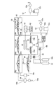
図2は、眼鏡レンズ100を製造するための蒸着装置50を模式的に示した図である。以下、蒸着装置50の構成と、基板40上への無機反射防止層43および防汚層44の形成による眼鏡レンズ100の製造方法について詳述する。
[Method of Manufacturing Eyeglass Lens 100]
FIG. 2 is a diagram schematically showing a
(蒸着装置50の構成)
図3(a)および(b)に、レンズ基板40を搭載する支持装置80の概要を示す。この支持装置80は、上方に凸に湾曲した円盤状のドーム81を備えており、ドーム81に同心円状に複数のレンズ基板40を配列し、その配列を保持した状態で回転できるようになっている。図3(a)に示した支持装置80においては、眼鏡レンズとなる複数のレンズ基板40を、回転軸82を中心に同心円状に1〜4段にセットできるようになっている。
(Structure of the vapor deposition apparatus 50)
3A and 3B show an outline of a
図2に示す蒸着装置50により、レンズ基板40上に、イオンアシスト蒸着により無機反射防止層43を形成する。蒸着装置50は、支持装置80が内部を通過可能な3つのチャンバーCH1、CH2およびCH3を備えている。これらのチャンバーCH1〜CH3は連結され、支持装置80がレンズ基板40を保持した状態で通過可能である。また、各々のチャンバーCH1〜CH3は相互に密封できるようになっており、各チャンバーCH1〜CH3の内圧を真空生成装置52、53および54によりそれぞれ制御できるようになっている。
The
チャンバーCH1は、エントランスまたはゲートチャンバーであり、外部から支持装置80を導入した後、一定時間、一定の圧力以下にチャンバーCH1の内部を保持することにより、脱ガスを行う。チャンバーCH1には、ロータリポンプ52a、ルーツポンプ52bおよびクライオポンプ52cを備えた真空生成装置52が設けられている。
The chamber CH1 is an entrance or gate chamber, and after introducing the
チャンバーCH2は、無機反射防止層(AR層)43を形成する第2のチャンバーである。このため、このチャンバーCH2の内部には、AR層蒸着源55aおよび55b、このAR層蒸着源55a,55bを蒸着させる電子銃56、および蒸着量を調整する開閉可能なシャッター57が設けられている。また、AR層43は、酸化ケイ素(SiO2)を主成分とする薄層と、ZrO2(必要に応じて、他にTiO2、Nb2O3、Ta2O5など)を主成分とする薄層とが交互に積層されてなる構成である。このため、少なくとも2つの蒸着源55aおよび55bが用意されている。チャンバーCH2は、ロータリポンプ53a、ルーツポンプ53bおよびクライオポンプ53cを備えた真空生成装置53により適当な圧力に保持される。
The chamber CH2 is a second chamber in which the inorganic antireflection layer (AR layer) 43 is formed. For this reason, inside the chamber CH2, AR
チャンバーCH3は、フッ素含有有機ケイ素化合物を蒸着することにより防汚性の最表面層を形成する第3のチャンバーである。そのため、チャンバー内部には、フッ素含有有機ケイ素化合物が含浸された蒸着源と、加熱ヒータ(ハロゲンランプ)と、補正板とが設置されている(図示せず)。補正板は、固定式であり開度を調整することにより、支持装置80に向かって放出される蒸着量を調整できるようになっている。チャンバーCH3は、ロータリポンプ54a、ルーツポンプ54bおよびターボ分子ポンプ54cを備えた真空生成装置54により適当な圧力に保持される。
The chamber CH3 is a third chamber for forming an antifouling outermost layer by depositing a fluorine-containing organosilicon compound. Therefore, an evaporation source impregnated with a fluorine-containing organosilicon compound, a heater (halogen lamp), and a correction plate are installed inside the chamber (not shown). The correction plate is a fixed type, and the amount of vapor deposition emitted toward the
(無機反射防止層43の形成)
以下に、蒸着装置50を用いた場合の好ましい蒸着条件について説明する。
まず、第1層は、基板40上に酸化ケイ素を蒸着して成層する。第2層では、酸化ジルコニウムを蒸着させると同時にイオンを照射することによって、高屈折率の酸化ジルコニウムを成層する。この際の導入ガスは窒素ガス、アルゴンガスを各々の単独か、またはそれぞれを任意の比率で含んだ混合ガスを用いる。また、このときの加速電圧は200〜1000V、加速電流は50〜300mA、バイアス電流は加速電流値の1.5〜3.0倍,ガス流量は15〜25sccmの範囲で調整する。ただし、加速電圧としては600〜1000V、加速電流は150〜300mA、バイアス電流は加速電流の1.5倍、ガス流量は20sccm程度が酸化ジルコニウム層の屈折率向上の観点より好ましい。以上の条件の中でも加速電圧800〜1000V、加速電流240〜260mAが特に好ましい。
(Formation of inorganic antireflection layer 43)
Below, the preferable vapor deposition conditions at the time of using the
First, the first layer is formed by depositing silicon oxide on the
第3層として酸化ケイ素層を形成後、第4層において、酸化ジルコニウムを蒸着させると同時にイオンを照射する。なお、この際のイオンの照射条件(加速電圧、加速電流、バイアス電流、導入ガス種類、導入ガス流量)は第2層と同じである必要は無い。第4層を形成後、第5層の酸化ケイ素層を形成する。その後、最表面に後述する防汚層44を形成する。
ここで、イオンアシスト蒸着を行うのは、第2層あるいは第4層のみでもよい。すなわち、第2、第4層のいずれか任意の層をイオンアシスト蒸着により形成してもよい。もちろんすべての酸化ジルコニウム層をイオンアシスト蒸着により形成することが最も効果的である。
After the silicon oxide layer is formed as the third layer, zirconium oxide is vapor-deposited in the fourth layer and simultaneously irradiated with ions. The ion irradiation conditions (acceleration voltage, acceleration current, bias current, introduced gas type, introduced gas flow rate) at this time are not necessarily the same as those in the second layer. After forming the fourth layer, a fifth silicon oxide layer is formed. Thereafter, an
Here, ion-assisted deposition may be performed only on the second layer or the fourth layer. That is, any one of the second and fourth layers may be formed by ion-assisted deposition. Of course, it is most effective to form all the zirconium oxide layers by ion-assisted deposition.
(防汚層44の形成)
チャンバーCH3に支持装置80を移動した後、以下のようにして防汚層44を形成する。まず、適当なフッ素含有有機ケイ素化合物(例えば、信越化学工業株式会社製 KY−130)を、フッ素系溶剤(例えば、住友スリーエム株式会社製:ノベックHFE−7200)に希釈して固形分濃度2〜4質量%の溶液を調製し、これを多孔質セラミックス製のペレットに0.5〜2g程度含浸させ乾燥させたものを蒸着源とする。
この蒸着源をチャンバーCH3にセットする。次に、ハロゲンランプを加熱ヒータとして使用し、蒸着源のペレットを500〜700℃に加熱して、フッ素含有有機ケイ素化合物を蒸発させる。蒸着時間は2〜4分として、レンズ基板40(反射防止層43)の表面に防汚層44を形成する。
反射防止層43および/または防汚層44をレンズ基板40の両面に形成したい場合は、反射防止層43および/または防汚層44の形成後、支持装置80をチャンバーから取り出し、レンズを反転して凸面を下にして支持装置80のドーム81にセットし、再び上記と同様の処理を行うことによって、レンズ基板40の両面に反射防止層43および/または防汚層44を形成する。
(Formation of antifouling layer 44)
After moving the
This vapor deposition source is set in the chamber CH3. Next, using a halogen lamp as a heater, the vapor deposition source pellet is heated to 500 to 700 ° C. to evaporate the fluorine-containing organosilicon compound. The deposition time is 2 to 4 minutes, and the
When it is desired to form the
前記した実施形態によれば、以下の効果がある。
(1)反射防止層43を構成する酸化ジルコニウム層432、434の屈折率が2.0以上と極めて高いので、密度および硬度も高く、耐擦傷性に極めて優れる眼鏡レンズ100を製造することができる。
(2)眼鏡レンズ100の反射防止層43は、屈折率が2.0以上の酸化ジルコニウム層432、434と、低屈折率層(酸化ケイ素層)431、433、435とが交互に積層されているので積層数が5層であっても優れた反射防止効果を発揮できる。
(3)酸化ジルコニウム層432、434を成層する方法が、公知のイオンアシスト蒸着であり、使用するガスも窒素ガスあるいはアルゴンガスであるので、簡便な方法により、これまで存在しなかった超高屈折率の酸化ジルコニウム層を製造することができる。
According to the above-described embodiment, there are the following effects.
(1) Since the refractive indexes of the zirconium oxide layers 432 and 434 constituting the
(2) The
(3) The method of forming the zirconium oxide layers 432 and 434 is known ion-assisted deposition, and the gas used is nitrogen gas or argon gas. Rate zirconium oxide layers can be produced.
なお、本発明は前述の実施形態に限定されるものではなく、本発明の目的を達成できる範囲での変形、改良等は本発明に含まれるものである。
例えば、本実施形態では、耐擦傷性物品として眼鏡レンズを選び、その反射防止層に適用した例を説明したが、他に、カメラレンズ、望遠鏡用レンズ、顕微鏡用レンズ、ステッパー用集光レンズなど各種の薄型光学レンズに幅広く適用することができる。
It should be noted that the present invention is not limited to the above-described embodiments, and modifications, improvements, and the like within the scope that can achieve the object of the present invention are included in the present invention.
For example, in this embodiment, an example in which a spectacle lens is selected as the scratch-resistant article and applied to the antireflection layer has been described. In addition, a camera lens, a telescope lens, a microscope lens, a stepper condenser lens, and the like It can be widely applied to various thin optical lenses.
次に、本発明を実施例によりさらに詳細に説明するが、本発明はこれらの例によってなんら限定されるものではない。なお、各実施例とも、実施形態と同様の構造・機能を有する装置等は同じ符号を付けて説明する。
〔実施例1〕
本実施例では、前記した実施形態において、具体的条件を設定して眼鏡レンズ100を製造した。眼鏡レンズ100のプラスチック基板40としては、セイコーエプソン株式会社製のセイコースーパーソブリンにハードコート層42を形成したものを用いた。以下に、前記基板40上への無機反射防止層43と防汚層44の形成について具体的条件を記載する。
EXAMPLES Next, although an Example demonstrates this invention further in detail, this invention is not limited at all by these examples. In each example, devices having the same structure and function as those in the embodiment will be described with the same reference numerals.
[Example 1]
In this example, the
(無機反射防止層43の形成)
以下に、無機反射防止層43の具体的な形成方法について説明する。
まず、レンズ基板40の凹面を下にして、支持装置80のドーム81にセットした。次に、温度を60℃に設定したチャンバーCH1で脱ガスした後、チャンバーCH2において、加速電圧500V、加速電流250mA、バイアス電流380mA、酸素ガス導入流量20sccmの条件でイオンクリーニングを2分間行った。これは、レンズ基板40と反射防止層との密着性を向上させるために、レンズ基板40表面を清浄化することを目的としたものである。
(Formation of inorganic antireflection layer 43)
Hereinafter, a specific method for forming the
First, the
引き続き、無機反射防止層43を形成した。その詳細な成層手順は以下の通りである。まず、第1層として酸化ケイ素(SiO2)層431を真空蒸着により形成した。その後、真空度が6.0×10⁻³Pa付近になるように設定し、第2層として加速電圧800V、加速電流250mA、バイアス電流は加速電流の1.5倍(375mA)、窒素ガス20sccmを導入しながらイオンアシスト蒸着を行い、酸化ジルコニウム層432を形成した。そして、第3層として第1層と同様の酸化ケイ素層433を真空蒸着により形成した。次に、第4層として、第2層と同じ条件でイオンアシスト蒸着を行って酸化ジルコニウム層434を形成し、最後に、第5層として酸化ケイ素層435を蒸着により形成した。結果として計5層からなる無機反射防止層43をレンズ基板40の上に形成した。
Subsequently, an
蒸着後チャンバー内に酸素100%ガスを導入し、圧力を4.0×10⁻²Paに制御しつつ、高周波プラズマ発生装置でプラズマを発生させた。プラズマ発生条件は、13.56MHz、400Wで、2分間処理を行った。これは、無機反射防止層43表面を活性化させ、次工程における防汚層44との化学結合を促進させることを目的としたものである。
After vapor deposition, 100% oxygen gas was introduced into the chamber, and plasma was generated by a high-frequency plasma generator while controlling the pressure at 4.0 × 10 −2 Pa. Plasma generation conditions were 13.56 MHz and 400 W, and the treatment was performed for 2 minutes. The purpose of this is to activate the surface of the
(防汚層44の形成)
チャンバーCH3に支持装置80を移動した後、以下のようにして防汚層44を形成した。
まず、下記式(1)で示されるフッ素含有有機ケイ素化合物(信越化学工業株式会社製 KY−130)を、フッ素系溶剤(住友スリーエム株式会社製:ノベックHFE−7200)に希釈して固形分濃度3質量%溶液を調製し、これを多孔質セラミックス製のペレットに1g含浸させ乾燥させたものを蒸着源59とした。
(Formation of antifouling layer 44)
After moving the
First, a fluorine-containing organosilicon compound represented by the following formula (1) (KY-130 manufactured by Shin-Etsu Chemical Co., Ltd.) is diluted with a fluorine-based solvent (Sumitomo 3M Co., Ltd .: Novec HFE-7200) to obtain a solid content concentration. A vapor deposition source 59 was prepared by preparing a 3% by mass solution, impregnating 1 g of the porous ceramic pellets and drying it.

この蒸着源59をチャンバーCH3にセットした。次に、ハロゲンランプを加熱ヒータ68として使用し、蒸着源59のペレットを600℃に加熱して、フッ素含有有機ケイ素化合物を蒸発させた。蒸着時間を3分として、レンズ基板40(反射防止層43)の表面に防汚層44を形成した。
防汚層44の形成後、支持装置80をチャンバーから取り出し、レンズを反転して凸面を下にして支持装置80のドーム81にセットし、再び上記と同様の処理を行うことによって、レンズ基板40の両面に防汚層44を形成した。
防汚層44の形成後、支持装置80をチャンバーから取り出し、レンズを反転して凸面を下にして支持装置80のドーム81にセットし、再び上記と同様の処理を行うことによって、レンズ基板40の両面に反射防止層43および防汚層44を形成した。
This deposition source 59 was set in the chamber CH3. Next, using a halogen lamp as the heater 68, the pellet of the vapor deposition source 59 was heated to 600 ° C. to evaporate the fluorine-containing organosilicon compound. The
After the
After the
〔実施例2〕
酸化ジルコニウム層形成時に、アルゴンガスを20sccm導入してイオンアシスト蒸着を行った。その他の操作・条件は実施例1と同様である。
[Example 2]
During the formation of the zirconium oxide layer, 20 sccm of argon gas was introduced to perform ion-assisted deposition. Other operations and conditions are the same as those in the first embodiment.
〔実施例3〕
酸化ジルコニウム層形成時に、窒素ガスを15sccm、アルゴンガスを5sccm導入してイオンアシスト蒸着を行った。その他の操作・条件は実施例1と同様である。
Example 3
When forming the zirconium oxide layer, ion-assisted deposition was performed by introducing 15 sccm of nitrogen gas and 5 sccm of argon gas. Other operations and conditions are the same as those in the first embodiment.
〔比較例1〕
実施例1において、真空度が2.0×10⁻³Pa付近になるように設定し、酸化ジルコニウム層をイオンアシストさせずに形成した。すなわち、イオンアシストを一切行わずに、単なる蒸着により反射防止層を形成した。その他の操作・条件は実施例1と同様である。
[Comparative Example 1]
In Example 1, the degree of vacuum was set to be around 2.0 × 10 −3 Pa, and the zirconium oxide layer was formed without ion assist. That is, the antireflection layer was formed by simple vapor deposition without performing any ion assist. Other operations and conditions are the same as those in the first embodiment.
〔比較例2〕
酸化ジルコニウム層形成時に、酸素ガスを20sccm導入してイオンアシスト蒸着を行った。その他の操作・条件は実施例1と同様である。
[Comparative Example 2]
During the formation of the zirconium oxide layer, 20 sccm of oxygen gas was introduced to perform ion-assisted deposition. Other operations and conditions are the same as those in the first embodiment.
〔比較例3〕
比較例1において、蒸着中の真空度が4.0×10⁻⁴Pa付近になるように設定した。
その他の操作・条件は実施例1と同様である。
[Comparative Example 3]
In Comparative Example 1, the degree of vacuum during vapor deposition was set to be around 4.0 × 10 −4 Pa.
Other operations and conditions are the same as those in the first embodiment.
〔評価方法〕
以上の実施例1〜3、および比較例1〜3で得られたプラスチック眼鏡レンズ(以下、単に「レンズ」ともいう)の物性を、以下に示す評価方法で評価した。評価項目は、屈折率および耐擦傷性である。その結果を表1に示す。
〔Evaluation methods〕
The physical properties of the plastic spectacle lenses (hereinafter also simply referred to as “lenses”) obtained in Examples 1 to 3 and Comparative Examples 1 to 3 were evaluated by the evaluation methods shown below. Evaluation items are refractive index and scratch resistance. The results are shown in Table 1.
(1)屈折率
BK7ガラス基板上に、前述した各条件で100nm厚の酸化ジルコニウム層を形成し、分光エリプソメータ(SOPRA社製)により屈折率を測定した。測定波長は550nmである。
(2)耐擦傷性(ベイヤー試験)
COLTS Laboratories社製ベイヤー試験機を用い、上述した条件で製造された試験品(眼鏡レンズ)と標準レンズ(株式会社サンルックス製:CR39)を質量500gのメディアで600回往復させて同時に傷をつけた(COLTS Laboratories社の指定する標準条件)。その傷のついたレンズのヘーズ値(スガ試験機株式会社製自動ヘーズコンピュータ)を測定して、下記の式により、基準レンズとのヘーズ値変化の差によりベイヤー値(Bayer Ratio)Rを算出し、耐擦傷性の評価を行った。
R=|HST1−HST0|/|HSA1−HSA0|
ここで、Hはヘーズ値であり、STは、上述の標準レンズ、SAは試験品の眼鏡レンズを意味する。また、ST0、SA0は試験前を意味し、ST1、SA1は試験後を意味する。R値が大きいほど耐擦傷性が良好である。なお、メディアは、ZrO2:21〜23質量%、Al2O3:73〜77質量%、HfO2:0.3〜1.3質量%の組成を有する硬質の砂状粒子である。
試験品と標準レンズ各々3枚について測定を行ってRを算出し、平均値を測定値とした。
(1) Refractive index A zirconium oxide layer having a thickness of 100 nm was formed on the BK7 glass substrate under the above-described conditions, and the refractive index was measured with a spectroscopic ellipsometer (manufactured by SOPRA). The measurement wavelength is 550 nm.
(2) Scratch resistance (Bayer test)
Using a Bayer tester manufactured by COLTS Laboratories, the test product (glasses lens) manufactured under the above-mentioned conditions and a standard lens (manufactured by Sunlux Co., Ltd .: CR39) were reciprocated 600 times with a medium of 500 g in mass, and simultaneously damaged. (Standard conditions specified by COLTS Laboratories). The haze value (automatic haze computer manufactured by Suga Test Instruments Co., Ltd.) of the damaged lens is measured, and the Bayer Ratio R is calculated from the difference in haze value change from the reference lens by the following formula. The scratch resistance was evaluated.
R = | H ST1 −H ST0 | / | H SA1 −H SA0 |
Here, H is a haze value, ST is the above-mentioned standard lens, and SA is a test spectacle lens. ST0 and SA0 mean before the test, and ST1 and SA1 mean after the test. The greater the R value, the better the scratch resistance. Incidentally, the media, ZrO 2: 21 to 23 wt%, Al 2 O 3: 73~77 wt%, HfO 2: is a sand-like particles of hard having a composition of 0.3-1.3 wt%.
R was calculated by measuring three test samples and three standard lenses, and the average value was taken as the measurement value.
〔評価結果〕
表1の結果から、本発明の製造方法で得られた眼鏡レンズでは、酸化ジルコニウム層の屈折率は2.0以上と極めて高く、耐擦傷性に非常に優れていることがわかる。一方、比較例1では、酸化ジルコニウム層を成層する際にイオンアシストを行っておらず、単なる蒸着であるため、酸化ジルコニウム層の屈折率が向上していない。また、比較例2では、酸素ガスを導入しながらイオンアシスト蒸着を行ったが、ZrO2と酸素原子が反応してしまうためか、屈折率はあまり上がらなかった。比較例3は、比較例1において、真空度を上げた場合であるが、酸化ジルコニウム層の屈折率向上と、眼鏡レンズの耐擦傷性向上の程度はわずかであった。
〔Evaluation results〕
From the results in Table 1, it can be seen that in the spectacle lens obtained by the production method of the present invention, the refractive index of the zirconium oxide layer is as extremely high as 2.0 or more, and the scratch resistance is very excellent. On the other hand, in Comparative Example 1, ion assist was not performed when the zirconium oxide layer was formed, and since the deposition was merely vapor deposition, the refractive index of the zirconium oxide layer was not improved. In Comparative Example 2, ion-assisted deposition was performed while introducing oxygen gas, but the refractive index did not increase so much because ZrO 2 and oxygen atoms reacted. In Comparative Example 3, the degree of vacuum was increased in Comparative Example 1, but the degree of improvement in the refractive index of the zirconium oxide layer and the improvement in scratch resistance of the spectacle lens were slight.
本発明の製造方法は、眼鏡レンズ等の分野で好適に利用することができる。 The production method of the present invention can be suitably used in the field of spectacle lenses and the like.
40…レンズ基板、41…プラスチック基板、42…ハードコート層、43…(無機)反射防止層、44…防汚層、50…蒸着装置、52,53,54…真空生成装置、52a,53a,54a…ロータリポンプ、52b,53b,54b…ルーツポンプ、52c,53c…クライオポンプ、54c…ターボ分子ポンプ、55a,55b…AR層蒸着源、56…電子銃、57…シャッター、80…支持装置、81…ドーム、82…回転軸、100…眼鏡レンズ、431,433,435…酸化ケイ素層、432,434…酸化ジルコニウム層
DESCRIPTION OF
Claims (5)
前記薄層は単層膜または多層膜からなり、
前記単層膜および多層膜は、少なくとも酸化ジルコニウムからなる層を含み、
前記酸化ジルコニウムからなる層を、窒素ガス、アルゴンガス、またはこれらの混合ガスを導入しながらイオンアシスト蒸着により前記基板上に形成することを特徴とする耐擦傷性物品の製造方法。 A method for producing a scratch-resistant article formed by forming a thin layer on a substrate,
The thin layer consists of a single layer film or a multilayer film,
The single layer film and the multilayer film include at least a layer made of zirconium oxide,
A method for producing a scratch-resistant article, wherein the layer made of zirconium oxide is formed on the substrate by ion-assisted vapor deposition while introducing nitrogen gas, argon gas, or a mixed gas thereof.
前記薄層が、低屈折率層と酸化ジルコニウムからなる高屈折率層とが交互に複数積層されてなる反射防止層であることを特徴とする耐擦傷性物品の製造方法。 In the manufacturing method of the abrasion-resistant article of Claim 1,
The method for producing a scratch-resistant article, wherein the thin layer is an antireflection layer in which a plurality of low refractive index layers and high refractive index layers made of zirconium oxide are alternately laminated.
前記基板の上にプライマー層を介しあるいは介さずにハードコート層を形成し、
前記ハードコート層の上に前記反射防止層を形成することを特徴とする耐擦傷性物品の製造方法。 In the manufacturing method of the abrasion-resistant article of Claim 2,
A hard coat layer is formed on the substrate with or without a primer layer,
A method for producing a scratch-resistant article, wherein the antireflection layer is formed on the hard coat layer.
前記酸化ジルコニウムからなる層の波長550nmにおける屈折率が2.0以上であることを特徴とする耐擦傷性物品の製造方法。 In the manufacturing method of the abrasion-resistant article in any one of Claims 1-3,
A method for producing a scratch-resistant article, wherein the layer made of zirconium oxide has a refractive index of 2.0 or more at a wavelength of 550 nm.
前記酸化ジルコニウムからなる層の前記屈折率が2.01以上、2.1以下であることを特徴とする耐擦傷性物品の製造方法。 In the manufacturing method of the abrasion-resistant article of Claim 4,
The method for producing a scratch-resistant article, wherein the refractive index of the layer made of zirconium oxide is 2.01 or more and 2.1 or less.
Priority Applications (1)
| Application Number | Priority Date | Filing Date | Title |
|---|---|---|---|
| JP2007265641A JP2009093068A (en) | 2007-10-11 | 2007-10-11 | Method of manufacturing scratch-resistant article |
Applications Claiming Priority (1)
| Application Number | Priority Date | Filing Date | Title |
|---|---|---|---|
| JP2007265641A JP2009093068A (en) | 2007-10-11 | 2007-10-11 | Method of manufacturing scratch-resistant article |
Publications (1)
| Publication Number | Publication Date |
|---|---|
| JP2009093068A true JP2009093068A (en) | 2009-04-30 |
Family
ID=40665093
Family Applications (1)
| Application Number | Title | Priority Date | Filing Date |
|---|---|---|---|
| JP2007265641A Pending JP2009093068A (en) | 2007-10-11 | 2007-10-11 | Method of manufacturing scratch-resistant article |
Country Status (1)
| Country | Link |
|---|---|
| JP (1) | JP2009093068A (en) |
Cited By (2)
| Publication number | Priority date | Publication date | Assignee | Title |
|---|---|---|---|---|
| EP2437084A1 (en) * | 2010-10-01 | 2012-04-04 | Carl Zeiss Vision GmbH | Optical lens with anti-scratch, anti-reflective layer |
| JP2017015983A (en) * | 2015-07-02 | 2017-01-19 | 東海光学株式会社 | Optical product, and plastic lens and spectacles |
-
2007
- 2007-10-11 JP JP2007265641A patent/JP2009093068A/en active Pending
Cited By (5)
| Publication number | Priority date | Publication date | Assignee | Title |
|---|---|---|---|---|
| EP2437084A1 (en) * | 2010-10-01 | 2012-04-04 | Carl Zeiss Vision GmbH | Optical lens with anti-scratch, anti-reflective layer |
| JP2012088700A (en) * | 2010-10-01 | 2012-05-10 | Carl Zeiss Vision Gmbh | Optical lens with scratch-resistant antireflection layer |
| US8982466B2 (en) | 2010-10-01 | 2015-03-17 | Carl Zeiss Vision International Gmbh | Optical lens with scratch-resistant anti-reflective layer |
| US9817155B2 (en) | 2010-10-01 | 2017-11-14 | Carl Zeiss Vision International Gmbh | Optical lens with scratch-resistant anti-reflective layer |
| JP2017015983A (en) * | 2015-07-02 | 2017-01-19 | 東海光学株式会社 | Optical product, and plastic lens and spectacles |
Similar Documents
| Publication | Publication Date | Title |
|---|---|---|
| JP5135753B2 (en) | Optical article | |
| JP4462273B2 (en) | Optical article and manufacturing method thereof | |
| US8789944B2 (en) | Optical article and optical article production method | |
| JP5647924B2 (en) | Manufacturing method of optical member | |
| JP5622468B2 (en) | Lens manufacturing method and lens | |
| JP5265547B2 (en) | Method for producing a smooth and dense optical film | |
| JP4581608B2 (en) | Thin film manufacturing method, optical component manufacturing method, and film forming apparatus | |
| JP2011013654A (en) | Multilayer antireflection layer and method of producing the same, and plastic lens | |
| CN109182972A (en) | Multispectral hard anti-reflection film of large-size sapphire substrate and preparation method thereof | |
| JP2010102157A (en) | Optical article and method for manufacturing the same | |
| JP2005301208A (en) | Method for manufacturing stain proof optical article | |
| JP5698902B2 (en) | Optical article and manufacturing method thereof | |
| JP2021523412A (en) | Curved film and its manufacturing method | |
| JP6381687B2 (en) | Method for forming durable MgO-MgF2 composite film for infrared light antireflection coating | |
| KR20050062535A (en) | Method for obtaining a thin stabilized, fluorine-doped silica layer, thin layer obtained and application thereof in ophthalmic optics | |
| JP2010237637A (en) | Optical article and method of manufacturing the same | |
| JP2009093068A (en) | Method of manufacturing scratch-resistant article | |
| JP2005133131A (en) | Method for forming refractive-index-changing layer | |
| CN114335392B (en) | Preparation process of anti-reflection film for OLED flexible display | |
| JP4249937B2 (en) | Optical member having water-repellent thin film and method for producing lens | |
| JP2009093067A (en) | Zirconium oxide layer, scratch-resistant article and optical article | |
| JP2007156321A (en) | Method for manufacturing optical multilayer filter | |
| JP5779317B2 (en) | Method for manufacturing optical article | |
| JP2010072636A (en) | Optical article and method for manufacturing the same | |
| Jakobs et al. | Characterization of metal-oxide thin films deposited by plasma-assisted reactive magnetron sputtering |