JP2009093039A - Fixing device, image forming apparatus using the same, and an image forming method - Google Patents
Fixing device, image forming apparatus using the same, and an image forming method Download PDFInfo
- Publication number
- JP2009093039A JP2009093039A JP2007265148A JP2007265148A JP2009093039A JP 2009093039 A JP2009093039 A JP 2009093039A JP 2007265148 A JP2007265148 A JP 2007265148A JP 2007265148 A JP2007265148 A JP 2007265148A JP 2009093039 A JP2009093039 A JP 2009093039A
- Authority
- JP
- Japan
- Prior art keywords
- carrier
- recording medium
- roller
- roller pair
- image
- Prior art date
- Legal status (The legal status is an assumption and is not a legal conclusion. Google has not performed a legal analysis and makes no representation as to the accuracy of the status listed.)
- Pending
Links
Images


Landscapes
- Fixing For Electrophotography (AREA)
- Control Or Security For Electrophotography (AREA)
Abstract
Description
本発明は、像担持体上に形成した潜像をトナー及びキャリアからなる液体現像剤によって現像し、このトナー及びキャリアからなるトナー像をさらに記録媒体に転写して、転写されたトナー像を融着し定着する定着装置、画像形成装置及び画像形成方法に関する。 In the present invention, a latent image formed on an image carrier is developed with a liquid developer composed of toner and carrier, the toner image composed of toner and carrier is further transferred to a recording medium, and the transferred toner image is fused. The present invention relates to a fixing device, an image forming apparatus, and an image forming method for fixing and fixing.
液体溶媒中に固体成分からなるトナーを分散させた高粘度の液体現像剤を用いて潜像を現像し、静電潜像を可視化する湿式画像形成装置が種々提案されている。この湿式画像形成装置に用いられる現像剤は、シリコンオイルや鉱物油、食用油等からなる電気絶縁性を有し高粘度の有機溶剤(キャリア液)中に固形分(トナー粒子)を懸濁させたものであり、このトナー粒子は、粒子径が1μm前後と極めて微細である。このような微細なトナー粒子を使用することにより、湿式画像形成装置では、粒子径が7μm程度の粉体トナー粒子を使用する乾式画像形成装置に比べて高画質化が可能である。 Various wet image forming apparatuses that develop a latent image using a high-viscosity liquid developer in which a toner composed of a solid component is dispersed in a liquid solvent and visualize the electrostatic latent image have been proposed. The developer used in this wet image forming apparatus suspends solids (toner particles) in a highly viscous organic solvent (carrier liquid) having electrical insulation properties such as silicon oil, mineral oil, and edible oil. The toner particles are extremely fine with a particle diameter of around 1 μm. By using such fine toner particles, the wet image forming apparatus can achieve higher image quality than a dry image forming apparatus using powder toner particles having a particle diameter of about 7 μm.
上記のような液体現像剤を用いたものとしては、例えば、特許文献1(特開2003−99864号公報)に、一部もしくは全てが不揮発性である溶媒中にトナーを分散させてなる液体現像剤を用いて形成された記録媒体上の未定着画像を加熱定着する画像定着装置であって、上記記録媒体上の未定着画像に対して非接触で該未定着画像の加熱を行う非接触加熱手段と、該非接触加熱手段の加熱により析出せしめられた被析出溶媒を該画像表面から除去する溶媒除去手段とを設けたことを特徴とする画像定着装置が開示されている。
ところで、特許文献1に記載の画像形成装置は、加熱することで未定着のトナー画像から溶媒を分離する定着装置を用いるものであり、非接触の加熱手段と加熱により浮かび上がったキャリア溶媒を除去する手段を備えてなるものであるが、非接触での加熱は非効率的であり、過大な電力が必要となるととに、非接触加熱手段の装置構成やこの非接触加熱手段に電力を供給するための電源が必要となり装置が大型化してしまう、という問題があった。 By the way, the image forming apparatus described in Patent Document 1 uses a fixing device that separates a solvent from an unfixed toner image by heating, and removes a carrier solvent that has emerged by heating with a non-contact heating means. However, non-contact heating is inefficient, and when excessive power is required, the device configuration of the non-contact heating means and power to the non-contact heating means are supplied. Therefore, there is a problem that a power source for the operation is required and the apparatus is enlarged.
また、非接触で未定着画像を加熱するために温度のムラができやすく、浮かび上がるキャリアにもムラが生じ、キャリア溶媒除去手段で取り去るキャリアにもムラが生じてしまう。このような除去キャリアのムラは、最終的には記録媒体上に定着された画像の画質ムラの原因となる可能性がある、という課題があった。 Further, since the non-fixed image is heated in a non-contact manner, temperature unevenness is likely to occur, unevenness occurs in the rising carrier, and unevenness occurs in the carrier removed by the carrier solvent removing means. Such a non-uniformity of the removed carrier has a problem that it may eventually cause a non-uniform image quality of the image fixed on the recording medium.
また、記録媒体の紙種(上質紙、コート紙など)によってキャリアの吸収性が異なり、上質紙などのキャリアの吸収性の良い紙では加熱定着時にオフセットによる画像欠陥を引き起こす可能性がある、という問題があった。 Also, the absorbability of the carrier varies depending on the paper type of the recording medium (high quality paper, coated paper, etc.), and a paper with good carrier absorbency such as high quality paper may cause image defects due to offset during heat fixing. There was a problem.
本発明は上記課題を解決するためのもので、本発明に係る定着装置は、キャリアと共にトナー像が転写された記録媒体を予熱する第1ローラ対と、該第1ローラ対の下流に設けられ予熱された記録媒体上のトナー像からキャリアを除去するキャリア除去手段と、該キャリア除去手段の下流に設けられ記録媒体上のトナー像を融着する第2ローラ対と、を有し、該第1ローラ対及び該キャリア除去手段は記録媒体の搬送経路に対して移動可能に構成されることを特徴とする。 The present invention is to solve the above-mentioned problems, and a fixing device according to the present invention is provided downstream of the first roller pair for preheating the recording medium on which the toner image is transferred together with the carrier. A carrier removing means for removing the carrier from the toner image on the preheated recording medium, and a second roller pair provided downstream of the carrier removing means for fusing the toner image on the recording medium. One roller pair and the carrier removing means are configured to be movable with respect to the conveyance path of the recording medium.
また、本発明に係る定着装置は、該キャリア除去手段はローラ対からなることを特徴とする。 Further, the fixing device according to the present invention is characterized in that the carrier removing means comprises a pair of rollers.
また、本発明に係る定着装置は、該キャリア除去手段は用紙ガイド及びローラからなることを特徴とする。 Further, the fixing device according to the present invention is characterized in that the carrier removing means includes a paper guide and a roller.
また、本発明に係る定着装置は、該第1ローラ対を構成するそれぞれのローラの間にはオフセット防止のための電圧が印加されることを特徴とする。 Further, the fixing device according to the present invention is characterized in that a voltage for preventing offset is applied between the respective rollers constituting the first roller pair.
また、本発明に係る定着装置は、該第1ローラ対における第1ニップ圧力と、該第2ローラ対における第2ニップ圧力との間には、
(第2ニップ圧力)>(第1ニップ圧力)
の関係を有することを特徴とする。
In the fixing device according to the present invention, the first nip pressure in the first roller pair and the second nip pressure in the second roller pair are
(Second nip pressure)> (first nip pressure)
It has the relationship of these.
また、本発明に係る定着装置は、該第1ローラ対における第1ニップ温度と、該第2ローラ対における第2ニップ温度との間には、
(第2ニップ温度)>(第1ニップ温度)
の関係を有することを特徴とする。
In the fixing device according to the present invention, between the first nip temperature in the first roller pair and the second nip temperature in the second roller pair,
(Second nip temperature)> (first nip temperature)
It has the relationship of these.
また、本発明に係る画像形成装置は、定着装置で定着しようとする記録媒体の種別を判定する紙種判定手段を有し、該紙種判定手段の判定結果に基づいて該第1ローラ対及び該キャリア除去手段を記録媒体の搬送経路に対して移動することを特徴とする請求項1乃至請求項7のいずれかに記載の定着装置を用いたことを特徴とする。 The image forming apparatus according to the present invention further includes a paper type determining unit that determines the type of the recording medium to be fixed by the fixing device, and the first roller pair and the first roller pair based on the determination result of the paper type determining unit. 8. The fixing device according to claim 1, wherein the carrier removing unit is moved with respect to a conveyance path of the recording medium.
また、本発明に係る画像形成方法は、定着しようとする記録媒体の種別を判定し、
判定の結果に応じ本定着の上流で、キャリアと共にトナー像が転写された記録媒体を予熱しキャリアを除去するかしないかを決定することを特徴とする。
Further, the image forming method according to the present invention determines the type of the recording medium to be fixed,
According to a result of the determination, upstream of the main fixing, it is determined whether to preheat the recording medium on which the toner image is transferred together with the carrier and to remove the carrier.
本発明によれば、接触方式の加熱手段によって浮かび上がらせたキャリア溶媒を除去するものであるので、効率的な熱伝達による省電力化と装置のコンパクト化を実現することができる。 According to the present invention, the carrier solvent that has been lifted by the contact-type heating means is removed, so that it is possible to realize power saving and efficient apparatus compaction by efficient heat transfer.
また、接触方式の加熱手段では未定着画像を均一に加熱し、均一にキャリアを浮かび上がらせることができるので、定着時の画質ムラが生じない。 Further, the contact-type heating means can uniformly heat the unfixed image and uniformly lift the carrier, so that image quality unevenness during fixing does not occur.
また、バイアスがかかった状態で接触方式の加熱を行い、キャリアを浮かび上がらせるので、オフセット無くキャリアを除去することができ画質を乱すことがない。 In addition, contact-type heating is performed in a biased state, and the carrier is lifted, so that the carrier can be removed without offset and image quality is not disturbed.
また、記録媒体の紙種(上質紙、コート紙など)に応じて、キャリアの除去を行うので、本定着時にオフセットによる画像欠陥を引き起こす可能性がない。 In addition, since the carrier is removed according to the paper type of the recording medium (quality paper, coated paper, etc.), there is no possibility of causing image defects due to offset during the main fixing.
以下、本発明の実施の形態を図面を参照しつつ説明する。図1は本発明の実施の形態に係る画像形成装置を構成する主要構成要素を示した図である。画像形成装置の中央部に配置された各色の画像形成部に対し、現像ユニット30Y、30M、30C、30Kは、画像形成装置の下部に配置され、中間転写体40、二次転写部(二次転写ユニット)60は、画像形成装置の上部に配置されている。
Hereinafter, embodiments of the present invention will be described with reference to the drawings. FIG. 1 is a diagram showing main components constituting the image forming apparatus according to the embodiment of the present invention. Development units 30Y, 30M, 30C, and 30K are arranged at the lower part of the image forming apparatus, and the
画像形成部は、像担持体10Y、10M、10C、10K、帯電ローラ11Y、11M、11C、11K、不図示の露光ユニット12Y、12M、12C、12K等を備えている。露光ユニット12Y、12M、12C、12Kは、半導体レーザ、ポリゴンミラー、F−θレンズ等の光学系を有し、帯電ローラ11Y、11M、11C、11Kにより、像担持体10Y、10M、10C、10Kを一様に帯電させ、露光ユニット12Y、12M、12C、12Kにより、入力された画像信号に基づいて、変調されたレーザ光を照射して、帯電された像担持体10Y、10M、10C、10K上に静電潜像を形成する。
The image forming unit includes image carriers 10Y, 10M, 10C, and 10K,
現像ユニット30Y、30M、30C、30Kは、概略、現像ローラ20Y、20M、20C、20K、イエロー(Y)、マゼンタ(M)、シアン(C)、ブラック(K)からなる各色の液体現像剤を貯蔵する現像剤容器(リザーバ)31Y、31M、31C、31K、これら各色の液体現像剤を現像剤容器31Y、31M、31C、31Kから現像ローラ20Y、20M、20C、20Kに供給するアニロックスローラ32Y、32M、32C、32K等を備え、各色の液体現像剤により像担持体10Y、10M、10C、10K上に形成された静電潜像を現像する。
The developing units 30Y, 30M, 30C, and 30K generally include liquid developers of respective colors including the developing rollers 20Y, 20M, 20C, and 20K, yellow (Y), magenta (M), cyan (C), and black (K). Developer containers (reservoirs) 31Y, 31M, 31C, 31K to be stored,
中間転写体40は、エンドレスのベルトであり、駆動ローラ41とテンションローラ42との間に張架され、一次転写部50Y、50M、50C、50Kで像担持体10Y、10M、10C、10Kと当接しながら駆動ローラ41により回転駆動される。一次転写部50Y、50M、50C、50Kは、像担持体10Y、10M、10C、10Kと中間転写体40を挟んで一次転写ローラ51Y、51M、51C、51Kが対向配置され、像担持体10Y、10M、10C、10Kとの当接位置を転写位置として、現像された像担持体10Y、10M、10C、10K上の各色のトナー像を中間転写体40上に順次重ねて転写し、フルカラーのトナー像を形成する。
The
二次転写ユニット60は、二次転写ローラ61が中間転写体40を挟んでベルト駆動ローラ41と対向配置され、さらに二次転写ローラクリーニングブレード62、現像剤回収部63からなるクリーニング装置が配置される。そして、二次転写ローラ61を配置した転写位置において、中間転写体40上に形成された単色のトナー像やフルカラーのトナー像をシート材搬送経路Lにて搬送される用紙、フィルム、布等の記録媒体に転写する。
In the secondary transfer unit 60, a secondary transfer roller 61 is disposed opposite to the belt drive roller 41 with the
さらに、経路シート材搬送経路Lの前方には、定着ユニット90が配置され、用紙等の記録媒体上に転写された単色のトナー像やフルカラーのトナー像を用紙等の記録媒体に融着させ定着させる。
Further, a
また、テンションローラ42は、ベルト駆動ローラ41と共に中間転写体40を超過しており、中間転写体40のテンションローラ42に張架されている箇所で、中間転写体クリーニングブレード46、現像剤回収部47からなるクリーニング装置が当接・配置されている。
Further, the tension roller 42 exceeds the
本発明における定着ユニット90について図3も参照しつつ説明する。図3は本発明の実施の形態に係る画像形成装置の定着ユニットの構成を示す図である。定着ユニット90は上流から下流側に向かって、第1ローラ対71、72、キャリア除去ローラ対81、82、第2ローラ対91、92が配されている。第1ローラ対71、72には加熱源としてハロゲンランプ73、74が設けられ、第2ローラ対91、92には加熱源としてハロゲンランプ93、94が設けられている。第2ローラ対91、92による加熱・加圧は通常の画像形成プロセスにおける本定着であり、その前段に構成される第1ローラ対71、72による加熱・加圧はプレ加熱(予熱)であり、これはキャリア除去のために行う前工程である。第1ローラ対71、72は二次転写ローラ61で転写された直後の記録媒体上のトナー像を加熱する。
The
キャリア除去ローラ対81、82はキャリア除去装置であり、一組の発泡ウレタンロール対が用いられている。キャリア除去ローラ対81、82にはこの他にも、キャリアの吸収・膨潤性のある弾性材料や不織布、発泡弾性体、発泡金属等の多孔質材料を使用することができる。発泡ウレタンロール対などのキャリア除去ローラ対81、82は、トナー像と接触して、トナー像からキャリアを吸い取り除去する。
The carrier removing
第1ローラ対71、72及びキャリア除去ローラ対81、82は不図示の機構によって紙搬送経路Lから移動可能に形成されている。図3(a)は第1ローラ対71、72及びキャリア除去ローラ対81、82が紙搬送経路Lに最接近し、紙搬送経路で搬送される記録媒体に当接しえる状態を示しており、図3(b)は第1ローラ対71、72及びキャリア除去ローラ対81、82が紙搬送経路Lから離間し、紙搬送経路で搬送される記録媒体とは非接触状態となることを示している。本実施形態では、記録媒体の種別に応じて図3(a)の状態でキャリア除去を行うのか、図3(b)の状態でキャリア除去を行わないかを選択するものである。
The
本実施形態においては、記録媒体の種別を検知するために紙種判定センサ5が設けられている。この紙種判定センサ5は、搬送経路中を搬送される記録媒体に光を照射する発光素子6と、記録媒体からの反射光の反射を検出する受光素子7とから形成されている。本実施形態では、受光素子7からの反射光の反射率などの信号が、不図示のCPUなどの制御部に入力され、記録媒体の紙種(上質紙、コート紙などの種類)が判定されるものである。 In the present embodiment, a paper type determination sensor 5 is provided to detect the type of the recording medium. This paper type determination sensor 5 is formed of a light emitting element 6 that irradiates light to a recording medium conveyed through the conveying path, and a light receiving element 7 that detects reflection of reflected light from the recording medium. In this embodiment, a signal such as the reflectance of reflected light from the light receiving element 7 is input to a control unit such as a CPU (not shown), and the paper type of the recording medium (type of high-quality paper, coated paper, etc.) is determined. Is.
なお、画像形成プロセスの始めから終わりまでで、より前段に配置されるローラなどの構成は、後段に配置されるローラなどの構成より上流にあるものと定義する。 Note that, from the beginning to the end of the image forming process, the configuration of the rollers and the like arranged in the preceding stage is defined as being upstream of the configuration of the rollers and the like arranged in the subsequent stage.
また、第1ローラ対71、72間に形成されるニップ部のことを「第1ニップ」、第2ローラ対91、92間に形成されるニップ部のことを「第2ニップ」と称することとする。
The nip portion formed between the
ここで、上記の第1ローラ対71、72、キャリア除去ローラ対81、82の機能について説明する。図8は記録媒体上に転写されたトナー粒子及びキャリアの状態を模式的に示す図である。図8(a)は二次転写ローラ61でトナー像が転写された直後の状態を示し、図8(b)は記録媒体上のトナー像が第1ローラ対71、72によって加熱された直後の状態を示し、図8(c)はキャリア除去ローラ対81、82によってトナー像からキャリアが除去された直後の状態を示す図である。なお、図8はいずれも記録媒体としてコート紙を用いた場合を示している。
Here, functions of the
キャリアを用いた液体現像剤では、画像定着時に溶媒が揮発しないことから、定着時の溶媒の存在が定着性に大きく影響する。すなわち、トナー像を加熱定着する方法において、記録媒体上に現像したトナー画像を形成するトナーが、加熱によって軟化あるいは溶融状態となり、トナーと記録媒体との間にキャリアが入り込んでトナーと記録媒体との結合を妨げる場合がある。このため、画像定着時には、記録媒体上に残存するキャリアを記録媒体中に吸収させるか、或いは記録媒体の画像面側から溶媒を除去するかのどちらかを行う必要がある。また、トナー像中の溶媒残存率が高ければ高いほど、トナー像中の熱容量が大きくなるため、加熱定着にかかる時間も長くなってしまう。 In a liquid developer using a carrier, the solvent does not volatilize at the time of image fixing. Therefore, the presence of the solvent at the time of fixing greatly affects the fixability. That is, in the method of heat-fixing a toner image, the toner that forms the developed toner image on the recording medium is softened or melted by heating, and a carrier enters between the toner and the recording medium so that the toner and the recording medium May interfere with the binding. For this reason, at the time of image fixing, it is necessary to either absorb the carrier remaining on the recording medium into the recording medium or to remove the solvent from the image surface side of the recording medium. In addition, the higher the residual ratio of the solvent in the toner image, the larger the heat capacity in the toner image, and the longer the time required for heat fixing.
ところで、記録媒体上に残存するキャリア量は、記録媒体の種別によって大きく異なる。すなわち、上質紙などのキャリアの吸収性のよい記録媒体、コート紙などのキャリアの吸収性が上質紙より悪い記録媒体、などがあり、前者の記録媒体においては、二次転写ローラ61でトナー像が転写された直後に素早くキャリアが吸収され、キャリア除去ローラ対81、82でキャリアを除去するまでもなく図8(c)に示すような状態となる。これに対して、後者の記録媒体においては、二次転写ローラ61でトナー像が転写された直後には図8(a)に示すようなキャリアリッチな表面状態となる。
By the way, the amount of carriers remaining on the recording medium varies greatly depending on the type of the recording medium. That is, there is a recording medium with good carrier absorbability such as fine paper, and a recording medium with poor carrier absorbency such as coated paper, and the former recording medium has a toner image formed by the secondary transfer roller 61. Immediately after the toner is transferred, the carrier is quickly absorbed, and the carrier
本実施形態では定着プロセスにおいて、トナー像からキャリアを効率的に除去する構成として、移動可能な第1ローラ対71、72、キャリア除去ローラ対81、82が設けられる。
In this embodiment, a movable
紙種判定センサ5などからなる紙種判定手段によって、定着しようとしている記録媒体が、本定着の前段にトナー像からのキャリア除去が必要なコート紙であると判定された場合には、第1ローラ対71、72、キャリア除去ローラ対81、82は記録媒体に当接できる位置に配置される。
When the paper type determination unit including the paper type determination sensor 5 determines that the recording medium to be fixed is coated paper that requires carrier removal from the toner image before the main fixing, the first type is determined. The
そして、二次転写ローラ61によって記録媒体上にトナー像が転写された直後、二次転写ローラ61下流に設けられる第1ローラ対71、72によってトナー像を加熱する。トナー像が加熱されると、図8(b)に示すように、キャリアがトナー粒子間から浮かび上がる。このような現象は、加熱によってトナー粒子同士が結びつき、トナー粒子間の空間が狭くなったことによってキャリアが押し出されることによって生じるものと考えられる。
Immediately after the toner image is transferred onto the recording medium by the secondary transfer roller 61, the toner image is heated by the
次に、第1ローラ対71、72の下流に設けられるキャリア除去ローラ対81、82によって、図8(c)に示すように、浮かび上がったキャリアがトナー像から除去される。このようなキャリアの除去は、トナー像のキャリアとキャリア除去ローラ上のキャリアとの泣き別れ現象によって生じるものである。
Next, the lifted carrier is removed from the toner image by the carrier removing
また、紙種判定センサ5などからなる紙種判定手段によって、定着しようとしている記録媒体が、本定着の前段にトナー像からのキャリア除去が不要な上質紙であると判定された場合には、第1ローラ対71、72、キャリア除去ローラ対81、82は記録媒体から離れた位置に配置される。そして、キャリア除去動作を省略して、そのまま第2ローラ対91、92による本定着プロセスが実施される
このように本発明では、接触方式の第1ローラ対71、72によって浮かび上がらせたキャリア溶媒を除去するものであるので、効率的な熱伝達による省電力化と装置のコンパクト化を実現することができる。また、接触方式の第1ローラ対71、72は未定着画像を均一に加熱し、均一にキャリアを浮かび上がらせることができるので、定着時の画質ムラが生じない。
In addition, when the paper type determination unit including the paper type determination sensor 5 determines that the recording medium to be fixed is high-quality paper that does not require carrier removal from the toner image before the main fixing, The
また、記録媒体の紙種(上質紙、コート紙など)に応じて、キャリア除去プロセスを実施するので、本定着時にオフセットによる画像欠陥を引き起こす可能性がない。 Further, since the carrier removal process is performed according to the paper type of the recording medium (quality paper, coated paper, etc.), there is no possibility of causing image defects due to offset during the main fixing.
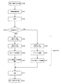
次に、本発明の画像形成装置における転写−定着プロセスの制御を説明する。図4は本発明の実施の形態に係る画像形成装置の転写−定着プロセスのフローを示す図である。なお、このようなフローは不図示の画像形成装置のコントローラによって実行されるものである。 Next, control of the transfer-fixing process in the image forming apparatus of the present invention will be described. FIG. 4 is a diagram showing a flow of a transfer-fixing process of the image forming apparatus according to the embodiment of the present invention. Such a flow is executed by a controller of an image forming apparatus (not shown).
なお、以下、上質紙などのキャリアの吸収性のよい記録媒体をS2、コート紙などのキャリアの吸収性が上質紙より悪い記録媒体をS1とする。 Hereinafter, a recording medium having good carrier absorbency such as high-quality paper will be referred to as S2, and a recording medium having carrier absorption such as coated paper being worse than that of high-quality paper as S1.
また、図4において、ステップS104乃至ステップS107、ステップS108乃至ステップS110は転写プロセスにおける動作を示している。 In FIG. 4, steps S104 to S107 and steps S108 to S110 show operations in the transfer process.
図4において、ステップS100で、転写―定着プロセスが開始さると、次に
ステップS101に進み、紙種判定センサ5によって記録媒体の種別の検出が行われる。次に、ステップS102では、二次転写ユニット60において、中間転写体40から記録媒体へとトナー像の転写が行われる。
In FIG. 4, when the transfer-fixing process is started in step S100, the process advances to step S101, and the paper type determination sensor 5 detects the type of the recording medium. Next, in step S <b> 102, the toner image is transferred from the
ステップS103では、紙種判定センサ5によって取得された信号に基づいて記録媒体がS1であるか否かが判定される。ステップS103における判定の結果がYESであるときには、ステップS104に進み、ステップS103における判定の結果がNOであるときには、ステップS108に進む。 In step S103, it is determined based on the signal acquired by the paper type determination sensor 5 whether the recording medium is S1. When the result of determination in step S103 is YES, the process proceeds to step S104, and when the result of determination in step S103 is NO, the process proceeds to step S108.
ステップS104に進むということは、記録媒体は吸収性がよくないコート紙である場合なので、ステップS104において、第1ローラ対におけるハロゲンランプ73、74をオンし、ステップS105で、本定着用の第2ローラ対におけるハロゲンランプ93、94をオンする。
Proceeding to step S104 means that the recording medium is coated paper that does not absorb well. Therefore, in step S104, the
そして、ステップS106では、第1ローラ対71、72の当接状態を維持し、ステップS107では、キャリア除去ローラ対81、82の当接状態を維持する。
In step S106, the contact state of the
ステップS111で、上記のような当接状態のもとでキャリアを除去した後記録媒体S1にトナー像を定着ユニット90で定着する。ステップS112で転写―定着プロセスを終了とする。
In step S111, the carrier is removed under the contact state as described above, and then the toner image is fixed on the recording medium S1 by the fixing
また、ステップS108に進むということは、記録媒体は吸収性がよい上質紙である場合なので、ステップS108では、本定着用の第2ローラ対におけるハロゲンランプ93、94をオンする。
Further, the process proceeds to step S108 because the recording medium is a high-quality paper having good absorbability. In step S108, the
そして、ステップS109では、第1ローラ対71、72を離間させ、ステップS110では、キャリア除去ローラ対81、82を離間させる。以上のような離間状態として、キャリアを除去することなく、ステップS111で定着ユニット90での定着動作を実行する。ステップS112で転写―定着プロセスを終了する。
In step S109, the
このような制御によって本発明の画像形成装置では、記録媒体S1、S2などの紙種に応じて、定着ユニット90でキャリア除去プロセスを実施するので、本定着時にオフセットによる画像欠陥を引き起こす可能性がない。
By such control, in the image forming apparatus of the present invention, the carrier removal process is performed by the fixing
また、本実施形態では、第1ローラ対71、72における第1ニップ圧力と、第2ローラ対91、92における第2ニップ圧力との間には、
(第2ニップ圧力)>(第1ニップ圧力)
が成り立つように設定する。これは、第2ローラ対91、92における定着が本定着であり大きな圧力が必要であるのに対して、第1ローラ対71、72では、第1ローラ対71、72が記録媒体に伝熱効率よく密着できる程度の最低限の圧力があればよいことに起因している。
Further, in the present embodiment, between the first nip pressure in the
(Second nip pressure)> (first nip pressure)
Set so that. This is because the fixing in the
同じように、本実施形態では、第1ローラ対71、72における第1ニップ温度と、該第2ローラ対91、92における第2ニップ温度との間には、
(第2ニップ温度)>(第1ニップ温度)
が成り立つように設定する。これは、第2ローラ対91、92における定着が本定着であり高い温度が必要であるのに対して、第2ローラ対91、92では後段のキャリア除去プロセスのためにキャリアを浮かび上がらせる程度の温度があればよいことに起因している。
Similarly, in this embodiment, between the first nip temperature in the
(Second nip temperature)> (first nip temperature)
Set so that. This is because the fixing at the
次に、実施例について説明する。本実施例では、記録媒体S1の塗工紙(コート紙)としては三菱製紙製:パールコート紙(商品名)を用い、また、記録媒体S2の上質紙としては三菱製紙製:金菱(商品名)を用いた。 Next, examples will be described. In the present embodiment, Mitsubishi Paper: Pearl coated paper (trade name) is used as the coated paper (coated paper) of the recording medium S1, and Mitsubishi Paper: Kinryo (product) as the high quality paper of the recording medium S2. Name).
紙種判定センサ5により紙種類を判別し、紙種類が記録媒体S2(金菱(三菱製紙製))である場合は、第1ローラ対71、72とキャリア除去ローラ対81、82を離間させた後、記録媒体を搬送し、第2ローラ対91、92により加熱定着を行う。紙種類が記録媒体S1(パールコート紙(三菱製紙製))である場合は、第1ローラ対71、72とキャリア除去手段を当接させた後、記録媒体を搬送し、第1ローラ対71、72により記録媒体を予備加熱した後浮かび上がらせたキャリアをキャリア除去ローラ対81、82にて除去した後、第2ローラ対91、92により加熱定着を行った。第1ローラ対71、72及び第2ローラ対91、92におけるそれぞれの温度、線圧に係る条件を図5に示す。
When the paper type is determined by the paper type determination sensor 5 and the paper type is the recording medium S2 (Kinryo (Mitsubishi Paper)), the
記録媒体はその表層の状態によりキャリアの吸収性が異なるが、キャリアの吸収性が低い記録媒体S1(パールコート紙(三菱製紙製))では、定着突入時に紙上に過剰なキャリアが残存し、該キャリアが固形分と用紙の間に介在し定着不良を引き起こすことがある。そのような記録媒体において高定着率を得るには、紙上のキャリアを除去する必要がある。また一方、キャリアの吸収性が高い記録媒体S2(金菱(三菱製紙製))では、転写後、定着に突入する時には、キャリアの吸収はほぼ終わっており、キャリアが定着率に与える影響は殆ど無い。そのようなキャリアの吸収性の高い用紙でキャリア除去を行った場合は、画像乱れを起こしたり、キャリアを過剰に取りすぎることにより離型剤の役割を果たすキャリアが無くなってしまい、オフセットを発生する可能性がある。 Although the recording medium has different carrier absorbency depending on the state of its surface layer, in the recording medium S1 (pearl coated paper (manufactured by Mitsubishi Paper Industries)) having low carrier absorbency, excess carrier remains on the paper at the time of entry into the fixing medium. The carrier may be interposed between the solid content and the paper to cause poor fixing. In order to obtain a high fixing rate in such a recording medium, it is necessary to remove the carrier on the paper. On the other hand, in the recording medium S2 (Kinryo (Mitsubishi Paper)) having a high carrier absorbability, the carrier absorption is almost finished when entering the fixing after transfer, and the carrier has almost no influence on the fixing rate. No. If the carrier is removed with such a carrier-absorbing paper, the image will be distorted or the carrier acting as a release agent will be lost due to excessive carrier removal, resulting in an offset. there is a possibility.
本発明によれば、記録媒体のキャリア吸収性に応じ、予備加熱後にキャリア除去を行うというプロセスの適用の有無を切り替えることができ、記録媒体の種類によらず、画像乱れが無く、良好な定着率の画像を得ることができる。 According to the present invention, according to the carrier absorbability of the recording medium, it is possible to switch the application of the process of removing the carrier after the preheating, and there is no image disturbance regardless of the type of the recording medium, and good fixing. Rate images can be obtained.
次に、定着ユニット90におけるバイアス印加について説明する。図6は本発明の他の実施の形態に係る画像形成装置の定着ユニットでのバイアス印加を示す図である。本実施形態は、定着ユニット90でバイアス電圧が印加されること以外は、先の実施形態と同様である。
Next, bias application in the fixing
図6に示すように、第1ローラ71にはバイアス電圧が印加されると共に、第1ローラ72は接地されている。このバイアス電圧は、記録媒体上のトナー像を第1ローラ72の方向にトナー粒子を付勢するものとなっており、第1ローラ71へのトナー粒子のオフセットを防止することができる。
As shown in FIG. 6, a bias voltage is applied to the
このような実施形態によれば、第1ローラ対71、72にはバイアスがかかった状態で接触方式の加熱を行い、キャリアを浮かび上がらせるので、オフセット無くキャリアを除去することができ画質を乱すことがない。
According to such an embodiment, the
次に、本発明の他の実施の形態に係る画像形成装置について説明する。図7は本発明の他の実施の形態に係る画像形成装置の定着ユニットの構成を示す図である。図7の実施形態が先の実施形態と異なる点は、キャリア除去手段の構成であり、その他の構成は先のものと同じである。 Next, an image forming apparatus according to another embodiment of the present invention will be described. FIG. 7 is a diagram showing a configuration of a fixing unit of an image forming apparatus according to another embodiment of the present invention. The embodiment of FIG. 7 differs from the previous embodiment in the configuration of the carrier removing means, and the other configuration is the same as the previous embodiment.
本実施形態では、キャリア除去手段が、用紙ガイド83と、この用紙ガイド83に記録媒体を押し当てキャリア除去を行うキャリア除去ローラ84とから構成されている。図7に示すように、第1ローラ対71、72及びキャリア除去ローラ84は不図示の機構によって紙搬送経路Lから移動可能に形成されている。
In the present embodiment, the carrier removing means includes a
図7(a)は第1ローラ対71、72及びキャリア除去ローラ84が紙搬送経路Lに最接近し、紙搬送経路で搬送される記録媒体に当接しえる状態を示しており、図7(b)は第1ローラ対71、72及びキャリア除去ローラ84が紙搬送経路Lから離れ、紙搬送経路で搬送される記録媒体とは非接触状態となることを示している。
FIG. 7A shows a state in which the
このような実施形態においても、記録媒体の紙種(上質紙、コート紙など)に応じて、キャリア除去プロセスを実施することができ、本定着時にオフセットによる画像欠陥を引き起こす可能性がない。 Also in such an embodiment, the carrier removal process can be performed according to the paper type of the recording medium (quality paper, coated paper, etc.), and there is no possibility of causing an image defect due to offset during the main fixing.
次に、本発明の実施の形態に係る画像形成装置の画像形成部及び現像ユニットについて説明する。図2は画像形成部及び現像ユニットの主要構成要素を示した断面図である。各色の画像形成部及び現像ユニットの構成は同様であるので、以下、イエロー(Y)の画像形成部及び現像ユニットに基づいて説明する。 Next, the image forming unit and the developing unit of the image forming apparatus according to the embodiment of the present invention will be described. FIG. 2 is a cross-sectional view showing main components of the image forming unit and the developing unit. Since the configurations of the image forming unit and the developing unit for each color are the same, the following description will be made based on the yellow (Y) image forming unit and the developing unit.
画像形成部は、像担持体10Yの外周の回転方向に沿って、潜像イレーサ16Y、像担持体クリーニングブレード17Y及び現像剤回収部18Yからなるクリーニング装置、帯電ローラ11Y、露光ユニット12Y、現像ユニット30Yの現像ローラ20Y、像担持体スクイーズローラ13Yとその付属構成である像担持体スクイーズローラクリーニングブレード14Y、現像剤回収部15Yからなるクリーニング装置が配置されている。
The image forming unit includes a cleaning device including a
そして、現像ユニット30Yは、現像ローラ20Yの外周に、クリーニングブレード21Y、アニロックスローラ32Y、トナー圧縮ローラ22Yが配置されている。また、このトナー圧縮ローラ22Yの外周には、キャリア量調整ブレード23Yが設けられている。さらに、液体現像剤容器31Yの中に液体現像剤供給ローラ34Y、アニロックスローラ32Yが収容されている。
In the developing unit 30Y, a
また、中間転写体40に沿って、像担持体10Yと対向する位置に一次転写部の一次転写ローラ51Yが配置され、その移動方向下流側に中間転写体スクイーズローラ53Y、バックアップローラ54Y、中間転写体スクイーズローラクリーニングブレード55Y、現像剤回収部56Yからなる中間転写体スクイーズ装置52Yが配置されている。
A
像担持体10Yは、現像ローラ20Yの幅より広く、外周面に感光層が形成された円筒状の部材からなる感光体ドラムであり、例えば図2に示すように時計回りの方向に回転する。該像担持体10Yの感光層は、有機像担持体又はアモルファスシリコン像担持体等で構成される。帯電ローラ11Yは、像担持体10Yと現像ローラ20Yとのニップ部より像担持体10Yの回転方向の上流側に配置され、図示しない電源装置からトナー帯電極性と同極性のバイアスが印加され、像担持体10Yを帯電させる。露光ユニット12Yは、帯電ローラ11Yより像担持体10Yの回転方向の下流側において、帯電ローラ11Yによって帯電された像担持体10Y上にレーザ光を照射し、像担持体10Y上に潜像を形成する。
The image carrier 10Y is a photosensitive drum made of a cylindrical member that is wider than the developing roller 20Y and has a photosensitive layer formed on the outer peripheral surface thereof. For example, the image carrier 10Y rotates in a clockwise direction as shown in FIG. The photosensitive layer of the image carrier 10Y is composed of an organic image carrier or an amorphous silicon image carrier. The charging
現像ユニット30Yは、トナー圧縮ローラ22Y、キャリア内にトナーを概略重量比20%程度に分散した状態の液体現像剤を貯蔵する現像剤容器31Y、該液体現像剤を担持する現像ローラ20Y、液体現像剤を攪拌して一様の分散状態に維持し現像ローラ20Yに供給するためのアニロックスローラ32Yと規制ブレード33Yと供給ローラ34Y、現像ローラ20Yに担持された液体現像剤をコンパクション状態にするトナー圧縮ローラ22Y、現像ローラ20Yのクリーニングを行う現像ローラクリーニングブレード21Yを有する。
The developing unit 30Y includes a
現像剤容器31Yに収容されている液体現像剤は、従来一般的に使用されている、Isopar(商標:エクソン)をキャリアとした低濃度(1〜2wt%程度)かつ低粘度の、常温で揮発性を有する揮発性液体現像剤ではなく、高濃度かつ高粘度の、常温で不揮発性を有する不揮発性液体現像剤である。すなわち、本発明における液体現像剤は、熱可塑性樹脂中へ顔料等の着色剤を分散させた平均粒径1μmの固形子を、有機溶媒、シリコンオイル、鉱物油又は食用油等の液体溶媒中へ分散剤とともに添加し、トナー固形分濃度を約20%とした高粘度(30〜10000mPa・s程度)の液体現像剤である。
The liquid developer accommodated in the
アニロックスローラ32Yは、円筒状の部材であり、表面に現像剤を担持し易いように表面に微細且つ一様に螺旋状の溝による凹凸面を形成したローラである。この溝の寸法は、溝ピッチが約130μm、溝深さが約30μmである。このアニロックスローラ32Yにより、現像剤容器31Yから現像ローラ20Yへと液体現像剤が供給される。後述する交流バイアスの効果を最大限にするため、アニロックスローラ32Yと供給ローラ34Yは同一回転方向で、それぞれが接触している状態が望ましい。
The
規制ブレード33Yは、表面に弾性体を被覆して構成した弾性ブレード、アニロックスローラ32Yの表面に当接するウレタンゴム等からなるゴム部と、該ゴム部を支持する金属等の板で構成される。そして、アニロックスローラからなるアニロックスローラ32Yに担持搬送されてきた液体現像剤の膜厚、量を規制、調整し、現像ローラ20Yに供給する液体現像剤の量を調整する。
The
現像ローラ20Yは、幅約320mmの円筒状の部材であり、回転軸を中心に図2に示すように反時計回りに回転する。該現像ローラ20Yは鉄等金属製の内芯の外周部に、ポリウレタンゴム、シリコンゴム、NBR等の弾性層を設けたものである。現像ローラクリーニングブレード21Yは、現像ローラ20Yの表面に当接するゴム等で構成され、現像ローラ20Yが像担持体10Yと当接する現像ニップ部より現像ローラ20Yの回転方向の下流側に配置されて、現像ローラ20Yに残存する液体現像剤を掻き落として除去するものである。
The developing roller 20Y is a cylindrical member having a width of about 320 mm, and rotates counterclockwise around the rotation axis as shown in FIG. The developing roller 20Y is provided with an elastic layer made of polyurethane rubber, silicon rubber, NBR or the like on the outer periphery of an inner core made of metal such as iron. The developing
トナー圧縮ローラ22Yは、円筒状の部材で、現像ローラ20Yと同様に弾性体を被覆して構成した弾性ローラの形態であり、金属ローラ基材の表層に導電性の樹脂層やゴム層を備えた構造をし、例えば図2に示すように現像ローラ20Yと反対方向の時計回りに回転する。トナー圧縮ローラ22Yは、現像ローラ20Y表面の帯電バイアスを増加させる手段を有し、現像ローラ20Yによって搬送された現像剤は、図2に示すようにトナー圧縮ローラ22Yが摺接してニップを形成するトナー圧縮部位でトナー圧縮ローラ22Y側から現像ローラ20Yに向かって電界を印加する。このトナー圧縮の電界印加手段は、図2に示すローラに代えコロナ放電器からのコロナ放電であっても良い。キャリアの一部とトナー圧縮されなかった若干のトナーはキャリア量調整ブレード23Yによって掻き落として除去されリザーバ31Y内の現像剤と合流して再利用される。
The
一方、現像ローラ20Yに担持されてトナー圧縮された現像剤は、現像ローラ20Yが像担持体10Yに当接する現像ニップ部において、所望の電界印加によって、像担持体10Yの潜像に対応して現像される。そして、現像残りの現像剤は、現像ローラクリーニングブレード21Yによって掻き落として除去されリザーバ31Y内の現像剤に合流して再利用される。尚、これら合流するキャリア及びトナーは混色状態ではない。
On the other hand, the developer compressed by toner carried on the developing roller 20Y corresponds to the latent image on the image carrier 10Y by applying a desired electric field at the development nip where the developing roller 20Y contacts the image carrier 10Y. Developed. The developer remaining after development is scraped off and removed by the developing
像担持体スクイーズ装置は、像担持体10Yに対向して現像器20Yの下流側に配置して像担持体10Yに現像されたトナー像の余剰現像剤を回収するものであり、図2に示すように表面に弾性体を被覆して像担持体10Yに摺接して回転する弾性ローラ部材から成る像担持体スクイーズローラ13Yと、該像担持体スクイーズローラ13Yに押圧摺接して表面をクリーニングするクリーニングブレード14Yとから構成され、像担持体10Yに現像された現像剤から余剰なキャリア及び本来不要なカブリトナーを回収し、顕像内のトナー粒子比率を上げる機能を有する。
The image carrier squeeze device is disposed on the downstream side of the developing device 20Y so as to face the image carrier 10Y and collects the excess developer of the toner image developed on the image carrier 10Y, as shown in FIG. In this way, the image
一次転写部50Yでは、像担持体10Yに現像された現像剤像を一次転写ローラ51Yにより中間転写体40へ転写する。ここで、像担持体10Yと中間転写体40は等速度で移動する構成であり、回転及び移動の駆動負荷を軽減するとともに、像担持体10Yの顕像トナー像への外乱作用を抑制している。
In the
中間転写体スクイーズ装置52Yは、一次転写部50Yの下流側に配置され、中間転写体40上から余剰なキャリア液を除去し、顕像内のトナー粒子比率を上げる処理を行うものである。
The intermediate transfer
中間転写体スクイーズ装置52Yは、像担持体スクイーズ装置と同様、表面に弾性体を被覆して像担持体40に摺接して回転する弾性ローラ部材から成る中間転写体スクイーズローラ53Y、像担持体40を挟んで中間転写体スクイーズローラ53Yと対向配置されるバックアップローラ54Y、中間転写体スクイーズローラ53Yに押圧摺接して表面をクリーニングするクリーニングブレード55Y及び現像剤回収部56Yから構成され、中間転写体40に一次転写された現像剤から余剰なキャリア及び本来不要なカブリトナーを回収する機能を有する。現像剤回収部56Yは、その下流側に配置されたマゼンタの像担持体スクイーズローラクリーニングブレード14Mで回収されるキャリア液の回収機構も兼ねている。
Similar to the image carrier squeeze device 52, the intermediate transfer
以上、本発明によれば、接触方式の加熱手段によって浮かび上がらせたキャリア溶媒を除去するものであるので、効率的な熱伝達による省電力化と装置のコンパクト化を実現することができる。 As described above, according to the present invention, since the carrier solvent that has been lifted by the contact-type heating means is removed, it is possible to realize power saving and efficient device compaction by efficient heat transfer.
また、接触方式の加熱手段では未定着画像を均一に加熱し、均一にキャリアを浮かび上がらせることができるので、定着時の画質ムラが生じない。 Further, the contact-type heating means can uniformly heat the unfixed image and uniformly lift the carrier, so that image quality unevenness during fixing does not occur.
また、バイアスがかかった状態で接触方式の加熱を行い、キャリアを浮かび上がらせるので、オフセット無くキャリアを除去することができ画質を乱すことがない。 In addition, contact-type heating is performed in a biased state, and the carrier is lifted, so that the carrier can be removed without offset and image quality is not disturbed.
また、記録媒体の紙種(上質紙、コート紙など)に応じて、キャリアの除去を行うので、本定着時にオフセットによる画像欠陥を引き起こす可能性がない。 In addition, since the carrier is removed according to the paper type of the recording medium (quality paper, coated paper, etc.), there is no possibility of causing image defects due to offset during the main fixing.
なお、本明細書においては、種々の実施の形態について説明したが、それぞれの実施の形態の構成を適宜組み合わせて構成された実施形態も本発明の範疇となるものである。 Note that although various embodiments have been described in this specification, embodiments configured by appropriately combining the configurations of the respective embodiments are also included in the scope of the present invention.
5・・・紙種判定センサ、6・・・発光素子、7・・・受光素子、10Y、10M、10C、10K・・・像担持体、11Y、11M、11C、11K・・・帯電ローラ、12Y、12M、12C、12K・・・露光ユニット、13Y・・・像担持体スクイーズローラ、14Y・・・像担持体スクイーズローラクリーニングブレード、15Y・・・現像剤回収部、16Y・・・潜像イレーサ、17Y・・・像担持体クリーニングブレード、18Y・・・現像剤回収部、20Y、20M、20C、20K・・・現像ローラ、21Y・・・現像ローラクリーニングブレード、22Y・・・トナー圧縮ローラ、23Y・・・キャリア量調整ブレード、24Y・・・キャリア量調整ローラ、25Y・・・キャリア量調整エアナイフ、30Y、30M、30C、30K・・・現像ユニット、31Y、31M、31C、31K・・・現像剤容器、32Y、32M、32C、32K・・・アニロックスローラ、31Y、31M、31C、31K・・・現像剤容器、33Y・・・規制ブレード、34Y・・・供給ローラ、40・・・中間転写体、41・・・ベルト駆動ローラ、42・・・テンションローラ、45・・・現像剤回収部、46・・・中間転写体クリーニングブレード、47・・・現像剤回収部、50Y、50M、50C、50K・・・一次転写部、51Y、51M、51C、51K・・・一次転写バックアップローラ、52Y、52M、52C、52K・・・中間転写体スクイーズユニット、53Y・・・中間転写体スクイーズローラ、54Y・・・中間転写体スクイーズバックアップローラ、55Y・・・中間転写体スクイーズローラクリーニングブレード、56Y・・・現像剤回収部、60・・・二次転写ユニット、61・・・二次転写ローラ、62・・・二次転写ローラクリーニングブレード、63・・・現像剤回収部、71、72・・・第1ローラ対、73、74・・・ハロゲンランプ、81、82・・・キャリア除去ローラ対、83・・・用紙ガイド83、84・・・キャリア除去ローラ、91、92・・・第2ローラ対、93、94・・・ハロゲンランプ
5 ... paper type determination sensor, 6 ... light emitting element, 7 ... light receiving element, 10Y, 10M, 10C, 10K ... image carrier, 11Y, 11M, 11C, 11K ... charging roller, 12Y, 12M, 12C, 12K ... exposure unit, 13Y ... image carrier squeeze roller, 14Y ... image carrier squeeze roller cleaning blade, 15Y ... developer recovery unit, 16Y ... latent image Eraser, 17Y ... image carrier cleaning blade, 18Y ... developer recovery unit, 20Y, 20M, 20C, 20K ... developing roller, 21Y ... developing roller cleaning blade, 22Y ... toner compression roller , 23Y ... Carrier amount adjusting blade, 24Y ... Carrier amount adjusting roller, 25Y ... Carrier amount adjusting air knife, 30Y, 30M, 0C, 30K: Development unit, 31Y, 31M, 31C, 31K ... Developer container, 32Y, 32M, 32C, 32K ... Anilox roller, 31Y, 31M, 31C, 31K ... Developer container, 33Y: restriction blade, 34Y: supply roller, 40 ... intermediate transfer member, 41 ... belt drive roller, 42 ... tension roller, 45 ... developer recovery unit, 46 ... Intermediate transfer member cleaning blade, 47... Developer recovery unit, 50Y, 50M, 50C, 50K ... primary transfer unit, 51Y, 51M, 51C, 51K ... primary transfer backup roller, 52Y, 52M, 52C, 52K: Intermediate transfer member squeeze unit, 53Y: Intermediate transfer member squeeze roller, 54Y: Intermediate transfer
Claims (8)
該第1ローラ対の下流に設けられ予熱された記録媒体上のトナー像からキャリアを除去するキャリア除去手段と、
該キャリア除去手段の下流に設けられ記録媒体上のトナー像を融着する第2ローラ対と、を有し、
該第1ローラ対及び該キャリア除去手段は記録媒体の搬送経路に対して移動可能に構成されることを特徴とする定着装置。 A first roller pair for preheating the recording medium on which the toner image is transferred together with the carrier;
Carrier removing means for removing the carrier from the toner image on the preheated recording medium provided downstream of the first roller pair;
A second roller pair provided downstream of the carrier removing means for fusing the toner image on the recording medium,
The fixing device according to claim 1, wherein the first roller pair and the carrier removing unit are configured to be movable with respect to a conveyance path of the recording medium.
(第2ニップ圧力)>(第1ニップ圧力)
の関係を有することを特徴とする請求項1乃至請求項4のいずれかに記載の定着装置。 Between the first nip pressure in the first roller pair and the second nip pressure in the second roller pair,
(Second nip pressure)> (first nip pressure)
The fixing device according to claim 1, wherein the fixing device has the following relationship.
(第2ニップ温度)>(第1ニップ温度)
の関係を有することを特徴とする請求項1乃至請求項5のいずれかに記載の定着装置。 Between the first nip temperature in the first roller pair and the second nip temperature in the second roller pair,
(Second nip temperature)> (first nip temperature)
The fixing device according to claim 1, wherein the fixing device has the following relationship.
該紙種判定手段の判定結果に基づいて該第1ローラ対及び該キャリア除去手段を記録媒体の搬送経路に対して移動することを特徴とする請求項1乃至請求項6のいずれかに記載の定着装置を用いたことを特徴とする画像形成装置。 A paper type determining means for determining the type of recording medium to be fixed by the fixing device;
7. The method according to claim 1, wherein the first roller pair and the carrier removal unit are moved with respect to the conveyance path of the recording medium based on a determination result of the paper type determination unit. An image forming apparatus using a fixing device.
判定の結果に応じ本定着の上流で、キャリアと共にトナー像が転写された記録媒体を予熱しキャリアを除去するかしないかを決定することを特徴とする画像形成方法。 Determine the type of recording medium to be fixed,
An image forming method comprising: preheating a recording medium on which a toner image has been transferred together with a carrier and determining whether or not to remove the carrier upstream of the main fixing in accordance with a determination result.
Priority Applications (1)
| Application Number | Priority Date | Filing Date | Title |
|---|---|---|---|
| JP2007265148A JP2009093039A (en) | 2007-10-11 | 2007-10-11 | Fixing device, image forming apparatus using the same, and an image forming method |
Applications Claiming Priority (1)
| Application Number | Priority Date | Filing Date | Title |
|---|---|---|---|
| JP2007265148A JP2009093039A (en) | 2007-10-11 | 2007-10-11 | Fixing device, image forming apparatus using the same, and an image forming method |
Publications (1)
| Publication Number | Publication Date |
|---|---|
| JP2009093039A true JP2009093039A (en) | 2009-04-30 |
Family
ID=40665065
Family Applications (1)
| Application Number | Title | Priority Date | Filing Date |
|---|---|---|---|
| JP2007265148A Pending JP2009093039A (en) | 2007-10-11 | 2007-10-11 | Fixing device, image forming apparatus using the same, and an image forming method |
Country Status (1)
| Country | Link |
|---|---|
| JP (1) | JP2009093039A (en) |
Cited By (4)
| Publication number | Priority date | Publication date | Assignee | Title |
|---|---|---|---|---|
| JP2013120330A (en) * | 2011-12-08 | 2013-06-17 | Konica Minolta Business Technologies Inc | Fixing device and image forming apparatus |
| JP2015138202A (en) * | 2014-01-23 | 2015-07-30 | 富士ゼロックス株式会社 | Image forming apparatus, program, and image forming method |
| JP2015184367A (en) * | 2014-03-20 | 2015-10-22 | 富士ゼロックス株式会社 | Removal apparatus, fixing apparatus, and image forming apparatus |
| JP2015194679A (en) * | 2014-03-20 | 2015-11-05 | 富士ゼロックス株式会社 | image forming apparatus |
-
2007
- 2007-10-11 JP JP2007265148A patent/JP2009093039A/en active Pending
Cited By (4)
| Publication number | Priority date | Publication date | Assignee | Title |
|---|---|---|---|---|
| JP2013120330A (en) * | 2011-12-08 | 2013-06-17 | Konica Minolta Business Technologies Inc | Fixing device and image forming apparatus |
| JP2015138202A (en) * | 2014-01-23 | 2015-07-30 | 富士ゼロックス株式会社 | Image forming apparatus, program, and image forming method |
| JP2015184367A (en) * | 2014-03-20 | 2015-10-22 | 富士ゼロックス株式会社 | Removal apparatus, fixing apparatus, and image forming apparatus |
| JP2015194679A (en) * | 2014-03-20 | 2015-11-05 | 富士ゼロックス株式会社 | image forming apparatus |
Similar Documents
| Publication | Publication Date | Title |
|---|---|---|
| JP2009093039A (en) | Fixing device, image forming apparatus using the same, and an image forming method | |
| JP2009175696A (en) | Image forming apparatus and method for controlling image forming apparatus | |
| JP2008090116A (en) | Image forming apparatus and image forming method | |
| JP2008090116A5 (en) | ||
| JP2009098474A (en) | Image forming apparatus and image forming method | |
| JP2009098475A (en) | Fixing device, image forming apparatus using the same and image forming method | |
| JP2007147974A (en) | Image forming apparatus | |
| JP2010054751A (en) | Fixing device and image forming apparatus | |
| JP2008090113A (en) | Image forming apparatus and image forming method | |
| JP2007114392A (en) | Image forming apparatus | |
| JP5177381B2 (en) | Image forming apparatus and image forming method | |
| JP4849214B2 (en) | Developing device and image forming apparatus | |
| JP4636293B2 (en) | Developing device and image forming apparatus | |
| JP2009093038A (en) | Image forming apparatus and image forming method | |
| JP4573044B2 (en) | Developing device and image forming apparatus | |
| JP2008090114A (en) | Fixing device and image forming method | |
| JP2007114380A (en) | Developing system for liquid development and developing method for liquid development | |
| JP2009098473A (en) | Fixing roller, fixing device using same, and image forming device | |
| JP2009093040A (en) | Transfer apparatus, image forming apparatus using the same, and image forming method | |
| JP2007114382A (en) | Image forming apparatus and image forming method | |
| JP2008102415A (en) | Developing device and image forming apparatus using the same | |
| JP2007155997A (en) | Developing system for liquid development and developing method for liquid development | |
| JP2007155996A (en) | Developing system for liquid development and developing method for liquid development | |
| JP2010060767A (en) | Fixing device and image forming apparatus | |
| JP4807494B2 (en) | Developing device, image forming apparatus, and image forming method |