JP2009089304A - Portable terminal device - Google Patents
Portable terminal device Download PDFInfo
- Publication number
- JP2009089304A JP2009089304A JP2007259609A JP2007259609A JP2009089304A JP 2009089304 A JP2009089304 A JP 2009089304A JP 2007259609 A JP2007259609 A JP 2007259609A JP 2007259609 A JP2007259609 A JP 2007259609A JP 2009089304 A JP2009089304 A JP 2009089304A
- Authority
- JP
- Japan
- Prior art keywords
- display
- sub
- sub display
- terminal device
- holder
- Prior art date
- Legal status (The legal status is an assumption and is not a legal conclusion. Google has not performed a legal analysis and makes no representation as to the accuracy of the status listed.)
- Pending
Links
Images


Classifications
-
- H—ELECTRICITY
- H04—ELECTRIC COMMUNICATION TECHNIQUE
- H04M—TELEPHONIC COMMUNICATION
- H04M1/00—Substation equipment, e.g. for use by subscribers
- H04M1/02—Constructional features of telephone sets
- H04M1/0202—Portable telephone sets, e.g. cordless phones, mobile phones or bar type handsets
- H04M1/026—Details of the structure or mounting of specific components
- H04M1/0266—Details of the structure or mounting of specific components for a display module assembly
-
- G—PHYSICS
- G02—OPTICS
- G02F—OPTICAL DEVICES OR ARRANGEMENTS FOR THE CONTROL OF LIGHT BY MODIFICATION OF THE OPTICAL PROPERTIES OF THE MEDIA OF THE ELEMENTS INVOLVED THEREIN; NON-LINEAR OPTICS; FREQUENCY-CHANGING OF LIGHT; OPTICAL LOGIC ELEMENTS; OPTICAL ANALOGUE/DIGITAL CONVERTERS
- G02F1/00—Devices or arrangements for the control of the intensity, colour, phase, polarisation or direction of light arriving from an independent light source, e.g. switching, gating or modulating; Non-linear optics
- G02F1/01—Devices or arrangements for the control of the intensity, colour, phase, polarisation or direction of light arriving from an independent light source, e.g. switching, gating or modulating; Non-linear optics for the control of the intensity, phase, polarisation or colour
- G02F1/13—Devices or arrangements for the control of the intensity, colour, phase, polarisation or direction of light arriving from an independent light source, e.g. switching, gating or modulating; Non-linear optics for the control of the intensity, phase, polarisation or colour based on liquid crystals, e.g. single liquid crystal display cells
- G02F1/133—Constructional arrangements; Operation of liquid crystal cells; Circuit arrangements
- G02F1/1333—Constructional arrangements; Manufacturing methods
- G02F1/133308—Support structures for LCD panels, e.g. frames or bezels
-
- H—ELECTRICITY
- H04—ELECTRIC COMMUNICATION TECHNIQUE
- H04M—TELEPHONIC COMMUNICATION
- H04M1/00—Substation equipment, e.g. for use by subscribers
- H04M1/02—Constructional features of telephone sets
- H04M1/18—Telephone sets specially adapted for use in ships, mines, or other places exposed to adverse environment
- H04M1/185—Improving the rigidity of the casing or resistance to shocks
-
- G—PHYSICS
- G02—OPTICS
- G02F—OPTICAL DEVICES OR ARRANGEMENTS FOR THE CONTROL OF LIGHT BY MODIFICATION OF THE OPTICAL PROPERTIES OF THE MEDIA OF THE ELEMENTS INVOLVED THEREIN; NON-LINEAR OPTICS; FREQUENCY-CHANGING OF LIGHT; OPTICAL LOGIC ELEMENTS; OPTICAL ANALOGUE/DIGITAL CONVERTERS
- G02F1/00—Devices or arrangements for the control of the intensity, colour, phase, polarisation or direction of light arriving from an independent light source, e.g. switching, gating or modulating; Non-linear optics
- G02F1/01—Devices or arrangements for the control of the intensity, colour, phase, polarisation or direction of light arriving from an independent light source, e.g. switching, gating or modulating; Non-linear optics for the control of the intensity, phase, polarisation or colour
- G02F1/13—Devices or arrangements for the control of the intensity, colour, phase, polarisation or direction of light arriving from an independent light source, e.g. switching, gating or modulating; Non-linear optics for the control of the intensity, phase, polarisation or colour based on liquid crystals, e.g. single liquid crystal display cells
- G02F1/133—Constructional arrangements; Operation of liquid crystal cells; Circuit arrangements
- G02F1/1333—Constructional arrangements; Manufacturing methods
- G02F1/133308—Support structures for LCD panels, e.g. frames or bezels
- G02F1/133311—Environmental protection, e.g. against dust or humidity
-
- G—PHYSICS
- G02—OPTICS
- G02F—OPTICAL DEVICES OR ARRANGEMENTS FOR THE CONTROL OF LIGHT BY MODIFICATION OF THE OPTICAL PROPERTIES OF THE MEDIA OF THE ELEMENTS INVOLVED THEREIN; NON-LINEAR OPTICS; FREQUENCY-CHANGING OF LIGHT; OPTICAL LOGIC ELEMENTS; OPTICAL ANALOGUE/DIGITAL CONVERTERS
- G02F1/00—Devices or arrangements for the control of the intensity, colour, phase, polarisation or direction of light arriving from an independent light source, e.g. switching, gating or modulating; Non-linear optics
- G02F1/01—Devices or arrangements for the control of the intensity, colour, phase, polarisation or direction of light arriving from an independent light source, e.g. switching, gating or modulating; Non-linear optics for the control of the intensity, phase, polarisation or colour
- G02F1/13—Devices or arrangements for the control of the intensity, colour, phase, polarisation or direction of light arriving from an independent light source, e.g. switching, gating or modulating; Non-linear optics for the control of the intensity, phase, polarisation or colour based on liquid crystals, e.g. single liquid crystal display cells
- G02F1/133—Constructional arrangements; Operation of liquid crystal cells; Circuit arrangements
- G02F1/1333—Constructional arrangements; Manufacturing methods
- G02F1/133308—Support structures for LCD panels, e.g. frames or bezels
- G02F1/133314—Back frames
-
- G—PHYSICS
- G02—OPTICS
- G02F—OPTICAL DEVICES OR ARRANGEMENTS FOR THE CONTROL OF LIGHT BY MODIFICATION OF THE OPTICAL PROPERTIES OF THE MEDIA OF THE ELEMENTS INVOLVED THEREIN; NON-LINEAR OPTICS; FREQUENCY-CHANGING OF LIGHT; OPTICAL LOGIC ELEMENTS; OPTICAL ANALOGUE/DIGITAL CONVERTERS
- G02F1/00—Devices or arrangements for the control of the intensity, colour, phase, polarisation or direction of light arriving from an independent light source, e.g. switching, gating or modulating; Non-linear optics
- G02F1/01—Devices or arrangements for the control of the intensity, colour, phase, polarisation or direction of light arriving from an independent light source, e.g. switching, gating or modulating; Non-linear optics for the control of the intensity, phase, polarisation or colour
- G02F1/13—Devices or arrangements for the control of the intensity, colour, phase, polarisation or direction of light arriving from an independent light source, e.g. switching, gating or modulating; Non-linear optics for the control of the intensity, phase, polarisation or colour based on liquid crystals, e.g. single liquid crystal display cells
- G02F1/133—Constructional arrangements; Operation of liquid crystal cells; Circuit arrangements
- G02F1/1333—Constructional arrangements; Manufacturing methods
- G02F1/133308—Support structures for LCD panels, e.g. frames or bezels
- G02F1/133317—Intermediate frames, e.g. between backlight housing and front frame
-
- G—PHYSICS
- G02—OPTICS
- G02F—OPTICAL DEVICES OR ARRANGEMENTS FOR THE CONTROL OF LIGHT BY MODIFICATION OF THE OPTICAL PROPERTIES OF THE MEDIA OF THE ELEMENTS INVOLVED THEREIN; NON-LINEAR OPTICS; FREQUENCY-CHANGING OF LIGHT; OPTICAL LOGIC ELEMENTS; OPTICAL ANALOGUE/DIGITAL CONVERTERS
- G02F1/00—Devices or arrangements for the control of the intensity, colour, phase, polarisation or direction of light arriving from an independent light source, e.g. switching, gating or modulating; Non-linear optics
- G02F1/01—Devices or arrangements for the control of the intensity, colour, phase, polarisation or direction of light arriving from an independent light source, e.g. switching, gating or modulating; Non-linear optics for the control of the intensity, phase, polarisation or colour
- G02F1/13—Devices or arrangements for the control of the intensity, colour, phase, polarisation or direction of light arriving from an independent light source, e.g. switching, gating or modulating; Non-linear optics for the control of the intensity, phase, polarisation or colour based on liquid crystals, e.g. single liquid crystal display cells
- G02F1/133—Constructional arrangements; Operation of liquid crystal cells; Circuit arrangements
- G02F1/1333—Constructional arrangements; Manufacturing methods
- G02F1/133342—Constructional arrangements; Manufacturing methods for double-sided displays
-
- G—PHYSICS
- G02—OPTICS
- G02F—OPTICAL DEVICES OR ARRANGEMENTS FOR THE CONTROL OF LIGHT BY MODIFICATION OF THE OPTICAL PROPERTIES OF THE MEDIA OF THE ELEMENTS INVOLVED THEREIN; NON-LINEAR OPTICS; FREQUENCY-CHANGING OF LIGHT; OPTICAL LOGIC ELEMENTS; OPTICAL ANALOGUE/DIGITAL CONVERTERS
- G02F2201/00—Constructional arrangements not provided for in groups G02F1/00 - G02F7/00
- G02F2201/50—Protective arrangements
- G02F2201/503—Arrangements improving the resistance to shock
Abstract
Description
本発明は、筐体の両面に液晶表示装置等の表示手段を設けた携帯端末装置に関し、特に筐体の一方の面に大型のいわゆるメインディスプレイを配置し、他方の面に小型のいわゆるサブディスプレイを配置した携帯端末装置に関する。 The present invention relates to a portable terminal device in which display means such as a liquid crystal display device is provided on both sides of a housing, and in particular, a large so-called main display is disposed on one surface of the housing and a small so-called sub-display is disposed on the other surface. It is related with the portable terminal device which has arranged.
従来の折り畳み式携帯電話機のような携帯端末装置では、筐体を開いたときに各種の表示を行なうメインディスプレイを配置する一方で、筐体を折り畳んだ状態でも着信状態や時刻を表示するためのサブディスプレイを配置したものが実用化されている。 In a portable terminal device such as a conventional foldable mobile phone, a main display that performs various displays when the casing is opened is arranged, while an incoming call state and time are displayed even when the casing is folded. A device with a sub-display has been put into practical use.
これら従来の携帯端末装置は、筐体を折り畳んだ状態で着信状態や時刻を確認できるので便利であるが、筐体を折り畳んだ状態でポケットや鞄にいれたり、あるいは手に持って携行したりする。そのため、例えばズボンの後ろポケットに携帯端末装置をいれた状態で座って、携帯端末装置の筐体が押しつけられたり、携帯端末装置を床に落としたりすることがある。これらの場合、筐体を折り畳んだ状態で外表面にあるサブディスプレイにかかる力がメインディスプレイに直接伝わって、メインディスプレイを変形させてしまう。極端な場合は、メインディスプレイを破壊してしまうことがある。 These conventional portable terminal devices are convenient because you can check the incoming call status and time when the case is folded, but you can put it in your pocket or bag with the case folded or carry it in your hand. To do. Therefore, for example, the user may sit down with the portable terminal device in the back pocket of the pants and the casing of the portable terminal device may be pressed or the portable terminal device may be dropped on the floor. In these cases, the force applied to the sub-display on the outer surface with the housing folded is directly transmitted to the main display, and the main display is deformed. In extreme cases, the main display may be destroyed.
そこで、メインディスプレイとサブディスプレイとが上下に積層配置されている移動通信端末用デュアル型LCDモジュールにおいて、メインディスプレイとサブディスプレイとを一定間隔で離間して配置し、両ディスプレイ間に前記メインLCDを覆って保護すると同時にサブディスプレイを支持するブラケットを配置する構成が提案されている。 Therefore, in a dual type LCD module for a mobile communication terminal in which a main display and a sub display are stacked one above the other, the main display and the sub display are spaced apart at a fixed interval, and the main LCD is placed between the two displays. A configuration has been proposed in which a bracket that supports and covers the sub-display at the same time is disposed.
図12に上記従来の携帯端末装置の断面図を示す。図12において、30はメインディスプレイ用筐体を示し、40はサブディスプレイ用筐体を示している。41はメインディスプレイとサブディスプレイを一定間隔で離間して固定するブラケットである。31はメインディスプレイであり、42はサブディスプレイである。メインディスプレイ用筐体30とサブディスプレイ用筐体40には、それぞれメインディスプレイ用透明窓32と、サブディスプレイ用透明窓43を設けている。
FIG. 12 shows a cross-sectional view of the conventional portable terminal device. In FIG. 12,
図12をみれば明らかなように、ブラケット41によってメインディスプレイ31とサブディスプレイ42は、所定間隔だけ引き離されてメインディスプレイ用筐体30とサブディスプレイ用筐体40の中に配置されている。メインディスプレイ31とサブディスプレイ42とが所定間隔だけ引き離されているので、携帯端末装置に衝撃力がかかったとしても、メインディスプレイ31とサブディスプレイ42とが接触することはない。外表面にあるサブディスプレイに加わる力は、ブラケット41で受け止められる。このことにより、従来の携帯端末装置でもメインディスプレイの変形や破壊を防ぐことができる(例えば、特許文献1参照)。
As is apparent from FIG. 12, the
しかし、昨今、携帯電話機をはじめ、多くの携帯端末装置の薄型化が求められるようになってきた。携帯端末装置の薄型化が求められると、上記従来の構造では、メインディスプレイ31とサブディスプレイ42とが衝突しないために必要な間隔を確保することが難しくなる。
Recently, however, many mobile terminal devices such as mobile phones have been required to be thin. When the mobile terminal device is required to be thin, the above-described conventional structure makes it difficult to ensure a necessary interval because the
そこで、他の従来例として、メインディスプレイとサブディスプレイの間に空間を設ける代わりに、図13に示したように、サブディスプレイの下面にプリント基板などの実体のある平面状の部品を当てて、サブディスプレイに加わる力を受け止める方法が考えられている。図13は、他の従来の携帯端末装置のメインディスプレイとサブディスプレイを取り付けた筐体の断面図を示している。 Therefore, as another conventional example, instead of providing a space between the main display and the sub display, as shown in FIG. 13, a substantial planar part such as a printed circuit board is applied to the lower surface of the sub display, A method for receiving the force applied to the sub-display is considered. FIG. 13 shows a cross-sectional view of a housing to which a main display and a sub display of another conventional portable terminal device are attached.
図13において、50はメインディスプレイ用筐体であり、サブディスプレイ用筐体60と上下方向に合体される。メインディスプレイ用筐体50には、厚さ0.3mm程度のステンレス板からなるバックライト反射板51を設け、バックライト反射板51の下方に、透明プラスチック板からなる導光板54と、液晶板からなるメインディスプレイ55をメインデイスプレイホルダ53によって取り付けている。そしてメインディスプレイ用筐体50には、透明プラスチック板からなるメインディスプレイパネル56を取り付けている。
In FIG. 13,
図13において、先に説明したバックライト反射板51の上にはプリント基板52を設け、プリント基板52の上には、予め液晶板からなるサブディスプレイ62を取り付けたサブディスプレイホルダ61を固定している。サブディスプレイ62の上面の周囲には防塵用のスポンジ63を置いている。そして、スポンジ63を押すような形でサブディスプレイ用筐体60を被せている。サブディスプレイ用筐体60には、透明プラスチック板からなるサブディスプレイパネル64を取り付けている。
In FIG. 13, a printed
図13の矢印Fの方向にサブディスプレイパネル64が押されたとき、押圧力は、サブディスプレイパネル64からサブディスプレイ用筐体60に伝わり、サブディスプレイ62には直接、力が伝わらないようにしている。
しかし、図14の矢印Gのように、サブディスプレイパネル64の中央からずれた位置に押圧力が加わったときには、押圧力はサブディスプレイパネル64からサブディスプレイ用筐体60に伝わり、サブディスプレイ用筐体60からサブディスプレイホルダ61に伝わる。押圧力は、矢印Jに示すようにサブディスプレイホルダ61の角(エツジ)の部分に力が集中して加わり、その下のプリント基板52に伝わる。そして、バックライト反射板51、導光板54、メインディスプレイ55に伝わってしまう。押圧力が衝撃的に加わったときには、メインディスプレイが変形したり破壊したりしてしまう。
However, when a pressing force is applied to a position shifted from the center of the
本発明は、筐体の一方の面にメインディスプレイを配置し、他方の面にサブディスプレイを配置した携帯端末装置において、筐体を折り畳んだ状態で外表面にあるサブディスプレイに加わる力によってメインディスプレイが変形したり、破壊したりすることがない携帯端末装置を実現することを課題としている。 The present invention relates to a mobile terminal device in which a main display is disposed on one surface of a housing and a sub display is disposed on the other surface, and the main display is applied by a force applied to the sub display on the outer surface in a state where the housing is folded. It is an object to realize a mobile terminal device that is not deformed or destroyed.
本発明は、サブディスプレイのホルダの底部に、ホルダの外側に向かって浅いテーパー状にしたテーパー面を形成している。このことにより、携帯端末装置が押圧されたときに、サブディスプレイのホルダの底部から伝わるメインディスプレイへの押圧力を分散させ、メインディスプレイを変形や破壊から防ぐようにしている。 In the present invention, a tapered surface having a tapered shape that is shallow toward the outside of the holder is formed on the bottom of the holder of the sub display. Thus, when the mobile terminal device is pressed, the pressing force applied to the main display transmitted from the bottom of the sub display holder is dispersed to prevent the main display from being deformed or broken.
また本発明は、サブディスプレイのホルダの底部の角部を、丸みを帯びたいわゆるR形状にしている。このことにより、携帯端末装置が押圧されたときに、サブディスプレイのホルダの底部の角部から伝わるメインディスプレイへの押圧力を分散させ、メインディスプレイを変形や破壊を防ぐようにしている。 Further, according to the present invention, the bottom corner of the sub display holder has a rounded so-called R shape. As a result, when the portable terminal device is pressed, the pressing force applied to the main display transmitted from the bottom corner of the sub display holder is dispersed to prevent the main display from being deformed or broken.
また本発明は、サブディスプレイのホルダが、枠と前記枠をまたぐ背面板とを有するようにしている。このことにより、サブディスプレイのホルダの剛性を高め、サブディスプレイのホルダに押圧力が加わったときの変形量を小さくしている。 According to the present invention, the holder of the sub display has a frame and a back plate straddling the frame. This increases the rigidity of the sub-display holder and reduces the amount of deformation when a pressing force is applied to the sub-display holder.
本発明は、筐体の一方の面にメインディスプレイを配置し、他方の面にサブディスプレイを配置した携帯端末装置において、携帯端末装置の筐体が押圧されたとき、サブディスプレイとメインディスプレイが近接していたとしても、メインディスプレイが変形したり、破壊したりすることを防止することができる。 The present invention provides a mobile terminal device in which a main display is disposed on one side of a housing and a sub display is disposed on the other surface, and the sub display and the main display are close to each other when the housing of the mobile terminal device is pressed. Even if this is done, the main display can be prevented from being deformed or destroyed.
以下、図面とともに本発明の実施するための最良の形態について説明する。 The best mode for carrying out the present invention will be described below with reference to the drawings.
(実施の形態1)
図1に、本発明の実施の形態1にかかる携帯端末装置である携帯電話機100の外観斜視図を示す。図1では、折り畳み式携帯電話機100の閉じた状態を示す。折り畳み式携帯電話機100は、図示しないテンキー等の操作部を設けた第一筐体1と、メインディスプレイとサブディスプレイという二つの表示部を設けた第二筐体2をヒンジ3で矢印A方向に開閉自在に連結している。
(Embodiment 1)
FIG. 1 shows an external perspective view of a
図1のように、折り畳み式携帯電話機100を折り畳んだ状態では、サブディスプレイパネル6が見える。サブディスプレイパネル6の下には、破線で示すサブディスプレイ用のホルダ4に保持されたサブディスプレイ5を配置している。
As shown in FIG. 1, the
図2に、折り畳み式携帯電話機100の第二筐体2の断面図を示す。図2において、2aはメインディスプレイ用筐体であり、サブディスプレイ用筐体2bと上下方向に合体される。メインディスプレイ用筐体2aには、厚さ0.3mm程度のステンレス板からなるバックライト反射板11を設け、バックライト反射板11の下方に、透明プラスチック板からなる導光板14と液晶板からなるメインディスプレイ15をメインデイスプレイホルダ13によって取り付けている。そして、メインディスプレイ用筐体2aには、透明プラスチック板からなるメインディスプレイパネル16を取り付けている。以上の構造は、図13で示した従来の携帯端末装置と同じである。
FIG. 2 shows a cross-sectional view of the
図2において、バックライト反射板11の上にはプリント基板12を設けている。プリント基板12の上には、予め液晶板からなるサブディスプレイ5を取り付けたサブディスプレイホルダ4を固定している。サブディスプレイ5の上面の周囲には防塵用のスポンジ7を置いている。そして、スポンジ7を押すような形でサブディスプレイ用筐体2bを被せている。サブディスプレイ用筐体2bには、透明プラスチック板からなるサブディスプレイパネル6を取り付けている。以上の構造も図13で示した従来の携帯端末装置と同じである。本実施の形態1の携帯端末装置は、サブディスプレイホルダ4の形状に特徴がある。
In FIG. 2, a printed
図3に、本実施の形態1のサブディスプレイホルダ4とサブディスプレイ5を斜め上方向から見た分解斜視図を示す。図3において、サブディスプレイ5はサブディスプレイホルダ4に対して、矢印B方向に合体される。サブディスプレイホルダ4の形状について説明する。サブディスプレイホルダ4は四角い枠4aがあり、枠4aの内側の四隅にサブディスプレイ5を受けるための支え部4bを形成している。枠4aの内側の一辺には一対のリブ4cを設け、対辺にはサブディスプレイ5の側面を押圧する一対の側圧アーム4dを設けている。側圧アーム4dには浮き上がり防止リブ4eを形成している。サブディスプレイ5を合体するときは、サブディスプレイ5の一端を側圧アーム4dに押し付けた状態で、他端をリブ4cに引っ掛けて合体させる。4fはネジ穴のあいた固定部であり、4fのネジ穴に図示しないネジを通してプリント基板に固定する働きをする。
FIG. 3 shows an exploded perspective view of the
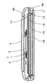
本実施の形態1にかかる携帯端末装置のサブディスプレイホルダ4を図3のC−Cで切断したときの断面図を図4に示す。図4において、4aは枠であり、4bは支え部である。サブディスプレイホルダ4の下面は4gのように外側に向かってテーパー状に薄くなっている。テーパーの傾斜については、図4で示す「H1」の寸法を1としたときに「H2」の寸法を0.2程度という浅いテーパー形状にしている。なお、断面図の各角については図4では尖っているように示しているが、実際には、各角にアールをとって、各角の面を曲面に仕上げている。
FIG. 4 shows a cross-sectional view when the
図5は、本実施の形態1のサブディスプレイホルダ4を裏返して見たときの斜視図である。サブディスプレイホルダ4の下面の周囲をぐるりとテーパー状にしてテーパー面4gを形成している。固定部4fの周囲についてもテーパー面を形成している。なお、図5の小さい矢印は、テーパー面4gの傾斜の向きを示している。
FIG. 5 is a perspective view of the
図6は、本実施の形態1のサブディスプレイホルダ4を裏返して見た斜視図の部分拡大図である。サブディスプレイホルダ4の下面のコーナー部分にRをつけたR形状にしていることを示している。
FIG. 6 is a partially enlarged view of a perspective view of the
図7に、折り畳み式携帯電話機100の第二筐体2の断面図を再び示し、矢印Dの方向にサブディスプレイパネル6を押し始めたときの状態を示している。矢印D方向に加えられた押圧力は、サブディスプレイパネル6からサブディスプレイ用筐体2bに伝わり、サブディスプレイ用筐体2bからサブディスプレイホルダ4に伝わる。押圧力は、矢印Eに示すようにサブディスプレイホルダ4からその下のプリント基板12に伝わるのであるが、サブディスプレイホルダ4の下面が外方向にテーパー状に薄くなっているため、押圧力が加わるとサブディスプレイホルダ4の下面のテーパー面4gがプリント基板に接するようになる。テーパー面4gとプリント基板が面で接触することになるため、プリント基板12に加わる力は角(エッジ)に集中せず、分散される。テーパー面4gとプリント基板12との圧力は小さい値になってしまう。プリント基板12よりメインディスプレイ側にあるバックライト反射板11、導光板14、メインディスプレイ15に集中した押圧力はかからない。このことにより、折り畳んだ状態の携帯端末装置の筐体が押圧されたとき、サブディスプレイとメインディスプレイが近接していたとしても、メインディスプレイが変形したり、破壊したりすることが防止される。
FIG. 7 shows a sectional view of the
(実施の形態2)
次に、本発明の実施の形態2について説明する。本発明の実施の形態2では、サブディスプレイホルダに枠をまたぐ背面板を設けた点に特徴がある。背面板を設けたことによりサブディスプレイホルダの剛性を高め、サブディスプレイホルダに押圧力が加わったときの変形量を小さくしている。
(Embodiment 2)
Next, a second embodiment of the present invention will be described. The second embodiment of the present invention is characterized in that a back plate that straddles the frame is provided on the sub display holder. By providing the back plate, the rigidity of the sub display holder is increased, and the deformation amount when a pressing force is applied to the sub display holder is reduced.
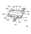
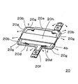
図8に、本実施の形態2のサブディスプレイホルダ20とサブディスプレイ5を斜め上方向から見た分解斜視図を示す。図8において、サブディスプレイ5はサブディスプレイホルダ20対して、矢印B方向に合体されることは図3と同じである。サブディスプレイホルダ20の基本的な形状も図3と同じである。図8のサブディスプレイホルダ20には、サブディスプレイホルダの剛性を高め、枠20aの変形を防止するための背面板20hを設けている。サブディスプレイホルダ20の他の部分は、特に説明したところ以外は基本的に実施の形態1(図3)のサブディスプレイホルダ4と同じである。
FIG. 8 shows an exploded perspective view of the
図9は、本実施の形態2のサブディスプレイホルダ20を裏返して見た斜視図である。サブディスプレイホルダ20の枠20aに背面板20hを設けていることを示している。背面板20hがあると断面係数は大きくなり枠20aは変形しにくくなる。
FIG. 9 is a perspective view of the
図10に、本発明の実施の形態2の折り畳み式携帯電話機の第二筐体2の断面図を示す。図10では、プリント基板が22aと22bの二つに分かれていて、その間の空間にサブディスプレイホルダ20の背面板20hを納めていることを示す。
FIG. 10 shows a cross-sectional view of the
図11に、本発明の実施の形態2の折り畳み式携帯電話機の第二筐体2の断面図を再び示し、矢印Dの方向にサブディスプレイパネル6を押し始めたときの状態を示している。矢印D方向に加えられた押圧力は、サブディスプレイパネル6からサブディスプレイ用筐体2bに伝わり、サブディスプレイ用筐体2bからサブディスプレイホルダ20に伝わる。しかし、実施の形態2のサブディスプレイホルダ20は背面板20hにより剛性が増しているので変形しにくく、サブディスプレイホルダ20が平面を保ったままプリント基板22bに力を伝えることとなる。そのため、折り畳んだ状態の携帯端末装置の筐体が押圧されたとき、サブディスプレイとメインディスプレイが近接していたとしても、メインディスプレイが変形したり、破壊したりすることが更に防止される。
FIG. 11 is a cross-sectional view of the
なお、押圧力が衝撃的に加わった場合にディスプレイホルダ20は変形するが、ディスプレイホルダ20が変形したとしてもディスプレイホルダ20の下面のテーパー面20gがプリント基板22bに接するので、プリント基板12よりメインディスプレイ側にあるバックライト反射板11、導光板14、メインディスプレイ15に集中した押圧力はかからない。そのため、押圧力が衝撃的に加わった場合であっても、メインディスプレイが変形したり破壊したりすることが防止される。
Although the
なお、前述の実施の形態1及び実施の形態2では、サブディスプレイ及びメインディスプレイとして、液晶表示装置を例にあげて説明したが、サブディスプレイ及びメインディスプレイのいずれかひとつ又は両者が有機EL素子を用いた表示装置等の他の表示手段であっても同様である。 In the first embodiment and the second embodiment described above, the liquid crystal display device has been described as an example of the sub display and the main display. However, one or both of the sub display and the main display include organic EL elements. The same applies to other display means such as the display device used.
また、前述の実施の形態1及び実施の形態2では、サブディスプレイ用ホルダの底部を浅いテーパ形状にする例を説明したが、これに代えて、サブディスプレイ用ホルダの底部をR形状にすることもできる。このことにより、携帯端末装置が押圧されたときに、サブディスプレイ用ホルダの底部から伝わるメインディスプレイへの押圧力を分散させ、メインディスプレイを変形や破壊から防ぐこともできる。 In the first embodiment and the second embodiment described above, the example in which the bottom portion of the sub-display holder is formed in a shallow taper shape has been described. Instead, the bottom portion of the sub-display holder is formed in an R shape. You can also. Thus, when the mobile terminal device is pressed, the pressing force applied to the main display transmitted from the bottom of the sub-display holder can be dispersed to prevent the main display from being deformed or broken.
また、前述の実施の形態1及び実施の形態2では、サブディスプレイ用ホルダの底部の角部をR形状にする例を説明したが、これに代えて、または、これに加えて、サブディスプレイ用ホルダの底部の角部の下の構造物に穴をあけることもできる。このことにより、携帯端末装置が押圧されたときに、サブディスプレイ用ホルダの底部の角部から伝わるメインディスプレイへの押圧力を分散させ、メインディスプレイを変形や破壊を防ぐこともできる。 In the first and second embodiments described above, an example in which the corner of the bottom portion of the sub-display holder has an R shape has been described, but instead of or in addition to this, for the sub-display It is also possible to drill holes in the structure below the corners of the bottom of the holder. Thereby, when the portable terminal device is pressed, the pressing force applied to the main display transmitted from the corner portion of the bottom of the sub-display holder can be dispersed to prevent the main display from being deformed or broken.
本発明は、携帯端末装置の筐体が押圧されたとき、サブディスプレイとメインディスプレイが近接していたとしても、メインディスプレイが変形したり、破壊したりすることを防止することができ、筐体の一方の面にメインディスプレイを配置し、他方の面にサブディスプレイを配置した携帯電話機、PDA(Personal Digital Assistants、携帯情報端末)、ノートパソコン、携帯型ゲーム機その他の携帯端末装置に適用することができる。 The present invention can prevent the main display from being deformed or destroyed even when the sub display and the main display are close to each other when the casing of the portable terminal device is pressed. To a mobile phone, PDA (Personal Digital Assistant), notebook computer, portable game machine or other portable terminal device in which a main display is arranged on one side and a sub-display is arranged on the other side Can do.
1 メインディスプレイ用筐体
2 サブディスプレイ用筐体
3 ヒンジ
4 サブディスプレイホルダ
4g テーパー面
5 サブディスプレイ
6 サブディスプレイパネル
7 スポンジ
11 反射板
12 プリント基板
13 メインデイスプレイホルダ
14 導光板
15 メインディスプレイ
16 メインディスプレイパネル
DESCRIPTION OF SYMBOLS 1
Claims (3)
サブディスプレイ用ホルダの底部を浅いテーパ形状にしたことを特徴とする携帯端末装置。 In the mobile terminal device in which the main display is arranged on one side of the housing and the sub display is arranged on the other side,
A portable terminal device characterized in that the bottom of the sub-display holder has a shallow taper shape.
サブディスプレイ用ホルダの底部の角部をR形状にしたことを特徴とする携帯端末装置。 In the mobile terminal device in which the main display is arranged on one side of the housing and the sub display is arranged on the other side,
A portable terminal device characterized in that the corner of the bottom of the sub-display holder has an R shape.
The portable terminal device according to claim 1, wherein the sub-display holder includes a frame and a back plate straddling the frame.
Priority Applications (4)
| Application Number | Priority Date | Filing Date | Title |
|---|---|---|---|
| JP2007259609A JP2009089304A (en) | 2007-10-03 | 2007-10-03 | Portable terminal device |
| CN200880110071A CN101816027A (en) | 2007-10-03 | 2008-08-06 | Portable terminal device |
| EP08836739A EP2196984A1 (en) | 2007-10-03 | 2008-08-06 | Portable terminal device |
| PCT/JP2008/002136 WO2009044499A1 (en) | 2007-10-03 | 2008-08-06 | Portable terminal device |
Applications Claiming Priority (1)
| Application Number | Priority Date | Filing Date | Title |
|---|---|---|---|
| JP2007259609A JP2009089304A (en) | 2007-10-03 | 2007-10-03 | Portable terminal device |
Publications (1)
| Publication Number | Publication Date |
|---|---|
| JP2009089304A true JP2009089304A (en) | 2009-04-23 |
Family
ID=40525932
Family Applications (1)
| Application Number | Title | Priority Date | Filing Date |
|---|---|---|---|
| JP2007259609A Pending JP2009089304A (en) | 2007-10-03 | 2007-10-03 | Portable terminal device |
Country Status (4)
| Country | Link |
|---|---|
| EP (1) | EP2196984A1 (en) |
| JP (1) | JP2009089304A (en) |
| CN (1) | CN101816027A (en) |
| WO (1) | WO2009044499A1 (en) |
Families Citing this family (4)
| Publication number | Priority date | Publication date | Assignee | Title |
|---|---|---|---|---|
| KR101515629B1 (en) | 2012-01-07 | 2015-04-27 | 삼성전자주식회사 | Method and apparatus for providing event of portable device having flexible display unit |
| KR102049856B1 (en) * | 2013-02-21 | 2019-11-28 | 엘지전자 주식회사 | Display device |
| KR101801554B1 (en) | 2013-07-11 | 2017-11-27 | 삼성전자주식회사 | User terminal device for displaying contents and methods thereof |
| FR3115611B1 (en) * | 2020-10-26 | 2023-03-31 | Valeo Comfort & Driving Assistance | Assembly device suitable for assembling a screen with a partially transparent element and head-up display comprising such a device |
Citations (2)
| Publication number | Priority date | Publication date | Assignee | Title |
|---|---|---|---|---|
| JP2004112659A (en) * | 2002-09-20 | 2004-04-08 | Nec Access Technica Ltd | Foldable cellular phone |
| JP2006303687A (en) * | 2005-04-18 | 2006-11-02 | Fujitsu Ltd | Display module and portable terminal unit |
Family Cites Families (8)
| Publication number | Priority date | Publication date | Assignee | Title |
|---|---|---|---|---|
| JP2004151551A (en) * | 2002-10-31 | 2004-05-27 | Seiko Epson Corp | Electro-optical panel, holding structure of electro-optical panel, electro-optical device, method of manufacturing electro-optical panel and method of manufacturing electro-optical device |
| JP2004271839A (en) * | 2003-03-07 | 2004-09-30 | Toshiba Matsushita Display Technology Co Ltd | Liquid crystal display module for double-face display |
| JP2005189512A (en) * | 2003-12-25 | 2005-07-14 | Nec Corp | Impact absorption structure of rear lcd in electronic device and electronic device provided with the structure |
| JP4689304B2 (en) * | 2004-06-29 | 2011-05-25 | パナソニック株式会社 | Liquid crystal display |
| KR100631193B1 (en) * | 2004-10-27 | 2006-10-04 | 삼성전자주식회사 | Display device and mobile phone having the same |
| KR100677747B1 (en) | 2005-02-18 | 2007-02-02 | 삼성전자주식회사 | Dual type lcd module for mobile phone |
| JP2007033658A (en) * | 2005-07-25 | 2007-02-08 | Fujitsu Ltd | Information processor |
| JP4856999B2 (en) | 2006-03-24 | 2012-01-18 | 日立アプライアンス株式会社 | motor |
-
2007
- 2007-10-03 JP JP2007259609A patent/JP2009089304A/en active Pending
-
2008
- 2008-08-06 EP EP08836739A patent/EP2196984A1/en not_active Withdrawn
- 2008-08-06 WO PCT/JP2008/002136 patent/WO2009044499A1/en active Application Filing
- 2008-08-06 CN CN200880110071A patent/CN101816027A/en active Pending
Patent Citations (2)
| Publication number | Priority date | Publication date | Assignee | Title |
|---|---|---|---|---|
| JP2004112659A (en) * | 2002-09-20 | 2004-04-08 | Nec Access Technica Ltd | Foldable cellular phone |
| JP2006303687A (en) * | 2005-04-18 | 2006-11-02 | Fujitsu Ltd | Display module and portable terminal unit |
Also Published As
| Publication number | Publication date |
|---|---|
| CN101816027A (en) | 2010-08-25 |
| EP2196984A1 (en) | 2010-06-16 |
| WO2009044499A1 (en) | 2009-04-09 |
Similar Documents
| Publication | Publication Date | Title |
|---|---|---|
| JP4764062B2 (en) | Electronics | |
| JP2004251938A (en) | Protective structure for lcd panel | |
| JP4460500B2 (en) | Mobile terminal device | |
| JP2009081651A (en) | Electronic apparatus | |
| JP2009089304A (en) | Portable terminal device | |
| JP4802809B2 (en) | Double-sided LCD module | |
| US8811036B2 (en) | Electronic device and frame member | |
| JP4405532B2 (en) | Foldable mobile phone | |
| JP2005189512A (en) | Impact absorption structure of rear lcd in electronic device and electronic device provided with the structure | |
| KR20070054177A (en) | Portable electronic apparatus | |
| JP2006237949A (en) | Electronic equipment | |
| JP2007033658A (en) | Information processor | |
| JP2006126832A (en) | Display device and mobile phone provided with the same | |
| JP2007171738A (en) | Liquid crystal module | |
| JP2005151376A (en) | Portable terminal device | |
| JP2004172454A (en) | Portable electronic apparatus | |
| JP2006119299A (en) | Portable device | |
| JP4697117B2 (en) | LCD protective structure for portable communication devices | |
| JP4182067B2 (en) | Foldable electronic device and case abutting structure of foldable electronic device | |
| JP5451061B2 (en) | Display device protection structure | |
| JP2008263347A (en) | Electronic apparatus | |
| JP2008160534A (en) | Portable radio apparatus | |
| JP4994114B2 (en) | Mobile terminal device | |
| JP4930841B2 (en) | Electronics | |
| JP2010166434A (en) | Mobile device |
Legal Events
| Date | Code | Title | Description |
|---|---|---|---|
| RD01 | Notification of change of attorney |
Free format text: JAPANESE INTERMEDIATE CODE: A7421 Effective date: 20091127 |
|
| A131 | Notification of reasons for refusal |
Free format text: JAPANESE INTERMEDIATE CODE: A131 Effective date: 20100316 |
|
| A02 | Decision of refusal |
Free format text: JAPANESE INTERMEDIATE CODE: A02 Effective date: 20100706 |