JP2009083317A - Image forming method and image forming device - Google Patents
Image forming method and image forming device Download PDFInfo
- Publication number
- JP2009083317A JP2009083317A JP2007256724A JP2007256724A JP2009083317A JP 2009083317 A JP2009083317 A JP 2009083317A JP 2007256724 A JP2007256724 A JP 2007256724A JP 2007256724 A JP2007256724 A JP 2007256724A JP 2009083317 A JP2009083317 A JP 2009083317A
- Authority
- JP
- Japan
- Prior art keywords
- intermediate transfer
- ink
- image
- treatment agent
- solid
- Prior art date
- Legal status (The legal status is an assumption and is not a legal conclusion. Google has not performed a legal analysis and makes no representation as to the accuracy of the status listed.)
- Pending
Links
Images


Classifications
-
- B—PERFORMING OPERATIONS; TRANSPORTING
- B41—PRINTING; LINING MACHINES; TYPEWRITERS; STAMPS
- B41M—PRINTING, DUPLICATING, MARKING, OR COPYING PROCESSES; COLOUR PRINTING
- B41M5/00—Duplicating or marking methods; Sheet materials for use therein
- B41M5/025—Duplicating or marking methods; Sheet materials for use therein by transferring ink from the master sheet
- B41M5/0256—Duplicating or marking methods; Sheet materials for use therein by transferring ink from the master sheet the transferable ink pattern being obtained by means of a computer driven printer, e.g. an ink jet or laser printer, or by electrographic means
-
- B—PERFORMING OPERATIONS; TRANSPORTING
- B41—PRINTING; LINING MACHINES; TYPEWRITERS; STAMPS
- B41M—PRINTING, DUPLICATING, MARKING, OR COPYING PROCESSES; COLOUR PRINTING
- B41M5/00—Duplicating or marking methods; Sheet materials for use therein
- B41M5/025—Duplicating or marking methods; Sheet materials for use therein by transferring ink from the master sheet
- B41M5/03—Duplicating or marking methods; Sheet materials for use therein by transferring ink from the master sheet by pressure
Landscapes
- Engineering & Computer Science (AREA)
- General Engineering & Computer Science (AREA)
- Ink Jet (AREA)
- Ink Jet Recording Methods And Recording Media Thereof (AREA)
Abstract
Description
本発明は画像形成方法及び画像形成装置に係り、特に、中間転写体上に形成したインク画像(1次画像)を記録媒体に転写する画像形成方法及び画像形成装置に関する。 The present invention relates to an image forming method and an image forming apparatus, and more particularly to an image forming method and an image forming apparatus for transferring an ink image (primary image) formed on an intermediate transfer member to a recording medium.
従来より、インクジェット方式の記録ヘッド(インクジェットヘッド)に形成される複数のノズルからインク液滴を吐出することによって中間転写体上にインク画像(1次画像)を形成し、中間転写体上に形成されたインク画像を記録媒体に転写する方式(以下、「転写記録方式」という。)のインクジェット記録装置が知られている。 Conventionally, an ink image (primary image) is formed on an intermediate transfer body by ejecting ink droplets from a plurality of nozzles formed on an inkjet recording head (inkjet head), and then formed on the intermediate transfer body. There is known an ink jet recording apparatus of a system (hereinafter referred to as “transfer recording system”) for transferring the ink image to a recording medium.
近年、転写記録方式に対する高画質化や高速記録化の要求が高まっており、中間転写体から記録媒体に対する転写性を向上させることが技術的課題の1つに挙げられている。 In recent years, there has been an increasing demand for higher image quality and higher speed recording for transfer recording systems, and one of the technical problems is to improve transferability from an intermediate transfer body to a recording medium.
特許文献1には、ワックス又は滑剤からなる滑性塗工層を、離型性能をもつ中間転写体表面層(離型層)上に形成し、転写ローラ温度をワックス又は滑剤の融点以上に設定し、転写時に転写ローラと接することにより滑性塗工層が部分的に溶融し、中間転写体上に形成された画像の離型性を更に向上させる技術が開示されている。
しかしながら、特許文献1に記載の発明は、ワックス又は滑剤からなる滑性塗工層を中間転写体表面上に形成するには多量のワックスまたは滑剤を付与しなければならず、更に転写するメディア全域に画像部、非画像部を問わず、溶融したワックス又は滑剤の平滑な層が付着することになる。その結果、転写された記録媒体上の非画像部に必要以上に光沢性を発現させることになり、得られる画像の質感が損なわれる問題がある。
However, in the invention described in
また、表面粗さの低い滑性の層では、ワックス又は滑剤からなる滑性塗工層上に形成された画像中の色材が、液のぬれ拡がり或いは乾燥によるヒケで移動してしまい、転写して得られる画像に画像乱れを引き起こす。 In addition, in a slippery layer having a low surface roughness, the color material in the image formed on the slippery coating layer made of wax or lubricant moves due to spreading of the liquid or sink marks due to drying, and transfer. This causes image disturbance in the image obtained.
更には、滑性塗工層は一旦溶融させ冷却固化した固化膜の形態で中間転写体表面上に存在するために、転写時においては、離型性よりも密着性がまさり、却って転写率を低下させてしまうおそれもある。特に高速で転写が行われる場合にはこの傾向が強くなる。 Furthermore, since the slippery coating layer exists on the surface of the intermediate transfer member in the form of a solidified film that has been once melted and cooled and solidified, adhesion is superior to releasability during transfer, and on the contrary, the transfer rate is increased. There is also a risk of lowering. This tendency is particularly strong when transfer is performed at high speed.
本発明はこのような事情に鑑みてなされたもので、転写記録方式において、色材移動による画像乱れや記録媒体上の非画像部での光沢性の発現を防止するとともに、高速での転写性を向上させた画像形成方法及び画像形成装置を提供することを目的とする。 The present invention has been made in view of such circumstances, and in the transfer recording method, image disturbance due to color material movement and expression of glossiness in a non-image portion on a recording medium are prevented, and high-speed transferability is achieved. An object of the present invention is to provide an image forming method and an image forming apparatus with improved image quality.
前記目的を達成するために、本発明に係る画像形成方法は、中間転写体上に少なくとも1種類の固体粒子を含む処理剤からなる固体状又は半固溶状の処理剤層を形成する工程と、画像データに応じて、前記中間転写体上に形成された前記処理剤層の表面にインクを液滴化して打滴する工程と、前記中間転写体の表面温度を前記固体粒子の融点未満にした状態で前記中間転写体から記録媒体に対して画像転写を行う工程と、を含み、前記中間転写体上に形成される前記処理剤層の表面粗さ(Ra)は前記インクに含有される色材の粒子径よりも大きいことを特徴とする。 In order to achieve the above object, an image forming method according to the present invention includes a step of forming a solid or semi-solid solution treatment agent layer comprising a treatment agent containing at least one kind of solid particles on an intermediate transfer member; In accordance with image data, a step of forming ink droplets on the surface of the processing agent layer formed on the intermediate transfer body and ejecting the ink, and the surface temperature of the intermediate transfer body is set to be lower than the melting point of the solid particles. Transferring the image from the intermediate transfer member to the recording medium in a state where the surface roughness (Ra) of the treatment agent layer formed on the intermediate transfer member is a color contained in the ink It is characterized by being larger than the particle diameter of the material.
本発明によれば、中間転写体上の処理剤層の表面に形成された凹部に色材が固定されるので、色材移動による画像乱れを防止することができる。また、固体粒子は溶融することなく粒子形状を保った状態で転写が行われるため、高速での転写性が向上するとともに、記録媒体上の非画像部での光沢性の発現を防止することができる。 According to the present invention, since the color material is fixed to the concave portion formed on the surface of the processing agent layer on the intermediate transfer body, it is possible to prevent image disturbance due to color material movement. In addition, since the solid particles are transferred in a state where the particle shape is maintained without melting, transferability at high speed is improved, and glossiness can be prevented in a non-image portion on the recording medium. it can.
本明細書において、「固体状又は半固溶状の処理剤(処理剤層)」とは、処理剤(処理剤層)の含水率が0〜70%の範囲であるものを指す。なお、「含水率」は、処理剤の単位面積あたりの重量X1[g/m2]に対する処理剤中に含まれる水の単位面積あたりの重量X2[g/m2]の比(即ち、X2/X1)と定義する。 In the present specification, the “solid or semi-solid treatment agent (treatment agent layer)” refers to a treatment agent (treatment agent layer) having a moisture content in the range of 0 to 70%. The “moisture content” is the ratio of the weight X 2 [g / m 2 ] per unit area of water contained in the treatment agent to the weight X 1 [g / m 2 ] per unit area of the treatment agent (that is, , X 2 / X 1 ).
また、「処理剤」は、固体状又は半固溶状のものだけでなく、それ以外の液体状のものも含む広い概念で用いるものとし、特に、含水率を70%として液体状にした処理剤を「処理液」と称する。 In addition, the “treatment agent” is used in a broad concept including not only solid or semi-solid solution but also other liquid, and in particular, a treatment agent in a liquid state with a moisture content of 70%. Is referred to as “treatment liquid”.
請求項2に記載の発明は、請求項1に記載の画像形成方法の一態様に係り、前記固体状又は半固溶状の処理剤層を形成する工程は、前記中間転写体上に前記処理剤を付与する工程と、前記中間転写体上に付与された前記処理剤を乾燥させて、前記中間転写体上に前記処理剤からなる固体状又は半固溶状の処理剤層を形成する工程と、を含むことを特徴とする。 According to a second aspect of the present invention, there is provided the image forming method according to the first aspect, wherein the step of forming the solid or semi-solid treatment agent layer includes the treatment agent on the intermediate transfer member. And a step of drying the treatment agent applied on the intermediate transfer member to form a solid or semi-solid treatment agent layer comprising the treatment agent on the intermediate transfer member; It is characterized by including.
中間転写体上に処理剤を付与する手段としては、塗布ローラなどの塗布手段やインクジェットヘッドなどを適用することができる。塗布手段を用いる場合には、均一な厚みをもつ薄層(処理剤層)を形成することができる。また、インクジェットヘッドを用いる場合には、記録画像(画像データ)に応じて処理剤を選択的に付与することが可能となり、処理剤の削減や乾燥エネルギーの削減が可能となる。 As means for applying the treatment agent onto the intermediate transfer member, application means such as an application roller, an ink jet head, or the like can be applied. When using a coating means, a thin layer (treatment agent layer) having a uniform thickness can be formed. Further, when an ink jet head is used, it is possible to selectively apply a processing agent according to a recorded image (image data), and it is possible to reduce the processing agent and drying energy.
請求項3に記載の発明は、請求項1又は請求項2に記載の画像形成方法の一態様に係り、 前記処理剤は、前記インクの色材を凝集させる成分を含むことを特徴とする。 A third aspect of the present invention relates to an aspect of the image forming method according to the first or second aspect, wherein the processing agent includes a component that aggregates the color material of the ink.
本発明において、インクの色材を凝集させる成分(色材凝集成分)を含む処理剤が用いられることが好ましい。このような処理剤からなる固体状又は半固溶状の処理剤層の表面にインク液滴が着弾すると瞬時に凝集反応が始まり、色材粒子の浮遊を防止でき、色材移動の防止により効果がある。また、インク画像を構成する色材の凝集力を向上させることができ、転写時のオフセット(なき別れ)を妨げ、転写性向上により効果がある。 In the present invention, it is preferable to use a treatment agent containing a component that aggregates the color material of the ink (color material aggregation component). When ink droplets land on the surface of a solid or semi-solid treatment agent layer made of such a treatment agent, an agglomeration reaction starts instantly, preventing the color material particles from floating, and preventing the movement of the color material. is there. In addition, the cohesive force of the color material constituting the ink image can be improved, the offset (separation) at the time of transfer is prevented, and the transfer property is more effective.
請求項4に記載の発明は、請求項1乃至請求項3のいずれか1項に記載の画像形成方法の一態様に係り、前記インクはポリマー微粒子を含むことを特徴とする。 According to a fourth aspect of the present invention, there is provided an image forming method according to any one of the first to third aspects, wherein the ink includes polymer fine particles.
本発明において、ポリマー微粒子を含むインクが用いられることが好ましい。インクの凝集力向上によって画像乱れを抑制することができるとともに、転写性を向上させることができる。 In the present invention, it is preferable to use ink containing polymer fine particles. Image disturbance can be suppressed by improving the cohesive strength of the ink, and transferability can be improved.
請求項5に記載の発明は、請求項4に記載の画像形成方法の一態様に係り、前記中間転写体の表面温度は、前記ポリマー微粒子のガラス転移温度よりも高く、且つ、前記固体粒子の融点よりも低いことを特徴とする。
The invention according to
請求項5に記載の態様によれば、ポリマー微粒子の融着によって転写性を向上させることができる。
According to the aspect of
請求項6に記載の発明は、請求項1乃至請求項5のいずれか1項に記載の画像形成方法の一態様に係り、前記処理剤は、第1の固体粒子を含むとともに、前記第1の固体粒子に比べて融点が低い第2の固体粒子を含み、前記中間転写体の表面温度は、前記第1の固体粒子の融点よりも低く、且つ、前記第2の固体粒子の融点よりも高いことを特徴とする。 A sixth aspect of the present invention relates to an aspect of the image forming method according to any one of the first to fifth aspects, wherein the processing agent includes first solid particles and the first solid particles. Second solid particles having a melting point lower than that of the solid particles, the surface temperature of the intermediate transfer member is lower than the melting point of the first solid particles, and is lower than the melting point of the second solid particles. It is characterized by being expensive.
請求項6に記載の態様によれば、第1の固体粒子を溶融させることなく、第2の固体粒子を溶融させることによって、固体状又は半固溶状の処理剤層の固定性及び強度を向上させることができ、色材移動による画像乱れを確実に防止することができる。また、転写時における処理剤層の分断による転写性の低下を防ぐことができる。
According to the aspect of
第2の固体粒子の粒子径は、第1の固体粒子の粒子径よりも小さいことが好ましく、乾燥時に毛管力などの作用により大粒子(第1の固体粒子)の周囲に小粒子(第2の固体粒子)が密集しやすくなり、第2の固体粒子の溶融によって処理剤層の固定性及び強度を増すことができる。 The particle size of the second solid particles is preferably smaller than the particle size of the first solid particles, and small particles (second solid particles) around the large particles (first solid particles) due to an action such as capillary force during drying. Solid particles) can be easily concentrated, and the fixation and strength of the treatment agent layer can be increased by melting the second solid particles.
また、前記目的を達成するために装置発明を提供する。即ち、請求項7に記載の発明は、中間転写体上に少なくとも1種類の固体粒子を含む処理剤からなる固体状又は半固溶状の処理剤層を形成する処理剤層形成手段と、画像データに応じて、前記中間転写体上に形成された前記処理剤層の表面にインクを液滴化して打滴するインク打滴手段と、前記中間転写体の表面温度を前記固体粒子の融点未満にした状態で前記中間転写体から記録媒体に対して画像転写を行う転写手段と、を備え、前記中間転写体上に形成される前記処理剤層の表面粗さ(Ra)は前記インクに含有される色材の粒子径よりも大きいことを特徴とする。
In order to achieve the above object, an apparatus invention is provided. That is, the invention according to
請求項8に記載の発明は、請求項7に記載の画像形成装置の一態様に係り、前記処理剤層形成手段は、前記中間転写体上に前記処理剤を付与する手段、及び前記中間転写体上に付与された前記処理剤を乾燥させて、前記中間転写体上に前記処理剤からなる固体状又は半固溶状の処理剤層を形成する手段を含んで構成されることを特徴とする。 The invention according to an eighth aspect relates to an aspect of the image forming apparatus according to the seventh aspect, wherein the processing agent layer forming unit applies the processing agent onto the intermediate transfer member, and the intermediate transfer. It comprises a means for drying the treatment agent applied on the body to form a solid or semi-solid treatment agent layer comprising the treatment agent on the intermediate transfer member. .
本発明によれば、中間転写体上の処理剤層の表面に形成された凹部に色材が固定されるので、色材移動による画像乱れを防止することができる。また、固体粒子は溶融することなく粒子形状を保った状態で転写が行われるため、高速での転写性が向上するとともに、記録媒体上の非画像部での光沢性の発現を防止することができる。 According to the present invention, since the color material is fixed to the concave portion formed on the surface of the processing agent layer on the intermediate transfer body, it is possible to prevent image disturbance due to color material movement. In addition, since the solid particles are transferred in a state where the particle shape is maintained without melting, transferability at high speed is improved, and glossiness can be prevented in a non-image portion on the recording medium. it can.
以下、添付図面に従って本発明の好ましい実施の形態について詳説する。 Hereinafter, preferred embodiments of the present invention will be described in detail with reference to the accompanying drawings.
〔インクジェット記録装置〕
図1は、本発明の実施形態に係るインクジェット記録装置の概略構成図である。図1に示すインクジェット記録装置10は、中間転写体12上に処理剤(処理液)を付与する処理剤付与部16と、中間転写体12上に付与された処理剤を乾燥させて、中間転写体12上に固体状又は半固溶状の処理剤層を形成する乾燥部18と、シアン(C)、マゼンダ(M)、イエロー(Y)、黒(K)の各色インクに対応したインクジェットヘッド(以下、単に「ヘッド」という。)20C、20M、20Y、20Kを有する印字部(インク打滴部)20と、中間転写体12上に形成されたインク画像(1次画像)を記録媒体14に転写する転写部22とから主に構成される。
[Inkjet recording device]
FIG. 1 is a schematic configuration diagram of an ink jet recording apparatus according to an embodiment of the present invention. The ink
本発明で用いられるインク及び処理剤(処理液)については後で詳説するが、本発明では、溶媒不溶性材料として、色材(着色剤)である顔料やポリマー微粒子などを含有する水性顔料インクが好適に用いられる。 The ink and the treatment agent (treatment liquid) used in the present invention will be described in detail later. In the present invention, an aqueous pigment ink containing a pigment that is a colorant (colorant), polymer fine particles, or the like is used as a solvent-insoluble material. Preferably used.
また、本発明では、少なくとも1種類の固体粒子(第1の固体粒子)を含む処理剤が用いられる。固体粒子としては、ワックス素材などの結晶性ポリマーが望ましく、例えば、ポリエチレンワックス、パラフィンワックスなどが好ましい。処理剤に含まれる固体粒子の融点は50〜140℃の範囲のものが好適に用いられる。 In the present invention, a treating agent containing at least one kind of solid particles (first solid particles) is used. As the solid particles, a crystalline polymer such as a wax material is desirable. For example, polyethylene wax, paraffin wax and the like are preferable. The solid particles contained in the treating agent preferably have a melting point in the range of 50 to 140 ° C.
第1の固体粒子だけでなく、第1の固体粒子に比べて融点の低い第2の固体粒子を含む処理剤が用いられることが好ましい。また、第2の固体粒子の粒子径は第1の固体粒子の粒子径よりも小さいことが好ましい。中間転写体12上に形成される固体状又は半固溶状の処理剤層の固定性及び強度を向上させ、画像乱れを確実に防ぎ、転写時における処理剤層の分断による転写性の低下を防ぐことができる。
It is preferable to use a treatment agent containing not only the first solid particles but also the second solid particles having a lower melting point than the first solid particles. The particle size of the second solid particles is preferably smaller than the particle size of the first solid particles. Improves the fixability and strength of the solid or semi-solid treatment agent layer formed on the
また、インクの色材を凝集させる成分(色材凝集成分)を含む処理剤が用いられることが好ましい。このような処理剤からなる固体状又は半固溶状の処理剤層の表面にインク液滴が着弾すると瞬時に凝集反応が始まり、色材粒子の浮遊を防止でき、色材移動の防止により効果がある。また、インク画像を構成する色材の凝集力を向上させることができ、転写時のオフセット(なき別れ)を妨げ、転写性向上により効果がある。 Further, it is preferable to use a treatment agent containing a component that aggregates the color material of the ink (color material aggregation component). When ink droplets land on the surface of a solid or semi-solid treatment agent layer made of such a treatment agent, an agglomeration reaction starts instantly, preventing the color material particles from floating, and preventing the movement of the color material. is there. In addition, the cohesive force of the color material constituting the ink image can be improved, the offset (separation) at the time of transfer is prevented, and the transfer property is more effective.
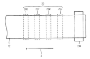
図1に示す中間転写体12には無端状ベルトが適用され、中間転写体(無端状ベルト)12は複数の張架ローラ(図1には7つの張架ローラ24A〜24Gを図示)に巻きかけられた構造を有し、張架ローラ24A〜24Gの少なくとも1つにモータ(図1中不図示、図6に符号88で図示)の動力が伝達されることにより、中間転写体12は、図1において反時計回り方向(図1中、矢印Aで示す方向;以下、「中間転写体搬送方向」という。)に駆動される。
An endless belt is applied to the
中間転写体(無端状ベルト)12は、印字部20と対向する表面(画像形成面)12Aの少なくとも1次画像(インク画像)が形成される画像形成領域(不図示)には、樹脂、金属やゴムなどのインク液滴が浸透しない非浸透性を有している。また、中間転写体12の少なくとも画像形成領域は、所定の平坦性を有する水平面(フラット面)をなすように構成されている。
The intermediate transfer member (endless belt) 12 is formed of resin or metal in an image forming region (not shown) on which at least a primary image (ink image) is formed on a surface (image forming surface) 12A facing the
図1には、中間転写体12の一態様として無端状のベルトを示したが、本発明に適用される中間転写体はドラム形状でもよいし、平板形状でもよい。
In FIG. 1, an endless belt is shown as one embodiment of the
中間転写体12の画像形成面12Aを含む表面層に用いられる好ましい材料としては、例えば、ポリイミド系樹脂、シリコン系樹脂、ポリウレタン系樹脂、ポリエステル系樹脂、ポリスチレン系樹脂、ポリオレフィン系樹脂、ポリブタジエン系樹脂、ポリアミド系樹脂、ポリ塩化ビニル系樹脂、ポリエチレン系樹脂、フッ素系樹脂等の公知の材料が挙げられる。
Preferred materials used for the surface layer including the
また、中間転写体12の表面層の表面張力は10mN/m以上40mN/m以下とする態様が好ましい。中間転写体12の表面層の表面張力を40mN/m以上とすると、1次画像が転写される記録媒体14との表面張力差がなくなり(または、極めて小さくなり)、転写性が悪化する。更に、中間転写体12の表面層の表面張力が10mN/m以下であると、処理剤のぬれ性を考慮した場合に、処理剤の表面張力を中間転写体12の表面層の表面張力よりも小さくする必要があり、処理剤の表面張力を10mN/m以下とすることが困難となり、中間転写体12及び処理剤の設計自由度(選択範囲)が狭くなる。
Further, it is preferable that the surface tension of the surface layer of the
中間転写体搬送方向(図1中、矢印Aで示す方向)最上流側には、中間転写体12上に処理剤(処理液)を付与する処理剤付与部16が配置される。この処理剤付与部16は、塗布ローラ16A、及び処理剤が収容される容器16Bを含んで構成される。塗布ローラ16Aは中間転写体12に対して従動して回転するか、独立して塗布ローラ16Aが駆動し回転制御可能となっている。このように、塗布ローラ16Aが回転することによって、容器16B内の処理剤が中間転写体12の画像形成面12Aに塗布される。
A processing
中間転写体12に対する処理剤の塗布厚は、0.5〜20μmの範囲で設定することが好ましい。塗布厚が0.5μmより小さいと液切れによる膜不均一性が生じやすく品質上の問題となる。また、塗布厚が20μmより大きいと乾燥工程におけるエネルギー付加が大きくなり、また、面状も悪くなる。
The coating thickness of the treatment agent on the
処理剤の塗布厚を制御するには、塗布ローラ16Aと中間転写体12との接触時間を制御する態様が好ましい。塗布ローラ16Aと中間転写体12との接触時間を相対的に長くすると処理剤の塗布厚は相対的に大きくなり、塗布ローラ16Aと中間転写体12との接触時間を相対的に短くすると処理剤の塗布厚は相対的に小さくなる。
In order to control the coating thickness of the treatment agent, a mode in which the contact time between the
塗布ローラ16Aには、多孔質材料や表面に凹凸がある材料が望ましく、例えば、グラビアロール状のもの等を用いることができる。
The
図1には、処理剤の付与形態の一態様として、塗布ローラ16Aを用いる態様を例示したが、処理剤の付与形態は本例に限定されず、ブレードによる塗布、インクジェットヘッドによる打滴など様々な方式を適用することが可能である。特に、インクジェット方式の場合、記録画像(画像データ)に応じて処理剤を正確にパターンニングして付与することができ、後段に配置される乾燥部18の加熱時間の短縮や加熱エネルギーの削減が可能となる。
In FIG. 1, an embodiment using the
処理剤付与部16の中間転写体搬送方向下流側には、中間転写体12上に付与された処理剤(処理液)の乾燥を行う乾燥部18が配置される。この乾燥部18は、ヒータ(図1中不図示、図6に符号89で図示)を含んで構成され、ヒータによる加熱によって中間転写体12上に付与された処理剤を乾燥させて、中間転写体12上に固体状又は半固溶状の処理剤層(以下、単に「処理剤層」という。)を形成する。
A drying
乾燥部18に配置されるヒータの加熱温度は、処理剤の種類、処理剤の付与量(厚み)、環境温度などの諸条件に応じて設定される。特に、本実施形態においては、中間転写体12の表面温度が処理剤に含まれる固体粒子の融点未満となるようにヒータの加熱温度が設定される。これにより、中間転写体12上に付与された処理剤に含まれる固体粒子は溶融することなく、粒子形状を保った状態で処理剤層に存在するので、処理剤層の表面は凹凸状となる。仮に、中間転写体12の表面温度が固体粒子の融点以上となるように加熱を行ってしまうと、固体粒子の粒子形状が崩れてしまい、処理剤層の表面は平坦状となってしまい、色材移動による画像乱れを防止することはできず、また、転写性も悪化してしまう。従って、乾燥部18に配置されるヒータは、処理剤に含まれる固体粒子が溶融することがないように、中間転写体12の表面温度が固体粒子の融点未満となるような加熱温度に設定されることが好ましい。
The heating temperature of the heater disposed in the drying
また、本実施形態においては、中間転写体12上に形成される処理剤層の表面粗さ(Ra)がインクの色材粒子径(顔料粒径)よりも大きくなるように構成される。具体的には、前述した関係を満たすように、処理剤(固体粒子)の種類、処理剤の付与量(厚み)、乾燥条件(加熱条件)などが決められる。後段の印字部20において、処理剤層の表面にインク液滴が打滴されると、処理剤層の表面に形成される凹部に色材粒子(顔料粒子)がトラップされて動くことができなくなるため、色材移動による画像乱れを効果的に防止することができる。
In this embodiment, the surface roughness (Ra) of the treatment agent layer formed on the
処理剤に含まれる固体粒子の添加量(即ち、中間転写体12の表面積に対する固体粒子の被覆率)は、中間転写体12の表面材質の離型性に応じて適切な量に設定されることが望ましい。具体的には、中間転写体12の表面材質の離型性が高い場合には固体粒子の添加量を少なくし、一方、離型性が低い場合には固体粒子の添加量を多くすればよい。後述するように、転写部22では固体粒子の粒子形状が保たれるように転写が行われるため、固体粒子によって中間転写体12に対する処理剤層の離型性が高まり、高速での転写性を向上させることができる。
The addition amount of the solid particles contained in the processing agent (that is, the coverage of the solid particles with respect to the surface area of the intermediate transfer member 12) is set to an appropriate amount according to the releasability of the surface material of the
本実施形態において、第1の固体粒子を含むとともに、第1の固体粒子に比べて融点の低い第2の固体粒子を含む処理剤が用いられることが好ましい。乾燥部18において、第1の固体粒子の融点より低く、且つ、第2の固体粒子の融点より高い加熱温度で前記処理剤を乾燥することにより、第2の固体粒子のみが溶融して第1の固体粒子を固定することができる。これによって、処理剤層自体の固定性及び強度が向上して、画像乱れを確実に防ぎ、転写時における処理剤層の分断による転写性の低下を防止することができる。
In the present embodiment, it is preferable to use a treatment agent that includes the first solid particles and includes the second solid particles having a melting point lower than that of the first solid particles. In the drying
第2の固体粒子の添加量は、第1の固体粒子量に対して、10%以上100%未満とするのが望ましい。10%未満だと効果が不足し、100%以上(等量以上)だと転写性に逆効果である。 The addition amount of the second solid particles is desirably 10% or more and less than 100% with respect to the first solid particle amount. If it is less than 10%, the effect is insufficient, and if it is 100% or more (equal amount or more), the transferability is counterproductive.
また、第2の固体粒子の粒子径は、第1の固体粒子の粒子径よりも小さい方が望ましく、乾燥時に毛管力などの作用により大粒子(第1の固体粒子)の周囲に小粒子(第2の固体粒子)が密集し易くなり、第2の固体粒子の溶融によって固定性及び強度を向上させることができる。 The particle diameter of the second solid particles is preferably smaller than the particle diameter of the first solid particles, and small particles (first solid particles) around the large particles (first solid particles) due to an action such as capillary force during drying. The second solid particles) are easily concentrated, and the fixation and strength can be improved by melting the second solid particles.
本実施形態では、中間転写体12上に固体粒子を含む処理剤(処理液)を付与した後、中間転写体12上の処理剤を加熱により乾燥させて固体状又は半固溶状の処理剤層を形成しているが、中間転写体12上に固体状又は半固溶状の処理剤層を直接形成する態様もある。例えば、流動浸漬法、静電煙霧法、溶射法、静電乾式吹き付け法、散布法などの公知の粉体散布方法を用いて、中間転写体12上に固体状又は半固溶状の処理剤層を直接形成することができる。また、開閉式の蓋の設けられた開口部を有し、且つ、内部に粉体(処理剤)を貯蔵することが可能な容器などを用いて粉体を散布することも可能である。このとき、中間転写体12の通過時のみ蓋を開き、中間転写体12上に粉体を散布し、非使用時には蓋を閉じ、粉体が散布されないように調節する制御手段などを備えて粉体の散布を精密に制御することも可能である。
In this embodiment, after applying a treatment agent (treatment liquid) containing solid particles on the
印字部20は、乾燥部18の中間転写体搬送方向下流側に配置され、中間転写体搬送方向に沿って上流側から順に、シアン(C)、マゼンダ(M)、イエロー(Y)、黒(K)の各色インクに対応したヘッド20C、20M、20Y、20Kが設けられる。印字部20では、画像データに応じて、各ヘッド20C、20M、20Y、20Kからそれぞれ対応する各色のインク液滴が中間転写体12に対して打滴される。各ヘッド20C、20M、20Y、20Kから打滴されたインク液滴は、印字部20より中間転写体搬送方向上流側で中間転写体12上に形成された固体状又は半固溶状の処理剤層の上に着弾する。
The
図2に示すように、各ヘッド20C、20M、20Y、20Kは、それぞれ中間転写体12における画像形成領域の最大幅に対応する長さを有し、そのインク吐出面には画像形成領域の全幅にわたってインク吐出用のノズル(図2中不図示、図3に符号51で図示)が複数配列されたフルライン型のヘッドとなっている。各ヘッド20C、20M、20Y、20Kが中間転写体搬送方向と直交する方向に延在するように固定設置される。
As shown in FIG. 2, each of the
中間転写体12の画像形成領域の全幅をカバーするノズル列を有するフルラインヘッドがインク色毎に設けられる構成によれば、中間転写体12の搬送方向(副走査方向)について、中間転写体12と印字部20を相対的に移動させる動作を1回行うだけで(即ち1回の副走査で)、中間転写体12の画像形成領域に1次画像を記録することができる。これにより、中間転写体搬送方向と直交する方向(主走査方向;図3参照)に往復動作するシリアル(シャトル)型ヘッドが適用される場合に比べて高速印字が可能であり、プリント生産性を向上させることができる。
According to the configuration in which a full line head having a nozzle row covering the entire width of the image forming area of the
本例では、各ヘッド20C、20M、20Y、20Kの各ノズルから吐出されるインク液滴の最小打滴量(吐出体積)は2plであり、最高記録密度(最高ドット密度)は主走査方向(中間転写体搬送方向と直交する方向)及び副走査方向(中間転写体搬送方向)のいずれも1200dpiである。
In this example, the minimum droplet ejection amount (ejection volume) of the ink droplets ejected from the nozzles of the
また、本例では、CMYKの標準色(4色)の構成を例示したが、インク色や色数の組み合わせについては本実施形態に限定されず、必要に応じて淡インク、濃インク、特別色インクを追加してもよい。例えば、ライトシアン、ライトマゼンタなどのライト系インクを吐出するインクヘッドを追加する構成も可能であり、各色ヘッドの配置順序も特に限定はない。 In this example, the configuration of CMYK standard colors (four colors) is illustrated, but the combination of ink colors and the number of colors is not limited to this embodiment, and light ink, dark ink, and special colors are used as necessary. Ink may be added. For example, it is possible to add an ink head that discharges light-colored ink such as light cyan and light magenta, and the arrangement order of the color heads is not particularly limited.
インク貯蔵/装填部26は、各ヘッド20C、20M、20Y、20Kに対応する色インクを貯蔵するインクタンク(図1中不図示、図5に符号60で図示)を含んで構成され、各インクタンクは所要の流路を介してそれぞれ対応するヘッドと連通されている。また、インク貯蔵/装填部26は、インク残量が少なくなるとその旨を報知する報知手段(表示手段、警告音発生手段)を備えるとともに、色間の誤装填を防止するための機構を有している。
The ink storage /
印字部20の中間転写体搬送方向下流側には溶媒除去部28が配置される。この溶媒除去部28は、ローラ状の多孔質体(吸収体)からなる溶媒吸収ローラ28Aを含んで構成され、溶媒吸収ローラ28Aを中間転写体12上の液体溶媒(インクなどの溶媒成分)に接触させて、多孔質体の毛細管力により多孔質体内部に当該液体溶媒を吸収させることによって、中間転写体12上から液体溶媒を除去する。
A
溶媒吸収ローラ28Aは、中間転写体12の移動(搬送)に応じて従動回転させてもよいし、独立して回転させるようにしてもよい。また、中間転写体12の画像形成面12Aから離間可能となるように構成されていることが好ましい。
The solvent
溶媒吸収ローラ28Aの表面(中間転写体12の画像形成面12Aと接触する面)の表面エネルギーは中間転写体12の画像形成面12Aの表面エネルギーよりも小さいことが好ましく、本例では、溶媒吸収ローラ28Aには表面エネルギーが30mN/m以下の部材が適用される。
The surface energy of the surface of the solvent absorbing
上述した表面エネルギーの条件を満たす溶媒吸収ローラ28Aを用いて溶媒除去を行うことにより、溶媒吸収ローラ28Aへの色材付着を防止しつつ、中間転写体12上の液体溶媒を吸収除去することが可能となる。
By removing the solvent using the solvent absorbing
なお、溶媒吸収ローラ28Aに代えて、エアナイフで余剰な溶媒を中間転写体12から取り除く方式や、中間転写体12を加熱(例えば、平板加熱ヒータによる加熱)したり、乾燥風を吹き付けたりして溶媒を蒸発させ除去する方式などを適用してもよい。溶媒除去の方式としては、先に例示した何れの方式でもよいが、加熱によらない方式を用いる方がより好ましい。
Instead of the solvent absorbing
中間転写体12の表面を加熱する方式や、中間転写体12上のインク画像に熱を付与して溶媒を蒸発させる方式では、インク画像の過剰加熱により溶媒を過剰除去してしまい、転写時において好ましいインク画像の粘弾性を維持できず、かえって記録媒体14への転写性が低下することがある。更にまた、過剰加熱により生じた熱が各ヘッド20C、20M、20Y、20Kの吐出性能へ影響を与えることも懸念される。
In the method of heating the surface of the
一方、溶媒吸収ローラ28Aによって中間転写体12の画像形成面12A上の溶媒を吸収除去する態様では、中間転写体12上に多くの溶媒が残存する場合でも、他の方式に比べて短時間で多量の溶媒を除去することができるため、後段の転写部22で記録媒体14に多量の溶媒(分散媒)が転写されることはない。したがって、記録媒体14として紙類が用いられるような場合でも、カール、カックルといった水系溶媒に特徴的な問題が発生しない。
On the other hand, in the embodiment in which the solvent on the
また、溶媒除去部28を用いてインク画像から余分な溶媒を除去することによって、インク画像を濃縮し、より内部凝集力を高めることができる。これにより、転写部22による転写工程までにより強い内部凝集力をインク画像に付与することができる。更に、溶媒除去によるインク画像の効果的な濃縮により、記録媒体14に画像を転写した後も良好な定着性や光沢性を画像に付与することができる。
Further, by removing the excess solvent from the ink image using the
なお、溶媒除去部28によって、中間転写体12上の溶媒すべてを除去する必要は必ずしもない。過剰に除去しすぎてインク画像を濃縮しすぎるとインク画像の中間転写体12への付着力が強くなりすぎて、転写に過大な圧力を必要とするため好ましくない。むしろ転写性に好適な粘弾性を保つためには、少量残留させることが好ましい。
Note that it is not always necessary to remove all the solvent on the
中間転写体12上の溶媒を少量残留させることで得られる効果として、次のことが挙げられる。即ち、インク画像は疎水性であり、揮発しにくい溶媒成分(主にグリセリンなどの有機溶剤)は親水性であるので、インク画像と残留溶媒成分は溶媒除去実施後に分離し、残留溶媒成分からなる薄い液層がインク画像と中間転写体との間に形成される。したがって、インク画像の中間転写体12への付着力は弱くなり、転写性向上に有利である。
The effects obtained by leaving a small amount of the solvent on the
上述した溶媒除去の制御は、溶媒吸収ローラ28Aの中間転写体12への押圧を変化させることで可能である。溶媒除去量を相対的に多くする場合には、溶媒吸収ローラ28Aの中間転写体12への押圧を大きくし、溶媒除去量を相対的に少なくする場合には、溶媒吸収ローラ28Aの中間転写体12への押圧を小さくすればよい。
The solvent removal control described above can be performed by changing the pressure applied to the
また、吸収特性の異なる複数の溶媒吸収ローラを備え、溶媒除去量に応じて使用する溶媒吸収ローラを選択的に切り替える態様も可能である。 In addition, a mode in which a plurality of solvent absorption rollers having different absorption characteristics are provided and the solvent absorption roller to be used is selectively switched according to the amount of solvent removal is also possible.
溶媒除去部28と転写部22との間には予備加熱部30が配置される。この予備加熱部30は、中間転写体12の画像形成面12Aの裏面12B側に設けられたヒータ(図1中不図示、図6に符号89で図示)を含んで構成され、転写部22において中間転写体12上に形成されたインク画像(1次画像)が記録媒体14に転写される前に中間転写体12の裏面12B側からヒータによって予備加熱を行う。本例では、平板加熱ヒータが好適に用いられる。また、本例では、中間転写体12の外部にヒータを配置する構成を例示したが、中間転写体12にヒータが内蔵されていてもよい。
A preheating
予備加熱部30に配置されるヒータの加熱温度範囲は40〜80℃であり、転写時の加熱温度よりも低く設定される。中間転写体12の画像形成領域を予備加熱することで、予備加熱を行わない場合に比べて転写部22の加熱温度を低く設定することが可能となり、更に、転写部22の転写時間を少なくすることができる。
The heating temperature range of the heater disposed in the preheating
予備加熱部30の中間転写体搬送方向下流側に配置される転写部22は、ヒータ(図1中不図示、図6に複数のヒータを代表して符号89で図示)を有した転写加熱ローラ22Aと、これに対向して配置される加熱加圧ニップ用の加熱対向ローラ22Bとを含んで構成され、これらローラ22A、22B間に中間転写体12と記録媒体14とを挟み込み、所定の温度で加熱しながら、所定の圧力(ニップ圧力)で加圧することにより、中間転写体12上に形成されたインク画像(1次画像)が記録媒体14に転写される。
The
転写部22による加熱温度(転写温度)は80℃〜170℃が好ましく、転写性の観点から100℃〜150℃がさらに好ましい。転写部22による加熱温度が170℃を超えると中間転写体12の変形等の問題があり、一方、80℃未満になると転写性が悪化するという問題がある。
The heating temperature (transfer temperature) by the
転写部22によるニップ圧力は1.5〜2.0MPaが好ましい。本例では、2.0MPaに設定される。転写部22における転写時のニップ圧力を調整するための手段としては、例えば、転写加熱ローラ22Aを図1の上下方向(符号Cで図示)に移動させる機構(駆動手段)が挙げられる。即ち、転写加熱ローラ22Aを加熱対向ローラ22Bから離れる方向に移動させるとニップ圧力は小さくなり、加熱対向ローラ22Bに近づく方向に移動させるとニップ圧力は大きくなる。
The nip pressure by the
本実施形態において、中間転写体12の画像形成面12Aの温度(画像が形成されている領域の温度)が固体粒子の融点未満となるように、予備加熱部30や転写部22の加熱温度が設定されることが好ましい。固体粒子の融点以上で加熱されると、固体粒子の溶融により処理剤層の中間転写体12に対する粘着性が高まり、記録媒体14への転写性が低下する。また、記録媒体14の非画像部に固体粒子が溶融し平滑な状態で転写されるので、不自然なギラツキやテカリなどが生じ、質感を損なう。
In the present embodiment, the heating temperature of the preheating
また、ポリマー微粒子を含むインクが用いられる場合には、中間転写体12の画像形成面12Aの温度(画像が形成されている領域の温度)がポリマー微粒子のガラス転移温度Tgを超える温度となるように、予備加熱部30や転写部20の加熱温度が設定されることが好ましい。即ち、温度の序列としては、高い方から順に、固体粒子の融点、中間転写体12の表面温度(画像形成面12Aの温度)、ポリマー微粒子のガラス転移温度Tgである。
Further, when ink containing polymer fine particles is used, the temperature of the
記録媒体14を転写部22へ供給する給紙部32の構成としては、ロール紙(連続用紙)のマガジンを備える態様、或いは、ロール紙のマガジンに代えて、又はこれと併用して、カット紙が積層装填されたカセットによって用紙を供給する態様がある。ロール紙を使用する装置構成の場合、裁断用のカッターが設けられており、該カッターによってロール紙は所望のサイズにカットされる。紙幅や紙質等が異なる複数のマガジンやカセットを併設してもよい。
The configuration of the
複数種類の記録媒体を利用可能な構成にした場合、メディアの種類情報を記録したバーコード或いは無線タグなどの情報記録体をマガジンに取り付け、その情報記録体の情報を所定の読取装置によって読み取ることで、使用される記録媒体の種類(メディア種)を自動的に判別し、メディア種に応じて適切なインク吐出を実現するようにインク吐出制御を行うことが好ましい。 When a plurality of types of recording media can be used, an information recording body such as a barcode or a wireless tag that records the media type information is attached to the magazine, and the information on the information recording body is read by a predetermined reader. Thus, it is preferable to automatically determine the type of recording medium (media type) to be used and perform ink ejection control so as to realize appropriate ink ejection according to the media type.
本例に適用される記録媒体14の具体例を挙げると、普通紙、インクジェット専用紙などの浸透性媒体、コート紙などの非浸透性又は低浸透性の媒体、裏面に粘着剤と剥離ラベルの付いたシール用紙、OHPシートなどの樹脂フィルム、金属シート、布、木など様々な媒体がある。
Specific examples of the
転写部22の中間転写体搬送方向下流側に冷却部34が配置される態様が好ましい。冷却部34は、転写部22を通過して中間転写体12と記録媒体14が張り合わさった状態のものを冷却する。冷却部34には、冷却ファン等で冷気を送風する態様が適用され、冷却温度等を調整可能であることが好ましい。本例に示す冷却部34は、所望の温度まで冷却するための中間転写体12の移動時間(冷却時間)が確保されている構成となっている。中間転写体12と記録媒体14とを冷却後に剥離することで、温度ムラ等に起因した転写不良を防止することができ、安定した画像の転写(剥離)が可能となる。
A mode in which the
冷却部34の中間転写体搬送方向下流側には剥離部36が配置される。剥離部36は、中間転写体12の剥離ローラ24Eの巻き付け曲率によって、記録媒体14自身の剛性(腰の強さ)で中間転写体12から記録媒体14を剥離するように構成されている。剥離部36には、剥離爪等の剥離を促進させる手段を併用してもよい。
A peeling
剥離部36の記録媒体搬送方向(図1中、矢印Bで示す方向)下流側には定着部38が配置される。定着部38は、100℃〜180℃の範囲で温度調整可能な加熱ローラ対38Aを含んで構成され、加熱ローラ対38Aの間に挟みこまれた記録媒体14を加熱加圧しながら、記録媒体14に転写された画像を定着させる。
A fixing
本実施形態において、記録媒体14の表面温度が固体粒子の融点以上となるように定着部38の加熱温度が設定されることが好ましい。また、ポリマー微粒子を含むインクが用いられる場合には、ポリマー微粒子のガラス転移温度Tgを超える温度となるように、定着部38の加熱温度が設定されることが好ましい。即ち、温度の序列としては、高い方から順に、固体粒子の融点、記録媒体14の表面温度、ポリマー微粒子のガラス転移温度Tgである。本例では、定着部38の加熱温度は150℃に設定される。
In the present embodiment, the heating temperature of the fixing
また、定着部38のニップ圧力は0.1〜1.0MPaが好ましく、本例では0.8MPaに設定される。なお、転写部22にて画像の転写と定着を両立させることができれば、定着部38を省略する態様も可能である。
The nip pressure of the fixing
ポリエチレンワックス、パラフィンワックスなどの固体粒子は、転写定着後、画像の最表層に存在するため、保護層として機能し、耐擦性などの画像の耐久性を向上させる効果もある。 Since solid particles such as polyethylene wax and paraffin wax are present in the outermost layer of the image after transfer and fixing, they function as a protective layer and have an effect of improving the durability of the image such as abrasion resistance.
剥離部36の中間転写体搬送方向下流側にはクリーニング部40が配置される。クリーニング部40は、記録媒体14への画像転写が行われた後の中間転写体12をクリーニングする手段として、中間転写体12の画像形成面12Aに当接しながら転写後残留物(色材など)を払拭除去するブレード(不図示)と、除去された転写後残留物を回収する回収部(不図示)とを含んで構成される。
A
なお、中間転写体12から転写後残留物を除去するクリーニング手段の構成は、上記の例に限らず、ブラシ・ロール、吸水ロール等をニップする方式、清浄エアーを吹き掛けるエアーブロー方式、粘着ロール方式或いはこれらの組み合わせなどがある。清掃用ロールをニップする方式の場合、ベルト線速度とローラ線速度を変えると清掃効果が大きい。
The configuration of the cleaning means for removing the post-transfer residue from the
次に、印字部20に配置されるヘッド20C、20M、20Y、20Kの構造について詳説する。なお、ヘッド20C、20M、20Y、20Kの構造は共通しているので、以下、これらを代表して符号50によってヘッドを示す。
Next, the structure of the
図3(a)はヘッド50の構造例を示す平面透視図であり、図3(b)はその一部の拡大図であり、図3(c)はヘッド50の他の構造例を示す平面透視図である。また、図4はインク室ユニットの立体的構成を示す断面図(図3(a)、(b)中の4−4線に沿う断面図)である。
3A is a plan perspective view showing a structural example of the
中間転写体12上に形成されるドットピッチを高密度化するためには、ヘッド50におけるノズルピッチを高密度化する必要がある。本例のヘッド50は、図3(a)、(b)に示すように、インク滴の吐出孔であるノズル51と、各ノズル51に対応する圧力室52等からなる複数のインク室ユニット53を千鳥でマトリクス状に(2次元的に)配置させた構造を有し、これにより、ヘッド長手方向(中間転写体搬送方向と直交する主走査方向)に沿って並ぶように投影される実質的なノズル間隔(投影ノズルピッチ)の高密度化を達成している。
In order to increase the dot pitch formed on the
中間転写体12の搬送方向と略直交する方向に中間転写体12の全幅に対応する長さにわたり1列以上のノズル列を構成する形態は本例に限定されない。例えば、図3(a)の構成に代えて、図3(c)に示すように、複数のノズル51が2次元に配列された短尺のヘッドブロック50’を千鳥状に配列して繋ぎ合わせることで中間転写体12の全幅に対応する長さのノズル列を有するラインヘッドを構成してもよい。また、図示は省略するが、短尺のヘッドを一列に並べてラインヘッドを構成してもよい。
The form in which one or more nozzle rows are formed over a length corresponding to the entire width of the
各ノズル51に対応して設けられている圧力室52は、その平面形状が概略正方形となっており、対角線上の両隅部にノズル51と供給口54が設けられている。各圧力室52は供給口54を介して共通流路55と連通されている。共通流路55はインク供給源たるインク供給タンク(図4中不図示、図5に符号60で図示)と連通しており、該インク供給タンクから供給されるインクは共通流路55を介して各圧力室52に分配供給される。
The
圧力室52の天面を構成し共通電極と兼用される振動板56には個別電極57を備えた圧電素子58が接合されており、個別電極57に駆動電圧を印加することによって圧電素子58が変形してノズル51からインクが吐出される。インクが吐出されると、共通流路55から供給口54を通って新しいインクが圧力室52に供給される。
A
本例では、ヘッド50に設けられたノズル51から吐出させるインクの吐出力発生手段として圧電素子58を適用したが、圧力室52内にヒータを備え、ヒータの加熱による膜沸騰の圧力を利用してインクを吐出させるサーマル方式を適用することも可能である。
In this example, the
かかる構造を有するインク室ユニット53を図3(b)に示す如く、主走査方向に沿う行方向及び主走査方向に対して直交しない一定の角度θを有する斜めの列方向に沿って一定の配列パターンで格子状に多数配列させることにより、本例の高密度ノズルヘッドが実現されている。
As shown in FIG. 3B, the
即ち、主走査方向に対してある角度θの方向に沿ってインク室ユニット53を一定のピッチdで複数配列する構造により、主走査方向に並ぶように投影されたノズルのピッチPはd× cosθとなり、主走査方向については、各ノズル51が一定のピッチPで直線状に配列されたものと等価的に取り扱うことができる。このような構成により、主走査方向に並ぶように投影されるノズル列が1インチ当たり2400個(2400ノズル/インチ)におよぶ高密度のノズル構成を実現することが可能になる。
That is, with a structure in which a plurality of
なお、本発明の実施に際してノズルの配置構造は図示の例に限定されず、副走査方向に1列のノズル列を有する配置構造など、様々なノズル配置構造を適用できる。 In the implementation of the present invention, the nozzle arrangement structure is not limited to the illustrated example, and various nozzle arrangement structures such as an arrangement structure having one nozzle row in the sub-scanning direction can be applied.
また、本発明の適用範囲はライン型ヘッドによる印字方式に限定されず、中間転写体12の幅方向(主走査方向)の長さに満たない短尺のヘッドを中間転写体12の幅方向に走査させて当該幅方向の印字を行い、1回の幅方向の印字が終わると中間転写体12を幅方向と直交する方向(副走査方向)に所定量だけ移動させて、次の印字領域の中間転写体12の幅方向の印字を行い、この動作を繰り返して中間転写体12の印字領域の全面にわたって印字を行うシリアル方式を適用してもよい。
The scope of application of the present invention is not limited to the printing method using a line-type head, and a short head that does not reach the length in the width direction (main scanning direction) of the
図5は、インクジェット記録装置10におけるインク供給系の構成を示した概要図である。図5に示すように、インク供給タンク60はヘッド50にインクを供給する基タンクであり、図1で説明したインク貯蔵/装填部26に含まれる。インク供給タンク60の形態には、インク残量が少なくなった場合に不図示の補充口からインクを補充する方式と、タンクごと交換するカートリッジ方式とがある。使用用途に応じてインク種類を変える場合には、カートリッジ方式が適している。この場合、インクの種類情報をバーコード等で識別して、インク種類に応じた吐出制御を行うことが好ましい。
FIG. 5 is a schematic diagram showing the configuration of the ink supply system in the
図5に示したように、インク供給タンク60とヘッド50の中間には、異物や気泡を除去するためにフィルタ62が設けられている。フィルタ・メッシュサイズは、ノズル径と同等若しくはノズル径以下(一般的には、20μm程度)とすることが好ましい。
As shown in FIG. 5, a
なお、図5には示さないが、ヘッド50の近傍又はヘッド50と一体にサブタンクを設ける構成も好ましい。サブタンクは、ヘッドの内圧変動を防止するダンパー効果及びリフィルを改善する機能を有する。
Although not shown in FIG. 5, a configuration in which a sub tank is provided in the vicinity of the
また、インクジェット記録装置10には、ノズル51の乾燥防止又はノズル近傍のインク粘度上昇を防止するための手段としてのキャップ64と、ヘッド50のインク吐出面の清掃手段としてクリーニングブレード66が設けられている。
Further, the
これらキャップ64及びクリーニングブレード66を含むメンテナンスユニットは、不図示の移動機構によってヘッド50に対して相対移動可能であり、必要に応じて所定の退避位置からヘッド50下方のメンテナンス位置に移動される。
The maintenance unit including the
キャップ64は、図示せぬ昇降機構によってヘッド50に対して相対的に昇降変位される。電源OFF時や印刷待機時にキャップ64を所定の上昇位置まで上昇させ、ヘッド50に密着させることにより、ノズル面をキャップ64で覆う。
The
印字中又は待機中において、特定のノズル51の使用頻度が低くなり、ある時間以上インクが吐出されない状態が続くと、ノズル近傍のインク溶媒が蒸発してインク粘度が高くなってしまう。このような状態になると、圧電素子58が動作してもノズル51からインクを吐出できなくなってしまう。
During printing or standby, if the frequency of use of a
このような状態になる前に(圧電素子58の動作により吐出が可能な粘度の範囲内で)圧電素子58を動作させ、その劣化インク(粘度が上昇したノズル近傍のインク)を排出すべくキャップ64(インク受け)に向かって予備吐出(パージ、空吐出、つば吐き、ダミー吐出)が行われる。
Before such a state is reached (within the range of viscosity that can be discharged by the operation of the piezoelectric element 58), the
なお、中間転写体12に向けてインクを打滴して予備吐出を行う態様も可能である。例えば、複数の画像を連続的に形成する場合には、画像間で予備吐出を実行することが可能である。特に、同一画像を複数枚形成する場合には、特定のノズルにおいてインク吐出の頻度が低くなり、吐出異常の発生する可能性が高くなり、当該特定のノズルについて画像間で予備吐出を行うことが好ましい。
A mode in which preliminary ejection is performed by ejecting ink toward the
中間転写体12に予備吐出を行う場合には、溶媒吸収ローラ28Aや転写加熱ローラ22Aに予備吐出によるインクが付着しないように、溶媒吸収ローラ28A及び転写加熱ローラ22Aを移動させて、溶媒吸収ローラ28A及び転写加熱ローラ22Aと中間転写体12との間に所定のクリアランス(例えば、10mm程度)を設けるとよい。
When preliminary discharge is performed on the
また、ヘッド50内(圧力室52内)のインクに気泡が混入した場合、圧電素子58が動作してもノズルからインクを吐出させることができなくなる。このような場合にはヘッド50にキャップ64を当て、吸引ポンプ67で圧力室52内のインク(気泡が混入したインク)を吸引により除去し、吸引除去したインクを回収タンク68へ送液する。
Further, when air bubbles are mixed in the ink in the head 50 (in the pressure chamber 52), the ink cannot be ejected from the nozzle even if the
この吸引動作は、初期のインクのヘッドへの装填時、或いは長時間の停止後の使用開始時にも粘度上昇(固化)した劣化インクの吸い出しが行われる。なお、吸引動作は圧力室52内のインク全体に対して行われるので、インク消費量が大きくなる。したがって、インクの粘度上昇が小さい場合には予備吐出を行う態様が好ましい。
In this suction operation, the deteriorated ink with increased viscosity (solidified) is sucked out when the ink is initially loaded into the head or when the ink is used after being stopped for a long time. Since the suction operation is performed on the entire ink in the
クリーニングブレード66はゴムなどの弾性部材で構成されており、図示せぬブレード移動機構によりヘッド50のインク吐出面に摺動可能である。インク吐出面にインク液滴または異物が付着した場合、クリーニングブレード66をインク吐出面に摺動させることでインク吐出面を拭き取り、インク吐出面を清掃する。
The
図6は、インクジェット記録装置10のシステム構成を示す要部ブロック図である。インクジェット記録装置10は、通信インターフェース70、システムコントローラ72、メモリ74、モータドライバ76、ヒータドライバ78、プリント制御部80、画像バッファメモリ82、ヘッドドライバ84等を備えている。
FIG. 6 is a principal block diagram showing the system configuration of the
通信インターフェース70は、ホストコンピュータ86から送られてくる画像データを受信するインターフェース部である。通信インターフェース70にはUSB(Universal Serial Bus)、IEEE1394、イーサネット(登録商標)、無線ネットワークなどのシリアルインターフェースやセントロニクスなどのパラレルインターフェースを適用することができる。この部分には、通信を高速化するためのバッファメモリ(不図示)を搭載してもよい。ホストコンピュータ86から送出された画像データは通信インターフェース70を介してインクジェット記録装置10に取り込まれ、一旦メモリ74に記憶される。
The
メモリ74は、通信インターフェース70を介して入力された画像を一旦格納する記憶手段であり、システムコントローラ72を通じてデータの読み書きが行われる。メモリ74は、半導体素子からなるメモリに限らず、ハードディスクなど磁気媒体を用いてもよい。
The
システムコントローラ72は、中央演算処理装置(CPU)及びその周辺回路等から構成され、所定のプログラムに従ってインクジェット記録装置10の全体を制御する制御装置として機能するとともに、各種演算を行う演算装置として機能する。即ち、システムコントローラ72は、通信インターフェース70、メモリ74、モータドライバ76、ヒータドライバ78等の各部を制御し、ホストコンピュータ86との間の通信制御、メモリ74の読み書き制御等を行うとともに、搬送系のモータ88やヒータ89を制御する制御信号を生成する。
The
メモリ74には、システムコントローラ72のCPUが実行するプログラム及び制御に必要な各種データなどが格納されている。なお、メモリ74は、書換不能な記憶手段であってもよいし、EEPROMのような書換可能な記憶手段であってもよい。メモリ74は、画像データの一時記憶領域として利用されるとともに、プログラムの展開領域及びCPUの演算作業領域としても利用される。
The
モータドライバ76は、システムコントローラ72からの指示にしたがってモータ88を駆動するドライバである。図6には、装置内の各部に配置されるモータ(アクチュエータ)を代表して符号88で図示されている。例えば、図6に示すモータ88には、図1のローラ24A〜24Gの中の駆動ローラを駆動するモータや、溶媒吸収ローラ28Aの移動機構のモータ、転写加熱ローラ22Aの移動機構のモータなどが含まれている。
The
ヒータドライバ78は、システムコントローラ72からの指示にしたがって、ヒータ89を駆動するドライバである。図6には、インクジェット記録装置10に備えられる複数のヒータを代表して符号89で図示されている。例えば、図6に示すヒータ89には、図1に示す乾燥部18のヒータや、予備加熱部30のヒータ、定着部38の加熱ローラ対38Aに含まれるヒータなどが含まれている。
The
転写制御部79は、転写部22の転写加熱ローラ22Aの押圧制御や温度制御を行う。記録媒体14の種類やインクの種類ごとに、転写加熱ローラ22Aの押圧最適値や温度最適値が予め求められ、データテーブル化されて所定のメモリ(例えば、メモリ74)に記憶され、記録媒体14の情報や使用インクの情報を取得すると、当該メモリを参照して転写加熱ローラ22Aの押圧や温度が制御される。
The
プリント制御部80は、システムコントローラ72の制御に従い、メモリ74内の画像データから印字制御用の信号を生成するための各種加工、補正などの処理を行う信号処理機能を有し、生成した印字データ(ドットデータ)をヘッドドライバ84に供給する制御部である。プリント制御部80において所要の信号処理が施され、該画像データに基づいて、ヘッドドライバ84を介してヘッド50のインク液滴の吐出量や吐出タイミングの制御が行われる。これにより、所望のドットサイズやドット配置が実現される。
The
プリント制御部80には画像バッファメモリ82が備えられており、プリント制御部80における画像データ処理時に画像データやパラメータなどのデータが画像バッファメモリ82に一時的に格納される。また、プリント制御部80とシステムコントローラ72とを統合して1つのプロセッサで構成する態様も可能である。
The
処理剤付与制御部81は、図1に示す塗布ローラ16Aによる処理剤(処理液)の塗布量を制御する。本例では、中間転写体12と塗布ローラ16Aとを接触、離間可能に構成し、塗布ローラ16Aを中間転写体12に接触させる時間を可変することで、処理剤の塗布量を制御する。
The treatment agent
また、容器16B内の処理剤の残量を検出するセンサを備え、処理剤付与制御部81は該センサから得られる情報に基づいて容器16B内の処理剤の残量を判断し、残量が所定量以下になると、その旨を報知する。
Further, a sensor for detecting the remaining amount of the processing agent in the
ヘッドドライバ84は、プリント制御部80から与えられる画像データに基づいてヘッド50の圧電素子58に印加される駆動信号を生成するとともに、該駆動信号を圧電素子58に印加して圧電素子58を駆動する駆動回路を含んで構成される。なお、図6に示すヘッドドライバ84には、ヘッド50の駆動条件を一定に保つためのフィードバック制御系を含んでいてもよい。
The
印刷すべき画像のデータは、通信インターフェース70を介して外部から入力され、メモリ74に蓄えられる。この段階では、RGBの画像データがメモリ74に記憶される。
Data of an image to be printed is input from the outside via the
メモリ74に蓄えられた画像データは、システムコントローラ72を介してプリント制御部80に送られ、該プリント制御部80においてインク色ごとのドットデータに変換される。即ち、プリント制御部80は、入力されたRGB画像データをCMYKの4色のドットデータに変換する処理を行う。プリント制御部80で生成されたドットデータは、画像バッファメモリ82に蓄えられる。
The image data stored in the
なお、中間転写体12上に形成される1次画像は、転写の際に反転することを考慮して、最終的に記録媒体14に形成される2次画像の鏡面画像としなければならない。即ち、ヘッド50に供給される駆動信号は鏡面画像に対応した駆動信号であり、プリント制御部80にて入力画像に対して反転処理を施す必要がある。
Note that the primary image formed on the
プログラム格納部90には各種制御プログラムが格納されており、システムコントローラ72の指令に応じて、制御プログラムが読み出され、実行される。プログラム格納部90はROMやEEPROMなどの半導体メモリを用いてもよいし、磁気ディスクなどを用いてもよい。外部インターフェースを備え、メモリカードやPCカードを用いてもよい。もちろん、これらの記録媒体のうち、複数の記録媒体を備えてもよい。なお、プログラム格納部90は動作パラメータ等の記録手段(不図示)と兼用してもよい。
Various control programs are stored in the
次に、上述したインクジェット記録装置10の動作について説明する。
Next, the operation of the
図1において、中間転写体12が中間転写体搬送方向(図1中、矢印Aで示す方向)に搬送されつつ、まず、処理剤付与部16の塗布ローラ16Aによって処理剤(処理液)が中間転写体12上に塗布される(処理剤付与工程)。続いて、乾燥部18のヒータによる加熱によって中間転写体12上の処理剤の乾燥が行われ、中間転写体12上に固体状又は半固溶状の処理剤層が形成される(処理剤乾燥工程)。
In FIG. 1, the
本実施形態では、中間転写体12の表面温度が固体粒子の融点未満となるように、乾燥部18の加熱温度が設定される。また、中間転写体12上に形成される固体状又は半固溶状の処理剤層の表面粗さ(Ra)がインクの色材粒子径(顔料粒径)よりも大きくなるように、処理剤(固体粒子)の種類、処理剤の付与量(厚み)、乾燥条件(加熱条件)などが決められる。
In the present embodiment, the heating temperature of the drying
次に、固体状又は半固溶状の処理剤層が形成された中間転写体12に対して、印字部20の各ヘッド20C、20M、20Y、20Kによって各色のインク液滴が打滴される(インク打滴工程)。処理剤層の表面にインク液滴が着弾すると、インクの色材粒子(顔料粒子)は処理剤層の表面に形成された凹部に固定されるので、色材移動による画像乱れが防止される。
Next, ink droplets of each color are ejected by the
次に、溶媒除去部28の溶媒吸収ローラ28Aによって中間転写体12上の液体溶媒(インクの溶媒成分など)が吸収除去される(溶媒除去工程)。
Next, the liquid solvent (such as the solvent component of the ink) on the
次に、予備加熱部30により中間転写体12上のインク画像が予備加熱され(予備加熱工程)、転写部22により中間転写体12上に形成されたインク画像が記録媒体14に転写される(転写工程)。
Next, the ink image on the
本実施形態では、中間転写体12の表面温度が固体粒子の融点未満となるように、予備加熱部30や転写部22の加熱温度が設定されることが好ましい。また、ポリマー微粒子を含むインクが用いられる場合には、中間転写体12の表面温度がポリマー樹脂のガラス転移温度Tgよりも高くなるように、予備加熱部30や転写部22の加熱温度が設定されることが好ましい。
In the present embodiment, it is preferable that the heating temperature of the
次に、冷却部34において中間転写体12及び記録媒体14に対する冷却が行われ(冷却工程)、剥離部36によって中間転写体12から記録媒体14が剥離される(剥離工程)。このように転写工程と剥離工程の間に冷却工程が行われることが好ましく、記録媒体14の剥離性を向上させることができる。
Next, the
中間転写体12から剥離された記録媒体14は定着部38の加熱ローラ対38Aによって加熱加圧され、記録媒体14に転写されたインク画像の定着が行われる(定着工程)。
The
本実施形態では、記録媒体14の表面温度が固体粒子の融点以上となるように、定着部38の加熱温度が設定されることが好ましい。また、ポリマー微粒子を含むインクが用いられる場合には、記録媒体14の表面温度がポリマー樹脂のガラス転移温度Tgよりも高くなるように、定着部38の加熱温度が設定されることが好ましい。
In the present embodiment, the heating temperature of the fixing
一方、記録媒体14が剥離された中間転写体12上の転写後残留物は、クリーニング部40によって除去される(クリーニング工程)。以後、上述した各工程が順次繰り返される。
On the other hand, the post-transfer residue on the
本実施形態によれば、中間転写体12上の処理剤層の表面に形成された凹部に色材が固定されるので、色材移動による画像乱れを防止することができる。また、固体粒子は溶融することなく粒子形状を保った状態で転写が行われるため、高速での転写性が向上するとともに、記録媒体14上の非画像部での光沢性の発現を防止することができる。
According to this embodiment, since the color material is fixed to the concave portion formed on the surface of the processing agent layer on the
本実施形態において、インクの色材(顔料)を凝集させる成分(色材凝集成分)を含む処理剤が用いられることが好ましい。このような処理剤からなる固体状又は半固溶状の処理剤層の表面にインク液滴が着弾すると瞬時に凝集反応が始まり、色材粒子(顔料粒子)の浮遊を防止でき、色材移動の防止により効果がある。また、インク画像を構成する色材の凝集力を向上させることができ、転写時のオフセット(なき別れ)を妨げ、転写性向上により効果がある。 In the present embodiment, it is preferable to use a treatment agent containing a component (color material aggregation component) that aggregates the color material (pigment) of the ink. When ink droplets land on the surface of a solid or semi-solid treatment agent layer made of such a treatment agent, an agglomeration reaction starts instantly, and the floating of the color material particles (pigment particles) can be prevented. More effective in preventing. In addition, the cohesive force of the color material constituting the ink image can be improved, the offset (separation) at the time of transfer is prevented, and the transfer property is more effective.
〔インクの説明〕
本発明で用いられるインクは、溶媒不溶性材料として、色材(着色剤)である顔料やポリマー微粒子などを含有する水性顔料インクが用いられる。
[Description of ink]
The ink used in the present invention is a water-based pigment ink containing a pigment that is a coloring material (coloring agent) or polymer fine particles as a solvent-insoluble material.
溶媒不溶性材料の濃度は、吐出に適切な粘度20mPa・s以下を考慮して1質量%以上20質量%以下であることが好ましい。より好ましくは画像の光学濃度を得るために4質量%以上の顔料濃度である。
インクの表面張力は、吐出安定性を考慮して20mN/m以上40mN/mであることが好ましい。
The concentration of the solvent-insoluble material is preferably 1% by mass or more and 20% by mass or less in consideration of the viscosity of 20 mPa · s or less suitable for ejection. More preferably, the pigment concentration is 4% by mass or more in order to obtain the optical density of the image.
The surface tension of the ink is preferably 20 mN / m or more and 40 mN / m in consideration of ejection stability.
インクに使用される色材は、顔料あるいは染料と顔料とを混合して用いることができる。処理液との接触時における凝集性の観点から、インク中で分散状態にある顔料の方がより効果的に凝集するため好ましい。顔料の中でも、分散剤により分散されている顔料、自己分散顔料、樹脂により顔料表面を被覆された顔料(マイクロカプセル顔料)、及び高分子グラフト顔料が特に好ましい。また、顔料凝集性の観点から、解離度の小さいカルボキシル基によって修飾されている形態がより好ましい。 The color material used in the ink can be a pigment or a mixture of a dye and a pigment. From the viewpoint of aggregability at the time of contact with the treatment liquid, a pigment in a dispersed state in the ink is preferable because it aggregates more effectively. Among the pigments, a pigment dispersed by a dispersant, a self-dispersing pigment, a pigment whose surface is coated with a resin (microcapsule pigment), and a polymer graft pigment are particularly preferable. From the viewpoint of pigment aggregation, a form modified with a carboxyl group having a low dissociation degree is more preferable.
マイクロカプセル顔料の樹脂は、限定されるものではないが、水に対して自己分散能又は溶解能を有し、かつアニオン性基(酸性)を有する高分子の化合物であるのが好ましい。この樹脂は、通常、数平均分子量が1,000〜100,000範囲程度のものが好ましく、3,000〜50,000範囲程度のものが特に好ましい。また、この樹脂は有機溶剤に溶解して溶液となるものが好ましい。樹脂の数平均分子量がこの範囲であることにより、顔料における被覆膜として、又はインク組成物における塗膜としての機能を十分に発揮することができる。 The resin of the microcapsule pigment is not limited, but is preferably a high molecular compound having a self-dispersibility or solubility in water and an anionic group (acidic). This resin usually has a number average molecular weight of preferably about 1,000 to 100,000, and particularly preferably about 3,000 to 50,000. Further, it is preferable that this resin is dissolved in an organic solvent to form a solution. When the number average molecular weight of the resin is within this range, the function as a coating film in the pigment or as a coating film in the ink composition can be sufficiently exhibited.
前記樹脂は、自己分散能あるいは溶解するものであっても、又はその機能が何らかの手段によって付加されたものであってもよい。例えば、有機アミンやアルカリ金属を用いて中和することにより、カルボキシル基、スルホン酸基、またはホスホン酸基等のアニオン性基を導入されてなる樹脂であってもよい。また、同種または異種の一又は二以上のアニオン性基が導入された樹脂であってもよい。本発明にあっては、塩基をもって中和されて、カルボキシル基が導入された樹脂が好ましくは用いられる。 The resin may be self-dispersible or soluble, or may have a function added by some means. For example, it may be a resin in which an anionic group such as a carboxyl group, a sulfonic acid group, or a phosphonic acid group is introduced by neutralization with an organic amine or an alkali metal. Further, it may be a resin into which one or two or more anionic groups of the same type or different types are introduced. In the present invention, a resin in which a carboxyl group is introduced by neutralization with a base is preferably used.
本発明に用いる顔料としては、特に限定はされないが、具体例としては、オレンジまたはイエロー用の顔料としては、例えば、C.I.ピグメントオレンジ31、C.I.ピグメントオレンジ43、C.I.ピグメントイエロー12、C.I.ピグメントイエロー13、C.I.ピグメントイエロー14、C.I.ピグメントイエロー15、C.I.ピグメントイエロー17、C.I.ピグメントイエロー74、C.I.ピグメントイエロー93、C.I.ピグメントイエロー94、C.I.ピグメントイエロー128、C.I.ピグメントイエロー138、C.I.ピグメントイエロー151、C.I.ピグメントイエロー155、C.I.ピグメントイエロー180、C.I.ピグメントイエロー185等が挙げられる。レッドまたはマゼンタ用の顔料としては、例えば、C.I.ピグメントレッド2、C.I.ピグメントレッド3、C.I.ピグメントレッド5、C.I.ピグメントレッド6、C.I.ピグメントレッド7、C.I.ピグメントレッド15、C.I.ピグメントレッド16、C.I.ピグメントレッド48:1、C.I.ピグメントレッド53:1、C.I.ピグメントレッド57:1、C.I.ピグメントレッド122、C.I.ピグメントレッド123、C.I.ピグメントレッド139、C.I.ピグメントレッド144、C.I.ピグメントレッド149、C.I.ピグメントレッド166、C.I.ピグメントレッド177、C.I.ピグメントレッド178、C.I.ピグメントレッド222等が挙げられる。
Although it does not specifically limit as a pigment used for this invention, As a specific example, as a pigment for orange or yellow, C.I. I.
グリーンまたはシアン用の顔料としては、例えば、C.I.ピグメントブルー15、C.I.ピグメントブルー15:2、C.I.ピグメントブルー15:3、C.I.ピグメントブルー16、C.I.ピグメントブルー60、C.I.ピグメントグリーン7等が挙げられる。
Examples of the pigment for green or cyan include C.I. I. Pigment blue 15, C.I. I. Pigment blue 15: 2, C.I. I. Pigment blue 15: 3, C.I. I. Pigment blue 16, C.I. I. Pigment blue 60, C.I. I. And
また、ブラック用の顔料としては、例えば、C.I.ピグメントブラック1、C.I.ピグメントブラック6、C.I.ピグメントブラック7等が挙げられる。 Examples of black pigments include C.I. I. Pigment black 1, C.I. I. Pigment black 6, C.I. I. Pigment black 7 and the like.
本発明に係る着色インク液には、処理液と反応する成分として、着色剤を含まないポリマー微粒子を添加することが好ましい。ポリマー微粒子は、処理液との反応によりインクの増粘作用、凝集作用を強め、画像品位の向上させることができる。特に、アニオン性のポリマー微粒子をインクに含有せしめることにより、安全性の高いインクが得られる。 In the colored ink liquid according to the present invention, it is preferable to add polymer fine particles not containing a colorant as a component that reacts with the treatment liquid. The polymer fine particles can enhance the thickening action and aggregation action of the ink by reaction with the treatment liquid, and can improve the image quality. In particular, a highly safe ink can be obtained by incorporating anionic polymer fine particles into the ink.
処理液と反応して、増粘・凝集作用を起こすポリマー微粒子をインクに用いることにより、画像の品位を高めることができると同時に、ポリマー微粒子の種類によっては、ポリマー微粒子が記録媒体で皮膜を形成し、画像の耐擦性、耐水性をも向上させる効果を有する。 By using polymer fine particles that react with the treatment liquid and cause thickening and aggregating action in the ink, the quality of the image can be improved. At the same time, depending on the type of polymer fine particles, the polymer fine particles form a film on the recording medium. It also has the effect of improving the scratch resistance and water resistance of the image.
ポリマーインクでの分散方法はエマルジョンに限定するものではなく、溶解していても、コロイダルディスパージョン状態で存在していてもよい。 The dispersion method in the polymer ink is not limited to emulsion, and it may be dissolved or exist in a colloidal dispersion state.
ポリマー微粒子は、乳化剤を用いてポリマー微粒子を分散させたものであっても、また、乳化剤を用いないで分散させたものであってもよい。乳化剤としては、通常、低分子量の界面活性剤が用いられているが、高分子量の界面活性剤を乳化剤として用いることもできる。外殻がアクリル酸、メタクリル酸などにより構成されたカプセル型のポリマー微粒子(粒子の中心部と外縁部で組成を異にしたコア・シェルタイプのポリマー微粒子)を用いることも好ましい。 The polymer fine particles may be obtained by dispersing the polymer fine particles using an emulsifier, or may be dispersed without using an emulsifier. As the emulsifier, a low molecular weight surfactant is usually used, but a high molecular weight surfactant can also be used as an emulsifier. It is also preferable to use capsule type polymer fine particles (core / shell type polymer fine particles having different compositions at the center and outer edge of the particle) whose outer shell is made of acrylic acid, methacrylic acid or the like.
分散手法として、低分子量の界面活性剤を用いていないポリマー微粒子は、高分子量の界面活性剤を用いたポリマー微粒子、乳化剤を使用しないポリマー微粒子を含めてソープフリーラテックスと呼ばれている。例えば上記に記述した、スルホン酸基、カルボン酸基等の水に可溶な基を有するポリマー(可溶化基がグラフト結合しているポリマー、可溶化基を持つ単量体と不溶性の部分を持つ単量体とから得られるブロックポリマー)を乳化剤として用いたポリマー微粒子もこれに含まれる。 As a dispersion method, polymer fine particles not using a low molecular weight surfactant are called soap-free latex, including polymer fine particles using a high molecular weight surfactant and polymer fine particles not using an emulsifier. For example, a polymer having a water-soluble group such as a sulfonic acid group or a carboxylic acid group described above (a polymer in which a solubilizing group is graft-bonded, a monomer having a solubilizing group, and an insoluble portion) Polymer fine particles using a block polymer obtained from a monomer as an emulsifier are also included.
本発明では、特にこのソープフリーラテックスを用いることが好ましく、ソープフリーラテックスは従来の乳化剤を用いて重合したポリマー微粒子にくらべ、乳化剤がポリマー微粒子の反応凝集や造膜を阻害したり、遊離した乳化剤がポリマー微粒子の造膜後に表面に移動し、顔料とポリマー微粒子の混合した凝集体と記録媒体との接着性を低下させる懸念がない。 In the present invention, it is particularly preferable to use this soap-free latex. The soap-free latex, compared with polymer fine particles polymerized using a conventional emulsifier, inhibits the reaction aggregation and film formation of the polymer fine particles, or the free emulsifier. However, it moves to the surface after forming the polymer fine particles, and there is no concern that the adhesiveness between the aggregate in which the pigment and the polymer fine particles are mixed and the recording medium is lowered.
インクにポリマー微粒子として添加する樹脂成分としては、アクリル系樹脂、酢酸ビニル系樹脂、スチレン−ブタジエン系樹脂、塩化ビニル系樹脂、アクリル−スチレン系樹脂、ブタジエン系樹脂、スチレン系樹脂などが挙げられる。 Examples of the resin component added to the ink as polymer fine particles include acrylic resins, vinyl acetate resins, styrene-butadiene resins, vinyl chloride resins, acrylic-styrene resins, butadiene resins, styrene resins, and the like.
ポリマー微粒子への高速凝集性付与の観点から、解離度の小さいカルボン酸基を有するものがより好ましい。カルボン酸基はpH変化によって影響を受けやすいので、分散状態が変化しやすく、凝集性が高い。 From the viewpoint of imparting high-speed cohesiveness to the polymer fine particles, those having a carboxylic acid group having a low dissociation degree are more preferable. Since the carboxylic acid group is easily affected by pH change, the dispersion state is easily changed and the cohesiveness is high.
ポリマー微粒子のpH変化に対する分散状態の変化は、アクリル酸エステルなどのカルボン酸基を有する、ポリマー微粒子中の構成成分の含有割合によって調整することができ、分散剤として用いるアニオン性の界面活性剤によっても調整可能である。 The change of the dispersion state with respect to the pH change of the polymer fine particles can be adjusted by the content ratio of the constituent component in the polymer fine particles having a carboxylic acid group such as an acrylate ester, and the like depending on the anionic surfactant used as the dispersant. Can also be adjusted.
ポリマー微粒子の樹脂成分は、親水性部分と疎水性部分とを併せ持つ重合体であるのが好ましい。疎水性部分を有することで、ポリマー微粒子の内側に疎水部分が配向し、外側に親水部分が効率よく外側に配向され、液体のpH変化に対する分散状態の変化がより大きくなる効果があり、凝集がより効率よくおこなわれる。 The resin component of the polymer fine particles is preferably a polymer having both a hydrophilic portion and a hydrophobic portion. By having the hydrophobic portion, the hydrophobic portion is oriented inside the polymer fine particle, the hydrophilic portion is efficiently oriented outside, and the effect of increasing the dispersion state with respect to the pH change of the liquid is greater, and aggregation is caused. It is done more efficiently.
市販のポリマー微粒子の例としては、ジョンクリル537、7640(スチレン−アクリル系樹脂エマルジョン、ジョンソンポリマー株式会社製)、マイクロジェルE−1002、E−5002(スチレン−アクリル系樹脂エマルジョン、日本ペイント株式会社製)、ボンコート4001(アクリル系樹脂エマルジョン、大日本インキ化学工業株式会社製)、ボンコート5454(スチレン−アクリル系樹脂エマルジョン、大日本インキ化学工業株式会社製)、SAE−1014(スチレン−アクリル系樹脂エマルジョン、日本ゼオン株式会社製)、ジュリマーET−410、FC−30(アクリル系樹脂エマルジョン、日本純薬株式会社製)、アロンHD−5、A−104(アクリル系樹脂エマルジョン、東亞合成株式会社製)、サイビノールSK−200(アクリル系樹脂エマルジョン、サイデン化学株式会社製)、ザイクセンL(アクリル系樹脂エマルジョン、住友精化株式会社製)などが挙げられるが、これに限定するものではない。 Examples of commercially available polymer fine particles include Jonkrill 537, 7640 (styrene-acrylic resin emulsion, manufactured by Johnson Polymer Co., Ltd.), Microgel E-1002, E-5002 (styrene-acrylic resin emulsion, Nippon Paint Co., Ltd.). Manufactured), Boncoat 4001 (acrylic resin emulsion, manufactured by Dainippon Ink & Chemicals, Inc.), Boncoat 5454 (styrene-acrylic resin emulsion, manufactured by Dainippon Ink & Chemicals, Inc.), SAE-1014 (styrene-acrylic resin) Emulsion, manufactured by Nippon Zeon Co., Ltd., Jurimer ET-410, FC-30 (acrylic resin emulsion, manufactured by Nippon Pure Chemicals Co., Ltd.), Aron HD-5, A-104 (acrylic resin emulsion, manufactured by Toagosei Co., Ltd.) ), Cybino Le SK-200 (acrylic resin emulsion, manufactured by Saiden Chemical Industry Co., Ltd.), Zaikthene L (acrylic resin emulsion, manufactured by Sumitomo Seika Chemicals Co., Ltd.) and the like, not limited to this.
顔料に対するポリマー微粒子添加量の質量比率は2:1から1:10が好ましい、より好ましくは1:1から1:3である。顔料に対するポリマー微粒子添加量の質量比率は2:1より少ないと、樹脂の融着による凝集体の凝集力が効果的に向上しない。また、添加量が1:10より多くてもインクの粘度が高くなりすぎ、吐出性などが悪化する。 The mass ratio of the amount of polymer fine particles added to the pigment is preferably 2: 1 to 1:10, more preferably 1: 1 to 1: 3. If the mass ratio of the polymer fine particles added to the pigment is less than 2: 1, the cohesive strength of the aggregate due to resin fusion will not be improved effectively. Moreover, even if the addition amount is more than 1:10, the viscosity of the ink becomes too high, and the discharge properties and the like deteriorate.
インクに添加するポリマー微粒子の分子量は融着したときの付着力を鑑みて、5,000以上が好ましい。5,000未満だと、凝集したときのインク凝集体の内部凝集力向上や記録媒体に画像の定着性に効果が不足し、また画質改善効果が不足する。 The molecular weight of the polymer fine particles added to the ink is preferably 5,000 or more in view of the adhesive force when fused. If it is less than 5,000, the effect of improving the internal cohesive force of the ink aggregate when aggregated, fixing the image on the recording medium, and the effect of improving the image quality are insufficient.
ポリマー微粒子の体積平均粒子径は、10nm〜1μmの範囲が好ましく、10〜500nmの範囲がより好ましく、20〜200nmの範囲が更に好ましく、50〜200nmの範囲が特に好ましい。10nm以下では、凝集しても画質の改善効果、転写性の向上に効果があまり期待できない。1μm以上では、インクのヘッドからの吐出性や保存安定性が悪化するおそれがある。また、ポリマー粒子の体積平均粒子径分布に関しては、特に制限は無く、広い体積平均粒子径分布を持つもの、又は単分散の体積平均粒子径分布を持つもの、いずれでもよい。 The volume average particle diameter of the polymer fine particles is preferably in the range of 10 nm to 1 μm, more preferably in the range of 10 to 500 nm, still more preferably in the range of 20 to 200 nm, and particularly preferably in the range of 50 to 200 nm. If the thickness is 10 nm or less, the effect of improving the image quality and the improvement of transferability cannot be expected even if they are aggregated. When the thickness is 1 μm or more, there is a concern that the ejection properties of the ink from the head and the storage stability may deteriorate. Moreover, there is no restriction | limiting in particular regarding the volume average particle diameter distribution of a polymer particle, What has a wide volume average particle diameter distribution or a thing with a monodispersed volume average particle diameter distribution may be sufficient.
また、ポリマー微粒子を、インク内に2種以上混合して含有させて使用してもよい。 Further, two or more kinds of polymer fine particles may be mixed and used in the ink.
本発明のインクに添加するpH調整剤としては中和剤として、有機塩基、無機アルカリ塩基を用いることができる。pH調整剤はインクジェット用インクの保存安定性を向上させる目的で、該インクジェット用インクがpH6〜10となるように添加するのが好ましい。 As the pH adjuster added to the ink of the present invention, an organic base or an inorganic alkali base can be used as a neutralizing agent. The pH adjusting agent is preferably added so that the inkjet ink has a pH of 6 to 10 for the purpose of improving the storage stability of the inkjet ink.
本発明のインクは、乾燥によってインクジェットヘッドのノズルが詰まるのを防止する目的から、水溶性有機溶媒を含有することが好ましい。このような水溶性有機溶媒には、湿潤剤及び浸透剤が含まれる。 The ink of the present invention preferably contains a water-soluble organic solvent for the purpose of preventing clogging of the nozzles of the inkjet head due to drying. Such water-soluble organic solvents include wetting agents and penetrants.
水溶性有機溶媒としては、処理液の場合と同様に、例えば、多価アルコール類、多価アルコール類誘導体、含窒素溶媒、アルコール類、含硫黄溶媒等が挙げられる。具体例としては、多価アルコール類では、エチレングリコール、ジエチレングリコール、プロピレングリコール、ブチレングリコール、トリエチレングリコール、1、5−ペンタンジオール、1,2,6−ヘキサントリオール、グリセリン等が挙げられる。多価アルコール誘導体としては、エチレングリコールモノメチルエーテル、エチレングリコールモノエチルエーテル、エチレングリコールモノブチルエーテル、ジエチレングリコールモノメチルエーテル、ジエチレングリコールモノエチルエーテル、ジエチレングリコールモノブチルエーテル、プロピレングリコールモノブチルエーテル、ジプロピレングリコールモノブチルエーテル、ジグリセリンのエチレンオキサイド付加物等が挙げられる。含窒素溶媒としては、ピロリドン、N−メチル−2−ピロリドン、シクロヘキシルピロリドン、トリエタノールアミン等が、アルコール類としてはエタノール、イソプロピルアルコール、ブチルアルコール、ベンジルアルコール等のアルコール類が、含硫黄溶媒としては、チオジエタノール、チオジグリセロール、スルフォラン、ジメチルスルホキシド等が挙げられる。その他、炭酸プロピレン、炭酸エチレン等を用いることもできる。 Examples of the water-soluble organic solvent include polyhydric alcohols, polyhydric alcohol derivatives, nitrogen-containing solvents, alcohols, sulfur-containing solvents and the like, as in the case of the treatment liquid. Specific examples of polyhydric alcohols include ethylene glycol, diethylene glycol, propylene glycol, butylene glycol, triethylene glycol, 1,5-pentanediol, 1,2,6-hexanetriol, and glycerin. Examples of polyhydric alcohol derivatives include ethylene glycol monomethyl ether, ethylene glycol monoethyl ether, ethylene glycol monobutyl ether, diethylene glycol monomethyl ether, diethylene glycol monoethyl ether, diethylene glycol monobutyl ether, propylene glycol monobutyl ether, dipropylene glycol monobutyl ether, and diglycerin. Examples include ethylene oxide adducts. Examples of nitrogen-containing solvents include pyrrolidone, N-methyl-2-pyrrolidone, cyclohexyl pyrrolidone, and triethanolamine. Examples of alcohols include alcohols such as ethanol, isopropyl alcohol, butyl alcohol, and benzyl alcohol. Thiodiethanol, thiodiglycerol, sulfolane, dimethyl sulfoxide and the like. In addition, propylene carbonate, ethylene carbonate, or the like can be used.
本発明のインクには、界面活性剤を含有することができる。 The ink of the present invention can contain a surfactant.
界面活性剤の例としては、炭化水素系では脂肪酸塩、アルキル硫酸エステル塩、アルキルベンゼンスルホン酸塩、アルキルナフタレンスルホン酸塩、ジアルキルスルホコハク酸塩、アルキルリン酸エステル塩、ナフタレンスルホン酸ホルマリン縮合物、ポリオキシエチレンアルキル硫酸エステル塩等のアニオン系界面活性剤や、ポリオキシエチレンアルキルエーテル、ポリオキシエチレンアルキルアリルエーテル、ポリオキシエチレン脂肪酸エステル、ソルビタン脂肪酸エステル、ポリオキシエチレンソルビタン脂肪酸エステル、ポリオキシエチレンアルキルアミン、グリセリン脂肪酸エステル、オキシエチレンオキシプロピレンブロックコポリマー等のノニオン系界面活性剤が好ましい。また、アセチレン系ポリオキシエチレンオキシド界面活性剤であるSURFYNOLS(AirProducts&Chemicals社)も好ましく用いられる。また、N,N−ジメチル−N−アルキルアミンオキシドのようなアミンオキシド型の両性界面活性剤等も好ましい。 Examples of surfactants include fatty acid salts, alkyl sulfate esters, alkyl benzene sulfonates, alkyl naphthalene sulfonates, dialkyl sulfosuccinates, alkyl phosphate ester salts, naphthalene sulfonate formalin condensates, Anionic surfactants such as oxyethylene alkyl sulfate esters, polyoxyethylene alkyl ethers, polyoxyethylene alkyl allyl ethers, polyoxyethylene fatty acid esters, sorbitan fatty acid esters, polyoxyethylene sorbitan fatty acid esters, polyoxyethylene alkylamines Nonionic surfactants such as glycerin fatty acid ester and oxyethyleneoxypropylene block copolymer are preferred. Further, SURFYNOLS (Air Products & Chemicals), which is an acetylene-based polyoxyethylene oxide surfactant, is also preferably used. An amine oxide type amphoteric surfactant such as N, N-dimethyl-N-alkylamine oxide is also preferred.
更に、特開昭59−157636号の第(37)〜(38)頁、リサーチ・ディスクロージャーNo.308119(1989年)記載の界面活性剤として挙げたものも使うことができる。また、特開2003−322926号、特開2004−325707号、特開2004−309806号の各公報に記載されているようなフッ素(フッ化アルキル系)系、シリコーン系の界面活性剤も用いることができる。これら表面張力調整剤は消泡剤としても使用することができ、フッ素系、シリコーン系化合物やEDTAに代表されるキレート剤等も使用することができる。 Further, pages (37) to (38) of JP-A-59-157636, Research Disclosure No. The surfactants described in 308119 (1989) can also be used. In addition, fluorine (fluorinated alkyl) and silicone surfactants as described in JP-A Nos. 2003-322926, 2004-325707, and 2004-309806 are also used. Can do. These surface tension modifiers can also be used as antifoaming agents, and fluorine-based, silicone-based compounds, chelating agents represented by EDTA, and the like can also be used.
表面張力を下げて固体状又は半固溶状の処理剤層上でのぬれ性を高め、拡がり率を増加させることができる。 The surface tension can be lowered to increase the wettability on the solid or semi-solid treatment agent layer, and the spreading rate can be increased.
本発明のインクの表面張力は、10〜50mN/mであることが好ましく、直接記録を行う場合には浸透性記録媒体への浸透性、また中間転写方式によって記録を行う場合には中間転写体上でのぬれ性と液滴の微液滴化および吐出性の両立の観点からは、15〜45mN/mであることが更に好ましい。 The surface tension of the ink of the present invention is preferably from 10 to 50 mN / m. When direct recording is performed, the penetrability to the permeable recording medium, and when recording is performed by the intermediate transfer method, the intermediate transfer member is used. From the viewpoint of achieving both the wettability above, the formation of fine droplets and the discharge properties, it is more preferably 15 to 45 mN / m.
本発明のインクの粘度は、1.0〜20.0cPであることが好ましい。 The viscosity of the ink of the present invention is preferably 1.0 to 20.0 cP.
その他必要に応じ、pH緩衝剤、酸化防止剤、防カビ剤、粘度調整剤、導電剤、紫外線吸収剤、等も添加することができる。 In addition, a pH buffer, an antioxidant, a fungicide, a viscosity modifier, a conductive agent, an ultraviolet absorber, and the like can be added as necessary.
〔処理剤(処理液)の説明〕
本発明に係る処理液として、インクのpHを変化させることにより、インクに含有される顔料およびポリマー微粒子を凝集させ、凝集物を生じさせるような処理液が好ましい。
[Description of treatment agent (treatment liquid)]
The treatment liquid according to the present invention is preferably a treatment liquid that aggregates pigments and polymer fine particles contained in the ink by changing the pH of the ink, thereby generating an aggregate.
処理液の成分として、ポリアクリル酸、酢酸、グリコール酸、マロン酸、リンゴ酸、マレイン酸、アスコルビン酸、コハク酸、グルタル酸、フマル酸、クエン酸、酒石酸、乳酸、スルホン酸、オルトリン酸、ピロリドンカルボン酸、ピロンカルボン酸、ピロールカルボン酸、フランカルボン酸、ビリジンカルボン酸、クマリン酸、チオフェンカルボン酸、ニコチン酸、若しくはこれらの化合物の誘導体、又はこれらの塩等の中から選ばれることが好ましい。 Treatment liquid components include polyacrylic acid, acetic acid, glycolic acid, malonic acid, malic acid, maleic acid, ascorbic acid, succinic acid, glutaric acid, fumaric acid, citric acid, tartaric acid, lactic acid, sulfonic acid, orthophosphoric acid, pyrrolidone It is preferably selected from carboxylic acid, pyrone carboxylic acid, pyrrole carboxylic acid, furan carboxylic acid, pyridine carboxylic acid, coumaric acid, thiophene carboxylic acid, nicotinic acid, derivatives of these compounds, or salts thereof.
また、本発明に係る処理液の好ましい例として、多価金属塩あるいはポリアリルアミンを添加した処理液を挙げることができる。これらの化合物は、1種類で使用されてもよく、2種類以上併用されてもよい。 A preferable example of the treatment liquid according to the present invention is a treatment liquid to which a polyvalent metal salt or polyallylamine is added. These compounds may be used alone or in combination of two or more.
本発明に係る処理液はインクとのpH凝集性能の観点からpHは1〜6であることが好ましく、pHは2〜5であることがより好ましく、pHは3〜5であることが特に好ましい。 The treatment liquid according to the present invention preferably has a pH of 1 to 6, more preferably 2 to 5, and particularly preferably 3 to 5 from the viewpoint of pH aggregation performance with the ink. .
本発明に係る処理液の中における、インクの顔料およびポリマー微粒子を凝集させる成分の添加量としては、液体の全重量に対し、0.01質量%以上20質量%以下であることが好ましい。0.01質量%以下の場合は処理液とインクが接触時に、濃度拡散が十分に進まずpH変化による凝集作用が十分に発生しないことがある。また20質量%以上であると、インクジェットヘッドからの吐出性が悪化することがある。 In the treatment liquid according to the present invention, the amount of the component that aggregates the pigment of the ink and the polymer fine particles is preferably 0.01% by mass or more and 20% by mass or less with respect to the total weight of the liquid. When the amount is 0.01% by mass or less, when the treatment liquid and the ink are in contact with each other, the concentration diffusion does not proceed sufficiently and the aggregation action due to the pH change may not occur sufficiently. On the other hand, when the content is 20% by mass or more, the dischargeability from the ink jet head may deteriorate.
本発明に係る処理液は、乾燥によってインクジェットヘッドのノズルが詰まるのを防止する目的から、水、その他添加剤溶性有機溶媒を含有することが好ましい。このような水、その他添加剤溶性有機溶媒には、湿潤剤及び浸透剤が含まれる。 The treatment liquid according to the present invention preferably contains water and other additive-soluble organic solvents for the purpose of preventing clogging of the nozzles of the inkjet head due to drying. Such water and other additive-soluble organic solvents include wetting agents and penetrants.
これらの溶媒は、水,その他添加剤と共に単独若しくは複数を混合して用いることができる。 These solvents can be used alone or in combination with water and other additives.
水、その他添加剤溶性有機溶媒の含有量は処理液の全重量に対し、60質量%以下であることが好ましい。60質量%以上よりも多い場合は処理液の粘度が増加し、インクジェットヘッドからの吐出性が悪化することがある。 The content of water and other additive-soluble organic solvents is preferably 60% by mass or less based on the total weight of the treatment liquid. When the amount is more than 60% by mass or more, the viscosity of the treatment liquid increases, and the dischargeability from the inkjet head may deteriorate.
処理液には、定着性および耐擦性を向上させるため、樹脂成分をさらに含有してもよい。樹脂成分は、処理液をインクジェット方式によって打滴する場合ヘッドからの吐出性を損なわないもの、保存安定性があるものであればよく、水溶性樹脂や樹脂エマルジョンなどを自由に用いることができる。 The treatment liquid may further contain a resin component in order to improve fixability and abrasion resistance. The resin component may be any resin component that does not impair the ejection properties from the head when the treatment liquid is ejected by the ink jet method and has storage stability, and water-soluble resins and resin emulsions can be used freely.
樹脂成分としては、アクリル系、ウレタン系、ポリエステル系、ビニル系、スチレン系等が考えられる。定着性向上といった機能を充分に発現させるには、比較的高分子のポリマーを高濃度1質量%〜20質量%に添加することが必要である。しかし、上記材料を液体に溶解させて添加しようとすると高粘度化し、吐出性が低下する。適切な材料を高濃度に添加し、かつ粘度上昇を抑えるには、ラテックスとして添加する手段が有効である。ラテックス材料としては、アクリル酸アルキル共重合体、カルボキシ変性SBR(スチレン−ブタジエンラテックス)、SIR(スチレン−イソプレン)ラテックス、MBR(メタクリル酸メチル−ブタジエンラテックス)、NBR(アクリロニトリル−ブタジエンラテックス)、等が考えられる。ラテックスのガラス転移点Tgはプロセス上、定着時に影響の強い値で、常温保存時の安定性と加熱後の転写性を両立するために、50℃以上120℃以下であることが好ましい。さらに最低造膜温度MFTはプロセス上、定着時に影響の強い値で、低温で充分な定着を得る為に100℃以下、さらに好ましくは50℃以下である。 Examples of the resin component include acrylic, urethane, polyester, vinyl, and styrene. In order to sufficiently develop the function of improving the fixing property, it is necessary to add a relatively high polymer to a high concentration of 1% by mass to 20% by mass. However, if it is attempted to dissolve the above material in a liquid and add it, the viscosity becomes high, and the discharge property is lowered. In order to add an appropriate material at a high concentration and suppress an increase in viscosity, a means of adding as a latex is effective. Latex materials include alkyl acrylate copolymers, carboxy-modified SBR (styrene-butadiene latex), SIR (styrene-isoprene) latex, MBR (methyl methacrylate-butadiene latex), NBR (acrylonitrile-butadiene latex), and the like. Conceivable. The glass transition point Tg of the latex is a value that has a strong influence upon fixing in the process, and is preferably 50 ° C. or higher and 120 ° C. or lower in order to achieve both stability at room temperature storage and transferability after heating. Further, the minimum film-forming temperature MFT is a value that has a strong influence upon fixing in the process, and is 100 ° C. or lower, more preferably 50 ° C. or lower in order to obtain sufficient fixing at a low temperature.
インクと逆極性のポリマー微粒子を処理液に含ませ、インク中の顔料及びポリマー微粒子と凝集させることによってさらに凝集性を高めてもよい。 The coagulability may be further enhanced by adding polymer fine particles having a polarity opposite to that of the ink to the treatment liquid and aggregating with the pigment and polymer fine particles in the ink.
また、インクに含まれるポリマー微粒子成分に対応した硬化剤を処理液に含有し、二液が接触後、インク成分中の樹脂エマルジョンが凝集するとともに架橋又は重合するようにして、凝集性を高めてもよい。 In addition, a curing agent corresponding to the polymer fine particle component contained in the ink is contained in the treatment liquid, and after the two liquids contact, the resin emulsion in the ink component aggregates and crosslinks or polymerizes to increase the cohesiveness. Also good.
本発明に係る処理液は、界面活性剤を含有することができる。 The treatment liquid according to the present invention can contain a surfactant.
界面活性剤の例としては、炭化水素系では脂肪酸塩、アルキル硫酸エステル塩、アルキルベンゼンスルホン酸塩、アルキルナフタレンスルホン酸塩、ジアルキルスルホコハク酸塩、アルキルリン酸エステル塩、ナフタレンスルホン酸ホルマリン縮合物、ポリオキシエチレンアルキル硫酸エステル塩等のアニオン系界面活性剤や、ポリオキシエチレンアルキルエーテル、ポリオキシエチレンアルキルアリルエーテル、ポリオキシエチレン脂肪酸エステル、ソルビタン脂肪酸エステル、ポリオキシエチレンソルビタン脂肪酸エステル、ポリオキシエチレンアルキルアミン、グリセリン脂肪酸エステル、オキシエチレンオキシプロピレンブロックコポリマー等のノニオン系界面活性剤が好ましい。また、アセチレン系ポリオキシエチレンオキシド界面活性剤であるSURFYNOLS(AirProducts&Chemicals社)も好ましく用いられる。また、N,N−ジメチル−N−アルキルアミンオキシドのようなアミンオキシド型の両性界面活性剤等も好ましい。 Examples of surfactants include fatty acid salts, alkyl sulfate esters, alkyl benzene sulfonates, alkyl naphthalene sulfonates, dialkyl sulfosuccinates, alkyl phosphate ester salts, naphthalene sulfonate formalin condensates, Anionic surfactants such as oxyethylene alkyl sulfate esters, polyoxyethylene alkyl ethers, polyoxyethylene alkyl allyl ethers, polyoxyethylene fatty acid esters, sorbitan fatty acid esters, polyoxyethylene sorbitan fatty acid esters, polyoxyethylene alkylamines Nonionic surfactants such as glycerin fatty acid ester and oxyethyleneoxypropylene block copolymer are preferred. Further, SURFYNOLS (Air Products & Chemicals), which is an acetylene-based polyoxyethylene oxide surfactant, is also preferably used. An amine oxide type amphoteric surfactant such as N, N-dimethyl-N-alkylamine oxide is also preferred.
更に、特開昭59−157636号の第(37)〜(38)頁、リサーチ・ディスクロージャーNo.308119(1989年)記載の界面活性剤として挙げたものも使うことができる。また、特開2003−322926号、特開2004−325707号、特開2004−309806号の各公報に記載されているようなフッ素(フッ化アルキル系)系、シリコーン系の界面活性剤も用いることができる。これら表面張力調整剤は消泡剤としても使用することができ、フッ素系、シリコーン系化合物やEDTAに代表されるキレート剤等も使用することができる。 Further, pages (37) to (38) of JP-A-59-157636, Research Disclosure No. The surfactants described in 308119 (1989) can also be used. In addition, fluorine (fluorinated alkyl) and silicone surfactants as described in JP-A Nos. 2003-322926, 2004-325707, and 2004-309806 are also used. Can do. These surface tension modifiers can also be used as antifoaming agents, and fluorine-based, silicone-based compounds, chelating agents represented by EDTA, and the like can also be used.
表面張力を下げて中間転写体上でのぬれ性を高めるのに効果がある。また、インクを先立って打滴する場合においてもインク上でのぬれ性を高め、二液の接触面積の増加により効果的に凝集作用がすすむ。 This is effective in reducing the surface tension and increasing the wettability on the intermediate transfer member. Further, even when ink is ejected in advance, the wettability on the ink is enhanced, and the cohesive action is effectively promoted by increasing the contact area of the two liquids.
本発明に係る処理液の表面張力は、10〜50mN/mであることが好ましく、直接記録を行う場合には浸透性記録媒体への浸透性、また中間転写方式によって記録を行う場合には、中間転写体上でのぬれ性と液滴の微液滴化および吐出性の両立の観点からは、15〜45mN/mであることが更に好ましい。 The surface tension of the treatment liquid according to the present invention is preferably 10 to 50 mN / m. When direct recording is performed, the penetrability into the permeable recording medium, or when recording is performed by an intermediate transfer method, From the viewpoint of achieving both wettability on the intermediate transfer member, fine droplet formation and ejection properties, it is more preferably 15 to 45 mN / m.
本発明に係る処理液の粘度は、1.0〜20.0cPであることが好ましい。 The viscosity of the treatment liquid according to the present invention is preferably 1.0 to 20.0 cP.
その他必要に応じ、pH緩衝剤、酸化防止剤、防カビ剤、粘度調整剤、導電剤、紫外線、吸収剤、等も添加することができる。 In addition, pH buffering agents, antioxidants, fungicides, viscosity modifiers, conductive agents, ultraviolet rays, absorbents, and the like can be added as necessary.
次に、実施例を挙げて本発明を具体的に説明するが、本発明はこれらに限定されるものではない。 Next, the present invention will be specifically described with reference to examples, but the present invention is not limited to these examples.
以下、本発明の効果を確認するために実施した評価実験について説明する。 Hereinafter, evaluation experiments conducted to confirm the effects of the present invention will be described.
(インク及び処理剤の組成)
本評価実験で用いたインク及び処理剤の組成を図7〜図9に示す。なお、図9に示したフッ素系界面活性剤は次の化学式で表される。
(Composition of ink and treatment agent)
The composition of the ink and treatment agent used in this evaluation experiment is shown in FIGS. The fluorine-based surfactant shown in FIG. 9 is represented by the following chemical formula.

図7に示すインク1a〜1cは、ポリマー微粒子を含有していないインクであり、色材(顔料)の粒子径(顔料粒径)が異なる点以外は同じ組成である。具体的には、各インク1a、1b、1cの顔料粒径は、それぞれ100nm、62nm、151nmである。 Inks 1a to 1c shown in FIG. 7 are inks that do not contain polymer fine particles, and have the same composition except that the particle diameter (pigment particle diameter) of the coloring material (pigment) is different. Specifically, the pigment particle sizes of the inks 1a, 1b, and 1c are 100 nm, 62 nm, and 151 nm, respectively.
一方、図8に示すインク2a〜2eは、ポリマー微粒子を含有したインクであり、顔料粒径及びポリマー微粒子のガラス転移温度Tgが異なる点以外は同じ組成である。具体的には、各インク2a、2b、2c、2d、2eの顔料粒径は、それぞれ100nm、62nm、151nm、100nm、100nmである。また、各インク2a、2b、2c、2d、2eのポリマー微粒子のガラス転移温度Tgは、それぞれ46℃、46℃、46℃、66℃、85℃である。
On the other hand, the
また、図9に示す処理剤1〜8のうち、処理剤1〜5、7は、1種類の固体粒子を含む処理剤である。具体的には、処理剤1の固体粒子は融点110℃、粒径0.65μmであり、処理剤2の固体粒子は融点132℃、粒径1μmであり、処理剤3の固体粒子は融点132℃、粒径3μmであり、処理剤4の固体粒子は融点66℃、粒径0.3μmであり、処理剤5の固体粒子は融点70℃、粒径1μmである。また、処理剤7の固体粒子は融点132℃、粒径3μmである。
Moreover, among the processing agents 1-8 shown in FIG. 9, the processing agents 1-5, 7 are processing agents containing one type of solid particles. Specifically, the solid particles of
一方、処理剤6、8は、2種類の固体粒子を含む処理剤である。具体的には、処理剤6、8はいずれも第1及び第2の固体粒子を含み、第1の固体粒子は融点132℃、粒径3μm、第2の固体粒子は融点50℃、粒径0.02μmである。
On the other hand, the
また、処理剤1〜8のうち、処理剤6、8は、インクを凝集させる成分(りん酸)を含む処理剤である。
Moreover, the
なお、処理剤に含まれる固体粒子やインクの色材(顔料粒子)の粒子径は、マイクロトラックUPA(日機装(株)製)を用いて測定することができる。また、固体粒子の融点やポリマー微粒子の軟化点(ガラス転移温度Tg)などはDSC測定装置を用いて求めることができる。 The particle diameter of the solid particles and the ink coloring material (pigment particles) contained in the treatment agent can be measured using Microtrac UPA (manufactured by Nikkiso Co., Ltd.). Further, the melting point of solid particles, the softening point of polymer fine particles (glass transition temperature Tg), and the like can be determined using a DSC measuring apparatus.
(実験方法)
図1に示したインクジェット記録装置10と同等のシステムを用いて、図7〜9に示したインク及び処理剤の組み合わせなどを適宜変化させて評価実験A〜Dを行った。
(experimental method)
Evaluation experiments A to D were performed using a system equivalent to the ink
具体的には、ポリイミド製の中間転写体上に処理剤を10μmの膜厚で塗布した後、中間転写体上の処理剤を加熱により乾燥させて(70℃の熱風乾燥)、中間転写体上の固体状又は半固溶状の処理剤層(含水率10%)を形成する。続いて、主走査方向(中間転写体搬送方向に垂直な方向)及び副走査方向(中間転写体搬送方向)のいずれも1200dpiの記録密度(打滴密度)で2plのインク液滴を連続打滴して中間転写体上にベタ画像からなるインク画像(1次画像)を形成する。その後、溶媒除去工程及び予備加熱工程を経て、中間転写体上に形成されたインク画像を記録媒体に転写し、記録媒体上のインク画像(ベタ画像)について評価を行った。また、同様な方法で中間転写体上に所定の文字を描画して記録媒体に転写した場合についても評価を行った。
Specifically, after a treatment agent is applied to a polyimide intermediate transfer member with a film thickness of 10 μm, the treatment agent on the intermediate transfer member is dried by heating (hot air drying at 70 ° C.), and then on the intermediate transfer member. The solid or semi-solid treatment agent layer (
なお、中間転写体の搬送速度については640mm/sに設定した。また、記録媒体としては、特菱アート紙(三菱製紙(株)製)を用いた。 Note that the conveyance speed of the intermediate transfer member was set to 640 mm / s. Further, as a recording medium, Tokuhishi Art Paper (manufactured by Mitsubishi Paper Industries Co., Ltd.) was used.
評価実験A〜Dの評価方法は、記録媒体に転写されたインク画像(ベタ画像、文字)について、「色材移動による画像乱れ」、「転写性」、「非画像部光沢」の3つの観点から目視評価を行った。 The evaluation methods of the evaluation experiments A to D are the three viewpoints of “image disturbance due to color material movement”, “transferability”, and “non-image area gloss” for the ink image (solid image, character) transferred to the recording medium. A visual evaluation was performed.
「色材移動による画像乱れ」については、視認上問題なく、光学顕微鏡で観察しても問題ないレベルを「◎」、視認上問題ないが、光学顕微鏡で観察すると多少の乱れが確認されるレベルを「○」、画像乱れが視認される場合を「△」、画像乱れがひどく許容外である場合を「×」とした。 “Image disturbance due to movement of coloring material” is a level where there is no problem with visual observation and no problem with observation with an optical microscope. “◯”, “Δ” when the image disturbance is visually recognized, and “X” when the image disturbance is extremely unacceptable.
「転写性」については、中間転写体から記録媒体に対する転写率が100%である場合を「◎」、97%以上である場合を「○」、95%以上である場合を「△」、95%未満である場合を「×」とした。 “Transferability” is “◎” when the transfer rate from the intermediate transfer member to the recording medium is 100%, “◯” when it is 97% or more, “Δ” when it is 95% or more, and 95. When it was less than%, it was set as “x”.
「非画像部光沢」については、転写後、記録媒体(アート紙)の非画像部の光沢性について、アート紙の光沢度と差がなく、視認レベルで質感変化が全く認められない場合を「◎」、アート紙の光沢度と差がなく、視認レベルで質感変化がほとんど認められない場合を「○」、非画像部内の一部に不自然な光沢が視認される場合を「△」、非画像部内のほぼ全域に不自然な光沢が視認される場合を「×」とした。 Regarding “non-image area glossiness”, the glossiness of the non-image area of the recording medium (art paper) is not different from the glossiness of art paper after transfer, and there is no change in texture at the visual recognition level. ◎ ”,“ ○ ”when there is no difference in glossiness of art paper and almost no change in texture at the visual recognition level,“ △ ”when an unnatural gloss is visually recognized in a part of the non-image part, A case where an unnatural gloss was visually recognized almost over the entire non-image area was defined as “x”.
(評価実験A)
評価実験Aでは、顔料粒径と処理剤層の表面粗さとの関係について評価を行った。なお、処理剤層の表面粗さは超深度カラー3D形状測定顕微鏡VK-9500(キーエンス(株)製)にて測定したものである。また、転写時における中間転写体の表面温度(転写体表面温度)は一定温度(70℃)に保った。評価実験Aの結果を図10に示す。
(Evaluation Experiment A)
In the evaluation experiment A, the relationship between the pigment particle diameter and the surface roughness of the treatment agent layer was evaluated. The surface roughness of the treatment agent layer was measured with an ultra-deep color 3D shape measurement microscope VK-9500 (manufactured by Keyence Corporation). Further, the surface temperature of the intermediate transfer member (transfer member surface temperature) at the time of transfer was kept constant (70 ° C.). The result of the evaluation experiment A is shown in FIG.
図10において、本発明の比較例(実験1、6、7、12)は顔料粒径より処理剤層の表面粗さRaが小さい場合であり、色材移動による画像乱れが発生してしまい、「画像乱れ」について良好な結果を得ることができなかった(評価「×」又は「△」)。これは、固体粒子によって処理剤層の表面に形成される凹部に色材(顔料)が固定されないためであると考えられる。
In FIG. 10, the comparative examples of the present invention (
一方、本発明の実施例(実験2〜5、8〜11)は顔料粒径より処理剤層の表面粗さ(Ra)が大きい場合であり、「画像乱れ」について良好な結果を得ることができ(評価「○」)、色材移動による画像乱れを防止することができる。また、「転写性」及び「非画像部光沢」についても良好な結果を得ることができた(評価「○」又は「◎」)。
On the other hand, Examples (
特に、インクにポリマー微粒子を含有した場合(実験8〜11)、ポリマー微粒子を含有しない場合(実験2〜5)に比べて転写性が向上することも確認することができた。
In particular, it was also confirmed that the transferability was improved when polymer fine particles were contained in the ink (
(評価実験B)
評価実験Bでは、固体粒子の融点と中間転写体の表面温度との関係について評価を行った。評価実験Bの結果を図11に示す。なお、図11中、図10と同一実験については同一の実験番号(実験No)を付している。
(Evaluation Experiment B)
In the evaluation experiment B, the relationship between the melting point of the solid particles and the surface temperature of the intermediate transfer member was evaluated. The result of the evaluation experiment B is shown in FIG. In FIG. 11, the same experiment number (experiment No) is assigned to the same experiment as FIG. 10.
図11において、本発明の比較例(実験15、18、21、22、25、26)は中間転写体の表面温度が固体粒子の融点より高い場合であり、中間転写体上で固体粒子が溶融してしまい、「転写性」及び「非画像部光沢」について良好な結果を得ることができない(評価「×」又は「△」)。
In FIG. 11, the comparative examples of the present invention (
一方、本発明の実施例(実験13、3、14、16、9、17、19、20、23、24)は中間転写体の表面温度が固体粒子の融点未満の場合であり、「転写性」について良好な結果を得るができ(評価「○」又は「◎」)、高速での転写性を向上させることができる。また、「画像乱れ」や「非画像部光沢」についても良好な結果を得ることができた(評価「○」又は「◎」)。
On the other hand, Examples (
(評価実験C)
評価実験Cでは、処理剤が2種類の固体粒子(第1及び第2の固体粒子)を含む場合やインクの色材を凝集させる成分(色材凝集成分)を含む場合の効果について評価を行った。評価実験Cの結果を図12に示す。なお、図12中、図10と同一実験については同一の実験番号(実験No)を付している。
(Evaluation Experiment C)
In the evaluation experiment C, the effect when the treatment agent contains two types of solid particles (first and second solid particles) or the component that aggregates the color material of the ink (color material aggregation component) is evaluated. It was. The result of the evaluation experiment C is shown in FIG. In FIG. 12, the same experiment number (experiment No) is assigned to the same experiment as FIG. 10.
図12において、処理剤が2種類の固体粒子(第1及び第2の固体粒子)を含有する場合(実験28、29、31、32)、1種類の固体粒子(第1の固体粒子)を含有する場合(実験3、27、9、30)に比べて「画像乱れ」について良好な結果を得ることができ(評価「◎」)、色材移動による画像乱れを効果的に防止することができる。
In FIG. 12, when the treatment agent contains two types of solid particles (first and second solid particles) (
また、処理剤が色材凝集成分を含有する場合(実験27、29、30、32)、色材凝集成分を含有しない場合に比べて「転写性」について良好な結果を得ることができ(評価「◎」)、処理剤に色材凝集成分を添加することによって転写性を更に向上させることができる。
Also, when the treatment agent contains a color material aggregation component (
特に、処理剤が2種類の固体粒子及び色材凝集成分を含有する場合(実験29、32)、「画像乱れ」、「転写性」、及び「非画像部選択」のいずれの評価も◎であり、非常に優れた結果を得ることができた。
In particular, when the treatment agent contains two kinds of solid particles and a color material aggregation component (
(評価実験D)
評価実験Dでは、インクに含有されるポリマー微粒子のガラス転移温度Tgと中間転写体の表面温度(転写体表面温度)との関係について評価を行った。評価実験Dの結果を図13に示す。なお、図13中、図10と同一実験については同一の実験番号(実験No)を付している。
(Evaluation Experiment D)
In evaluation experiment D, the relationship between the glass transition temperature Tg of the polymer fine particles contained in the ink and the surface temperature of the intermediate transfer member (transfer member surface temperature) was evaluated. The result of the evaluation experiment D is shown in FIG. In FIG. 13, the same experiment number (experiment No.) is assigned to the same experiment as FIG.
図13において、中間転写体の表面温度がポリマー微粒子のガラス転移温度Tgより高い場合(実験9、33、35)、中間転写体の表面温度がポリマー微粒子のガラス転移温度Tgより低い場合(実験34)に比べて「転写性」について良好な結果を得ることができ(評価「◎」)、中間転写体から記録媒体に対する転写率を向上させることができる。
In FIG. 13, when the surface temperature of the intermediate transfer member is higher than the glass transition temperature Tg of the polymer particles (
以上、本発明の画像形成方法及び画像形成装置について詳細に説明したが、本発明は、以上の例には限定されず、本発明の要旨を逸脱しない範囲において、各種の改良や変形を行ってもよいのはもちろんである。 The image forming method and the image forming apparatus of the present invention have been described in detail above. However, the present invention is not limited to the above examples, and various improvements and modifications are made without departing from the gist of the present invention. Of course it is also good.
10…インクジェット記録装置、12…中間転写体、14…記録媒体、16…処理剤付与部、18…乾燥部、20…印字部、22…転写部、28…溶媒除去部、30…予備加熱部、34…冷却部、38…定着部、40…クリーニング部、50…ヘッド、51…ノズル、52…圧力室、58…圧電素子、72…システムコントローラ、79…転写制御部、80…プリント制御部、81…処理剤付与制御部
DESCRIPTION OF
Claims (8)
画像データに応じて、前記中間転写体上に形成された前記処理剤層の表面にインクを液滴化して打滴する工程と、
前記中間転写体の表面温度を前記固体粒子の融点未満にした状態で前記中間転写体から記録媒体に対して画像転写を行う工程と、を含み、
前記中間転写体上に形成される前記処理剤層の表面粗さ(Ra)は前記インクに含有される色材の粒子径よりも大きいことを特徴とする画像形成方法。 Forming a solid or semi-solid treatment agent layer comprising a treatment agent containing at least one kind of solid particles on the intermediate transfer member;
In accordance with image data, forming a droplet of ink onto the surface of the treatment agent layer formed on the intermediate transfer member,
Performing image transfer from the intermediate transfer body to the recording medium in a state where the surface temperature of the intermediate transfer body is lower than the melting point of the solid particles,
The image forming method, wherein the surface roughness (Ra) of the processing agent layer formed on the intermediate transfer member is larger than a particle diameter of a color material contained in the ink.
前記中間転写体上に前記処理剤を付与する工程と、
前記中間転写体上に付与された前記処理剤を乾燥させて、前記中間転写体上に前記処理剤からなる固体状又は半固溶状の処理剤層を形成する工程と、
を含むことを特徴とする請求項1に記載の画像形成方法。 The step of forming the solid or semi-solid treatment agent layer,
Applying the treatment agent on the intermediate transfer member;
Drying the treatment agent applied on the intermediate transfer member to form a solid or semi-solid treatment agent layer comprising the treatment agent on the intermediate transfer member;
The image forming method according to claim 1, further comprising:
前記中間転写体の表面温度は、前記第1の固体粒子の融点よりも低く、且つ、前記第2の固体粒子の融点よりも高いことを特徴とする請求項1乃至請求項5のいずれか1項に記載の画像形成方法。 The treatment agent includes first solid particles and second solid particles having a melting point lower than that of the first solid particles,
6. The surface temperature of the intermediate transfer member is lower than the melting point of the first solid particles and higher than the melting point of the second solid particles. 6. The image forming method according to item.
画像データに応じて、前記中間転写体上に形成された前記処理剤層の表面にインクを液滴化して打滴するインク打滴手段と、
前記中間転写体の表面温度を前記固体粒子の融点未満にした状態で前記中間転写体から記録媒体に対して画像転写を行う転写手段と、を備え、
前記中間転写体上に形成される前記処理剤層の表面粗さ(Ra)は前記インクに含有される色材の粒子径よりも大きいことを特徴とする画像形成装置。 A treatment agent layer forming means for forming a solid or semi-solid treatment agent layer comprising a treatment agent containing at least one kind of solid particles on the intermediate transfer member;
In accordance with image data, ink droplet ejecting means for ejecting ink droplets on the surface of the treatment agent layer formed on the intermediate transfer member;
Transfer means for transferring an image from the intermediate transfer body to a recording medium in a state where the surface temperature of the intermediate transfer body is lower than the melting point of the solid particles,
The image forming apparatus, wherein the surface roughness (Ra) of the processing agent layer formed on the intermediate transfer member is larger than a particle diameter of a color material contained in the ink.
Priority Applications (1)
| Application Number | Priority Date | Filing Date | Title |
|---|---|---|---|
| JP2007256724A JP2009083317A (en) | 2007-09-28 | 2007-09-28 | Image forming method and image forming device |
Applications Claiming Priority (1)
| Application Number | Priority Date | Filing Date | Title |
|---|---|---|---|
| JP2007256724A JP2009083317A (en) | 2007-09-28 | 2007-09-28 | Image forming method and image forming device |
Publications (1)
| Publication Number | Publication Date |
|---|---|
| JP2009083317A true JP2009083317A (en) | 2009-04-23 |
Family
ID=40657402
Family Applications (1)
| Application Number | Title | Priority Date | Filing Date |
|---|---|---|---|
| JP2007256724A Pending JP2009083317A (en) | 2007-09-28 | 2007-09-28 | Image forming method and image forming device |
Country Status (1)
| Country | Link |
|---|---|
| JP (1) | JP2009083317A (en) |
Cited By (49)
| Publication number | Priority date | Publication date | Assignee | Title |
|---|---|---|---|---|
| JP2009208305A (en) * | 2008-03-03 | 2009-09-17 | Fuji Xerox Co Ltd | Recorder and recording method |
| JP2014168898A (en) * | 2013-03-04 | 2014-09-18 | Canon Inc | Image recording method |
| JP2015016686A (en) * | 2013-06-14 | 2015-01-29 | キヤノン株式会社 | Image recording method |
| JP2015016687A (en) * | 2013-06-14 | 2015-01-29 | キヤノン株式会社 | Image recording method |
| JP2015020433A (en) * | 2013-07-16 | 2015-02-02 | ゼロックス コーポレイションXerox Corporation | System and method for transfixing aqueous ink in image transfer system |
| JP2015510848A (en) * | 2012-03-05 | 2015-04-13 | ランダ コーポレイション リミテッド | Digital printing process |
| JP2015514605A (en) * | 2012-03-05 | 2015-05-21 | ランダ コーポレイション リミテッド | Ink film construction |
| JP2015104872A (en) * | 2013-11-29 | 2015-06-08 | 理想科学工業株式会社 | Oil-based inkjet printing method and ink set |
| JP2015120341A (en) * | 2013-12-13 | 2015-07-02 | ゼロックス コーポレイションXerox Corporation | Indirect printing apparatus employing sacrificial coating on intermediate transfer member |
| JP2015202616A (en) * | 2014-04-14 | 2015-11-16 | キヤノン株式会社 | image recording method |
| US9186884B2 (en) | 2012-03-05 | 2015-11-17 | Landa Corporation Ltd. | Control apparatus and method for a digital printing system |
| JP2015221560A (en) * | 2014-05-01 | 2015-12-10 | キヤノン株式会社 | Method and apparatus for image recording |
| US9290016B2 (en) | 2012-03-05 | 2016-03-22 | Landa Corporation Ltd. | Printing system |
| JP2016060125A (en) * | 2014-09-18 | 2016-04-25 | キヤノン株式会社 | Image forming method |
| US9327496B2 (en) | 2012-03-05 | 2016-05-03 | Landa Corporation Ltd. | Ink film constructions |
| US9505209B2 (en) | 2014-06-10 | 2016-11-29 | Canon Kabushiki Kaisha | Image-recording method |
| JP2016203631A (en) * | 2015-04-20 | 2016-12-08 | キヤノン株式会社 | Image recording method and image recording device |
| US9517618B2 (en) | 2012-03-15 | 2016-12-13 | Landa Corporation Ltd. | Endless flexible belt for a printing system |
| US9568862B2 (en) | 2012-03-05 | 2017-02-14 | Landa Corporation Ltd. | Digital printing system |
| US9643400B2 (en) | 2012-03-05 | 2017-05-09 | Landa Corporation Ltd. | Treatment of release layer |
| US9782993B2 (en) | 2013-09-11 | 2017-10-10 | Landa Corporation Ltd. | Release layer treatment formulations |
| US9884479B2 (en) | 2012-03-05 | 2018-02-06 | Landa Corporation Ltd. | Apparatus and method for control or monitoring a printing system |
| US9914316B2 (en) | 2012-03-05 | 2018-03-13 | Landa Corporation Ltd. | Printing system |
| US10179447B2 (en) | 2012-03-05 | 2019-01-15 | Landa Corporation Ltd. | Digital printing system |
| US10190012B2 (en) | 2012-03-05 | 2019-01-29 | Landa Corporation Ltd. | Treatment of release layer and inkjet ink formulations |
| JP2019014244A (en) * | 2017-07-04 | 2019-01-31 | キヤノン株式会社 | Inkjet recording method, and inkjet recording device |
| US10226920B2 (en) | 2015-04-14 | 2019-03-12 | Landa Corporation Ltd. | Apparatus for threading an intermediate transfer member of a printing system |
| US10434761B2 (en) | 2012-03-05 | 2019-10-08 | Landa Corporation Ltd. | Digital printing process |
| US10477188B2 (en) | 2016-02-18 | 2019-11-12 | Landa Corporation Ltd. | System and method for generating videos |
| US10596804B2 (en) | 2015-03-20 | 2020-03-24 | Landa Corporation Ltd. | Indirect printing system |
| US10632740B2 (en) | 2010-04-23 | 2020-04-28 | Landa Corporation Ltd. | Digital printing process |
| US10642198B2 (en) | 2012-03-05 | 2020-05-05 | Landa Corporation Ltd. | Intermediate transfer members for use with indirect printing systems and protonatable intermediate transfer members for use with indirect printing systems |
| US10759953B2 (en) | 2013-09-11 | 2020-09-01 | Landa Corporation Ltd. | Ink formulations and film constructions thereof |
| US10889128B2 (en) | 2016-05-30 | 2021-01-12 | Landa Corporation Ltd. | Intermediate transfer member |
| US10926532B2 (en) | 2017-10-19 | 2021-02-23 | Landa Corporation Ltd. | Endless flexible belt for a printing system |
| US10933661B2 (en) | 2016-05-30 | 2021-03-02 | Landa Corporation Ltd. | Digital printing process |
| US10994528B1 (en) | 2018-08-02 | 2021-05-04 | Landa Corporation Ltd. | Digital printing system with flexible intermediate transfer member |
| JP2022515913A (en) * | 2019-01-03 | 2022-02-22 | ランダ コーポレイション リミテッド | Formulations for use with intermediate transfer members of indirect printing systems and printing processes using them |
| US11267239B2 (en) | 2017-11-19 | 2022-03-08 | Landa Corporation Ltd. | Digital printing system |
| US11318734B2 (en) | 2018-10-08 | 2022-05-03 | Landa Corporation Ltd. | Friction reduction means for printing systems and method |
| US11321028B2 (en) | 2019-12-11 | 2022-05-03 | Landa Corporation Ltd. | Correcting registration errors in digital printing |
| US11465426B2 (en) | 2018-06-26 | 2022-10-11 | Landa Corporation Ltd. | Intermediate transfer member for a digital printing system |
| US11511536B2 (en) | 2017-11-27 | 2022-11-29 | Landa Corporation Ltd. | Calibration of runout error in a digital printing system |
| US11679615B2 (en) | 2017-12-07 | 2023-06-20 | Landa Corporation Ltd. | Digital printing process and method |
| US11707943B2 (en) | 2017-12-06 | 2023-07-25 | Landa Corporation Ltd. | Method and apparatus for digital printing |
| US11787170B2 (en) | 2018-12-24 | 2023-10-17 | Landa Corporation Ltd. | Digital printing system |
| US11833813B2 (en) | 2019-11-25 | 2023-12-05 | Landa Corporation Ltd. | Drying ink in digital printing using infrared radiation |
| US12001902B2 (en) | 2018-08-13 | 2024-06-04 | Landa Corporation Ltd. | Correcting distortions in digital printing by implanting dummy pixels in a digital image |
| US12011920B2 (en) | 2019-12-29 | 2024-06-18 | Landa Corporation Ltd. | Printing method and system |
Citations (1)
| Publication number | Priority date | Publication date | Assignee | Title |
|---|---|---|---|---|
| JP2003057967A (en) * | 2001-08-20 | 2003-02-28 | Fuji Xerox Co Ltd | Method for forming image and image forming device |
-
2007
- 2007-09-28 JP JP2007256724A patent/JP2009083317A/en active Pending
Patent Citations (1)
| Publication number | Priority date | Publication date | Assignee | Title |
|---|---|---|---|---|
| JP2003057967A (en) * | 2001-08-20 | 2003-02-28 | Fuji Xerox Co Ltd | Method for forming image and image forming device |
Cited By (59)
| Publication number | Priority date | Publication date | Assignee | Title |
|---|---|---|---|---|
| JP2009208305A (en) * | 2008-03-03 | 2009-09-17 | Fuji Xerox Co Ltd | Recorder and recording method |
| US10632740B2 (en) | 2010-04-23 | 2020-04-28 | Landa Corporation Ltd. | Digital printing process |
| US9290016B2 (en) | 2012-03-05 | 2016-03-22 | Landa Corporation Ltd. | Printing system |
| US10434761B2 (en) | 2012-03-05 | 2019-10-08 | Landa Corporation Ltd. | Digital printing process |
| US10266711B2 (en) | 2012-03-05 | 2019-04-23 | Landa Corporation Ltd. | Ink film constructions |
| JP2015510848A (en) * | 2012-03-05 | 2015-04-13 | ランダ コーポレイション リミテッド | Digital printing process |
| JP2015514605A (en) * | 2012-03-05 | 2015-05-21 | ランダ コーポレイション リミテッド | Ink film construction |
| US10357985B2 (en) | 2012-03-05 | 2019-07-23 | Landa Corporation Ltd. | Printing system |
| US10357963B2 (en) | 2012-03-05 | 2019-07-23 | Landa Corporation Ltd. | Digital printing process |
| US10300690B2 (en) | 2012-03-05 | 2019-05-28 | Landa Corporation Ltd. | Ink film constructions |
| US9327496B2 (en) | 2012-03-05 | 2016-05-03 | Landa Corporation Ltd. | Ink film constructions |
| JP2019073018A (en) * | 2012-03-05 | 2019-05-16 | ランダ コーポレイション リミテッド | Digital printing process |
| US9884479B2 (en) | 2012-03-05 | 2018-02-06 | Landa Corporation Ltd. | Apparatus and method for control or monitoring a printing system |
| US10518526B2 (en) | 2012-03-05 | 2019-12-31 | Landa Corporation Ltd. | Apparatus and method for control or monitoring a printing system |
| US9186884B2 (en) | 2012-03-05 | 2015-11-17 | Landa Corporation Ltd. | Control apparatus and method for a digital printing system |
| US9353273B2 (en) | 2012-03-05 | 2016-05-31 | Landa Corporation Ltd. | Ink film constructions |
| US9381736B2 (en) | 2012-03-05 | 2016-07-05 | Landa Corporation Ltd. | Digital printing process |
| US10642198B2 (en) | 2012-03-05 | 2020-05-05 | Landa Corporation Ltd. | Intermediate transfer members for use with indirect printing systems and protonatable intermediate transfer members for use with indirect printing systems |
| US10195843B2 (en) | 2012-03-05 | 2019-02-05 | Landa Corporation Ltd | Digital printing process |
| US10190012B2 (en) | 2012-03-05 | 2019-01-29 | Landa Corporation Ltd. | Treatment of release layer and inkjet ink formulations |
| US9568862B2 (en) | 2012-03-05 | 2017-02-14 | Landa Corporation Ltd. | Digital printing system |
| US9643400B2 (en) | 2012-03-05 | 2017-05-09 | Landa Corporation Ltd. | Treatment of release layer |
| US10179447B2 (en) | 2012-03-05 | 2019-01-15 | Landa Corporation Ltd. | Digital printing system |
| US9914316B2 (en) | 2012-03-05 | 2018-03-13 | Landa Corporation Ltd. | Printing system |
| US10201968B2 (en) | 2012-03-15 | 2019-02-12 | Landa Corporation Ltd. | Endless flexible belt for a printing system |
| US9517618B2 (en) | 2012-03-15 | 2016-12-13 | Landa Corporation Ltd. | Endless flexible belt for a printing system |
| JP2014168898A (en) * | 2013-03-04 | 2014-09-18 | Canon Inc | Image recording method |
| JP2015016686A (en) * | 2013-06-14 | 2015-01-29 | キヤノン株式会社 | Image recording method |
| JP2015016687A (en) * | 2013-06-14 | 2015-01-29 | キヤノン株式会社 | Image recording method |
| JP2015020433A (en) * | 2013-07-16 | 2015-02-02 | ゼロックス コーポレイションXerox Corporation | System and method for transfixing aqueous ink in image transfer system |
| US10759953B2 (en) | 2013-09-11 | 2020-09-01 | Landa Corporation Ltd. | Ink formulations and film constructions thereof |
| US9782993B2 (en) | 2013-09-11 | 2017-10-10 | Landa Corporation Ltd. | Release layer treatment formulations |
| JP2015104872A (en) * | 2013-11-29 | 2015-06-08 | 理想科学工業株式会社 | Oil-based inkjet printing method and ink set |
| JP2015120341A (en) * | 2013-12-13 | 2015-07-02 | ゼロックス コーポレイションXerox Corporation | Indirect printing apparatus employing sacrificial coating on intermediate transfer member |
| JP2015202616A (en) * | 2014-04-14 | 2015-11-16 | キヤノン株式会社 | image recording method |
| JP2015221560A (en) * | 2014-05-01 | 2015-12-10 | キヤノン株式会社 | Method and apparatus for image recording |
| US9505209B2 (en) | 2014-06-10 | 2016-11-29 | Canon Kabushiki Kaisha | Image-recording method |
| JP2016060125A (en) * | 2014-09-18 | 2016-04-25 | キヤノン株式会社 | Image forming method |
| US10596804B2 (en) | 2015-03-20 | 2020-03-24 | Landa Corporation Ltd. | Indirect printing system |
| US10226920B2 (en) | 2015-04-14 | 2019-03-12 | Landa Corporation Ltd. | Apparatus for threading an intermediate transfer member of a printing system |
| JP2016203631A (en) * | 2015-04-20 | 2016-12-08 | キヤノン株式会社 | Image recording method and image recording device |
| US10477188B2 (en) | 2016-02-18 | 2019-11-12 | Landa Corporation Ltd. | System and method for generating videos |
| US10889128B2 (en) | 2016-05-30 | 2021-01-12 | Landa Corporation Ltd. | Intermediate transfer member |
| US10933661B2 (en) | 2016-05-30 | 2021-03-02 | Landa Corporation Ltd. | Digital printing process |
| JP2019014244A (en) * | 2017-07-04 | 2019-01-31 | キヤノン株式会社 | Inkjet recording method, and inkjet recording device |
| US10926532B2 (en) | 2017-10-19 | 2021-02-23 | Landa Corporation Ltd. | Endless flexible belt for a printing system |
| US11267239B2 (en) | 2017-11-19 | 2022-03-08 | Landa Corporation Ltd. | Digital printing system |
| US11511536B2 (en) | 2017-11-27 | 2022-11-29 | Landa Corporation Ltd. | Calibration of runout error in a digital printing system |
| US11707943B2 (en) | 2017-12-06 | 2023-07-25 | Landa Corporation Ltd. | Method and apparatus for digital printing |
| US11679615B2 (en) | 2017-12-07 | 2023-06-20 | Landa Corporation Ltd. | Digital printing process and method |
| US11465426B2 (en) | 2018-06-26 | 2022-10-11 | Landa Corporation Ltd. | Intermediate transfer member for a digital printing system |
| US10994528B1 (en) | 2018-08-02 | 2021-05-04 | Landa Corporation Ltd. | Digital printing system with flexible intermediate transfer member |
| US12001902B2 (en) | 2018-08-13 | 2024-06-04 | Landa Corporation Ltd. | Correcting distortions in digital printing by implanting dummy pixels in a digital image |
| US11318734B2 (en) | 2018-10-08 | 2022-05-03 | Landa Corporation Ltd. | Friction reduction means for printing systems and method |
| US11787170B2 (en) | 2018-12-24 | 2023-10-17 | Landa Corporation Ltd. | Digital printing system |
| JP2022515913A (en) * | 2019-01-03 | 2022-02-22 | ランダ コーポレイション リミテッド | Formulations for use with intermediate transfer members of indirect printing systems and printing processes using them |
| US11833813B2 (en) | 2019-11-25 | 2023-12-05 | Landa Corporation Ltd. | Drying ink in digital printing using infrared radiation |
| US11321028B2 (en) | 2019-12-11 | 2022-05-03 | Landa Corporation Ltd. | Correcting registration errors in digital printing |
| US12011920B2 (en) | 2019-12-29 | 2024-06-18 | Landa Corporation Ltd. | Printing method and system |
Similar Documents
| Publication | Publication Date | Title |
|---|---|---|
| JP2009083317A (en) | Image forming method and image forming device | |
| JP2009045794A (en) | Image forming method and image forming device | |
| JP5068203B2 (en) | Inkjet recording apparatus and inkjet recording method | |
| JP2009083314A (en) | Image forming method and inkjet recording device | |
| JP5085893B2 (en) | Image forming apparatus and ink set | |
| JP5051887B2 (en) | Liquid coating apparatus and method, and image forming apparatus | |
| JP5106199B2 (en) | Image forming method and image forming apparatus | |
| JP5203065B2 (en) | Liquid coating method and image forming apparatus | |
| JP4908117B2 (en) | Ink set, image forming apparatus and method thereof | |
| US7281790B2 (en) | Ink-jet recording method and ink-jet recording apparatus | |
| JP2009226852A (en) | Ink-jet recording device and recording method | |
| JP2009234219A (en) | Image forming method and image forming apparatus | |
| JP5148362B2 (en) | Image forming apparatus and image forming method | |
| JP2009096187A (en) | Image forming method and inkjet recording apparatus | |
| JP5074250B2 (en) | Image forming apparatus | |
| JP2009072929A (en) | Image forming apparatus and control method for image forming apparatus | |
| JP2009234054A (en) | Image forming apparatus and image forming method | |
| JP2009119723A (en) | Inkjet image forming method and forming apparatus | |
| JP2009072927A (en) | Image forming apparatus and image forming method | |
| JP2010111474A (en) | Image forming device and method for preventing contact of recording medium with recording head | |
| JP5014936B2 (en) | Image forming apparatus and method of controlling image forming apparatus | |
| JP2009082830A (en) | Wax coating apparatus, wax coating method and image forming apparatus | |
| US8109625B2 (en) | Application apparatus and inkjet recording apparatus | |
| JP2010006011A (en) | Inkjet recording method and apparatus | |
| JP2009226907A (en) | Image forming method and image forming apparatus |
Legal Events
| Date | Code | Title | Description |
|---|---|---|---|
| A621 | Written request for application examination |
Free format text: JAPANESE INTERMEDIATE CODE: A621 Effective date: 20100208 |
|
| A977 | Report on retrieval |
Free format text: JAPANESE INTERMEDIATE CODE: A971007 Effective date: 20111202 |
|
| A131 | Notification of reasons for refusal |
Free format text: JAPANESE INTERMEDIATE CODE: A131 Effective date: 20111221 |
|
| A521 | Written amendment |
Free format text: JAPANESE INTERMEDIATE CODE: A523 Effective date: 20120216 |
|
| A02 | Decision of refusal |
Free format text: JAPANESE INTERMEDIATE CODE: A02 Effective date: 20120316 |