JP2009082394A - Dishwasher - Google Patents
Dishwasher Download PDFInfo
- Publication number
- JP2009082394A JP2009082394A JP2007255509A JP2007255509A JP2009082394A JP 2009082394 A JP2009082394 A JP 2009082394A JP 2007255509 A JP2007255509 A JP 2007255509A JP 2007255509 A JP2007255509 A JP 2007255509A JP 2009082394 A JP2009082394 A JP 2009082394A
- Authority
- JP
- Japan
- Prior art keywords
- cleaning
- nozzle
- detergent
- water
- detergent charging
- Prior art date
- Legal status (The legal status is an assumption and is not a legal conclusion. Google has not performed a legal analysis and makes no representation as to the accuracy of the status listed.)
- Pending
Links
Images


Landscapes
- Washing And Drying Of Tableware (AREA)
Abstract
Description
本発明は、食器洗浄機に関する。 The present invention relates to a dishwasher.
食器洗浄機では、洗剤を使用する本洗浄の前に予備洗浄を行っている。予備洗浄は本洗浄を効果的に行うために、食器等に付着した食べ物カスが乾燥して剥がれ難くなってしまわないように定期的に水を噴射して食べ物カスを膨潤状態に維持することを目的としているものである。 In the dishwasher, preliminary cleaning is performed before the main cleaning using the detergent. In order to perform the main cleaning effectively, pre-cleaning should be performed by spraying water regularly to keep the food residue swollen so that the food residue attached to the tableware will not dry out and become difficult to peel off. This is what we are aiming for.
ところで、この予備洗浄であるが、上述した通り食べ物カスが乾燥せず膨潤状態を維持してくれるので、洗浄水を吹き付けるだけで洗浄する食器洗浄機では非常に有効な手段である。しかし、この予備洗浄を行う場合、予備洗浄段階で洗浄水が噴射されると、この洗浄水によって洗剤投入容器に収納されている洗剤も溶け出してしまうので、本洗浄前に洗剤が洗浄水とともに排出されてしまって、本洗浄で新たに給湯して洗浄を開始する時には洗剤がなくなっているという問題を起こしてしまう。そのため、食器を最初に収納して予備洗浄を開始させる時には、食器の収納とともに洗剤も洗剤投入容器に投入しておくということができず、最後の人が食器を収納する数時間後にわざわざ食器の収納とともに洗剤を投入して本洗浄を開始させる必要があるという煩わしさがあったものである。特に最後に食器を収納するのは帰宅が遅いお父さんであることが多いため、この煩わしさの問題が顕著となっており、最初に食器を収納するお母さんが食器を収納するのと同時に洗剤も投入して予備洗浄を開始させておくことができるようにして欲しいという要望が強く望まれていたものである。 By the way, this pre-cleaning is a very effective means in a dishwasher that cleans only by spraying cleaning water because the food residue does not dry and maintains a swollen state as described above. However, when performing this pre-cleaning, if the cleaning water is sprayed in the pre-cleaning stage, the cleaning water will also dissolve the detergent stored in the detergent charging container. When it is discharged, when the hot water is newly supplied in the main cleaning and the cleaning is started, there is a problem that the detergent is lost. Therefore, when the tableware is stored for the first time and pre-cleaning is started, the detergent cannot be put into the detergent container as well as storing the tableware. There is annoyance that it is necessary to start the main cleaning by putting the detergent together with the storage. In particular, it is often the case that fathers who store dishes at the end are often late fathers, so this annoying problem has become prominent. Thus, a desire to be able to start pre-cleaning has been strongly desired.
この要望に応えるものとして洗剤投入容器に蓋を設け、予備洗浄時の洗浄水の噴射では洗剤が溶け出さないようにして、本洗浄になった時に蓋をソレノイドで開いて本洗浄になった時に洗剤が溶け出すようにしたものが知られている。しかしながら、このように構成することは、装置の大型化やコストアップを招くだけでなく、洗剤が蓋に固着して動作不良を起こしてしまうという問題があった。また、これとは別に、ソレノイドや蓋を用いずに低コストで上記問題を実現できる物として、下記特許文献1に記載されているようなポンプの吐出圧を変更することでこれを実現する食器洗浄機も提案されている。
上記特許文献1に記載されている食器洗浄機は、ポンプの吐出圧を変えることで、ノズルから噴射される洗浄水の届く範囲を変更しているものである。具体的には、同じノズルから噴射される洗浄水の噴射強度を、予備洗浄の際にはポンプの吐出圧を下げることで低下させて洗剤投入容器に洗浄水が届かないようにし、本洗浄の際には、ポンプの吐出圧を上げることで洗剤投入容器まで洗浄水が届くようにしているものである。
The tableware washing machine described in the above-mentioned
しかしながら、この従来技術においては、予備洗浄の際にポンプの吐出圧を下げているため、食器洗浄機内に配置された食器類の特に高い位置にあるものには洗浄水が行き渡らない可能性が高く、結果予備洗浄の効果が得られず高い位置にあった食器に付着していた食べ物カスは乾燥してしまって洗浄不良を起こしてしまうという大きな問題があった。 However, in this prior art, since the discharge pressure of the pump is lowered at the time of preliminary washing, there is a high possibility that the washing water does not reach the particularly high tableware arranged in the dishwasher. As a result, there was a big problem that the food residue adhering to the tableware at a high position could not be obtained, resulting in poor cleaning.
本発明は、洗剤の自動投入を簡単な構成で確実に行うことができる食器洗浄機を提供することを目的とするものである。 An object of this invention is to provide the dishwasher which can perform automatic injection | throwing-in of a detergent reliably with a simple structure.
上記課題を解決するために本発明に係る食器洗浄機は、洗浄水を洗浄槽に配置された食器等の洗浄対象物に対して噴射する洗浄ノズルと、洗剤を前記洗浄槽に投入するために設けられ、前記洗浄ノズルが噴射する洗浄水がその内部に入らないように構成されている洗剤投入容器と、前記洗剤投入容器に洗浄水を供給できる位置に設けられた洗剤投入ノズルと、前記洗剤投入ノズルからの洗浄水の供給を制御するための制御手段と、を備える食器洗浄機であって、前記制御手段は、所定の洗剤投入タイミングにおいて前記洗剤投入ノズルに洗浄水を供給することで、前記洗剤投入容器に収容されている洗剤を洗浄水中に溶かすように制御する。 In order to solve the above-described problems, a dishwasher according to the present invention includes a cleaning nozzle that injects cleaning water onto an object to be cleaned such as tableware disposed in a cleaning tank, and a detergent that is supplied to the cleaning tank. A detergent charging container configured to prevent cleaning water sprayed by the cleaning nozzle from entering the interior; a detergent charging nozzle provided at a position where cleaning water can be supplied to the detergent charging container; and the detergent Control means for controlling the supply of washing water from the charging nozzle, and the control means supplies the cleaning water to the detergent charging nozzle at a predetermined detergent charging timing, Control is performed so that the detergent contained in the detergent charging container is dissolved in the washing water.
本発明によれば、洗浄ノズルが噴射する洗浄水がその内部に入らないように構成されている洗剤投入容器を備え、その洗剤投入容器に収容されている洗剤を所定の洗剤投入タイミングにおいて洗浄水中に溶かすように制御するので、所定の洗剤投入タイミングを予備洗浄の後に設定すれば、食器等を洗浄槽内部に配置する際に洗剤も投入することができ、その投入した洗剤は予備洗浄時に溶け出すことがない。従って、予備洗浄時に使用した洗浄水には洗剤が溶けていないことから、その予備洗浄時に使用した洗浄水を排水することができる。また、洗剤を用いる本洗浄時には、綺麗な洗浄水を使用することができると共に、洗剤投入ノズルから一時的に洗浄水を噴射させるという簡単な制御を行うことで、その綺麗な洗浄水の中に確実に洗剤を投入することができる。更に、洗剤を投入するための専用の洗剤投入ノズルを設けることで、洗剤投入容器の狙いの位置に向けることが可能となって、洗剤投入容器に収容された洗剤を確実に洗浄水に投入することができる。 According to the present invention, a detergent charging container configured to prevent the cleaning water sprayed by the cleaning nozzle from entering the cleaning nozzle is provided, and the detergent contained in the detergent charging container is washed water at a predetermined detergent charging timing. If the predetermined detergent charging timing is set after the preliminary cleaning, the detergent can also be input when the tableware is placed inside the cleaning tank, and the added detergent is dissolved during the preliminary cleaning. I do not put out. Therefore, since the detergent is not dissolved in the cleaning water used at the time of preliminary cleaning, the cleaning water used at the time of preliminary cleaning can be drained. In addition, clean cleaning water can be used during the main cleaning with detergent, and by simply controlling the spraying of cleaning water from the detergent charging nozzle, Detergent can be reliably introduced. Furthermore, by providing a dedicated detergent injection nozzle for supplying detergent, it is possible to direct the detergent input container to the target position, so that the detergent contained in the detergent input container is reliably injected into the washing water. be able to.
本願請求項2に係る食器洗浄機では、前記洗剤投入容器を前記洗浄槽の上部に配置し、前記洗剤投入ノズルは前記洗剤投入容器に近接させて配置し、前記洗剤投入ノズルに洗浄水を供給するための流路と、前記流路に洗浄水を供給するための洗浄ポンプと、前記洗浄ポンプから前記流路への洗浄水の供給口を開閉するための遮断弁と、を備える。
In the dishwasher according to
この態様によれば、洗剤投入容器は洗浄槽の上部に、洗剤投入ノズルはそのように配置した洗剤投入容器に近接させて、それぞれ配置するという工夫を施すことで、簡単な構成で確実に洗浄ノズルから噴射される洗浄水の侵入を排除して、洗剤投入ノズルから噴射される洗浄水のみ洗剤投入容器に供給して洗剤を投入することができる。また、洗剤投入容器と洗剤投入ノズルとが近接配置されているので、洗剤投入ノズルから噴射される洗浄水は確実に洗剤投入容器に供給することができ、余分な洗浄水を必要とせず、洗剤投入ノズルから噴射される洗浄水の噴射圧を無用に高める必要がないため、洗浄水の噴射によって洗剤が必要以上に飛び散って洗浄水に溶ける洗剤が不足することを抑制できる。 According to this aspect, the detergent charging container is placed in the upper part of the cleaning tank, and the detergent charging nozzle is placed in close proximity to the detergent charging container so arranged, so that the cleaning is reliably performed with a simple configuration. It is possible to eliminate the intrusion of the cleaning water sprayed from the nozzle and supply only the cleaning water sprayed from the detergent charging nozzle to the detergent charging container and load the detergent. In addition, since the detergent charging container and the detergent charging nozzle are arranged close to each other, the cleaning water sprayed from the detergent charging nozzle can be reliably supplied to the detergent charging container, and no extra cleaning water is required. Since there is no need to unnecessarily increase the spray pressure of the cleaning water sprayed from the charging nozzle, it is possible to prevent the detergent from splashing more than necessary due to the spraying of the cleaning water, and the lack of the detergent dissolved in the cleaning water.
本願請求項3に係る食器洗浄機では、前記洗浄ノズルとして機能する伸縮可能なノズルを備え、前記ノズルは、前記洗剤投入タイミングにおいて伸びることで前記洗剤投入容器に近接し、前記洗剤投入ノズルとして機能する。
The dishwasher according to
この態様によれば、伸縮可能なノズルを伸ばさない状態においては、ノズルを洗浄ノズルとして機能させることで、無用な洗浄水が洗剤投入容器に供給されることがない。一方、洗剤投入タイミングにおいては伸縮可能なノズルを伸ばして洗剤投入ノズルとすることで、確実に洗剤投入容器にノズルを近接させて確実に洗浄水を洗剤投入容器に供給することができ、洗浄水に確実に洗剤を投入することができる。また、伸縮可能なノズルを伸ばして洗剤投入容器に近づけるので、洗剤投入容器と洗剤投入ノズルとが近接配置されているのと同様に、ノズルから噴射される洗浄水は確実に洗剤投入容器に供給することができ、余分な洗浄水を必要とせず、ノズルから噴射される洗浄水の噴射圧を無用に高める必要がないため、洗浄水の噴射によって洗剤が必要以上に飛び散って洗浄水に溶ける洗剤が不足することを抑制できる。 According to this aspect, in a state where the extendable nozzle is not extended, unnecessary cleaning water is not supplied to the detergent charging container by causing the nozzle to function as a cleaning nozzle. On the other hand, by extending the extendable nozzle at the detergent charging timing to make the detergent charging nozzle, it is possible to reliably supply the cleaning water to the detergent charging container by bringing the nozzle close to the detergent charging container. It is possible to reliably introduce detergent. In addition, since the extendable nozzle is extended close to the detergent container, the cleaning water sprayed from the nozzle is reliably supplied to the detergent container as if the detergent container and the detergent nozzle were placed close to each other. Detergent that does not require extra wash water and does not need to increase the spray pressure of the wash water sprayed from the nozzle unnecessarily. Can be suppressed.
本願請求項4に係る食器洗浄機では、ノズルに洗浄水を供給するための流路と、前記流路に洗浄水を供給するための洗浄ポンプと、を備え、前記洗浄ポンプの吐出圧を高めることで前記ノズルを伸ばしている。 The dishwasher according to claim 4 of the present application includes a flow path for supplying cleaning water to the nozzle and a cleaning pump for supplying cleaning water to the flow path, and increases the discharge pressure of the cleaning pump. This extends the nozzle.
この態様によれば、洗浄ポンプの吐出圧を高めることで伸縮可能なノズルを伸ばしているので、洗浄ポンプの圧変化という簡単な構成で請求項3に記載されている効果を奏することができる。
According to this aspect, since the extendable nozzle is extended by increasing the discharge pressure of the cleaning pump, the effect described in
本願請求項5に係る食器洗浄機では、洗剤を前記洗浄槽に投入せずに前記洗浄対象物を洗浄する予備洗浄を行う際には、前記洗浄ポンプの吐出圧を低くし、前記ノズルを縮んだ状態で維持している。 In the dishwasher according to the fifth aspect of the present invention, when performing preliminary cleaning for cleaning the object to be cleaned without putting a detergent into the cleaning tank, the discharge pressure of the cleaning pump is reduced and the nozzle is contracted. It is maintained in a state.
この態様によれば、予備洗浄を行う際には洗浄ポンプの吐出圧を低くすることで、ノズルを下げた状態とすることができ、簡単な構成で食器等には洗浄水を噴射することができ、洗剤投入容器には洗浄水が流入しないように構成することができる。従来は、洗浄ポンプの吐出圧を変化させることは考えられてきたものの、ノズルの洗浄水噴射位置は変わらないため、低圧状態では特に上層の食器等に洗浄水が噴射されない可能性が高い。一方、本発明は噴射圧の変化に加えてノズルの洗浄水噴射位置を変化させているので、予備洗浄時には洗剤投入容器内への洗浄水の供給を確実に防止していると共に、上層の食器等にも確実に洗浄水を噴射することができる。 According to this aspect, when performing pre-cleaning, the discharge pressure of the cleaning pump is lowered so that the nozzle can be lowered, and the cleaning water can be sprayed to the dishes with a simple configuration. The washing water can be configured not to flow into the detergent charging container. Conventionally, although it has been considered to change the discharge pressure of the cleaning pump, since the cleaning water injection position of the nozzle does not change, there is a high possibility that the cleaning water is not injected particularly into the upper tableware in a low pressure state. On the other hand, according to the present invention, the washing water injection position of the nozzle is changed in addition to the change in the injection pressure, so that the supply of the washing water into the detergent charging container is reliably prevented during the preliminary washing, and the upper tableware The washing water can be reliably jetted to the like.
本願請求項6に係る食器洗浄機では、前記洗剤投入ノズルを、前記洗剤投入容器に指向させて、前記洗浄槽の天面側から下方に向けて配置し、前記洗剤投入ノズルに洗浄水を供給するための洗浄ポンプを備え、前記洗浄ポンプの吐出圧を高めることで前記洗剤投入ノズルから噴射される洗浄水が前記洗剤投入容器に届くように構成されていると共に、前記洗浄ポンプの吐出圧が低い場合には前記洗剤投入ノズルから噴射される洗浄水が前記洗剤投入容器に届かないように構成されている。 In the dishwasher according to the sixth aspect of the present invention, the detergent charging nozzle is directed toward the detergent charging container and is disposed downward from the top surface of the cleaning tank, and the cleaning water is supplied to the detergent charging nozzle. The cleaning pump is configured to increase the discharge pressure of the cleaning pump so that the cleaning water sprayed from the detergent charging nozzle reaches the detergent charging container, and the discharge pressure of the cleaning pump is When the temperature is low, the cleaning water sprayed from the detergent charging nozzle does not reach the detergent charging container.
この態様によれば、洗剤投入ノズルを天面側に配置して天面側から洗浄水を噴射しているので、従来の技術とは異なって、洗浄ポンプの吐出圧を変化させるという簡単な構成で、食器等に洗浄水を確実に噴射できると共に、洗剤投入容器に対する洗浄水の供給の停止も洗剤投入容器に対する洗浄水の供給の開始も確実に意図したタイミングで行うことができる。 According to this aspect, since the detergent charging nozzle is arranged on the top surface side and the cleaning water is sprayed from the top surface side, unlike the conventional technology, the simple configuration of changing the discharge pressure of the cleaning pump Thus, the cleaning water can be reliably sprayed on the tableware and the like, and the supply of the cleaning water to the detergent charging container and the start of the supply of the cleaning water to the detergent charging container can be reliably performed at the intended timing.
本発明によれば、洗剤の自動投入を簡単な構成で行うことができる食器洗浄機であって、洗剤を投入したいタイミングで確実に投入することができる食器洗浄機を提供することができる。 ADVANTAGE OF THE INVENTION According to this invention, it is a dishwasher which can perform detergent automatic injection | throwing-in with a simple structure, Comprising: The dishwasher which can be reliably thrown in at the timing which wants to throw in a detergent can be provided.
以下、添付図面を参照しながら本発明の好適な実施の形態について説明する。説明の理解を容易にするため、各図面において同一の構成要素に対しては可能な限り同一の符号を付して、重複する説明は省略する。 Preferred embodiments of the present invention will be described below with reference to the accompanying drawings. In order to facilitate the understanding of the description, the same constituent elements in the drawings will be denoted by the same reference numerals as much as possible, and redundant description will be omitted.
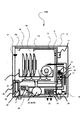
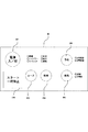
本実施形態に係る食器洗浄機について図1及び図2を参照しながら説明する。図1は、食器洗浄機WMの構成を示す図である。図2は、食器洗浄機WMに組み込まれるCPU29の信号の授受を説明するための図である。食器洗浄機WMは、本体10に洗浄槽40が引き出し可能に収容されている。洗浄槽40内には、かご42が配置されており、かご42に食器や鍋等を置き、その食器等に洗浄水を噴射して洗浄するように構成されている。
A dishwasher according to this embodiment will be described with reference to FIGS. 1 and 2. FIG. 1 is a diagram illustrating a configuration of the dishwasher WM. FIG. 2 is a diagram for explaining the transmission and reception of signals from the
本体10には、第1流路11、洗浄ノズル11a、給水口12、給水バルブ13、水位センサ14、水位センサ15、水位センサ16、フロート17、第2流路18、洗剤投入ノズル18a、温度センサ19、温風ヒータ20、ファン21、吸気口22、洗浄ポンプ23、排水ポンプ24、排水バルブ25、水温センサ26、温水ヒータ27、残菜フィルター28、CPU29(制御手段)、操作パネル30、回転洗浄ノズル31、及び洗剤投入容器41が設けられている。
The
図2に示すように、水位センサ14、水位センサ15、水位センサ16、温度センサ19、及び水温センサ26から出力される信号はインターフェイスを介してCPU29に入力される。CPU29から出力される制御信号はインターフェイスを介して、ファン21、洗浄ポンプ23を駆動するためのモータ231、排水ポンプ24を駆動するためのモータ241、温風ヒータ20、温水ヒータ27、警報機32、給水バルブ13、及び排水バルブ25に出力され、それぞれがその出力された制御信号に応じて作動する。
As shown in FIG. 2, signals output from the
給水バルブ13はCPU29から出力される制御信号に応じて開閉する。給水バルブ13が開かれると、給水口12から洗浄水が洗浄槽40内に供給される。洗浄槽40内に溜められる洗浄水の水位を検出するためにフロート17が配置されている。フロート17は洗浄水に浮かぶように構成されていて、水位センサ16、水位センサ15、水位センサ14と接触して洗浄水の水位を検出できるように構成されている。
The
水位センサ16は、洗浄水が低い水位となっているかを検出するためのセンサであって、主に排水時に的確に排水が行われているかを判断するために用いられる。水位センサ15は、洗浄水が高い水位となっているかを検出するためのセンサであって、主に給水時に的確に給水が行われているかを判断するために用いられる。水位センサ14は、洗浄槽40内の洗浄水が異常に高い水位となっているかを検出するためのセンサであって、例えば給水時に給水バルブ13が開固定状態になってしまい、洗浄水が過剰に供給されることを検出したり、誤った洗剤が投入されて泡が過剰に発生してしまったことを検出したりするために用いられる。このため、各センサは下方から順に、水位センサ16、水位センサ15、水位センサ14の順に配置されている。
The
洗浄槽40の下方には温水ヒータ27が設けられており、温水ヒータ27で加熱された洗浄水は洗浄ポンプ23へと供給される。洗浄ポンプ23は、正回転時には洗浄水を第1流路11に供給し、洗浄ノズル11に向けて圧送する。洗浄ポンプ23は、また正回転時に洗浄水を回転洗浄ノズル31へと圧送する。洗浄ポンプ23は、逆回転時には洗浄水を第2流路18に供給し、洗剤投入ノズル18aに向けて圧送する。
A
洗浄ノズル11は、洗浄槽40の上方に配置されており、洗浄水を上方から食器等へと噴射する。回転洗浄ノズル31は、かご42の下方に配置されており、噴射口が回転することで洗浄水を広角に下方から食器等へと噴射する。洗剤投入ノズル18aは、洗浄槽40の上方に配置されており、洗浄水を洗剤投入容器41へと噴射する。洗剤投入容器41に洗浄水が噴射されると、洗剤投入容器41内に収容されている洗剤が飛び散り又は洗浄水と共に溢れ出て、洗浄槽40内へと供給される。
The cleaning
温水ヒータ27によって加熱される洗浄水の温度を計測するために、温水ヒータ27の近傍に水温センサ26が配置されている。温水ヒータ27の上方には残菜フィルター28が設けられていて、食器等を洗った際に落下する残菜が洗浄ポンプ23側に流れ込まないように構成されている。洗浄ポンプ23と同じ位置には、排水ポンプ24と排水バルブ25とが配置されている。
In order to measure the temperature of the cleaning water heated by the
洗浄槽40内に温風を噴射するためにファン21及び温風ヒータ20が配置されている。ファン21が回転すると吸気口22から空気を吸い込んで温風ヒータ20側に送り込まれ、温風ヒータ20で加熱された後に洗浄槽40内に噴射されて排気口41から排出される。温度センサ19は、この温風の温度を計測するために温風ヒータ20よりも洗浄槽40側に配置されている。
A
警報機32は、異常判定の結果、食器洗浄機WMに異常が発生した場合に、使用者への警報を出すための装置である。
The
操作パネル30は、食器洗浄機WMに対する使用者の指示入力を受け付ける部分である。操作パネル30の一例を図3に示す。図3に示す操作パネル30は、電源ボタン301と、スタートボタン302と、コース選択ボタン303と、乾燥選択ボタン304と、換気選択ボタン305と、予約ボタン306とを備えている。各ボタンを操作した結果の出力信号はCPU29に出力され、CPU29によって適宜制御動作が行われる。
The
電源ボタン301は、食器洗浄機WMの主電源を入れたり、切ったりするためのボタンである。スタートボタン302は、食器洗浄の開始を指示したり、一時停止を指示したりするためのボタンである。コースボタン303は、食器洗浄のコースを指示するためのボタンである。乾燥ボタン304は、食器洗浄後の乾燥のコースを指示するためのボタンである。予約ボタン306は、食器洗浄の時間を予約するためのボタンである。
The
引き続いて、食器洗浄機WMの洗浄動作を図4を参照しながら説明する。図4は、食器洗浄機WMの洗浄動作を説明するためのタイムチャートである。図4に示すように、食器洗浄機WMの洗浄動作は順に、給水工程S41を実行後、食器に付着した食べ物が乾燥固着するのを防止するとともに食べ物を膨潤させて次の本洗浄工程S46で汚れを除去しやすくするための予洗い工程S42を所定時間実行し、その終了後洗浄水を排水工程S43で排水して、給水工程S44でお湯を給水し、洗剤投入工程S45で洗剤を投入後、本洗浄工程S46で本格的な洗浄を開始する。この本洗浄工程S46の終了後、排水工程S47、給水工程S48を経由して、本洗浄工程S46に続いて行われる濯ぎ工程へと移行する。この濯ぎ工程は3つの濯ぎ工程を備えている。具体的には、洗剤が入った洗浄水を排出して綺麗な洗浄水に入れ替えることを目的として短い時間運転される濯ぎ工程1及び2が実行され、その後洗浄水を加熱して高温で本格的に濯ぎ洗浄を行う加熱濯ぎ工程が実行されるように構成されている。その後排水工程S56が実行され、その後乾燥工程S57に移行して一連の制御シーケンスが終了するように構成されている。
Subsequently, the cleaning operation of the dishwasher WM will be described with reference to FIG. FIG. 4 is a time chart for explaining the cleaning operation of the dishwasher WM. As shown in FIG. 4, the washing operation of the dishwasher WM sequentially performs the water supply step S41, and then prevents the food adhering to the tableware from drying and sticking and swells the food in the next main washing step S46. After the pre-washing step S42 for facilitating the removal of dirt is performed for a predetermined time, the washing water is drained in the draining step S43, hot water is fed in the water feeding step S44, and the detergent is fed in the detergent feeding step S45. Then, full-scale cleaning is started in the main cleaning step S46. After the completion of the main cleaning step S46, the process proceeds to the rinsing step performed following the main cleaning step S46 via the drainage step S47 and the water supply step S48. This rinsing step includes three rinsing steps. Specifically, rinsing
以下この制御シーケンスを具体的に説明すると、給水工程S41では、給水バルブ13が開かれて洗浄槽40に水が給水される。給水工程S41における水位は水位センサ16が検知するまでの低めの位置に設定されている。予洗い工程S42では、洗浄ポンプS43が駆動されて、食器等についた大きな残菜が取り除かれるとともに、食器に付着した食べ物を膨潤させている。その後、排水工程S43で排水され、給水工程S44で60度のお湯が給水される。給水工程S44における水位は水位センサ15が検知する高めの位置に設定されている。給水完了後、洗剤投入工程S45で洗浄槽40内に予め格納されている洗剤が投入される。より具体的には、洗浄ポンプ23が低速で逆回転されて、洗浄水が第2流路18を通って洗剤投入ノズル18aから噴射される。洗剤投入ノズル18aは洗剤投入容器41に向けられているので、洗剤投入ノズル18aから噴射された洗浄水は洗剤投入容器41内に収容されている洗剤を、ポンプを低速にしているため大きな飛び散りを抑制しつつ溢れださせることで、洗浄槽40内に洗剤が投入される。洗剤投入工程S45からの本洗浄工程S46においては、温水ヒータ27に通電され、洗浄ポンプ23が高速の正回転で駆動され通常制御として洗浄が行われる。
This control sequence will be specifically described below. In the water supply step S41, the
約20分程度、本洗浄工程S46が継続された後、排水工程S47で洗剤が混じった洗浄水が排水され、綺麗な常温の洗浄水が再度給水工程S48で給水される。給水工程S48における水を節約するために水位は水位センサ16で検知される低めの位置に設定されている。本洗浄工程S46が終了すると濯ぎ工程に移行するが、濯ぎ工程は排給水を繰り返す形で連続3回実行される。最初の濯ぎ工程1S49では、洗浄ポンプ23が駆動されて、洗剤を洗い流す。その後、排水工程S50で洗浄水が排水され、給水工程S51で給水される。給水工程S51における水位は同様に低めの位置に設定されている。濯ぎ工程2S52で洗浄ポンプ23が駆動されて、洗剤を洗い流し、排水工程S53で洗浄水が排水される。この2回の排給水によって洗浄水は洗剤を含まない綺麗なものとすることができる。その後、給水工程S54で60度のお湯が給水される。この給水工程S54における水位は水位センサ15が検知する高めの位置に設定されている。
After the main cleaning step S46 is continued for about 20 minutes, the cleaning water mixed with the detergent is drained in the draining step S47, and the clean room temperature cleaning water is supplied again in the water supplying step S48. In order to save water in the water supply step S48, the water level is set to a lower position detected by the
給水完了後、温水ヒータ27に通電されて更に80度まで洗浄水の温度が高められる。その状態で洗浄ポンプ23が駆動され、本格的な温水による濯ぎ洗浄が実行される。これが加熱濯ぎ工程S55である。この加熱濯ぎ工程は、約20分程度継続され、食器の洗浄は実質的に完了する。その後、排水工程S56で排水し、食器類を乾燥させるための乾燥工程S57に移行する。ここでは、ファン21が回転され、温風ヒータ20に通電されることで、洗浄槽40内に温風が噴射され食器類が乾燥させられる。なお、乾燥工程S57の初期では、洗浄槽40内の余熱を利用するため温風ヒータ20には通電されない。
After the water supply is completed, the
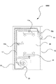
引き続いて、洗浄ポンプ23の回転状態と洗浄ノズル11a及び洗剤投入ノズル18aからの洗浄水の噴射状態とについて、図5を参照しながら説明する。図5は、食器洗浄機WMの洗浄ポンプ23、洗浄ノズル11a及び洗剤投入ノズル18a等について模式的に示した図である。
Subsequently, the rotation state of the
図5に示すように、洗浄ポンプ23が正回転をすると、洗浄水は第1流路11のみに供給される。第1流路11には、回転洗浄ノズル31と、洗浄ノズル11aと、洗浄ノズル11bとが接続されているので、洗浄水が第1流路11に供給されると、回転洗浄ノズル31と、洗浄ノズル11aと、洗浄ノズル11bとからそれぞれ洗浄水が噴射する。
As shown in FIG. 5, when the cleaning
回転洗浄ノズル31は、洗浄槽40の下側に配置されており、上方に向けて洗浄水を噴射するように構成されている。洗浄ノズル11bは、洗浄槽40の中程に配置されており、水平方向からやや上方に向けて洗浄水を噴射するように構成されている。
The
洗浄ノズル11aは、洗浄槽40の上側に配置されており、下方に向けて洗浄水を噴射するように構成されている。洗浄ノズル11aは、噴射する洗浄水が洗剤投入容器41には入らないように構成されている。
The cleaning
洗浄ポンプ23が正回転している場合には、第1流路11に洗浄水が供給されるものの、第2流路18には洗浄水が供給されないように構成されている。この構成について図6を参照しながら説明する。
When the cleaning
洗浄ポンプ23は、ケーシング231の内部に収められている回転子232が回転することで洗浄水に圧力を加え、洗浄水を第1流路11及び第2流路18に送り出している。ケーシング231と第2流路18との接合部分には、遮断弁233が設けられている。遮断弁233は、回転軸233aを中心にして搖動するように構成されている。回転軸233aには、第1弁体233bが繋がっており、第1弁体233bの先端には第2弁体233cが設けられている。第1弁体233bは、回転軸233aを中心に搖動して第2流路18への入り口を閉じるように構成されている。回転軸233aは、洗浄ポンプ23が正回転をした場合に、第1弁体233bに対して上流側に位置するように構成されている。また、第2弁体233cは、第1弁体233bに対して洗浄ポンプ23の中心側に折れ曲がって突出するように構成されている。従って、洗浄ポンプ23が正回転をした場合、洗浄水の水流によって第2弁体233cが洗浄ポンプ23の外側方向に押されて、第1弁体233bが第2流路18への入り口に押しつけられるように構成されている。
The cleaning
続いて、洗浄ポンプ23が逆回転をした場合について図7及び図8を参照しながら説明する。図7に示すように、洗浄ポンプ23が逆回転をすると、洗浄水は第1流路11及び第2流路18の双方に供給される。図6を参照しながら説明したように、洗浄ポンプ23と第1流路11との接合部分には何らの弁も設けられていないので、洗浄ポンプ23が逆回転しても第1流路11には洗浄水が供給される。ただし、洗浄ポンプ23が正回転の場合に比較して、洗浄ポンプ23が逆回転の場合には吐出圧が低下するので、回転洗浄ノズル31、洗浄ノズル11a、及び洗浄ノズル11bからそれぞれ噴射される洗浄水の勢いは弱くなる。このように、回転洗浄ノズル31と、洗浄ノズル11aと、洗浄ノズル11bとからそれぞれ噴射される洗浄水は少なくなるけれども、洗剤を供給する工程においては、それらのノズルから噴射される洗浄水は洗剤が大きく飛散して食器等に付着して固化するのを予防しているものであるため、噴射量を少なくすることが好ましいものである。
Next, the case where the cleaning
図8に示すように、洗浄ポンプ23が逆回転をすると、遮蔽弁233の第2弁体233cが洗浄水の水流によって押されて、第1弁体233bが第2流路18の入り口から離れるように回転する。従って、第2流路18に洗浄水が供給されて、洗剤投入ノズル18aから洗浄水が噴射され、洗剤投入容器41に洗浄水が供給される。尚、遮蔽弁233の回転軸233a近傍にはストッパー234が設けられているので、遮蔽弁233はストッパー234によって支えられて所定の開状態を維持する。
As shown in FIG. 8, when the cleaning
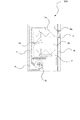
洗剤投入ノズル18aは、噴射する洗浄水が洗剤投入容器41に届くような位置に設けられている。従って、洗剤投入ノズル18aから噴射された洗浄水は洗剤投入容器41に供給される。ここで、洗剤投入容器41について図9〜図11を参照しながら説明する。図9は、食器洗浄機WMの扉43を開いた状態を示す図である。図10は、図9のA−A断面を示す図である。図11は、図9のB−B断面を示す図である。
The
図9及び図10に示すように、扉43を開いてほぼ水平状態にすると、洗剤投入容器41は、開口部41aを上方に向けた状態となる。洗剤投入容器41は、回転軸411によって扉43の内面に軸支されており、その底面には錘部412が設けられている。従って、洗剤投入容器41は、回転軸411を中心として錘部412が下方に位置するように搖動する。このような構成とすることで、図11の(a)に示すように扉43を略水平となるまで開いた場合には、洗剤投入容器41は開口部41aを上方に向けた状態となり、洗剤を投入することができる。また、図11の(b)に示すように扉43を閉じると、洗剤投入容器41は開口部41aを上方に向けた状態となり、開口部41aが洗剤投入ノズル18a側を向くことになって、洗剤投入ノズル18aから噴射された洗浄水が洗剤投入容器41の中に供給される。
As shown in FIGS. 9 and 10, when the
上述した例では、洗浄ポンプ23を逆回転させることで、洗剤投入ノズル18aに洗浄水を供給して、洗浄投入ノズル18aから洗剤投入容器41に洗浄水を噴射したが、洗剤投入ノズル18aから洗剤投入容器41に洗浄水を噴射する態様はこれに限られるものではない。本実施形態の第1の変形例を図12及び図13に示す。
In the above-described example, the cleaning
図12及び図13に示す第1の変形例は、洗浄ポンプ23zは常に正回転をさせており、遮蔽弁は設けずに第2流路18の途中に電磁弁44を設けている。図12に示すように、電磁弁44を閉じて洗浄ポンプ23zを正回転させると、第1流路11のみに洗浄水が供給され、回転洗浄ノズル31と、洗浄ノズル11aと、洗浄ノズル11bとからそれぞれ洗浄水が噴射する。一方、図13に示すように、電磁弁44を開いて洗浄ポンプ23zを正回転させると、第1流路11と第2流路18との双方に洗浄水が供給され、回転洗浄ノズル31と、洗浄ノズル11aと、洗浄ノズル11bとからそれぞれ洗浄水が噴射すると共に、洗剤投入ノズル18aから洗浄水が噴射する。この場合、回転洗浄ノズル31と、洗浄ノズル11aと、洗浄ノズル11bとからそれぞれ噴射される洗浄水は少なくなるけれども、洗剤を供給する工程においては、それらのノズルから噴射される洗浄水は洗剤が食器等に付着するのを予防し、また付着したのを落とすためであるから、噴射量が少なくなっても問題はない。
In the first modification shown in FIGS. 12 and 13, the cleaning
続いて、本実施形態の第2の変形例を図14及び図15に示す。図14及び図15に示す第2の変形例は、洗浄ポンプ23zを常に正回転させており、その回転数を変更することで洗浄水の噴射を制御している。図14に示すように、洗浄ポンプ23zを低い回転数で正回転させると、第1流路11及び第2流路18にそれぞれ洗浄水が供給される。しかしながら、洗浄ポンプ23zの回転数が低く洗浄水の吐出圧が低いので、回転洗浄ノズル31、洗浄ノズル11a、洗浄ノズル11b、及び洗剤投入ノズル18aから噴射される洗浄水は少ない状態である。従って、回転洗浄ノズル31、洗浄ノズル11a、及び洗浄ノズル11bから噴射される洗浄水が洗剤投入容器41に届かないのはもちろんのこと、洗剤投入ノズル18aから噴射される洗浄水も洗剤投入容器41に届かない。
Subsequently, a second modification of the present embodiment is shown in FIGS. In the second modification shown in FIGS. 14 and 15, the
一方、図15に示すように、洗浄ポンプ23zの回転数を上げて正回転させると、高い吐出圧で洗浄水が第1流路11及び第2流路18に供給される。このため、洗剤投入ノズル18aから噴射される洗浄師が洗剤投入容器41に届き、洗剤投入ノズル18aから噴射された洗浄水が洗剤投入容器41の中に供給される。
On the other hand, as shown in FIG. 15, when the rotational speed of the
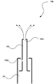
洗浄ポンプ23zからの洗浄水の吐出圧を変更する態様では、洗剤投入ノズル18aの代わりに図16及び図17に示す洗剤投入ノズル18bを用いてもよい。図16及び図17に示す洗剤投入ノズル18bは、支持体181と、ノズル182とによって構成されている。ノズル182は、細長い円筒状の形態を成しており、支持体181に対して進退自在に構成されていて、その先端に第1噴射孔182aが、円筒状となっている筒の途中には第2噴射孔182bがそれぞれ設けられている。
In the aspect of changing the discharge pressure of the cleaning water from the
図16に示すように、洗浄ポンプ23zから洗剤投入ノズル18bに供給される洗浄水の吐出圧が低い場合には、ノズル182は支持体181の内部に半分程度納まった状態となっていて、第2噴射孔182bは支持体181の内部に隠れた状態となっている。従って、この状態では第1噴射孔182aからのみ洗浄水が噴射される。
As shown in FIG. 16, when the discharge pressure of the cleaning water supplied from the
一方、図17に示すように、洗浄ポンプ23zから洗剤投入ノズル18bに供給される洗浄水の吐出圧が高い場合には、ノズル182は支持体181から更に突出した状態となり、第2噴射孔182bは支持体181の外部に出た状態となる。従って、この状態では、第1噴射孔182aからのみならず、第2噴射孔182bからも洗浄水が噴射する。図17に示す状態の場合に、第2噴射孔182bから噴射される洗浄水が届く位置に洗剤投入容器を配置すれば、洗浄ポンプ23zからの洗浄水の吐出圧の変更によって、確実に洗剤投入容器に洗浄水を供給して、洗剤を飛び散らせたり洗浄水と共に溢れださせたりすることが可能となる。
On the other hand, as shown in FIG. 17, when the discharge pressure of the cleaning water supplied from the
WM…食器洗浄機、10…本体、40…洗浄槽、11…第1流路、11a…洗浄ノズル、12…給水口、13…給水バルブ、14…水位センサ、15…水位センサ、16…水位センサ、17…フロート、18…第2流路、18a…洗剤投入ノズル、19…温度センサ、20…温風ヒータ、21…ファン、22…吸気口、23…洗浄ポンプ、24…排水ポンプ、25…排水バルブ、26…水温センサ、27…温水ヒータ、28…残菜フィルター、29…CPU、30…操作パネル、31…回転洗浄ノズル、41…洗剤投入容器、42…かご、43…扉。
DESCRIPTION OF SYMBOLS WM ... Tableware washing machine, 10 ... Main body, 40 ... Washing tank, 11 ... 1st flow path, 11a ... Washing nozzle, 12 ... Water supply port, 13 ... Water supply valve, 14 ... Water level sensor, 15 ... Water level sensor, 16 ...
Claims (6)
洗剤を前記洗浄槽に投入するために設けられ、前記洗浄ノズルが噴射する洗浄水がその内部に入らないように構成されている洗剤投入容器と、
前記洗剤投入容器に洗浄水を供給できる位置に設けられた洗剤投入ノズルと、
前記洗剤投入ノズルからの洗浄水の供給を制御するための制御手段と、を備える食器洗浄機であって、
前記制御手段は、所定の洗剤投入タイミングにおいて前記洗剤投入ノズルに洗浄水を供給することで、前記洗剤投入容器に収容されている洗剤を洗浄水中に溶かすように制御することを特徴とする食器洗浄機。 A cleaning nozzle that injects cleaning water onto an object to be cleaned such as tableware disposed in the cleaning tank;
A detergent charging container which is provided for charging detergent into the cleaning tank and configured so that the cleaning water sprayed by the cleaning nozzle does not enter the interior;
A detergent charging nozzle provided at a position where cleaning water can be supplied to the detergent charging container;
A dishwasher comprising: control means for controlling the supply of washing water from the detergent charging nozzle,
The control means controls to dissolve the detergent contained in the detergent charging container into the cleaning water by supplying cleaning water to the detergent charging nozzle at a predetermined detergent charging timing. Machine.
前記洗剤投入ノズルに洗浄水を供給するための流路と、
前記流路に洗浄水を供給するための洗浄ポンプと、
前記洗浄ポンプから前記流路への洗浄水の供給口を開閉するための遮断弁と、を備えることを特徴とする請求項1に記載の食器洗浄機。 The detergent charging container is disposed at the top of the washing tank, and the detergent charging nozzle is disposed close to the detergent charging container,
A flow path for supplying cleaning water to the detergent charging nozzle;
A cleaning pump for supplying cleaning water to the flow path;
The dishwasher according to claim 1, further comprising: a shut-off valve for opening and closing a supply port of the cleaning water from the cleaning pump to the flow path.
前記ノズルは、前記洗剤投入タイミングにおいて伸びることで前記洗剤投入容器に近接し、前記洗剤投入ノズルとして機能することを特徴とする請求項1に記載の食器洗浄機。 Comprising a telescopic nozzle that functions as the cleaning nozzle;
2. The dishwasher according to claim 1, wherein the nozzle extends at the detergent charging timing to approach the detergent charging container and functions as the detergent charging nozzle.
前記流路に洗浄水を供給するための洗浄ポンプと、を備え、
前記洗浄ポンプの吐出圧を高めることで前記ノズルを伸ばすことを特徴とする請求項3に記載の食器洗浄機。 A flow path for supplying cleaning water to the nozzle;
A cleaning pump for supplying cleaning water to the flow path,
The dishwasher according to claim 3, wherein the nozzle is extended by increasing a discharge pressure of the washing pump.
前記洗剤投入ノズルに洗浄水を供給するための洗浄ポンプを備え、
前記洗浄ポンプの吐出圧を高めることで前記洗剤投入ノズルから噴射される洗浄水が前記洗剤投入容器に届くように構成されていると共に、前記洗浄ポンプの吐出圧が低い場合には前記洗剤投入ノズルから噴射される洗浄水が前記洗剤投入容器に届かないように構成されていることを特徴とする請求項1に記載の食器洗浄機。 The detergent charging nozzle is directed toward the detergent charging container and is arranged downward from the top surface of the cleaning tank,
A cleaning pump for supplying cleaning water to the detergent charging nozzle;
The cleaning water sprayed from the detergent charging nozzle is configured to reach the detergent charging container by increasing the discharge pressure of the cleaning pump, and when the discharge pressure of the cleaning pump is low, the detergent charging nozzle The dishwasher according to claim 1, wherein the washing water sprayed from the container does not reach the detergent charging container.
Priority Applications (1)
| Application Number | Priority Date | Filing Date | Title |
|---|---|---|---|
| JP2007255509A JP2009082394A (en) | 2007-09-28 | 2007-09-28 | Dishwasher |
Applications Claiming Priority (1)
| Application Number | Priority Date | Filing Date | Title |
|---|---|---|---|
| JP2007255509A JP2009082394A (en) | 2007-09-28 | 2007-09-28 | Dishwasher |
Publications (1)
| Publication Number | Publication Date |
|---|---|
| JP2009082394A true JP2009082394A (en) | 2009-04-23 |
Family
ID=40656666
Family Applications (1)
| Application Number | Title | Priority Date | Filing Date |
|---|---|---|---|
| JP2007255509A Pending JP2009082394A (en) | 2007-09-28 | 2007-09-28 | Dishwasher |
Country Status (1)
| Country | Link |
|---|---|
| JP (1) | JP2009082394A (en) |
Cited By (1)
| Publication number | Priority date | Publication date | Assignee | Title |
|---|---|---|---|---|
| CN111050625A (en) * | 2018-02-21 | 2020-04-21 | 松下知识产权经营株式会社 | Tableware cleaning machine |
-
2007
- 2007-09-28 JP JP2007255509A patent/JP2009082394A/en active Pending
Cited By (2)
| Publication number | Priority date | Publication date | Assignee | Title |
|---|---|---|---|---|
| CN111050625A (en) * | 2018-02-21 | 2020-04-21 | 松下知识产权经营株式会社 | Tableware cleaning machine |
| CN111050625B (en) * | 2018-02-21 | 2024-02-02 | 松下知识产权经营株式会社 | Tableware cleaning machine |
Similar Documents
| Publication | Publication Date | Title |
|---|---|---|
| TWI581745B (en) | Dish | |
| JP2009082393A (en) | Dishwasher | |
| JP2009082392A (en) | Dishwasher | |
| US7998280B2 (en) | Method of controlling dishwasher and dishwasher | |
| JP2009131512A (en) | Dishwasher | |
| JP2009082394A (en) | Dishwasher | |
| JP2009165578A (en) | Dish washer | |
| JP2010263941A (en) | Dishwasher | |
| JP2001112686A (en) | Dishwasher | |
| JP4206261B2 (en) | Dishwasher and method for supplying detergent | |
| JP3867809B1 (en) | Dishwasher | |
| JP2009183378A (en) | Dishwasher | |
| JP4780791B2 (en) | dishwasher | |
| JP2007301176A (en) | Dishwasher | |
| JP2007325789A (en) | Dishwasher | |
| JP6998784B2 (en) | Dishwasher | |
| JP6629075B2 (en) | washing machine | |
| JP3777505B2 (en) | Dishwasher | |
| JP6068891B2 (en) | Dishwasher | |
| JP4988490B2 (en) | Dishwasher | |
| JP2005329068A (en) | Dish washer | |
| JP2004321403A (en) | Dishwasher | |
| JP3985398B2 (en) | Dishwasher | |
| KR100198615B1 (en) | Detergent inputting method of a dishwasher | |
| JP2005253623A (en) | Dishwasher |