JP2009081008A - Lighting state display device, and lighting state display system - Google Patents
Lighting state display device, and lighting state display system Download PDFInfo
- Publication number
- JP2009081008A JP2009081008A JP2007248507A JP2007248507A JP2009081008A JP 2009081008 A JP2009081008 A JP 2009081008A JP 2007248507 A JP2007248507 A JP 2007248507A JP 2007248507 A JP2007248507 A JP 2007248507A JP 2009081008 A JP2009081008 A JP 2009081008A
- Authority
- JP
- Japan
- Prior art keywords
- discharge lamp
- output
- display
- lighting
- infrared
- Prior art date
- Legal status (The legal status is an assumption and is not a legal conclusion. Google has not performed a legal analysis and makes no representation as to the accuracy of the status listed.)
- Pending
Links
Images


Abstract
Description
この発明は、調光制御される放電灯の出力状態を表示する点灯状態表示装置に関する。 The present invention relates to a lighting state display device that displays an output state of a discharge lamp that is dimmed and controlled.
近年の省エネへの取り組みは、各業界で様々な形態で行われている。照明装置(照明器具)に至っては、施設に必ず設置され、且つ、施設で使用している電力の大半を消費している。このため、省エネ効果を上げるためには、照明装置の照度を適切に設定することが望ましい。現在まで連続調光機能や段調光機能を持った照明器具を設置することにより、省エネ効果が得られてきた(例えば特許文献1)。 In recent years, energy conservation efforts have been carried out in various forms in each industry. The lighting device (lighting fixture) is always installed in the facility and consumes most of the electric power used in the facility. For this reason, in order to raise an energy-saving effect, it is desirable to set the illumination intensity of an illuminating device appropriately. Up to now, an energy saving effect has been obtained by installing a lighting device having a continuous light control function and a step light control function (for example, Patent Document 1).
上記のように連続調光や段調光された照明器具の点灯状態、即ち点灯しているランプの明るさをランプが装着されている照明器具を見ただけで判断することは難しい。更に点灯状態を表示するためには専用の表示装置が必要であり、高価であった。
この発明は、簡易な構成、かつ低コストで、調光制御されている放電灯の点灯状態を検出して表示する点灯状態表示装置の提供を目的とする。 An object of the present invention is to provide a lighting state display device that detects and displays a lighting state of a discharge lamp that is dimmed and controlled with a simple configuration and low cost.
この発明の点灯状態表示装置は、
出力を調光制御される放電灯が発生した光を受光し、受光した前記放電灯の光に含まれる赤外線を検出する赤外線検出部と、
前記放電灯の出力状態を表示する表示部と、
前記赤外線検出部によって検出された赤外線の検出結果に基づいて前記放電灯の前記出力状態を判定し、前記出力状態の判定結果に基づいて前記放電灯の前記出力状態を前記表示部に表示させる表示制御部と
を備えたことを特徴とする。
The lighting state display device of the present invention is
An infrared detector that receives light generated by a discharge lamp whose output is dimmed and detects infrared rays included in the received light of the discharge lamp; and
A display for displaying the output state of the discharge lamp;
A display for determining the output state of the discharge lamp based on the detection result of the infrared ray detected by the infrared detection unit, and displaying the output state of the discharge lamp on the display unit based on the determination result of the output state And a control unit.
この発明により、簡易な構成、かつ低コストで、調光制御されている放電灯の点灯状態を検出して表示する点灯状態表示装置を提供できる。 According to the present invention, it is possible to provide a lighting state display device that detects and displays the lighting state of a discharge lamp that is controlled in light control with a simple configuration and at low cost.
実施の形態1.
図1〜図6を用いて実施の形態1を説明する。実施の形態1は、調光制御されている放電灯から赤外線を受光し、受光した赤外線の検出結果に基づいて放電灯の出力状態を判定し、判定した出力状態を表示する出力表示器(点灯状態表示装置)に関する。この出力表示器により、簡単な構成で放電灯の点灯状態を知ることができる。以下、図を参照して実施の形態1を説明する。
The first embodiment will be described with reference to FIGS. In the first embodiment, an infrared ray is received from a discharge lamp under dimming control, an output state of the discharge lamp is determined based on a detection result of the received infrared ray, and the determined output state is displayed (lighting) Status display device). With this output indicator, it is possible to know the lighting state of the discharge lamp with a simple configuration. The first embodiment will be described below with reference to the drawings.
図1は、実施の形態1における照明システム1000(点灯状態表示システム)を示す図である。照明システム1000は、自己に装着されたランプ(放電灯)を調光制御可能な照明器具110a〜110dと、出力表示器200aとを備える。各照明器具は、後述の放電灯点灯装置100aを備えている。
FIG. 1 is a diagram showing an illumination system 1000 (lighting state display system) in the first embodiment. The lighting system 1000 includes lighting fixtures 110a to 110d capable of dimming and controlling a lamp (discharge lamp) mounted on the lighting system 1000, and an
図2は、照明システム100の配線を示した図である。図2は、照明器具110a〜110d、電源スイッチ2(壁スイッチ)、及び出力表示器200aの配線関係を示す配線図である。図2は図1に対応し、電源スイッチ2はスイッチボックス300に収納され、出力表示器200aはスイッチボックス280に収納された場合を示している。出力表示器200aは、後述する図4に示す構成であるが、図2では3つのLEDと赤外線受光窓(フォトダイオード211)のみを示して簡略化している。出力表示器200aは、赤外線受光部にて放電灯の発する赤外線を受光し、受光した赤外線の検出結果に基づいて放電灯の出力状態を判定し、判定結果をLEDの点灯状態として表示する。例えば、出力表示器200aは、放電灯の出力状態が高出力(明るい)と判定した場合は3つのLEDを点灯させ、放電灯の出力状態が中程度の出力と判定した場合は2つのLEDを点灯させ、放電灯の出力状態が低度の出力(暗め)と判定した場合は1つのみLEDを点灯させる。出力表示器200aは放電灯からの赤外線を受光して制御するものであるから、照明器具から見通しのよい位置に配置することが好ましいが、必ずしも全ての照明器具を見通しできる位置に配置する必要はない。
FIG. 2 is a diagram illustrating wiring of the illumination system 100. FIG. 2 is a wiring diagram showing a wiring relationship among the lighting fixtures 110a to 110d, the power switch 2 (wall switch), and the
図2に示すように、複数の照明器具110a〜110dは、交流電源1に並列に接続している。そして、出力表示器200aは、交流電源1に対して照明器具と並列に接続する。また、出力表示器200aは、スイッチボックス280に格納され、壁に配置される。
As shown in FIG. 2, the plurality of lighting fixtures 110 a to 110 d are connected to the
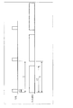
図3は、壁に埋め込まれたスイッチボックス280(出力表示器200aを格納している)の構造を示す図である。図3(a)は正面図であり、図3(b)は、A−A断面図である。A−A断面図では出力表示器200aの内部構造は省略してある。図3は、図2に示す出力表示器200aの具体的な形態を示している。出力表示器200aを1個用スイッチボックス280に収納し、表面に表示素子であるLEDを配置し、また、放電灯からの赤外線を受光する受光窓(フォトダイオードが組み込まれている)を設けてある。
FIG. 3 is a diagram showing the structure of a switch box 280 (containing the
図4は、放電灯点灯装置100aと、出力表示器200aとの回路構成を示す図である。図4は図1に対応する。上記のように、図1の各照明器具110a等は、放電灯点灯装置100aを備えている。図4は、例えば照明器具110aの備える放電灯点灯装置100aを抜き出して、出力表示器200aと共に回路構成を示した場合である。
FIG. 4 is a diagram showing a circuit configuration of the discharge lamp lighting device 100a and the
次に図4を用いて放電灯点灯装置100a、出力表示器200aの構成を説明する。なお、本実施の形態の特徴は出力表示器200aにあるので、放電灯点灯装置100aは、簡単に説明する。
Next, the configuration of the discharge lamp lighting device 100a and the
(放電灯点灯装置100aの構成)
まず、放電灯点灯装置100aを説明する。放電灯点灯装置100aは、整流回路10、アクティブフィルタ回路20、インバータ回路30、負荷回路40、制御電源回路50、電源同期回路60、ドライブ回路70、不揮発性メモリ81を備えたマイクロコンピュータ80、ランプ検出回路90を備える。マイクロコンピュータは、以下、マイコンという場合がある。
(1)整流回路10は、ダイオードブリッジである。整流回路10は、電源電圧の整流、及び、ノイズの除去を行う回路である。
(2)アクティブフィルタ回路20は、チョークコイル21、ダイオード22、コンデンサ23、スイッチング素子24を備える。アクティブフィルタ回路20は、電源電圧波形に沿ってスイッチング素子24によりスイッチングを行うことにより、電源電圧を所定の直流電圧に昇圧すると共に入力電流波形を整形して力率を改善する回路である。
(3)インバータ回路30は、アクティブフィルタ回路20で昇圧された直流電圧を、ドライブ回路70から出力される逆極性の電圧でスイッチング素子31、32を交互にスイッチングすることにより、高周波電圧を発生させる回路である。
(4)負荷回路40は、インダクタ41、放電灯42、コンデンサ43、45、抵抗44を備える。負荷回路40は、インダクタ41、コンデンサ43の共振を利用して、放電灯42(以下、ランプという場合がある)を点灯させる回路である。
(5)ドライブ回路70は、マイコン80から出力される制御信号に基づき、インバータ回路30のスイッチング素子31,32を交互にスイッチングさせる回路である。
(6)電源同期回路60は、商用電源(交流電源1)のON、OFF(電源スイッチ2のオン、オフ)を検出する回路である。
(7)ランプ検出回路90は、商用電源(交流電源1)から抵抗33インダクタ41、ランプフィラメント、抵抗44、ランプフィラメントを介して、ランプの有無を検出する回路である。ランプ検出回路90は、ランプ(放電灯42)が装着されている場合にはHレベルを出力し、ランプ(放電灯42)が装着されていない場合にはLレベルを出力する。マイコン80は、ランプ検出回路90からHレベル信号あるいはLレベル信号を入力することにより、放電灯42が装着されているかどうかを判定可能である。
(8)制御電源回路50は、マイコン80を駆動する電源回路である。制御電源回路50は、商用電源(交流電源1)がOFFされた後も、5秒程度はマイコン80が動作できる電力を保持する回路である。
(9)マイコン80は、インバータ回路30の周波数制御および電源同期回路60から送される電源ON、OFF信号の判定などを行う。放電灯点灯装置100aでは、マイコン80が、電源スイッチ2のON、OFF操作を検出し、ON、OFF操作に対応した放電灯の出力モードを設定し、その設定した出力モードで放電灯を点灯させる。出力表示器200aは、その調光制御された放電灯の赤外線を検出して、出力状態をLEDに表示する。具体的には、マイコン80は、プログラムされた所定の電源スイッチ2のON,OFF操作を検出すると、予めプログラム組み込まれているプログラムに従って、所定の出力モードを設定し、設定した出力モードに対応する「制御信号」をドライブ回路70に出力する。ドライブ回路70は、マイコン80から制御信号を入力すると、制御信号に従ってインバータ回路30のスイッチング素子31,32を駆動する。これによりインバータ回路30が所定の発振周波数で発振し、放電灯が前記制御信号に対応する出力で点灯する。これにより、放電灯42が調光制御される。
(Configuration of discharge lamp lighting device 100a)
First, the discharge lamp lighting device 100a will be described. The discharge lamp lighting device 100a includes a
(1) The
(2) The
(3) The
(4) The
(5) The
(6) The power
(7) The
(8) The control
(9) The
(マイコン80による調光制御方式)
図5を参照してマイコン80による調光制御方式を説明する。図5に示すように、放電灯点灯装置100aの動作状態で、電源スイッチ2の所定の操作を行う。ここで「電源スイッチ2の所定の操作」とは、図5に示すように、「0.1s以上3s以内のOFF」(A)の後、「0.1s以上3s以内のON」(B)、さらにその後「0.1s以上3s以内のOFF」(C)の操作をいう。この「電源スイッチ2の所定の操作」を行うことにより、その後(操作(C)の後)の3s後に所定の出力設定となる。マイコン80の動作で説明すれば次の様である。電源同期回路60は電源スイッチ2のON、OFFを検出し、ON、OFFに対応した信号をマイコン80に出力する。マイコン80は、電源同期回路60から入力した信号に基づき、図5に示す「電源スイッチ2の所定の操作」かどうかを判定する。マイコン80は、「電源スイッチ2の所定の操作」と判定した場合は、操作(C)終了後から3秒が経過したときに、予め設定されている調光率に対応する制御信号を生成してドライブ回路70に出力し、ドライブ回路70にインバータ回路30を駆動させる。
(Dimming control method by microcomputer 80)
A dimming control method by the
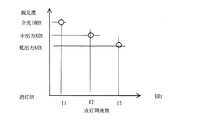
図6は、放電灯の点灯周波数と調光度の関係を示す図である。マイコン80は、予め設定されている調光率として図6のようなテーブルを不揮発性メモリ81に備えており、このテーブルに従ってドライブ回路70に出力する制御信号を生成する。マイコン80は、例えば、「電源スイッチ2の所定の操作」を検出するごとに調光率を全光、中出力、低出力、全光、中出力、低出力・・・と循環するように設定する。
FIG. 6 is a diagram showing the relationship between the lighting frequency of the discharge lamp and the dimming degree. The
(出力表示器200aの構成)
出力表示器200aは、赤外線検出部210aと、マイコン220(表示制御部)と、表示部230aと、表示器電源240とを備える。
(1)赤外線検出部210aは、フォトダイオード211、プリアンプ212、抵抗、複数のフィルタ回路215を備えている。フォトダイオード211は、点灯状態を表示する対象となる放電灯が発生する赤外線を受光して電気信号に変換する。プリアンプ212は、フォトダイオード211により変換された信号を増幅する。各フィルタ回路は、赤外線検出部210aの出力した信号を入力し、特定の周波数の信号を通過させる。
(2)表示部230aは、複数のLEDから構成される。
(3)マイコン220は、フィルタ回路を通過した信号の強度と周波数とから放電灯の点灯状態(出力状態)を判断し、点灯状態を表示部230aに表示させる。また、マイコン220は不揮発性メモリ221を備える。
(4)表示器電源240は、マイコン220や表示素子であるLED、赤外線検出部210の電源となる。
(Configuration of
The
(1) The infrared detection unit 210a includes a photodiode 211, a preamplifier 212, a resistor, and a plurality of filter circuits 215. The photodiode 211 receives infrared rays generated by a discharge lamp that is a target for displaying a lighting state, and converts the received infrared rays into an electrical signal. The preamplifier 212 amplifies the signal converted by the photodiode 211. Each filter circuit receives a signal output from the infrared detector 210a and passes a signal having a specific frequency.
(2) The display unit 230a includes a plurality of LEDs.
(3) The
(4) The display power supply 240 is a power supply for the
(出力表示器200aの動作)
出力表示器200aは、図1のように、通常、調光制御機能を有する複数の照明器具とともに使用されるが、照明器具は1台の場合でも構わない。
(1)まず、赤外線検出部210aのフォトダイオード211が、調光制御可能な放電灯の発した光に含まれる赤外線を受光し、電気信号に変換する。
(2)プリアンプ212は、フォトダイオード211により変換された電気信号を増幅する。
(3)プリアンプ212により増幅された電気信号は、それぞれのフィルタ回路に入力され、フィルタ特性に合致する周波数の信号がマイコン220に入力される。
(4)マイコン220は、フィルタ回路から入力した信号の周波数及び強度とに基づいて、放電灯の出力状態を判定し(マイコン220は判定基準を不揮発性メモリ221に格納している)、判定結果に従って、LEDを点灯させる。例えば、マイコン220は、フィルタ回路1(放電灯は高出力とする)から信号が入力された場合にはLED1〜LED3を全部点灯させ、フィルタ回路2(放電灯は中出力とする)から入力された場合にはLED1、LED2を点灯させ、フィルタ回路3(放電灯は低出力とする)から入力された場合にはLED1のみ点灯させる制御を行なう。
(Operation of
As shown in FIG. 1, the
(1) First, the photodiode 211 of the infrared detection unit 210a receives infrared light included in light emitted from a discharge lamp capable of dimming control, and converts it into an electrical signal.
(2) The preamplifier 212 amplifies the electrical signal converted by the photodiode 211.
(3) The electric signal amplified by the preamplifier 212 is input to each filter circuit, and a signal having a frequency matching the filter characteristics is input to the
(4) The
以上の出力表示器200aにより、調光制御される放電灯の調光状態を簡単な構成で表示できる出力表示器を提供することができる。
The
実施の形態2.
図7を参照して実施の形態2を説明する。実施の形態2は、2段調光をおこなう放電灯点灯装置100bと、出力表示器200bとを備えた照明システムを説明する。システム構成は図1と同様である。放電灯点灯装置100bは、実施の形態1の放電灯点灯装置100aと調光制御方式(出力設定方式)が異なる。出力表示器200bは、実施の形態1の出力表示器200bに対して、フィルタ回路が2つ及びLEDが2つとなっており、他は出力表示器200aと同様である。
The second embodiment will be described with reference to FIG.
(放電灯点灯装置100bによる調光制御)
放電灯点灯装置100bは、段調光制御回路91の端子に電源が印加されるか否かで2段の「段調光」で放電灯を点灯制御(調光制御)する。スイッチ92のON、OFFにより段調光制御回路91の端子に電源の印加がON、OFFされる。段調光制御回路91は、この電源の印加のON、OFFに対して、ONに対応するON対応信号、OFFに対応するOFF対応信号のいずれかをマイコン80に出力する。マイコン80は、段調光制御回路91が出力したON対応信号、OFF対応信号に基づき、制御信号を生成してドライブ回路70に出力する。ドライブ回路70は、この制御信号に従ってインバータ回路30のスイッチング素子31,32を駆動する。これにより放電灯の段調光が行なわれる。
(Dimming control by the discharge lamp lighting device 100b)
The discharge lamp lighting device 100b performs lighting control (dimming control) of the discharge lamp by two-stage “dimming” depending on whether power is applied to the terminal of the step dimming
(出力表示器200bによる表示動作)
出力表示器200bによる表示動作は、実施の形態1の出力表示器200aと同様である。すなわち、出力表示器200bは、放電灯点灯装置100bにより調光制御される放電灯の放つ赤外線を受光することにより、出力状態を表示する。
(Display operation by the output display 200b)
The display operation by the output indicator 200b is the same as that of the
実施の形態3.
図8〜図10を参照して実施の形態3を説明する。実施の形態3は、放電灯点灯装置100cが、点灯周波数を連続変化させて「連続調光」させる場合である。
Embodiment 3 FIG.
The third embodiment will be described with reference to FIGS. The third embodiment is a case where the discharge lamp lighting device 100c performs “continuous dimming” by continuously changing the lighting frequency.
(放電灯点灯装置100cの構成)
実施の形態3の放電灯点灯装置100cは、調光信号を送信する調光装置110から調光信号を受信して、受信した調光信号をマイコン80が検知可能な信号に変換してマイコン80に出力する連続調光制御回路93を備える。また、図9は、調光装置110が送信する調光信号を示す。図9は、放電灯を全光させる場合は、調光装置110はデューティ比「t1:T」の調光信号を送信し、放電灯を25%調光させる場合は、デューティ比「t2:T」の調光信号を送信することを示している。マイコン80は、調光信号を受信した連続調光制御回路93から、連続調光制御回路93が受信した調光信号に対応する信号であって連続調光制御回路93により変換された変換信号を入力する。マイコン80は、入力した変換信号に従って制御信号を生成しドライブ回路70に出力する。図10は、点灯周波数と点灯状態の関係を示す。マイコン80は図10に示すようなテーブルを不揮発性メモリ221に格納しており、入力した変換信号と前記テーブルとに基づき制御信号を生成し出力する。
(Configuration of discharge lamp lighting device 100c)
The discharge lamp lighting device 100c of Embodiment 3 receives the dimming signal from the dimming
(出力表示器200cの構成)
出力表示器200cは、フィルタ回路を設けることなく、プリアンプ212の出力を直接マイコン220に印加するように構成してある。マイコン220は、印加されたプリアンプ212からの信号を周波数分析し、現在の放電灯の点灯周波数を算出する。マイコン220は、放電灯について予め設定されている調光点灯状態と点灯周波数との関係を不揮発性メモリ221に格納しており、算出した点灯周波数をもとに格納している調光点灯状態と点灯周波数との関係から、現在の点灯状態を特定する。マイコン220は、点灯状態を特定すると、例えば7セグメント方式の表示素子で構成された表示部230cに、現在の調光点灯状態を数値表示する。
(Configuration of output display 200c)
The output indicator 200c is configured to apply the output of the preamplifier 212 directly to the
実施の形態4.
図11,図12を参照して実施の形態4を説明する。実施の形態4は、放電灯点灯装置100dが、放電灯の出力設定方法として「ON−OFF段調光制御」を行なう場合を説明する。出力表示器200bが、その調光制御方式で調光制御された放電灯の出力状態を表示する。出力表示器200bは、実施の形態2と同一の構成であるので説明は省略する。
Embodiment 4 FIG.
The fourth embodiment will be described with reference to FIGS. In the fourth embodiment, a case where the discharge lamp lighting device 100d performs “ON-OFF stage dimming control” as a discharge lamp output setting method will be described. The output display 200b displays the output state of the discharge lamp that is dimmed and controlled by the dimming control method. Since the output display 200b has the same configuration as that of the second embodiment, the description thereof is omitted.
放電灯点灯装置100dは、図11に示すように、ON−OFF段調光制御回路部94とスイッチ95を備えている。スイッチ95がONとなると、ON−OFF段調光制御回路部94は、マイコン80に「ON−OFF段調」を実行することを指令する指令信号を出力する。マイコン80はON−OFF段調光制御回路部94から指令信号を入力すると、図12に示すように、人間がチラツキとして感じない周期Tの内t時間のみ放電灯を点灯させる制御信号を生成してドライブ回路70に出力する。ドライブ回路70は、入力した制御信号に従って、図12の点灯状態となるべき発振周波数でインバータ回路30のスイッチング素子31,32を駆動する。これにより放電灯42が調光制御される。出力表示器200bは、この調光制御された放電灯の放つ赤外線を受光することにより、出力状態を表示する。
As shown in FIG. 11, the discharge lamp lighting device 100 d includes an ON-OFF stage dimming
1 交流電源、2 電源スイッチ、3 配線、10 整流回路、20 アクティブフィルタ回路、21 チョークコイル、22 ダイオード、23 コンデンサ、24 スイッチング素子、30 インバータ回路、31,32 スイッチング素子、33 抵抗、40 負荷回路、41 インダクタ、42 放電灯、43 コンデンサ、44 抵抗、45 コンデンサ、50 制御電源回路、60 電源同期回路、70 ドライブ回路、80 マイコン、81 不揮発性メモリ、90 ランプ検出回路、100a,100b,100c,100d 放電灯点灯装置、110a,110b,110c,110d 照明器具、200a,200b,200c 出力表示器、210a,210b,210c 赤外線検出部、211 フォトダイオード、212 プリアンプ、220 マイコン、221 不揮発性メモリ、230a,230b,230c 表示部、240 表示器電源、280,300 スイッチボックス、1000 照明システム。
1 AC power supply, 2 power switch, 3 wiring, 10 rectifier circuit, 20 active filter circuit, 21 choke coil, 22 diode, 23 capacitor, 24 switching element, 30 inverter circuit, 31, 32 switching element, 33 resistance, 40 load circuit , 41 inductor, 42 discharge lamp, 43 capacitor, 44 resistor, 45 capacitor, 50 control power supply circuit, 60 power supply synchronization circuit, 70 drive circuit, 80 microcomputer, 81 non-volatile memory, 90 lamp detection circuit, 100a, 100b, 100c, 100d discharge lamp lighting device, 110a, 110b, 110c, 110d lighting fixture, 200a, 200b, 200c output indicator, 210a, 210b, 210c infrared detector, 211 photodiode, 212
Claims (5)
前記放電灯の出力状態を表示する表示部と、
前記赤外線検出部によって検出された赤外線の検出結果に基づいて前記放電灯の前記出力状態を判定し、前記出力状態の判定結果に基づいて前記放電灯の前記出力状態を前記表示部に表示させる表示制御部と
を備えたことを特徴とする点灯状態表示装置。 An infrared detector that receives light generated by a discharge lamp whose output is dimmed and detects infrared rays included in the received light of the discharge lamp; and
A display for displaying the output state of the discharge lamp;
A display for determining the output state of the discharge lamp based on the detection result of the infrared ray detected by the infrared detection unit, and displaying the output state of the discharge lamp on the display unit based on the determination result of the output state A lighting state display device comprising a control unit.
検出した赤外線を前記表示制御部に出力し、
前記表示制御部は、
前記赤外線検出部から赤外線を入力し、入力した赤外線の強度と周波数とに基づいて、前記放電灯の前記出力状態を判定することを特徴とする請求項1記載の点灯状態表示装置。 The infrared detector is
Output the detected infrared rays to the display control unit,
The display control unit
2. The lighting state display device according to claim 1, wherein infrared light is input from the infrared detection unit, and the output state of the discharge lamp is determined based on the intensity and frequency of the input infrared light.
出力を調光制御される複数の放電灯が発生した光を受光し、受光した光に含まれる赤外線を検出し、
前記表示制御部は、
前記赤外線検出部によって検出された赤外線の検出結果に基づいて前記複数の放電灯の出力状態を判定し、前記出力状態の判定結果に基づいて前記複数の放電灯の前記出力状態を前記表示部に表示させることを特徴とする請求項1または2のいずれかに記載の点灯状態表示装置。 The infrared detector is
Receives light generated by multiple discharge lamps whose output is dimmed and detects infrared rays contained in the received light.
The display control unit
The output state of the plurality of discharge lamps is determined based on a detection result of infrared rays detected by the infrared detection unit, and the output state of the plurality of discharge lamps is displayed on the display unit based on the determination result of the output state. The lighting state display device according to claim 1, wherein the lighting state display device is displayed.
少なくとも一つの発光ダイオードを備え、
前記表示制御部は、
前記放電灯の前記出力状態の表示として、前記発光ダイオードの点灯を制御することを特徴とする請求項1〜3のいずれかに記載の点灯状態表示装置。 The display unit
Comprising at least one light emitting diode,
The display control unit
The lighting state display device according to claim 1, wherein lighting of the light emitting diode is controlled as the display of the output state of the discharge lamp.
前記請求項1〜4のいずれかに記載の点灯状態表示装置と
を備えたことを特徴とする点灯状態表示システム。 A lighting fixture capable of dimming and controlling the discharge lamp attached to the self;
A lighting state display system comprising the lighting state display device according to any one of claims 1 to 4.
Priority Applications (1)
| Application Number | Priority Date | Filing Date | Title |
|---|---|---|---|
| JP2007248507A JP2009081008A (en) | 2007-09-26 | 2007-09-26 | Lighting state display device, and lighting state display system |
Applications Claiming Priority (1)
| Application Number | Priority Date | Filing Date | Title |
|---|---|---|---|
| JP2007248507A JP2009081008A (en) | 2007-09-26 | 2007-09-26 | Lighting state display device, and lighting state display system |
Publications (1)
| Publication Number | Publication Date |
|---|---|
| JP2009081008A true JP2009081008A (en) | 2009-04-16 |
Family
ID=40655604
Family Applications (1)
| Application Number | Title | Priority Date | Filing Date |
|---|---|---|---|
| JP2007248507A Pending JP2009081008A (en) | 2007-09-26 | 2007-09-26 | Lighting state display device, and lighting state display system |
Country Status (1)
| Country | Link |
|---|---|
| JP (1) | JP2009081008A (en) |
Cited By (2)
| Publication number | Priority date | Publication date | Assignee | Title |
|---|---|---|---|---|
| JP2011009058A (en) * | 2009-06-25 | 2011-01-13 | Panasonic Electric Works Co Ltd | Wall switch |
| WO2016031361A1 (en) * | 2014-08-27 | 2016-03-03 | シャープ株式会社 | Lighting device |
-
2007
- 2007-09-26 JP JP2007248507A patent/JP2009081008A/en active Pending
Cited By (3)
| Publication number | Priority date | Publication date | Assignee | Title |
|---|---|---|---|---|
| JP2011009058A (en) * | 2009-06-25 | 2011-01-13 | Panasonic Electric Works Co Ltd | Wall switch |
| WO2016031361A1 (en) * | 2014-08-27 | 2016-03-03 | シャープ株式会社 | Lighting device |
| CN106605448A (en) * | 2014-08-27 | 2017-04-26 | 夏普株式会社 | Lighting device |
Similar Documents
| Publication | Publication Date | Title |
|---|---|---|
| JP6399525B2 (en) | System and method for providing automatic adjustment of a light source | |
| US11297701B2 (en) | Switch based lighting control | |
| JP2014509053A (en) | Lighting driver for light-emitting diode lamps compatible with electromagnetic ballast | |
| KR101423403B1 (en) | Illumination device | |
| KR101124478B1 (en) | dimming control apparatus for LED lighting system that being adjustable illuminance | |
| KR20110091444A (en) | Led drive circuit, dimming device, led illumination fixture, led illumination device, and led illumination system | |
| JP2010092776A (en) | Led driving circuit, led illumination fixture, led illumination equipment, and led illumination system | |
| KR101657474B1 (en) | A LED Unit for Automatic Control of Intensity of Illumination | |
| US8816604B2 (en) | Dimming control method and apparatus for LED light source | |
| JP4785804B2 (en) | Discharge lamp lighting device, lighting fixture, lighting system, and output indicator | |
| US20100072909A1 (en) | System for Field-Programmed Determination of Illumination Set Points in Ballasts | |
| JP2008262891A5 (en) | ||
| TWI392399B (en) | Light adjusting device for a light emitting diode and related light adjusting method and light emitting device | |
| KR101743064B1 (en) | Led dimming control apparatus | |
| CN103120028A (en) | Device and method for automatically detecting installed lamp type | |
| JP2009081008A (en) | Lighting state display device, and lighting state display system | |
| JP4356940B2 (en) | Dimming sensor device and lighting fixture used in lighting fixture with electronic ballast | |
| JP2008204849A (en) | Automatic dimming lighting system | |
| JP5041945B2 (en) | Light source state detection device and lighting fixture | |
| JP2006310258A (en) | Fluorescent lamp lighting device and lighting control system | |
| KR100946692B1 (en) | Automatic Lighting Control System and Method for control lighting the same | |
| JP5376867B2 (en) | Illumination lighting device, luminaire, and illumination system | |
| JP2006019244A (en) | Fluorescent lamp lighting device | |
| KR20090001199U (en) | Illumination apparatus with Emergency Light function | |
| JP2004335109A (en) | High-frequency lighting device and illumination device |