JP2009073610A - Post-processing device and image forming system - Google Patents
Post-processing device and image forming system Download PDFInfo
- Publication number
- JP2009073610A JP2009073610A JP2007243537A JP2007243537A JP2009073610A JP 2009073610 A JP2009073610 A JP 2009073610A JP 2007243537 A JP2007243537 A JP 2007243537A JP 2007243537 A JP2007243537 A JP 2007243537A JP 2009073610 A JP2009073610 A JP 2009073610A
- Authority
- JP
- Japan
- Prior art keywords
- post
- sheet
- unit
- processing
- sheets
- Prior art date
- Legal status (The legal status is an assumption and is not a legal conclusion. Google has not performed a legal analysis and makes no representation as to the accuracy of the status listed.)
- Pending
Links
Images


Abstract
Description
本発明は、画像形成装置に連結可能で、前記画像形成装置から排出される用紙を所定の枚数の用紙束にして後処理を行う後処理装置および、画像形成装置に前記後処理装置を接続してなる画像形成システムに関する。 The present invention relates to a post-processing apparatus that can be connected to an image forming apparatus, performs post-processing by making a predetermined number of sheets discharged from the image forming apparatus, and connects the post-processing apparatus to the image forming apparatus. The present invention relates to an image forming system.
複写機やプリンタ等の画像形成装置より排紙された画像記録済の用紙に穴あけ処理や綴じ処理等の後処理を行う後処理装置がある。 There is a post-processing device that performs post-processing such as punching processing and binding processing on image-recorded paper discharged from an image forming apparatus such as a copying machine or a printer.
このような後処理装置は、画像形成装置に接続されて画像形成システムを構成し、画像形成装置のコピーまたはプリント等の画像形成プロセスのシーケンス作動に連動して動作するようになっている。 Such a post-processing apparatus is connected to the image forming apparatus to constitute an image forming system, and operates in conjunction with a sequence operation of an image forming process such as copying or printing of the image forming apparatus.
従って画像形成プロセスを高速で処理することの可能な画像形成装置に対しては、画像形成装置の処理速度に追従して機能を果すことの出来る高速処理の可能な後処理装置が必要とされる。 Therefore, for an image forming apparatus capable of processing an image forming process at high speed, a post-processing apparatus capable of high-speed processing capable of performing a function following the processing speed of the image forming apparatus is required. .
後処理装置が行う後処理には、画像形成装置より排紙される画像記録済の用紙を、グループにまとめて行うものがある。例えば、用紙に綴じ針(ステイプル)を打針して綴じて冊子を形成する製本処理では、打針を行う前に、用紙を冊子毎のグループにまとめることが行われる。 As post-processing performed by the post-processing device, there is a method in which image-recorded sheets discharged from the image forming device are grouped together. For example, in a bookbinding process in which a booklet is formed by binding a staple (staple) on a sheet to form a booklet, the sheets are grouped into groups for each booklet before the needle is printed.
このような製本処理を行う製本手段部には、冊子にする用紙を順次積載するスタッカと、用紙に打針を行って綴じるステイプラと、を有し、先ず、スタッカに冊子にする用紙を順次載置して1冊分のグループを形成し、形成されたグループにステイプラにて打針を行って冊子を形成する。このような、後処理が行われる用紙のグループを、以下、用紙束と記すことにする。 The bookbinding means for performing such a bookbinding process includes a stacker for sequentially stacking sheets to be booklet and a stapler for stapling the sheets and binding them. First, the sheets to be booklet are sequentially placed on the stacker. Then, a group for one book is formed, and the formed group is hit with a stapler to form a booklet. Such a group of sheets to be post-processed is hereinafter referred to as a sheet bundle.
複数部の冊子を形成する場合には、先ず1部目の冊子となる用紙束をスタッカ上に形成して、用紙束に打針を行って冊子に形成し、形成した冊子をスタッカから排出した後に2部目の冊子となる用紙をスタッカに順次積載して2番目の用紙束を形成し、打針処理を行う。以後、3部目の冊子の用紙束の形成と打針、4部目の冊子の冊子の用紙束の形成と打針、・・と用紙束の形成と打針とが連続して行われる。 In the case of forming a multi-part booklet, a sheet bundle as a first-part booklet is first formed on the stacker, a needle is applied to the sheet bundle to form a booklet, and the formed booklet is ejected from the stacker. Sheets to be used as the second set of booklets are sequentially stacked on the stacker to form a second sheet bundle, and a needle punching process is performed. Thereafter, the formation and punching of the sheet bundle of the third set of booklets, the formation and punching of the sheet bundle of the booklet of the fourth set of booklets,...
画像形成装置や後処理装置においては、単位時間当たりの用紙の処理枚数(以下、生産性とも記す)が多いことが望まれる。 In image forming apparatuses and post-processing apparatuses, it is desired that the number of sheets processed per unit time (hereinafter also referred to as productivity) be large.
近年、画像形成装置の生産性は、画像形成装置内の用紙搬送速度や、画像形成プロセス速度の向上により大幅に向上し、画像形成装置が連続して画像形成した用紙を排出する時間間隔が短くなって来ている。画像形成装置が連続して画像形成した用紙を排出する時間間隔は、画像形成装置の生産性を示す尺度として重要であり、以下連続排紙時間間隔と称し、tCで表すことにする。 In recent years, the productivity of image forming apparatuses has been greatly improved by improving the paper conveyance speed in the image forming apparatus and the image forming process speed, and the time interval at which the image forming apparatus continuously discharges the image-formed sheets is short. It is becoming. The time interval at which the image forming apparatus discharges continuously formed sheets of paper is important as a measure indicating the productivity of the image forming apparatus, and is hereinafter referred to as a continuous discharge time interval and is represented by t C.
一方、後処理装置の生産性を図る手段として、後処理装置内の用紙の搬送速度を画像形成装置内の搬送速度より増速することが行われているが、後処理装置の用紙の搬送速度の増速も限界があり、また後処理の種別によっては処理そのものに要する時間の短縮が困難なものもある。例えば前述の、製本処理は、スタッカ上の用紙束に打針し、形成された冊子を排出するが、時間の短縮が困難な後処理の一つである。 On the other hand, as a means for improving the productivity of the post-processing apparatus, the paper transport speed in the post-processing apparatus is increased from the transport speed in the image forming apparatus. However, there are some cases where it is difficult to reduce the time required for the processing itself depending on the type of post-processing. For example, the bookbinding process described above is one of the post-processes in which it is difficult to shorten the time, although the booklet on the stacker is stapled and the formed booklet is discharged.
製本処理は、用紙束を構成する末尾の用紙をスタッカに順次載置することによる用紙束の形成、用紙束の整合、打針による冊子の形成、形成された冊子のスタッカからの排出、を一連の動作としてなされる。 The bookbinding process consists of a series of steps: forming the stack of sheets by sequentially placing the last sheet of the stack of sheets on the stacker, aligning the stack of sheets, forming a booklet by punching, and discharging the formed booklet from the stacker. Made as an action.
製本処理を連続して行う場合には、用紙のスタッカへの載置、用紙束の形成、整合、打針、スタッカからの排出が繰り返されることになる。そして、複数の用紙束に連続して製本処理を行うときには、後続の用紙束を構成する用紙のスタッカへの搬送、載置は、先行する用紙束が製本されてスタッカから排出された後に行われる。 When the bookbinding process is continuously performed, the placement of the sheets on the stacker, the formation of the sheet bundle, the alignment, the needle hitting, and the discharge from the stacker are repeated. When the bookbinding process is continuously performed on a plurality of sheet bundles, conveyance and placement of the sheets constituting the subsequent sheet bundle are performed after the preceding sheet bundle is bound and discharged from the stacker. .
この、先行する用紙束を構成する末尾の用紙をスタッカへ載置した時点から、後続の用紙がスタッカに載置可能になる時点までの時間は、後処理装置の生産性を示す尺度として重要であり、これを後処理実行動作時間と称することとし、tFで表すことにする。そして、後処理実行動作時間tFの短縮は、画像形成装置でなされた連続排紙時間間隔tCの短縮に比して顕著ではないのが現状である。 The time from when the last sheet constituting the preceding sheet bundle is placed on the stacker to when the subsequent sheet can be placed on the stacker is important as a measure of the productivity of the post-processing apparatus. Yes, this is referred to as post-processing execution operation time, and is represented by t F. The shortening of the post-processing execution operation time t F is not as significant as the shortening of the continuous paper discharge time interval t C made in the image forming apparatus.
後処理装置は、画像形成装置から順次排出される用紙を順次受け入れて、後処理を行うように構成される。 The post-processing apparatus is configured to sequentially receive sheets sequentially discharged from the image forming apparatus and perform post-processing.
以下、図11乃至図13に基づいて画像形成装置から排出される4枚の用紙を用紙束にして冊子を形成する後処理を複数の用紙束に連続して行うときを例にして、画像形成装置の連続排紙時間間隔tCと後処理装置の後処理実行動作時間tFとの関連を説明する。なお、tBとは1つの用紙束を構成する用紙の枚数であり、図中の数字1、2、3、・・・は、それぞれの用紙束を構成する用紙が画像形成装置から続排紙時間間隔tCで排紙される順序を示したものである。
In the following, image forming is performed by taking as an example a case where post-processing for forming a booklet by forming a bundle of four sheets discharged from the image forming apparatus based on FIGS. The relationship between the continuous paper discharge time interval t C of the apparatus and the post-processing execution operation time t F of the post-processing apparatus will be described. T B is the number of sheets constituting one sheet bundle, and
図11は、従来の画像形成システムにおける後処理装置の後処理実行動作時間tFが画像形成装置の連続排紙時間間隔tCよりも長いとき、例えば連続排紙時間間隔tCの2倍であるときの動作を説明する図である。連続排紙時間間隔tCが後処理実行動作時間tFより短いときは、図に示されるように、後処理装置内の先行の用紙束の後処理が終了する前に、後処理部の用紙束形成部(スタッカ)に後続用紙束の用紙が搬送されることになる。しかし、後処理装置後の処理手段部は後処理が終了する以前に画像形成装置から排出される用紙をスタッカに受け入れることはできないので、2束目の1枚目の用紙をスタッカに搬送することができない。すなわち、2束目以降の用紙束の用紙を後処理装置に排出することができない。このような状態を回避するために、画像形成装置からの用紙の排出を後処理装置の後処理実行動作時間tFに合わせて行うことが行われる。 FIG. 11 shows that when the post-processing execution operation time t F of the post-processing apparatus in the conventional image forming system is longer than the continuous paper discharge time interval t C of the image forming apparatus, for example, twice the continuous paper discharge time interval t C. It is a figure explaining operation | movement at a time. When the continuous paper discharge time interval t C is shorter than the post-processing execution operation time t F , as shown in the figure, before the post-processing of the preceding paper bundle in the post-processing device is finished, the paper in the post-processing section The sheets of the subsequent sheet bundle are conveyed to the bundle forming unit (stacker). However, since the processing unit after the post-processing apparatus cannot accept the paper discharged from the image forming apparatus before the post-processing is finished, the second sheet of the first sheet is conveyed to the stacker. I can't. That is, the sheets in the second and subsequent bundles cannot be discharged to the post-processing device. In order to avoid such a state, the sheet is discharged from the image forming apparatus in accordance with the post-processing execution operation time t F of the post-processing apparatus.
図12は、従来の画像形成システムにおける画像形成装置からの2束目以降の用紙束の先頭となる用紙の排出を、後処理装置の後処理実行動作時間tFに合わせて遅らせるように構成したときの動作を説明する図である。図12においては、2束目以降の用紙束の先頭となる用紙の排出を、連続排紙時間間隔tCよりもtW分遅らせている。 FIG. 12 shows a configuration in which the discharge of a sheet at the head of the second and subsequent sheet bundles from the image forming apparatus in the conventional image forming system is delayed in accordance with the post-processing execution operation time t F of the post-processing apparatus. It is a figure explaining operation | movement at the time. In FIG. 12, the discharge of the leading sheet in the second and subsequent bundles is delayed by t W from the continuous discharge time interval t C.
このように構成することにより、後処理実行動作時間tFが画像形成装置の連続排紙時間間隔tCよりも長い場合でも、先行の用紙束の後処理を実行中の後処理手段部に、後続の用紙が搬送される不具合を回避することができる。しかし、画像形成装置は連続排紙時間間隔tCにての排紙が行われないので、単位時間当たりの用紙の処理枚数(生産性)が低下することになり、画像形成システムとして動作させるときに、画像形成装置の高い生産性を享受できないことになる。 With this configuration, even when the post-processing execution operation time t F is longer than the continuous paper discharge time interval t C of the image forming apparatus, the post-processing unit that is performing the post-processing of the preceding sheet bundle can It is possible to avoid the problem that the subsequent sheet is conveyed. However, since the image forming apparatus does not discharge paper at the continuous paper discharge time interval t C, the number of processed paper sheets (productivity) per unit time is reduced, and the image forming apparatus is operated as an image forming system. In addition, the high productivity of the image forming apparatus cannot be enjoyed.
ところで、用紙束に後処理を行うに際し、所定の枚数の用紙を重ね合わせて集積する集積部を設け、画像形成された用紙を集積部に集積し、集積した用紙を後処理手段部に搬送する技術が開示されている(特許文献1、特許文献2)。複数枚の用紙を重ね合わせてから搬送することにより、用紙が画像形成されてから、重ねた枚数分の用紙が画像形成される時間が経過した後に後処理手段部に搬送することができる。例えば重ね合わせ枚数を2とし、2枚の用紙を重ね合わせてから後処理手段部に搬送することにより、通常の搬送時間に対してさらに1枚分の用紙が画像形成される時間に相当する時間が経過した後に、搬送することができる。すなわち、画像形成装置は所定の時間間隔で排出された用紙は、集積部にて後続の用紙と重ね合わせてから搬送されることにより、画像形成装置から排出される時間間隔よりも長い時間が経過した後に後処理手段部に搬送される。
By the way, when the post-processing is performed on the sheet bundle, a stacking unit that stacks and stacks a predetermined number of sheets is provided, stacks the image-formed sheets in the stacking unit, and transports the stacked sheets to the post-processing unit. Techniques are disclosed (
したがって、後処理装置における後処理実行動作時間tFが画像形成装置の連続排紙時間間隔tCよりも長い場合でも、先行の用紙束に対する後処理を実行中の後処理手段部に、後続の用紙が搬送される不具合を回避することが可能になり、画像形成システムを、画像形成装置の生産性を落とさずに動作させることができる。すなわち、後処理装置における後処理実行動作時間tFと、画像形成装置の連続排紙時間間隔tCとの時間差を後処理手段部に搬送する用紙を重ね合わせることにより整合させて、画像形成装置の生産性を落とさずに画像形成システムを動作させることを可能にする。この、集積部から重ね合わされて排出される複数の用紙を用紙組と称することにする。 Therefore, even when the post-processing execution operation time t F in the post-processing apparatus is longer than the continuous paper discharge time interval t C of the image forming apparatus, It is possible to avoid a problem that the sheet is conveyed, and the image forming system can be operated without reducing the productivity of the image forming apparatus. That is, the time difference between the post-processing execution operation time t F in the post-processing device and the continuous paper discharge time interval t C of the image forming device is matched by superimposing the paper transported to the post-processing unit, and the image forming device It is possible to operate the image forming system without reducing the productivity. The plurality of sheets that are superposed and discharged from the stacking unit are referred to as a sheet set.
図13は、後処理装置の後処理実行動作時間tFが画像形成装置の連続排紙時間間隔tCの2倍であるときに、用紙組を構成する用紙の枚数nSが2枚である集積部を設けた場合の動作を説明する図である。図に示されるように、後処理装置は重ね合わせた枚数分の用紙分の時間tCを確保できる。したがって後処理装置は、後処理実行動作時間tFが画像形成装置の連続排紙時間間隔tCよりも長い場合でも、後処理実行動作時間tFを確保でき、画像形成装置から連続排紙時間間隔tCにて排出される用紙に後処理を行うことができる。
しかし、近年の高速化においては画像形成装置の用紙の搬送速度および用紙の排紙間隔が短くなっているために、後処理実行動作時間tFを確保することが難しくなっている。 However, with the recent increase in speed, it is difficult to secure the post-processing execution operation time t F because the paper conveyance speed and the paper discharge interval of the image forming apparatus are shortened.
用紙の重ね合わせ枚数を3枚あるいはそれ以上に増加させることにより後処理実行動作時間tFを確保することは可能である。しかしその一方で、用紙組を構成する用紙の枚数が多い場合には用紙組を搬送することにより用紙間のズレ、不揃いが生じやすくなり、後処理の品質の低下を惹起することがあった。 It is possible to secure the post-processing execution operation time t F by increasing the number of stacked sheets to 3 or more. On the other hand, however, when the number of sheets constituting the sheet set is large, the sheet set is likely to be misaligned or uneven due to the conveyance of the sheet set, resulting in a decrease in post-processing quality.
本発明は前記背景を踏まえてなされたもので、集積部における重ね合わせ枚数を少なくして高品質の後処理を画像形成装置の生産性を落とさず行う後処理装置を提供することを課題にする。 SUMMARY An advantage of some aspects of the invention is that it provides a post-processing device that performs high-quality post-processing without reducing the productivity of the image forming apparatus by reducing the number of overlapping sheets in the stacking unit. .
上記の課題は、以下に記載する手段により達成される。
(1)画像形成装置から排出される用紙を所定の枚数重ね合わせて用紙組を形成する集積部と、
当該集積部にて形成された用紙組を順次集積して用紙束を形成し、形成した用紙束に後処理を行う後処理部と、
前記集積部から排出された用紙組を前記後処理部に搬送する連結搬送部と、
制御手段と、
を有し、前記画像形成装置に接続可能である後処理装置において、
前記連結搬送部は、用紙組を、第1の搬送時間にて搬送する第1の動作モード、あるいは、第1の搬送時間より長い第2の搬送時間にて搬送する第2の動作モードにて搬送することが可能であることを特徴とする後処理装置。
(2)画像形成した用紙を所定の時間間隔にて順次排出する画像形成装置と、画像形成された用紙を用紙束にして後処理を行う(1)に記載の後処理装置と、を接続して成ることを特徴とする画像形成システム。
Said subject is achieved by the means described below.
(1) a stacking unit that forms a sheet set by overlapping a predetermined number of sheets discharged from the image forming apparatus;
A post-processing unit that sequentially stacks the sheet sets formed in the stacking unit to form a sheet bundle, and performs post-processing on the formed sheet bundle;
A connected conveyance unit that conveys the sheet set discharged from the stacking unit to the post-processing unit;
Control means;
In a post-processing apparatus that can be connected to the image forming apparatus,
In the first operation mode for transporting the sheet set in the first transport time or in the second operation mode for transporting the paper set in the second transport time longer than the first transport time. A post-processing device characterized in that it can be transported.
(2) An image forming apparatus that sequentially discharges image-formed sheets at a predetermined time interval and a post-processing apparatus described in (1) that performs post-processing on a sheet bundle of image-formed sheets are connected. An image forming system comprising:
本発明によれば、集積部における重ね合わせ枚数を少なくして高品質の後処理を画像形成装置の生産性を落とさず行う後処理装置を提供できる。 According to the present invention, it is possible to provide a post-processing apparatus that performs high-quality post-processing without reducing the productivity of the image forming apparatus by reducing the number of overlapping sheets in the stacking unit.
本発明を実施の形態に基づいて説明するが、本発明は本実施の形態に限定されるものではない。 Although the present invention will be described based on the embodiments, the present invention is not limited to the embodiments.
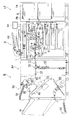
図1は、本発明の実施の形態である後処理装置Bと画像形成装置Aと大容量給紙装置LTとを接続して成る画像形成システムの全体構成図である。なお後処理装置Bは、中間搬送部B1と、後処理部B2とを備える。 FIG. 1 is an overall configuration diagram of an image forming system formed by connecting a post-processing apparatus B, an image forming apparatus A, and a large-capacity paper feeding apparatus LT according to an embodiment of the present invention. The post-processing apparatus B includes an intermediate transport unit B1 and a post-processing unit B2.
[画像形成装置A]
図示の画像形成装置Aは、画像読取部1、画像書込部3、画像形成部4、給紙搬送部5、定着装置6、自動原稿送り装置A2、操作表示部A4を備えている。
[Image forming apparatus A]
The illustrated image forming apparatus A includes an
画像形成部4は、感光体ドラム4A、帯電部4B、現像部4C、転写部4D、分離部4E、クリーニング部4F等から構成されている。
The
給紙搬送部5は給紙カセット5A、第1給紙部5B、第2給紙部5C、搬送部5D、排紙部5E、自動両面コピー給紙装置(ADU)5Fを備えている。
The sheet feeding / conveying
操作表示部A4は液晶パネルで構成される表示部にタッチスクリーンを重ねて配置したタッチパネルを備えている。操作表示部A4により各種操作画面を表示したり、後処理の種類又は給紙カセット5Aに収納させる用紙の種類情報を入力したりすることができる。 The operation display unit A4 includes a touch panel in which a touch screen is arranged on a display unit configured by a liquid crystal panel. Various operation screens can be displayed on the operation display unit A4, and post-processing type or paper type information stored in the paper feed cassette 5A can be input.
自動原稿送り装置A2の原稿台上に載置された原稿は画像読取部1の光学系により原稿の片面又は両面の画像が読みとられ、光電変換されたアナログ信号は、A/D変換、シェーディング補正、画像圧縮処理等の処理を経た後に画像書込部3に送られる。
The document placed on the document table of the automatic document feeder A2 is read on one or both sides of the document by the optical system of the
画像書込部3においては、半導体レーザからの出力光が画像形成部4の感光体ドラム4Aに照射され、潜像を形成する。画像形成部4においては、帯電、露光、現像、転写、分離、クリーニング等の処理が行われる。
In the
第1給紙部5Bにより搬送(給送)された用紙は転写部4Dにより画像が用紙に転写され、用紙は、定着装置6により定着される。定着された用紙は、排紙部5Eから後処理装置Bに送り込まれる。また、用紙の両面に画像形成を行う場合には、定着後の片面画像処理済みの用紙は自動両面コピー給紙装置5Fにて表裏を反転された後再び画像形成部4に送られて画像形成され、定着後に排紙部5Eにより排出され、後処理装置Bに送り込まれる。
An image of the sheet conveyed (supplied) by the first sheet feeding unit 5B is transferred to the sheet by the
画像形成装置Aは、連続して用紙に画像形成するとき、所定サイズの用紙を連続排紙時間間隔tCにて排出する。 When the image forming apparatus A continuously forms images on paper, the image forming apparatus A discharges paper of a predetermined size at a continuous paper discharge time interval t C.
[大容量給紙装置LT]
大容量給紙装置LTは、用紙積載部7A、第1給紙部7B等から成る。用紙積載部7Aには、A4判サイズ、A3判サイズ等の用紙を大量に収納することが可能である。用紙積載部7Aの収納用紙を連続して搬送して画像形成装置Aに送り込む。
[Large capacity feeder LT]
The large capacity sheet feeder LT includes a
[後処理装置B]
前述のように、本実施の形態における後処理装置Bは、用紙の重ね合わせを行う中間搬送部B1と、後処理(製本)を行う後処理部B2とからなる。なお、本実施の形態においては、中間搬送部B1は、後処理部B2とは独立した筐体に組み込まれた形態に構成されているが、中間搬送部B1と後処理部B2とを同一の筐体に組み込んだ形態としても良い。
[Post-processing device B]
As described above, the post-processing apparatus B according to the present embodiment includes the intermediate conveyance unit B1 that superimposes sheets and the post-processing unit B2 that performs post-processing (binding). In the present embodiment, the intermediate transport unit B1 is configured in a form incorporated in a housing independent of the post-processing unit B2, but the intermediate transport unit B1 and the post-processing unit B2 are the same. It is good also as a form incorporated in the housing | casing.
<中間搬送部B1>
中間搬送部B1は、用紙搬入部11、集積部12、用紙搬出部13、バイパス搬送部14から構成されている。中間搬送部B1は、画像形成装置Aから搬送された用紙を集積部12で、複数枚重ねることが可能であり、複数枚の用紙は重ねたまま、かつ、後述するように、画像形成装置Aから排紙された姿勢から表裏が反転されて、後続の後処理部B2に搬送することができる。ここで、集積部12に収納され、重ね合わされて排出される複数の用紙を、用紙組、と記することにする。集積部12が、特許請求の範囲に記した、「画像形成装置から排出される用紙を所定の枚数重ね合わせて用紙組を形成する集積部」に相当する。そして、後処理を行う用紙は集積部12を経由して用紙組となり、後続の後処理部B2に搬送される。
<Intermediate transport section B1>
The intermediate transport unit B1 includes a paper carry-in
また、後処理が不要な用紙、あるいは、表裏反転の必要のない用紙は、集積部12を経由せずにバイパス搬送部14を経由して、後続の後処理部B2に搬送することができる。中間搬送部B1についての詳細は後述する。
Further, paper that does not require post-processing or paper that does not need to be turned upside down can be transported to the subsequent post-processing section B2 via the
<後処理部B2>
後処理部B2には、入口搬送部20、排紙搬送部30、連結搬送部40、差込紙給紙部50、製本手段部70、折り部80が配置されている。
<Post-processing unit B2>
In the post-processing unit B2, an
入口搬送部20、排紙搬送部30、連結搬送部40は、それぞれ、後処理部B2における入口搬送路r20、排紙搬送路r30、連結搬送路r40に配置されており、それぞれの搬送路にて用紙を搬送する。なお、入口搬送路r20、排紙搬送路r30、連結搬送路r40の詳細については、後に図4を用いて説明する。
The
製本手段部70はスタック部60とステイプラ71とを有し、スタック部60にて用紙をスタック(堆積)して用紙束とし、スタック部60上の用紙束の所定位置にステイプラ71にて綴じ針を打針して冊子に形成するものであり、特許請求の範囲に記した、「用紙を集積して所定の枚数の用紙束を形成し、形成した用紙束に後処理を行う後処理部」に相当する。
The bookbinding means
また、後処理部B2の図示左側面には、可動の排紙皿91および固定の排紙皿92が配置されている。
A
中間搬送部B1からの用紙は、後処理部B2の入口搬送路r20に受け入れられる。入口搬送路r20の下流は排紙搬送路r30と連結搬送路r40に分岐している。分岐点には搬送路切換部G20が配置されており、入口搬送路r20を搬送されてきた用紙は、後処理を行うか否かにより搬送路切換部G20により排紙搬送路r30か、連結搬送路r40の何れかに搬送されるようになっている。 The sheet from the intermediate transport unit B1 is received in the entrance transport path r20 of the post-processing unit B2. The downstream of the entrance conveyance path r20 branches into a discharge conveyance path r30 and a connection conveyance path r40. A conveyance path switching unit G20 is disposed at the branching point, and the sheet conveyed through the entrance conveyance path r20 is discharged by the conveyance path switching unit G20 according to whether or not post-processing is performed. It is conveyed to any one of the paths r40.
後処理を行わない場合には、中間搬送部B1から受け入れた用紙を入口搬送路r20から排紙搬送路r30に導き、排紙搬送路r30を経て排紙皿91に排出する。
When the post-processing is not performed, the sheet received from the intermediate conveyance unit B1 is guided from the entrance conveyance path r20 to the discharge conveyance path r30, and is discharged to the
後処理(製本処理)を行う場合は、中間搬送部B1の集積部12を経て受け入れた用紙組を入口搬送路r20から連結搬送路r40を経て、製本手段部70に搬送する。そして、製本手段部70のスタック部60にて用紙組をスタック(堆積)して所定の枚数の用紙束を形成し、ステイプラ71にて用紙束の所定位置に打針して冊子に形成する。
When post-processing (bookbinding processing) is performed, the sheet set received through the stacking
製本処理における打針が用紙束の片側になされる片側綴じの場合、冊子は排紙皿91へ排出される。また打針が用紙束の中央部になされる中綴じの場合、冊子を折り部80にて中折りし排紙皿92へ排出される。
In the case of one-sided binding in which the staple in the bookbinding process is performed on one side of the sheet bundle, the booklet is discharged to the
製本処理が行われる用紙束の末尾となる用紙、またはそれを含む用紙組が製本手段部70のスタック部60に載置されるとステイプラ71にて用紙束の所定位置に打針が行われる。そして、用紙束の末尾となる用紙、またはそれを含む用紙組が製本手段部70のスタック部60に載置された時点から、用紙束に打針がなされて形成した冊子が排出されるまでの間は、後続の用紙束はスタック部60に載置することはできない。先行の用紙束の末尾となる用紙、またはそれを含む用紙組がスタック部60に載置されてから、後続の用紙束の用紙組がスタック部60に載置可能になるまでの時間が前述の後処理実行動作時間となる。
When a sheet at the end of a sheet bundle to be bound, or a sheet set including the sheet bundle is placed on the stack unit 60 of the
本実施の形態における連結搬送部40は、用紙を製本手段部70に送付するに際して、第1の搬送時間で搬送する第1の動作モード、あるいは、第1の搬送時間より長い第2の搬送時間で搬送する第2の動作モードのいずれかにて動作することが可能である。連結搬送部40が、第1の動作モード、あるいは、第2の動作モードで動作するかは、受け入れた用紙の内容に基づいてなされる制御手段の指示による。この、連結搬送部40の動作の詳細は後述する。
In the present embodiment, the
なお、本実施の形態における後処理部B2が行う後処理は、用紙束に綴じ針を打針して冊子を形成する製本処理であるが、用紙束を一括して処理する後処理であれば綴じ針を使用する製本処理に限定されるものではなく、例えば、糊付けにより冊子を形成する製本処理でも良い。また、用紙束を一括して処理する後処理機能以外に、穴あけや、シフトなどの付加機能を備えたものでも良い。 Note that the post-processing performed by the post-processing unit B2 in the present embodiment is a bookbinding process in which a binding needle is applied to a sheet bundle to form a booklet. The bookbinding process is not limited to the bookbinding process using a needle. For example, a bookbinding process in which a booklet is formed by gluing may be used. Further, in addition to a post-processing function for processing a bundle of sheets at once, an additional function such as punching or shifting may be provided.
図2は中間搬送部B1の正面断面図であり、図3は中間搬送部B1の集積部12周辺での駆動手段を示す断面図である。図2、図3に基づいて、中間搬送部B1での用紙重ね合わせ動作について説明する。
FIG. 2 is a front cross-sectional view of the intermediate transport unit B1, and FIG. 3 is a cross-sectional view showing driving means around the stacking
中間搬送部B1は、前述のとおり、用紙搬入部11、集積部12、用紙搬出部13、バイパス搬送部14から構成されている。
As described above, the intermediate transport unit B1 includes the paper carry-in
用紙搬入部11は、搬送ローラR1,R2及びガイド板111を有する用紙搬送路r11を備えている。用紙搬入部11において、画像形成装置Aの排紙部5Eから排出される用紙が順次受容されて搬送される。
The paper carry-in
集積部12は、平行に配置された2枚のガイド板121、停止部材123と縦整合部材124とを有する縦整合部、横整合部材122、及び搬入駆動ローラR3、搬出駆動ローラR4、用紙搬送路r12を備えている。集積部12において、用紙搬入部11から受け入れた複数枚の用紙は重ね合わせた状態で収納されて整合されたのち、上方に排出される。
The stacking
用紙搬出部13は、中間搬送ローラR5、排紙ローラ対(搬送ローラ対)R6(R6a、R6b)、R7(R7a、R7b)及びガイド板131を有する用紙搬送路r13に配置される。用紙搬出部13において、集積部12に収納された複数枚の用紙は重ね合わせたままの状態で、かつ、画像形成装置Aから排紙された姿勢から表裏が反転されて後処理部B2に搬送される。
The sheet carry-out
バイパス搬送部14は、用紙搬送路r14に配置される。バイパス搬送部14への用紙の搬送は、集積部12に搬送する必要のない場合に行われる。例えば、用紙の後処理が不要な場合、あるいは、用紙の表裏を反転しないで排出する場合である。
The
用紙搬入部11に配置された搬送路切換部G2は、バイパス搬送路14あるいは、集積部12との何れかに分岐させる。集積部12の上部には、搬送路切換部G1が配置している。搬送路切換部G1により集積部12への用紙の導入と、集積部12からの用紙の排出とを切り換える。搬送路切換部G1、G2は、それぞれソレノイドに接続して駆動される。
The conveyance path switching unit G2 arranged in the paper carry-in
図3は、中間搬送部B1の集積部12周辺での駆動手段を示す断面図である。搬入従動ローラR10と搬出従動ローラR11を支持する搬送路切換部G1は、ソレノイドSOL1によって駆動されて揺動する。搬入駆動ローラR3は、ソレノイドSOL2によって駆動されて、用紙搬送路r11を開閉する。縦整合部材124はソレノイドSOL3によって駆動されて揺動する。
FIG. 3 is a cross-sectional view showing driving means around the stacking
モータM1は搬送ローラR2を駆動回転させ、ベルトを介して搬入駆動ローラR3を回転させる。モータM2は搬出駆動ローラR4を駆動回転させる。 The motor M1 drives and rotates the conveying roller R2, and rotates the carry-in driving roller R3 via the belt. The motor M2 drives and rotates the carry-out driving roller R4.
停止部材123はモータM3によって回動されるベルト125に係止され、ガイドバー126に案内されて昇降する。搬送される用紙の搬送方向長さにより、停止部材の受け入れ準備時の待機位置は異なる。図2の様な下方位置に停止部材123を待機させておき、その状態で用紙を受け入れる。受け入れられた複数枚の用紙は、横整合部材122、縦整合部材124、停止部材123の停止面部123Aで縦横方向を整合される。
The
そして、用紙を整合した後で停止部材を上昇させ、集積部12に収納された用紙を、搬出駆動ローラR4と搬出従動ローラR11とが圧接して、重ね合わされた用紙(図3にては、S1、S2の2枚)の上端部を挟持する。
Then, after the sheets are aligned, the stopping member is raised, and the sheets stored in the stacking
縦整合部材124が図示しないソレノイドの駆動により用紙搬送路r13から退避し、搬出駆動ローラR4の駆動回転により、搬出駆動ローラR4と搬出従動ローラR11とに挟持された用紙は、用紙搬出部13へと搬送され、更に中間搬送ローラR5に挟持されて後続の後処理部B2に搬送される。
The
このように、中間搬送部B1は集積部12にて複数枚の用紙を重ね合わせた用紙組にして、後処理部B2に搬送することにより、重ね合わせた枚数に応じた時間、後処理部B2に用紙を搬送する時間を遅延させることが可能となり、当該後処理部B2での後処理実行動作時間を増やすことができる。
In this way, the intermediate transport unit B1 forms a sheet set in which a plurality of sheets are overlapped by the stacking
本実施の形態に係る後処理装置Bの中間搬送部B1の集積部12にては、2枚の用紙を集積すると、集積した用紙を重ね合わせて排出する。すなわち、本実施の形態の後処理装置Bにて形成される用紙組を構成する用紙の枚数は2枚である。図3に示されるように2枚の用紙S1、S2が用紙組になり、後続の後処理部B2に搬送される。なお、用紙組を構成する用紙の枚数は、通常は2枚であるが、製本を行う用紙束の用紙の枚数によっては1枚以下の場合もあり得る。
In the stacking
このように、2枚の重ね合わせにより、画像形成装置から排出された用紙を後処理部B2に搬送するに際し、連続排紙時間間隔tCに対してさらに1枚分の連続排紙時間間隔tCに相当する時間を遅らせることができる。そして、用紙組を構成する用紙の枚数を2枚とすることにより、重ね合わされた時点や、用紙組の搬送過程で発生する用紙間のズレや不揃いを除去することが容易であり、高品位の後処理を行うことができる。 As described above, when the sheet discharged from the image forming apparatus is transported to the post-processing unit B2 by superimposing two sheets, the continuous sheet discharge time interval t corresponding to one sheet is further added to the continuous sheet discharge time interval t C. The time corresponding to C can be delayed. By setting the number of sheets constituting the sheet set to two, it is easy to remove the misalignment and unevenness between the sheets at the time of stacking and the conveyance process of the sheet set. Post-processing can be performed.
後処理部B2における後処理実行動作時間tFに対して、画像形成装置が連続排紙時間間隔tCにて連続して画像形成を行うときに、集積部12による遅延時間が不足するときには、後処理部B2が不足分の時間を補うように後述の第2のモードで制御する。不足分の時間を補う後処理部B2の制御については後述する。
When the image forming apparatus performs image formation continuously at the continuous paper discharge time interval t C with respect to the post-processing execution operation time t F in the
図4は、後処理部B2の部分断面図である。後処理部B2は、用紙の搬送路として、入口搬送路r20、排紙搬送路r30および連結搬送路r40、を有する。 FIG. 4 is a partial cross-sectional view of the post-processing unit B2. The post-processing unit B2 includes an entrance conveyance path r20, a paper discharge conveyance path r30, and a connection conveyance path r40 as a conveyance path for paper.
中間搬送部B1より搬送されてきた用紙は、入口搬送路r20を搬送され、後処理の有無により、分岐位置に配された搬送路切換部G20にて、排紙搬送路r30、あるいは連結搬送路r40の何れかに導かれるようになっている。搬送路切換部G20は不図示のソレノイドにより作動する。 The sheet transported from the intermediate transport section B1 is transported through the entrance transport path r20, and depending on the presence or absence of post-processing, the transport path switching section G20 disposed at the branch position causes the paper discharge transport path r30 or the connected transport path. It is guided to any one of r40. The transport path switching unit G20 is operated by a solenoid (not shown).
入口搬送部20は、入口搬送路r20に配置されており、不図示のモータM20に駆動されて同一の周速度で回転する搬送ローラ対21、22を有し、搬送ローラ対21、22は入口搬送路r20内の用紙あるいは用紙組を、挟持し、搬送する。
The
排紙搬送部30は、排紙搬送路r30に配置されており、不図示のモータに駆動されて同一の周速度で回転する搬送ローラ対31、32、33を有し、搬送ローラ対31、32、33は排紙搬送路r30に搬送された用紙を挟持し、搬送する。
The paper
連結搬送部40は、連結搬送路r40に配されており、不図示の連結搬送モータM40に駆動されて同一の周速度で回転する搬送ローラ対41、42を有し、搬送ローラ対41、42は、連結搬送経路r40に搬送された用紙組を挟持し、搬送する。
The
各搬送部は、各搬送路にて用紙を、v1(cm/sec)の搬送速度にて搬送するように構成されている。 Each transport unit is configured to transport the paper at each transport path at a transport speed of v 1 (cm / sec).
用紙に後処理、すなわち製本処理、を行わないときには、中間搬送部B1から入口搬送路r20に受け入れられた用紙は、搬送路切換部G20により、排紙搬送路r30に導かれ、排紙搬送部30の搬送ローラ対31、32、排出ローラ対33に挟持、搬送されて機外の排紙皿91上に排出、載置される。
When the paper is not subjected to post-processing, that is, bookbinding, the paper received from the intermediate transport unit B1 to the entrance transport path r20 is guided to the paper discharge transport path r30 by the transport path switching unit G20, and the paper discharge transport unit The paper is sandwiched and transported between 30 transport roller pairs 31 and 32 and a
また、後処理、すなわち製本処理、を行うときには、中間搬送部B1の集積部12を経由して受け入れられた用紙組は、搬送路切換部G20により連結搬送路r40に導かれ、連結搬送部40の搬送ローラ対41、42に挟持、搬送されて、製本手段部70に搬送される。なお、搬送ローラ対41のニップ位置と搬送ローラ対42のニップ位置との用紙搬送経路に沿った間隔はL(cm)である。
Further, when performing post-processing, that is, bookbinding processing, the sheet set received via the stacking
入口センサPS3は、連結搬送路r40の入口部、連結搬送部40の搬送ローラ対41の下流位置に配された検出手段である。入口センサPS3は、連結搬送路r40の入口部に用紙が存在することを検出したときに検出信号を発信する。
The inlet sensor PS3 is a detection unit disposed at the inlet portion of the coupled transport path r40 and the downstream position of the transport roller pair 41 of the coupled
出口センサPS4は、連結搬送路r40の出口部、連結搬送部40の搬送ローラ対42の下流位置に配された検出手段である。出口センサPS4は、連結搬送路r40の出口部に用紙が存在することを検出したときに検出信号を発信する。
The outlet sensor PS4 is a detection unit that is disposed at the outlet position of the coupled transport path r40 and the downstream position of the
なお、入口センサPS3および出口センサPS4のそれぞれが用紙を検出する位置の用紙搬送経路に沿った間隔は、搬送ローラ対41のニップ位置と搬送ローラ対42のニップ位置との用紙搬送経路に沿った間隔L(cm)に等しく構成される。
It should be noted that the distance along the sheet conveyance path at the position where each of the inlet sensor PS3 and the outlet sensor PS4 detects the sheet is along the sheet conveyance path between the nip position of the conveyance roller pair 41 and the nip position of the
連結搬送部40の搬送ローラ対41、42に挟持されて搬送された用紙組は、傾斜配置されたスタッカ部60の上方空間に放出される。そして、スタッカ部60またはスタッカ部60上に積載されている用紙の上面に接し、さらに滑走上昇したのち、搬送ローラ対42の挟持から、用紙組の後端が離脱されたのちには、自重により下降に転じ、スタッカ部60の傾斜面上を滑落し、ストッパ部材61に当接して停止する。
The sheet set that is nipped and conveyed by the pair of
62は前記スタッカ部60の両側面に移動可能に設けた一対の整合部材である。整合部材62は用紙の搬送方向と直交する方向に移動可能であり、スタッカ部60上に放出される用紙の受け入れ時には、用紙の幅より広く開放され、スタッカ部60上を滑落してストッパ部材61に当接して所定位置で停止するときには、用紙の幅方向の側縁を軽打して用紙束の幅揃え(整合)を行う。そして、スタッカ部60上に用紙束の末尾となる用紙、またはそれを含む用紙組が載置されると、整合がなされたのちに、ステイプラ71により打針が行われ、用紙束が綴じ合わされて冊子が形成される。
Reference numeral 62 denotes a pair of alignment members that are movably provided on both side surfaces of the stacker portion 60. The aligning member 62 is movable in a direction orthogonal to the paper transport direction. When receiving the paper discharged onto the stacker unit 60, the aligning member 62 is opened wider than the width of the paper and slides down on the stacker unit 60 to stop. When the sheet stops and stops at a predetermined position, the width of the sheet bundle is aligned (aligned) by tapping the side edge in the sheet width direction. Then, when a sheet as the end of the sheet bundle or a sheet set including the sheet bundle is placed on the stacker unit 60, alignment is performed, and then the
前記スタッカ部60の用紙積載面の一部には切り欠き部が形成されていて、駆動プーリ65と従動プーリ66に巻回された複数の排出ベルト67が、駆動プーリ65を駆動する不図示のモータの駆動力により駆動される。該排出ベルト67の一部には、排出爪68が一体に形成されている。ステイプラ71による綴じ処理(ステイプル処理)を用紙束の端面側に行う、いわゆる、片側綴じの場合、製本処理されて形成された冊子は、排出ベルト67の排出爪68により後端を保持されて、排出ベルト67上に載せられ、スタッカ部60の載置面上を滑走して斜め上方に押し上げられ、排出ローラ対33のニップ位置に搬送される。そして、排出ローラ対33に挟持され、排紙皿91上に排出、積載される。
A notch portion is formed in a part of the sheet stacking surface of the stacker portion 60, and a plurality of discharge belts 67 wound around the
ステイプラ71による綴じ処理(ステイプル処理)が用紙束の中央部になされる、いわゆる、中綴じの場合には、ステイプル処理されて形成された冊子は折り部80にて中折りされた後に、排紙皿92へ排出される。
In the case of so-called saddle stitching in which the binding process (stapling process) by the
製本処理が連続してなされるときには、先行する用紙束における末尾となる用紙、またはそれを含む用紙組が製本手段部70のスタッカ部60上に載置、整合された後、ステイプル処理されスタッカ部60上から除去されるまでは、後続の用紙束となる用紙をスタッカ部60に搬送することができない。
When the bookbinding process is performed continuously, the last sheet in the preceding sheet bundle or a sheet set including the same is placed and aligned on the stacker unit 60 of the
形成された冊子の排出によりスタッカ部60上から冊子が除去されると後続の用紙束を構成する用紙をスタッカ部60に載置することが可能になる。 When the booklet is removed from the stacker unit 60 by discharging the formed booklet, it is possible to place the sheets constituting the subsequent sheet bundle on the stacker unit 60.
用紙束を構成する末尾の用紙、またはそれを含む用紙組が製本手段部70のスタック部60に載置された時点から、用紙束に打針して形成された冊子を排出して後続の用紙束の先頭となる用紙がスタック部60に積載可能になる時点までの時間が、前述の後処理実行動作時間であり、本実施の形態の後処理装置においては、後処理実行動作時間はtFである。
From the time when the last sheet constituting the sheet bundle or the sheet set including the sheet bundle is placed on the stack unit 60 of the bookbinding means
連結搬送部40は、連結搬送路r40に受け入れた用紙組を製本手段部70に搬送するに際し、第1の搬送時間で搬送する第1の動作モード、あるいは、第1の搬送時間より長い第2の搬送時間で搬送する第2の動作モードのいずれかにて動作する。
When the
前述のように、後処理装置が連続して後処理(本実施の形態においては製本処理)を行うには、製本手段部70に、後処理を行う用紙組を後処理実行動作時間tFを踏まえて供給する必要がある。
As described above, in order for the post-processing apparatus to continuously perform post-processing (bookbinding processing in the present embodiment), the post-processing execution operation time t F is set in the
本実施の形態の後処理装置では、用紙を重ね合わせて集積する集積部12を配置して、連続排紙時間間隔tCにて画像形成装置から排出された用紙を所定の枚数集積すること、および、連結搬送部40を第1の動作モード、あるいは、第2の動作モードのいずれかで動作させることにより、画像形成装置が連続して用紙を排出するときの連続排紙時間間隔tCが後処理装置の後処理実行動作時間tFよりも短いときでも、画像形成装置を連続排紙時間間隔tCにて動作させつつ、後処理(製本処理)を後処理実行動作時間tFにて行うことができる。
In the post-processing apparatus of the present embodiment, a stacking
前述のように、本実施の形態の後処理装置Bにて用紙を搬送する各搬送手段が用紙を搬送する速度は、v1(cm/sec)である。 As described above, the speed at which each transport unit that transports paper in the post-processing apparatus B of the present embodiment transports the paper is v 1 (cm / sec).
本実施の形態における第1の動作モードは、各搬送手段が用紙を通常に搬送する動作モードであり、連結搬送部40は、速度v1にて搬送されて連結搬送路r40に受け入れた用紙組を一定の速度v1にて製本手段部70に搬送する。すなわち、第1の搬送時間は、連結搬送路r40に受け入れた用紙組を、連結搬送部40が通常の動作にて製本手段部70に搬送する搬送時間である。
The first operation mode in the present embodiment is an operation mode in which each conveyance unit normally conveys a sheet, and the coupled
一方、第2の動作モードにては、速度v1にて連結搬送路r40に受け入れた用紙組を、連結搬送路r40にて一時停止させ、所定時間が経過した後に、速度v1にての搬送を再開して、製本手段部70に搬送する。すなわち、第2の搬送時間は、用紙組を連結搬送路r40に受け入れた時点から、連結搬送部40を第2の動作モードにて動作させて、用紙組を製本手段部70に搬送する時間である。そして、第2の搬送時間と第1の搬送時間との差は、連結搬送路r40に受け入れた用紙組を連結搬送路r40にて一時停止させることにより形成される。以下、第2の搬送時間と第1の搬送時間との差を搬送延長時間と称し、tMSで表すことにする。
On the other hand, in the second operating mode, the sheet sets accepted in connection conveying path r40 at a speed v 1, is paused at connection conveying path r40, after a predetermined time has elapsed, the at a rate v 1 The conveyance is resumed and conveyed to the
図5は、本実施の形態の画像形成システムにおける後処理動作を制御する制御系のブロック図である。後処理装置B(中間搬送部B1および後処理部B2から成る)は画像形成装置Aに連動して動作するように接続される。 FIG. 5 is a block diagram of a control system that controls the post-processing operation in the image forming system of the present embodiment. The post-processing apparatus B (comprising the intermediate conveyance section B1 and the post-processing section B2) is connected so as to operate in conjunction with the image forming apparatus A.
なお、同図では本実施形態の動作説明に必要な部分の周囲を中心に記載してあり、その他の画像形成システムとして既知の部分については省略してある。また以降の図においては説明の重複を避けるために、共通する部分は同一符号を付すことにより説明に代える。 In the figure, the periphery of the part necessary for the description of the operation of the present embodiment is mainly described, and other parts known as the image forming system are omitted. Further, in the following drawings, in order to avoid duplication of explanation, common portions are denoted by the same reference numerals and replaced with explanation.
後処理装置Bにおける、100Bは後処理装置Bの制御手段として機能するCPUであり、中間搬送部B1および後処理部B2からなる後処理装置Bの動作の制御を行う。 In the post-processing apparatus B, 100B is a CPU that functions as a control unit of the post-processing apparatus B, and controls the operation of the post-processing apparatus B including the intermediate transport unit B1 and the post-processing unit B2.
CPU100Bは、RAM102Bに展開されたプログラムを実行することにより制御手段として機能する。そして、通信データ、および入口センサPS3、出口センサPS4からの情報に基づき、中間搬送部B1および後処理部B2の動作を制御する。具体的には、中間搬送部B1における集積部12、後処理部B2における入口搬送部20、排紙搬送部30、連結搬送部40(連結搬送モータM40)、搬送路切換部G20の動作を制御して、後処理部B2の用紙搬送を制御するとともに、製本手段部70の動作を制御する。
The
図5において、101BはROMであり、ROM101Bは、後処理装置Bを制御するためのプログラムを収納する。
In FIG. 5, 101B is a ROM, and the
また、ROM101Bは、後処理装置Bを制御するために必要とする各搬送部の用紙搬送速度、定数、および、あらかじめ定められた値である所定値を収納する。
In addition, the
102Bは記憶部としてのRAMであり、CPU100Bによってワークエリアとして利用され、CPU100Bが後処理装置Bの制御を実行する際に生成したデータあるいは取得したデータを収納する。
A
通信部103Bは通信手段として機能し、画像形成装置Aの通信部103Aと接続しており、画像形成装置Aとの間で画像形成装置から搬送される用紙の情報、後処理情報等の各種データを送受信する。
The
バス104Bには、ROM101B、RAM102B、通信部103B、および、各機能部、センサ等が相互に接続されている。
画像形成装置Aの100A〜104Aは、後処理装置Bの100B〜104Bのそれぞれに対応した同様の機能を有している。
The image forming apparatus A 100A to 104A has the same function corresponding to each of the
103Aは通信手段として機能する通信部であり、後処理装置Bにおける通信部103Bと接続している。そして、後処理装置Bとの間で画像形成装置から搬送する用紙の情報を含む各種データを送受信する。
A
104Aはバスであり、ROM101A、RAM102A、通信部103A等が相互に接続されている。5は搬送部であり駆動モータ、搬送路切換ソレノイド等の動作を制御することにより用紙搬送を行う。
A
画像形成装置Aに接続された中間搬送部B1と後処理部B2からなる後処理装置Bは、画像形成装置Aから伝達された用紙情報に基づいて、画像形成装置Aから排出された用紙に、後処理を行う。 The post-processing apparatus B including the intermediate conveyance unit B1 and the post-processing unit B2 connected to the image forming apparatus A is configured to transfer the paper discharged from the image forming apparatus A based on the paper information transmitted from the image forming apparatus A. Perform post-processing.
以下、本発明の実施の形態に係る後処理装置Bの動作を説明するが、説明に先立ち、使用される時間に係る符号を以下のように定義する。
tF:後処理実行動作時間であり、用紙束を構成する末尾の用紙をスタッカへ載置した時点から、後処理(製本)がなされ、後続の用紙がスタッカに載置可能になる時点までの時間である。
tM1:連結搬送部40が第1の搬送モードで動作するときの、連結搬送路r40に受け入れた用紙を後処理手段部70に搬送するまでの用紙搬送時間である。
tM2:連結搬送部40が第2の搬送モードで動作するときの、連結搬送路r40に受け入れた用紙を後処理手段部70に搬送するまでの用紙搬送時間である。
tMS:搬送延長時間であり、第2の搬送モードによる搬送時間tM2と、第1の搬送モードによる搬送時間tM1と、の差であり、予め定めた所定値である。
tMW:第2の搬送モードを実行中に連結搬送部40を停止させる停止時間であり、予め定めた所定値である。
tC:連続排紙時間間隔であり、画像形成装置Aが所定サイズの用紙に連続して画像形成し、連続して排紙するときの時間間隔である。
tW:画像形成装置Aからの用紙の排出を、連続排紙時間間隔tCよりさらに遅らせる時間であり、予め定めた所定値である。
Hereinafter, the operation of the post-processing apparatus B according to the embodiment of the present invention will be described. Prior to the description, the symbols related to the time used are defined as follows.
t F : Post-processing execution operation time, from the time when the last paper constituting the paper bundle is placed on the stacker to the time when the post-processing (binding) is performed and the subsequent paper can be placed on the stacker. It's time.
t M1 : a sheet conveyance time until the sheet received in the coupled conveyance path r40 is conveyed to the post-processing means
t M2 : A sheet conveyance time until the sheet received in the coupled conveyance path r40 is conveyed to the
t MS : The transfer extension time, which is the difference between the transfer time t M2 in the second transfer mode and the transfer time t M1 in the first transfer mode, and is a predetermined value.
t MW : a stop time during which the linked
t C : Continuous paper discharge time interval, which is a time interval when the image forming apparatus A continuously forms images on a predetermined size of paper and continuously discharges paper.
t W : This is a time for delaying the paper discharge from the image forming apparatus A further than the continuous paper discharge time interval t C , and is a predetermined value.
図6は、本発明の実施の形態に係る後処理装置Bの動作を説明するフローチャートである。なお本制御フローは後処理装置Bの制御部として機能するCPU100Bにより行われる処理である。
FIG. 6 is a flowchart for explaining the operation of the post-processing apparatus B according to the embodiment of the present invention. This control flow is a process performed by the
本制御フローに先立ち画像形成装置Aからは、ユーザにより入力されたジョブ情報に基づく画像形成を実施するに際し、画像形成実行用紙(画像形成を行おうとする用紙)の用紙情報が後処理装置Bに発信されている。その情報に基づきステップS11では実行する印刷ジョブは後処理対象か否かを判断する。なお本判断は集積部12で重ね合わせる「用紙組」毎に判断する。
Prior to this control flow, when the image forming apparatus A executes image formation based on the job information input by the user, the sheet information of the image forming execution sheet (the sheet on which image formation is to be performed) is sent to the post-processing apparatus B. It is outgoing. Based on the information, in step S11, it is determined whether or not the print job to be executed is a post-processing target. This determination is made for each “sheet set” to be superimposed by the stacking
後処理対象であると判断した場合(ステップS11のYes)には、続いて当該用紙が用紙束の先頭となる組の用紙か否かを判断する(ステップS12)。 If it is determined that it is a post-processing target (Yes in step S11), it is subsequently determined whether or not the sheet is a group of sheets that is the head of the sheet bundle (step S12).
束の先頭となる組の用紙であると判断した場合(ステップS12のYes)には、続いて当該用紙が処理を行う用紙束の、2束目以降のものか否かを判断する(ステップS13)。 If it is determined that the sheet is the first sheet in the bundle (Yes in step S12), it is subsequently determined whether or not the sheet is the second or later bundle of sheets to be processed (step S13). ).
2束目以降のものであると判断した場合(ステップS13のYes)当該用紙組は、「第2のモード」で搬送制御する(ステップS14)。一方、ステップS11乃至ステップS13でいずれかでNoと判断された用紙組は、「第1のモード」で搬送制御する(ステップS15)。 When it is determined that it is the second bundle or later (Yes in step S13), the sheet set is transported and controlled in the “second mode” (step S14). On the other hand, the sheet set determined as No in any of Steps S11 to S13 is transported and controlled in the “first mode” (Step S15).
<第1の動作モード>
ここで「第1の動作モード」とは、通常の搬送速度で搬送させるものであり、当該第1モードでは、第2の搬送時間と第1の搬送時間との差である搬送延長時間tMSは確保されない。具体的には、連結搬送路r40その他搬送路にて用紙を、v1(cm/sec)の速度にて搬送するように制御する。
<First operation mode>
Here, the “first operation mode” refers to a transfer at a normal transfer speed. In the first mode, a transfer extension time t MS that is a difference between the second transfer time and the first transfer time. Is not secured. Specifically, control is performed so that the sheet is conveyed at a speed of v 1 (cm / sec) in the coupled conveyance path r40 and other conveyance paths.
<第2の動作モード>
次に「第2の動作モード」について、図7に基づいて説明する。第2のモードでは搬送延長時間tMSを確保することにより、後処理実行動作時間を確保する。図7は、図6のステップS14のサブルーチンを説明するフローチャートである。図7(a)は搬送延長時間tMSを連結搬送部40における搬送一時停止処理により確保するものであり、図7(b)は搬送延長時間tMSを連結搬送部40における搬送速度を遅くすることにより確保するものである。
<Second operation mode>
Next, the “second operation mode” will be described with reference to FIG. By securing the carrier extension time t MS is in a second mode, to ensure the post-processing execution operation time. FIG. 7 is a flowchart for explaining the subroutine of step S14 in FIG. FIGS. 7 (a) is intended to ensure the conveyance temporary stop processing in the
[第1の実施形態]
図6のステップS14で第2のモードで制御すると判断された用紙組は、図7(a)のステップS31において、連結搬送路r40に搬送されたことを入口センサPS3からの検出信号の有無により判断する。
[First Embodiment]
The sheet set determined to be controlled in the second mode in step S14 in FIG. 6 indicates that it has been conveyed to the connected conveyance path r40 in step S31 in FIG. 7A depending on the presence or absence of a detection signal from the inlet sensor PS3. to decide.
入口センサPS3からの検出信号により用紙組が連結搬送路r40に搬送したことを検知する(ステップS31のYes)と、所定の時間が経過して当該用紙の先端が搬送ローラ対42付近に到達したタイミングで、連結搬送部の搬送を停止させる(ステップS32)。これは前述の連結搬送モータM40の駆動を停止させることにより行う。
When it is detected by the detection signal from the entrance sensor PS3 that the sheet set has been conveyed to the coupled conveyance path r40 (Yes in step S31), the leading edge of the sheet has reached the vicinity of the
ステップS33では、タイマを初期化する。初期化したタイマーが所定の停止時間tMWが経過するまで待機処理を行い(ステップS34)、停止時間tMWが経過したと判断した場合(ステップS34のYes)には、モータ40の駆動を再開し、連結搬送部に停止させていた用紙組の搬送を再開する(ステップS35)。このように、停止時間tMWが経過するまで待機処理を行うことにより、第2の搬送時間と第1の搬送時間との差である搬送延長時間tMSが確保される。なおこの際にモータ停止、及び立ち上げ、に伴なう応答時間を考慮して停止時間tMWを設定してもよい。
In step S33, a timer is initialized. The initialized timer performs a standby process until a predetermined stop time t MW elapses (step S34). When it is determined that the stop time t MW has elapsed (Yes in step S34), the driving of the
[第2の実施形態]
図7(b)により、通常の速度v1よりも遅い速度v2で用紙組を搬送することにより、第2の搬送時間と第1の搬送時間との差である搬送延長時間tMSを確保する例について説明する。
[Second Embodiment]
As shown in FIG. 7B, by conveying the sheet set at a speed v 2 that is slower than the normal speed v 1 , a conveyance extension time t MS that is the difference between the second conveyance time and the first conveyance time is secured. An example will be described.
図7(b)のステップS41で、通常の速度v1で連結搬送部に用紙組を搬送し、当該用紙の先端が搬送ローラ対41を通過し、入口センサPS3から発信された検出信号を受信し、入口センサPS3を通過したと判断すると(ステップS42のYes)、連結搬送部の搬送速度をv2に変更する。ここで速度v2は、L/v2−L/v1=tMSを満足するv2の値である。なお、Lは、入口センサPS3および出口センサPS4のそれぞれの用紙先端位置の用紙搬送経路に沿った間隔(cm)であり、搬送ローラ対41のニップ位置と搬送ローラ対42のニップ位置との用紙搬送経路に沿った間隔(cm)でもある。そして、v1は連結搬送部40が第1の動作モードで動作するとき用紙を搬送する速度である。
In step S41 of FIG. 7 (b), and conveys the sheet set in the connection conveying section at a normal speed v 1, passes through the leading end pair of conveying rollers 41 of the paper, receives a detection signal transmitted from the entrance sensor PS3 and, when it is determined that passing through the inlet sensor PS3 (Yes in step S42), and changes the conveying speed of the connection conveying portion v 2. Here the speed v 2 is the value of v 2 that satisfies L / v 2 -L / v 1 = t MS. Note that L is an interval (cm) along the sheet conveyance path at the respective sheet leading end positions of the inlet sensor PS3 and the outlet sensor PS4, and the sheet between the nip position of the conveyance roller pair 41 and the nip position of the
用紙先端が搬送ローラ対42を通過し、出口センサPS4からの検出信号を受信して出口センサPS4を通過したと判断したところで(ステップS44のYes)で、連結搬送部の速度v2よりも高速である通常の速度v1に戻して搬送し(ステップS45)終了する。このように動作することにより搬送延長時間tMSを確保することができる。
Passes leading edge of the sheet conveying
図8に基づいて、図1乃至図7(a)の実施形態における搬送制御およびその効果について説明する。図8は、本発明の実施の形態に係る後処理装置を画像形成装置に接続したときの動作を説明する図である。 Based on FIG. 8, the conveyance control and its effects in the embodiment of FIGS. 1 to 7A will be described. FIG. 8 is a diagram for explaining the operation when the post-processing apparatus according to the embodiment of the present invention is connected to the image forming apparatus.
図8において、用紙束の用紙枚数nB=4、画像形成装置の連続排紙時間間隔tC、後処理装置の集積部にて形成する用紙組を構成する用紙の枚数nS=2、連結搬送部の搬送延長時間tMS=tC、であり、後処理実行動作時間tFはtF=3tCの場合である。なお、図中、tM1は第1の搬送モードによる搬送時間、tM2は第2の搬送モードによる搬送時間、であり、tM2はtM2=tM1+tMSである。 In FIG. 8, the number of sheets n B = 4 in the sheet bundle, the continuous paper discharge time interval t C of the image forming apparatus, the number of sheets n S = 2 constituting the sheet set formed in the stacking unit of the post-processing apparatus, and the connection The conveyance extension time t MS = t C of the conveyance unit, and the post-processing execution operation time t F is t F = 3t C. In the figure, t M1 is a transfer time in the first transfer mode, t M2 is a transfer time in the second transfer mode, and t M2 is t M2 = t M1 + t MS .
図中「sp」は、2束目の用紙束の先頭の用紙を含む組であり、「第2の動作モード」で搬送制御される。したがって、後処理装置のスタッカ部60へ搬送させるタイミングを、第1の動作モードで搬送するときの搬送時間(通常の搬送時間)より搬送延長時間tMS(=tC)の分だけ遅らせることができる。このようにすることにより、画像形成装置からの束2の先頭の用紙の排出を待たせることなく、その直前にスタッカ部60にスタックされていた用紙束の後処理実行動作時間tFを充分確保することができる。
In the figure, “sp” is a set including the first sheet of the second sheet bundle, and the conveyance is controlled in the “second operation mode”. Therefore, the timing of transporting to the stacker unit 60 of the post-processing apparatus may be delayed by the transport extension time t MS (= t C ) from the transport time (normal transport time) when transporting in the first operation mode. it can. In this way, the post-processing execution operation time t F of the sheet bundle that has been stacked on the stacker unit 60 immediately before is sufficiently secured without waiting for the discharge of the first sheet of the
このように、後処理装置は画像形成装置の用紙の排出に連動して、画像形成装置から連続排紙時間間隔tCにて連続して排出される用紙に、後処理実行動作時間tFにて後処理を行うことができる。用紙束の用紙枚数nBが5以上の場合も同様である。 In this way, the post-processing device is linked to the paper discharged continuously from the image forming device at the continuous paper discharge time interval t C in conjunction with the paper discharge of the image forming device, and the post-processing execution operation time t F. Can be post-processed. The same applies when the number of sheets n B in the sheet bundle is 5 or more.
なお、図6乃至図8に示す例では、ステップS13で用紙束が2束目以降のときにのみ第2の動作モードを実行するか否かを判断したが、これに限られず、1束目も第2の動作モードを実行するようにしてもよい。更に、集積部12での重ね合わせ枚数を2枚の例について説明したが、これに限られず3枚以上を重ねた場合にも本実施形態を実施するようにしてもよい。
In the example shown in FIGS. 6 to 8, it is determined in step S13 whether or not the second operation mode is to be executed only when the sheet bundle is the second and subsequent bundles. Alternatively, the second operation mode may be executed. Furthermore, although the example in which the number of stacked sheets in the stacking
[他の実施形態]
図1乃至図8においては、連結搬送路r40にて2束目の先頭組(以下、対象組)に第2の動作モードを実行するか否かを判断する例について説明した。対象組が第2の動作モードにて搬送されるときには、対象組に続く用紙あるいは用紙組は、対象組の第2の動作モードでの搬送が終了するまで連結搬送路r40に搬送することはできない。換言すれば、第2の動作モードでの搬送は、後続の用紙が集積部12にて複数枚集積された後に連結搬送路r40に搬送されることを前提に行われるものである。
[Other Embodiments]
In FIG. 1 to FIG. 8, the example in which it is determined whether or not the second operation mode is executed on the first group (hereinafter, the target group) of the second bundle on the connection transport path r40 has been described. When the target group is transported in the second operation mode, the sheet or sheet group following the target group cannot be transported to the connected transport path r40 until transport of the target group in the second operation mode is completed. . In other words, the transport in the second operation mode is performed on the assumption that a plurality of subsequent sheets are stacked in the stacking
したがって、対象組に続く用紙組の枚数が2枚に満たない場合、すなわち、用紙束を構成する用紙の枚数が、集積部で形成される用紙組の用紙の枚数+2枚に満たない場合には、対象組に対して第2の動作モードを実行することができない。 Therefore, when the number of sheets following the target group is less than 2, that is, when the number of sheets constituting the sheet bundle is less than the number of sheets of the sheet set formed by the stacking unit + 2. The second operation mode cannot be executed for the target group.
図8は、用紙組を構成する用紙の枚数nS=2に対して用紙束の用紙枚数nB=4の場合の動作、すなわち、用紙束を構成する用紙の枚数が、集積部で形成される用紙組の用紙の枚数+2枚以上の場合の動作を説明するものであった。 FIG. 8 shows the operation when the number of sheets n B = 4 of the sheet bundle with respect to the number of sheets n S = 2 constituting the sheet set, that is, the number of sheets constituting the sheet bundle is formed by the stacking unit. The operation in the case where the number of sheets in the sheet set is +2 or more was described.
しかし、用紙束を構成する用紙の枚数nBが、集積部で形成される用紙組の用紙の枚数+2枚に満たない場合、すなわち、集積部で形成される用紙組の用紙の枚数+1枚以下の場合には、対象組(2束目の先頭組)を第2の動作モードで搬送させることはできない。例えば、用紙束を構成する用紙の枚数nBが、nB=3である場合には、対象組に後続する2組目の用紙は1枚であり、集積部12に搬送されると、所定のタイミングにて、後続の用紙を待つことなく、集積部12から排出される。したがって、対象組に対して第2の動作モードを実行することができない。以下その対応を説明する。
However, when the number of sheets n B constituting the sheet bundle is less than the number of sheets of the sheet set formed by the stacking unit + 2 sheets, that is, the number of sheets of the sheet set formed of the stacking unit + 1 or less. In this case, the target group (the first group in the second bundle) cannot be transported in the second operation mode. For example, when the number n B of sheets constituting the sheet bundle is n B = 3, the second set of sheets following the target set is one sheet. At this timing, the sheet is discharged from the stacking
図9は、本発明の実施の形態に係る画像形成システムの動作を説明するフローチャートである。なお、画像形成システムは図1に示す構成であり、その動作は図6に示した、後処理装置Bの動作と、画像形成装置Aの動作のフローチャートに共通するところが多く、図9の破線内以外は共通するので同一の符号を付すことにより説明に換える。なお本制御フローは後処理装置の制御部として機能するCPU100Bにより行われる処理である。
FIG. 9 is a flowchart for explaining the operation of the image forming system according to the embodiment of the present invention. The image forming system has the configuration shown in FIG. 1, and its operation is often common to the flowchart of the operation of the post-processing apparatus B and the operation of the image forming apparatus A shown in FIG. Since other than the above are common, the same reference numerals are used to replace the description. This control flow is a process performed by the
ステップS21で、当該対象の組(1組目)の次の組(2組目)が1枚以下か否かを判断する。1枚以下でなければ(ステップS21のNo)、続くステップS14のサブルーチン(第2の搬送モードによる搬送)を行う。 In step S21, it is determined whether or not the next set (second set) of the target set (first set) is one or less. If it is not less than one (No in step S21), the following subroutine in step S14 (transport in the second transport mode) is performed.
一方、1枚以下であると判断した場合(ステップS21のYes)には、画像形成装置に対して「wait指示」を行う(ステップS22)。具体的には、画像形成装置Aにおける対象組の先頭用紙(例えば2束目の1枚目)の給紙開始を連続排紙時間間隔tCに対して第2の動作モードを実行した時間に相当する時間分(=tMS)遅らせる指示を行い、続くステップS15のサブルーチン(第1の搬送モードによる搬送)を行う。 On the other hand, if it is determined that the number is one or less (Yes in step S21), a “wait instruction” is issued to the image forming apparatus (step S22). Specifically, in the image forming apparatus A, the start of feeding the first sheet (for example, the first sheet of the second bundle) of the target group is started at the time when the second operation mode is executed for the continuous discharge time interval t C. An instruction to delay by the corresponding time (= t MS ) is given, and the subroutine of step S15 (transfer in the first transfer mode) is performed.
画像形成装置Aは、「wait指示」を受けるとその指示に応じて、連続排紙時間間隔tCに対して搬送延長時間tMS待ってから当該用紙の給紙および画像形成を実施し、後処理装置Bへ排紙するので、後処理実行動作時間tFが確保される。 Upon receipt of the “wait instruction”, the image forming apparatus A waits for the conveyance extension time t MS with respect to the continuous paper discharge time interval t C and then feeds the paper and forms the image. Since the sheet is discharged to the processing apparatus B, the post-processing execution operation time t F is secured.
図10に基づいて、図9の実施形態における搬送制御およびその効果について、説明する。図10は、後処理が行われる用紙束の用紙枚数が、後処理装置Bにおける集積部で形成される用紙組の用紙の枚数+1枚以下の場合における画像形成システムの動作を説明する図である。 Based on FIG. 10, the conveyance control and its effect in the embodiment of FIG. 9 will be described. FIG. 10 is a diagram for explaining the operation of the image forming system when the number of sheets in the sheet bundle to be post-processed is equal to or less than the number of sheets in the sheet set formed by the stacking unit in the post-processing apparatus B + 1. .
図10における画像形成装置と後処理装置は、図8にて説明した画像形成装置と後処理装置と同じ構成条件であるが、用紙束の用紙枚数nBがnB=3、すなわち、用紙束の用紙枚数nBが、集積部で形成される用紙組の用紙の枚数+1枚の場合である。なお、画像形成装置の連続排紙時間間隔はtC、後処理装置の集積部にて形成される用紙組を構成する用紙の枚数はnS=2、連結搬送部における搬送時間は第1の搬送モードによる搬送時間であるtM1、後処理実行動作時間tFはtF=3tC、である。また、「wait指示」における給紙開始を遅らせる時間は、tMS(=tC)である。 The image forming apparatus and the post-processing apparatus in FIG. 10 have the same configuration conditions as the image forming apparatus and the post-processing apparatus described in FIG. 8, but the number of sheets n B in the sheet bundle is n B = 3, that is, the sheet bundle. number of sheets n B of a case +1 sheets number of sheets set in the paper to be formed in an integrated unit. Note that the continuous paper discharge time interval of the image forming apparatus is t C , the number of sheets constituting the paper set formed in the stacking unit of the post-processing apparatus is n S = 2, and the transport time in the connected transport unit is the first time. The transfer time t M1 in the transfer mode and the post-processing execution operation time t F are t F = 3t C. Further, the time for delaying the paper feed start in the “wait instruction” is t MS (= t C ).
後処理装置は2組目の用紙数が1枚以下のときには、後続する用紙束の先頭用紙(例えば2束目の1枚目)の給紙開始を、連続排紙時間間隔tCに対してさらに時間tMS(=tC)遅らせて実行する「wait指示」を発信する。 When the number of sheets in the second set is one or less, the post-processing device starts feeding the first sheet of the subsequent sheet bundle (for example, the first sheet in the second bundle) with respect to the continuous discharge time interval t C. Furthermore, a “wait instruction” to be executed with a delay of time t MS (= t C ) is transmitted.
画像形成装置Aは「wait指示」を受信したときは、当該用紙(例えば2束目の1枚目)の給紙開始を連続排紙時間間隔tCに対してさらに時間tMS(=tC)遅らせて実行し、一連の画像形成動作を行った後に排出する。 The image forming apparatus A when receiving the "wait instruction" further time t MS (= t C a start feeding of the sheet (e.g., the first sheet of the two bundles th) with respect to the continuous paper discharge time interval t C ) Execute with delay, and discharge after performing a series of image forming operations.
「wait給紙」の実行により、2束目の先頭の用紙が画像形成装置から排出されるタイミングを、通常の連続排紙時間間隔tCよりも搬送延長時間tMS(=tC)の分だけ遅らせることができ、その直前にスタッカ部60にスタックされていた用紙束の後処理実行動作時間tFを充分確保することができる。 By executing “wait paper feeding”, the timing at which the first sheet of the second bundle is ejected from the image forming apparatus is set to the conveyance extension time t MS (= t C ) than the normal continuous paper ejection time interval t C. The post-processing execution operation time t F of the stack of sheets stacked on the stacker unit 60 immediately before that can be sufficiently ensured.
なお、図10にては、用紙束の用紙枚数nB(=3)が、集積部で形成される用紙組の用紙の枚数+1枚の場合を説明したが、用紙束の用紙枚数nBがnB=2、すなわち、集積部で形成される用紙組の用紙の枚数+0枚である場合にも、「wait給紙」の実行により、2束目の先頭の用紙が画像形成装置から排出されるタイミングを、通常の連続排紙時間間隔tCよりも搬送延長時間tMS(=tC)の分だけ遅らせるので、その直前にスタッカ部60にスタックされていた用紙束の後処理実行動作時間tFを充分確保することができる。 Incidentally, in FIG. 10, the number of sheets n B of the paper stack (= 3) is, a case has been described +1 sheets number of sheets set in the paper to be formed in an integrated unit, the number of sheets n B of the sheet bundle Even when n B = 2, that is, the number of sheets in the sheet set formed by the stacking unit + 0, the first sheet in the second bundle is ejected from the image forming apparatus by executing “wait feeding”. Is delayed by the conveyance extension time t MS (= t C ) from the normal continuous paper discharge time interval t C, so that the post-processing execution operation time of the stack of sheets stacked immediately before the stacker unit 60 is delayed. t F can be secured sufficiently.
このように、本実施の形態によれば、後処理が行われる用紙束の用紙枚数が、集積部12にて形成する集積部で形成される用紙組の用紙の枚数+1枚以下の場合でも、画像形成システムを構成する画像形成装置の画像形成と後処理装置の後処理とを連係して動作させることができる。
As described above, according to the present embodiment, even when the number of sheets of the sheet bundle to be post-processed is equal to or less than the number of sheets of the sheet set formed by the stacking unit formed by the stacking
1 画像読取部
3 画像書込部
4 画像形成部
5 給紙搬送部
6 定着装置
11 用紙搬入部
12 集積部
13 用紙搬出部
14 バイパス搬送部
20 入口搬送部
21、22 搬送ローラ対
30 排紙搬送部
31、32 搬送ローラ対
33 排出ローラ対
40 連結搬送部
41、42 搬送ローラ対
50 差込紙給紙部
70 製本手段部
80 折り部
60 スタック部
61 ストッパ部材
62 整合部材
65 駆動プーリ
66 従動プーリ
67 ベルト
68 排出爪
71 ステイプラ
91 排紙皿
92 排紙皿
100A、100B CPU
101A、101B ROM
102A、102B RAM
103A、103B 通信部
104A、104B バス
122 横整合部材
124 縦整合部材
A 画像形成装置
B 後処理装置
B1 中間搬送部
B2 後処理部
G20 搬送路切換部
G1 搬送路切換部
G2 搬送路切換部
M40 連結搬送モータ
PS3 入口センサ
PS4 出口センサ
LT 大容量給紙装置
DESCRIPTION OF
101A, 101B ROM
102A, 102B RAM
103A,
Claims (9)
当該集積部にて形成された用紙組を順次集積して用紙束を形成し、形成した用紙束に後処理を行う後処理部と、
前記集積部から排出された用紙組を前記後処理部に搬送する連結搬送部と、
制御手段と、
を有し、前記画像形成装置に接続可能である後処理装置において、
前記連結搬送部は、用紙組を、第1の搬送時間にて搬送する第1の動作モード、あるいは、第1の搬送時間より長い第2の搬送時間にて搬送する第2の動作モードにて搬送することが可能であることを特徴とする後処理装置。 A stacking unit that stacks a predetermined number of sheets discharged from the image forming apparatus to form a sheet set;
A post-processing unit that sequentially stacks the sheet sets formed in the stacking unit to form a sheet bundle, and performs post-processing on the formed sheet bundle;
A connected conveyance unit that conveys the sheet set discharged from the stacking unit to the post-processing unit;
Control means;
In a post-processing apparatus that can be connected to the image forming apparatus,
In the first operation mode for transporting the sheet set in the first transport time or in the second operation mode for transporting the paper set in the second transport time longer than the first transport time. A post-processing device characterized in that it can be transported.
Priority Applications (1)
| Application Number | Priority Date | Filing Date | Title |
|---|---|---|---|
| JP2007243537A JP2009073610A (en) | 2007-09-20 | 2007-09-20 | Post-processing device and image forming system |
Applications Claiming Priority (1)
| Application Number | Priority Date | Filing Date | Title |
|---|---|---|---|
| JP2007243537A JP2009073610A (en) | 2007-09-20 | 2007-09-20 | Post-processing device and image forming system |
Publications (1)
| Publication Number | Publication Date |
|---|---|
| JP2009073610A true JP2009073610A (en) | 2009-04-09 |
Family
ID=40608994
Family Applications (1)
| Application Number | Title | Priority Date | Filing Date |
|---|---|---|---|
| JP2007243537A Pending JP2009073610A (en) | 2007-09-20 | 2007-09-20 | Post-processing device and image forming system |
Country Status (1)
| Country | Link |
|---|---|
| JP (1) | JP2009073610A (en) |
Cited By (2)
| Publication number | Priority date | Publication date | Assignee | Title |
|---|---|---|---|---|
| JP2013001487A (en) * | 2011-06-15 | 2013-01-07 | Konica Minolta Business Technologies Inc | Post-processing device and image forming system |
| US11568977B2 (en) | 2010-11-10 | 2023-01-31 | Nike, Inc. | Systems and methods for time-based athletic activity measurement and display |
-
2007
- 2007-09-20 JP JP2007243537A patent/JP2009073610A/en active Pending
Cited By (5)
| Publication number | Priority date | Publication date | Assignee | Title |
|---|---|---|---|---|
| US11568977B2 (en) | 2010-11-10 | 2023-01-31 | Nike, Inc. | Systems and methods for time-based athletic activity measurement and display |
| US11600371B2 (en) | 2010-11-10 | 2023-03-07 | Nike, Inc. | Systems and methods for time-based athletic activity measurement and display |
| US11817198B2 (en) | 2010-11-10 | 2023-11-14 | Nike, Inc. | Systems and methods for time-based athletic activity measurement and display |
| US11935640B2 (en) | 2010-11-10 | 2024-03-19 | Nike, Inc. | Systems and methods for time-based athletic activity measurement and display |
| JP2013001487A (en) * | 2011-06-15 | 2013-01-07 | Konica Minolta Business Technologies Inc | Post-processing device and image forming system |
Similar Documents
| Publication | Publication Date | Title |
|---|---|---|
| JP4262159B2 (en) | Sheet processing apparatus and image forming apparatus having the same | |
| JP2004269252A (en) | Sheet processor and image forming apparatus including the processor | |
| JP3890922B2 (en) | Post-processing equipment | |
| JP2005075570A (en) | Sheet treatment device and image forming device | |
| JP2007076776A (en) | Sheet handling device and image forming device | |
| JPH10250900A (en) | Finisher | |
| JP2007156406A (en) | Image forming apparatus, intermediate conveyance unit and image forming method | |
| JP4821280B2 (en) | Sheet alignment apparatus, sheet alignment method, and image forming system | |
| JP2010189103A (en) | Postprocessing device and image forming system | |
| JP2012025525A (en) | Post-processing apparatus and image forming system | |
| JP2001261220A (en) | Sheet folding device, sheet post-treating device and image forming apparatus | |
| JP2009073610A (en) | Post-processing device and image forming system | |
| JP2008115010A (en) | Image forming system and intermediate conveyance unit | |
| JP2011140367A (en) | Paper sheet discharging device, post-processing device, image forming device, and image forming system | |
| JP3838340B2 (en) | Sheet reversing apparatus and sheet processing apparatus using the same | |
| JP2012140236A (en) | Post-processing device and image forming system | |
| JP2004018126A (en) | Paper postprocessing device and image forming system | |
| JP2007168958A (en) | Image forming system | |
| JP4930465B2 (en) | Intermediate transport apparatus and image forming system | |
| JP2002145517A (en) | After-treatment device and image forming system | |
| JP2006201658A (en) | Image forming apparatus | |
| JP4360427B2 (en) | Post-processing apparatus and image forming system | |
| JP2007161415A (en) | Postprocessor | |
| JP5434522B2 (en) | Post-processing apparatus, control method therefor, and image forming system | |
| JP3596206B2 (en) | Finisher |