JP2009073109A - Manufacturing method of stretched film - Google Patents
Manufacturing method of stretched film Download PDFInfo
- Publication number
- JP2009073109A JP2009073109A JP2007245713A JP2007245713A JP2009073109A JP 2009073109 A JP2009073109 A JP 2009073109A JP 2007245713 A JP2007245713 A JP 2007245713A JP 2007245713 A JP2007245713 A JP 2007245713A JP 2009073109 A JP2009073109 A JP 2009073109A
- Authority
- JP
- Japan
- Prior art keywords
- film
- stretching
- thermoplastic resin
- stretched
- oven
- Prior art date
- Legal status (The legal status is an assumption and is not a legal conclusion. Google has not performed a legal analysis and makes no representation as to the accuracy of the status listed.)
- Pending
Links
Images
Abstract
Description
本発明は、延伸フィルムの製造方法に関する。 The present invention relates to a method for producing a stretched film.
樹脂製の延伸フィルムは、種々の分野に用いられている。例えば、液晶表示装置の表示部には、視野角を改善するために延伸された樹脂フィルム(位相差フィルム)が用いられている。通常、このような位相差フィルムは、液晶セルと偏光板との間に配置され、屈折率の差により位相差をつくることによって、液晶表示装置表示部の視野角を向上させている。 Resin-made stretched films are used in various fields. For example, a stretched resin film (retardation film) is used for the display unit of the liquid crystal display device in order to improve the viewing angle. Usually, such a retardation film is disposed between the liquid crystal cell and the polarizing plate, and improves the viewing angle of the display unit of the liquid crystal display device by creating a retardation based on the difference in refractive index.
位相差フィルムは、フィルム状に形成した平板上の樹脂材料(原反フィルム)を二軸延伸して得ることができる。延伸方法としては、原反フィルムを縦方向に延伸した後に横方向に延伸する逐次延伸する方法や、原反フィルムを縦方向と横方向とに同時に延伸する同時二軸延伸方法などが用いられている(例えば、特許文献1及び2)。このようなフィルムの延伸方法では、水平方向に原反フィルムを移動させながら延伸する手法が採用されている。
しかしながら、従来のフィルムの延伸方法では、延伸時のフィルムの垂れやバタつきが発生する場合があった。このような現象によって、フィルムが装置部品に触れて延伸できなくなる場合があり、また、得られる延伸フィルムの厚みや位相差の均一性を向上させることが困難な状況にあった。 However, in the conventional film stretching methods, the film may sag or flutter during stretching. Due to such a phenomenon, the film may not be stretched by touching the device parts, and it is difficult to improve the thickness of the obtained stretched film and the uniformity of the retardation.
一方、近年、各分野において、より均一に延伸されたフィルムを安価に製造することが求められている。例えば、液晶表示装置では、一層高精度でありかつ視野角を広くすることが求められている。 On the other hand, in recent years, in each field, it has been required to produce a more uniformly stretched film at a low cost. For example, liquid crystal display devices are required to have higher accuracy and a wider viewing angle.
本発明は、上記事情に鑑みてなされたものであり、厚みムラや位相差ムラが十分に抑制され、厚みや配向が十分に均一な延伸フィルムを容易に製造する方法を提供することを目的とする。 The present invention has been made in view of the above circumstances, and an object thereof is to provide a method for easily producing a stretched film in which thickness unevenness and retardation unevenness are sufficiently suppressed and the thickness and orientation are sufficiently uniform. To do.
上記目的を達成するために、本発明は、オーブン内を移動する平板状の熱可塑性樹脂フィルムをその移動方向に平行な長手方向に延伸する縦延伸工程及びオーブン内を移動する平板状の熱可塑性樹脂フィルムをその移動方向に垂直な幅方向に延伸する横延伸工程の少なくとも一方を有する延伸フィルムの製造方法であって、縦延伸工程及び横延伸工程の少なくとも一方における移動方向が、略鉛直方向である延伸フィルムの製造方法を提供する。 In order to achieve the above object, the present invention provides a longitudinal stretching process for stretching a plate-like thermoplastic resin film moving in the oven in a longitudinal direction parallel to the moving direction, and a plate-like thermoplastic resin moving in the oven. A method for producing a stretched film having at least one of a transverse stretching step of stretching a resin film in a width direction perpendicular to the moving direction, wherein the moving direction in at least one of the longitudinal stretching step and the transverse stretching step is a substantially vertical direction. A method for producing a stretched film is provided.
この製造方法では、縦延伸工程及び横延伸工程の少なくとも一方において、平板状の熱可塑性樹脂フィルムを略鉛直方向に延伸する。本発明によれば、延伸中にフィルムが垂れたり、バタついたりして、厚みや配向が不均一になることを十分に抑制することができる。また、延伸中のフィルムがバタついて装置部品に触れることを十分に防止することができる。したがって、延伸フィルムの物性調整のために、従来よりも延伸温度を高く設定することが可能となる。また、厚みムラや位相差ムラが十分に抑制され、厚みや配向が十分に均一なフィルムを容易に製造することができる。なお、本発明における「略鉛直方向」とは、水平面とのなす角度が80〜100°の範囲である方向を含む。本発明では、フィルムの移動方向と水平面とのなす角度が90°であること、すなわちフィルムの移動方向が鉛直方向であることが好ましい。 In this production method, in at least one of the longitudinal stretching step and the lateral stretching step, the flat thermoplastic resin film is stretched in a substantially vertical direction. According to the present invention, it is possible to sufficiently prevent the film from dripping or fluttering during stretching, resulting in nonuniform thickness and orientation. Further, it is possible to sufficiently prevent the stretched film from flapping and touching the device parts. Therefore, it is possible to set the stretching temperature higher than before in order to adjust the physical properties of the stretched film. Moreover, thickness unevenness and retardation unevenness are sufficiently suppressed, and a film having a sufficiently uniform thickness and orientation can be easily produced. The “substantially vertical direction” in the present invention includes a direction in which an angle with a horizontal plane is in a range of 80 to 100 °. In the present invention, the angle formed between the moving direction of the film and the horizontal plane is preferably 90 °, that is, the moving direction of the film is preferably the vertical direction.
また、本発明の延伸フィルムの製造方法における縦延伸工程では、ロングスパン延伸法によって熱可塑性樹脂フィルムを延伸することが好ましい。 In the longitudinal stretching step in the method for producing a stretched film of the present invention, it is preferable to stretch the thermoplastic resin film by a long span stretching method.
これによって、縦方向(フィルム長手方向)に延伸中の熱可塑性樹脂フィルムが、延伸方向とは異なる方向に垂れることを一層十分に抑制することができる。したがって、厚みムラや位相差ムラが一層十分に抑制され、厚みや配向が一層十分に均一なフィルムを容易に製造することができる。 Thereby, it can suppress more fully that the thermoplastic resin film currently extending | stretching to the vertical direction (film longitudinal direction) droops in the direction different from a extending direction. Therefore, thickness unevenness and retardation unevenness are more sufficiently suppressed, and a film having a more sufficiently uniform thickness and orientation can be easily manufactured.
また、本発明の延伸フィルムの製造方法における横延伸工程では、テンター延伸法によって熱可塑性樹脂フィルムを延伸することが好ましい。 In the transverse stretching step in the method for producing a stretched film of the present invention, it is preferable to stretch the thermoplastic resin film by a tenter stretching method.
これによって、横方向(フィルム幅方向)に延伸中の熱可塑性樹脂フィルムが、移動方向とは異なる方向に垂れることを一層十分に抑制することができる。したがって、厚みムラや位相差ムラが一層十分に抑制され、厚みや配向が一層十分に均一なフィルムを容易に製造することができる。 Thereby, it can suppress more fully that the thermoplastic resin film currently extending | stretching to a horizontal direction (film width direction) droops in the direction different from a moving direction. Therefore, thickness unevenness and retardation unevenness are more sufficiently suppressed, and a film having a more sufficiently uniform thickness and orientation can be easily manufactured.
本発明の延伸フィルムの製造方法は、同時二軸テンター延伸法によって縦延伸工程における延伸と横延伸工程における延伸とを並行して行うことにより、熱可塑性樹脂フィルムを移動方向に垂直な幅方向と移動方向に平行な長手方向とに二軸延伸することが好ましい。 The method for producing a stretched film of the present invention comprises performing a stretching in the longitudinal stretching step and a stretching in the lateral stretching step in parallel by a simultaneous biaxial tenter stretching method, thereby causing the thermoplastic resin film to have a width direction perpendicular to the moving direction. Biaxial stretching is preferably performed in the longitudinal direction parallel to the moving direction.
これによって、厚みムラや位相差ムラが十分に抑制され、厚みや配向が十分に均一なフィルムを容易に製造することができる。 Thereby, thickness unevenness and retardation unevenness are sufficiently suppressed, and a film with sufficiently uniform thickness and orientation can be easily manufactured.
また、本発明の延伸フィルムの製造方法では、縦延伸工程及び横延伸工程の少なくとも一方における移動方向は、略鉛直方向上方から下方へ向かう方向であることが好ましい。 Moreover, in the manufacturing method of the stretched film of this invention, it is preferable that the moving direction in at least one of a longitudinal stretch process and a horizontal stretch process is a direction which goes to the downward direction from a substantially perpendicular direction upper direction.
これによって、厚みムラや位相差ムラがより一層十分に抑制され、厚みや配向がより一層十分に均一なフィルムを容易に製造することができる。また、横延伸工程での延伸時におけるボーイング現象による縦方向配向軸の縦方向からのずれを一層抑制することができる。これによって、配向軸精度に一層優れる延伸フィルムを製造することができる。 As a result, thickness unevenness and retardation unevenness are more sufficiently suppressed, and a film having a more sufficiently uniform thickness and orientation can be easily produced. Moreover, the shift | offset | difference from the vertical direction of the vertical direction orientation axis | shaft by the bowing phenomenon at the time of extending | stretching by a horizontal extending | stretching process can be suppressed further. This makes it possible to produce a stretched film that is more excellent in orientation axis accuracy.
本発明によれば、厚みムラや位相差ムラが十分に抑制され、厚みや配向が十分に均一な延伸フィルムを容易に製造する方法を提供することができる。 According to the present invention, it is possible to provide a method for easily producing a stretched film in which thickness unevenness and retardation unevenness are sufficiently suppressed and the thickness and orientation are sufficiently uniform.
以下、場合により図面を参照して、本発明の好適な実施形態について説明する。なお、図面の説明において、同一又は同等の要素には同一符号を用い、重複する説明を省略する。 In the following, preferred embodiments of the present invention will be described with reference to the drawings as the case may be. In the description of the drawings, the same reference numerals are used for the same or equivalent elements, and duplicate descriptions are omitted.
本実施形態の延伸フィルムの製造方法は、オーブン内を鉛直方向上方から下方に移動する平板状の熱可塑性樹脂フィルムをその移動方向に平行な方向、すなわちフィルム長手方向に延伸する縦延伸工程と、熱可塑性樹脂フィルムを移動方向に垂直な方向、すなわちフィルム幅方向に延伸する横延伸工程とを有する延伸フィルムの製造方法である。 The method for producing a stretched film according to the present embodiment includes a longitudinal stretching step of stretching a plate-shaped thermoplastic resin film that moves in the oven from the upper side to the lower side in the vertical direction in a direction parallel to the moving direction, that is, the film longitudinal direction, It is a manufacturing method of a stretched film which has a transverse stretch process of extending a thermoplastic resin film in the direction perpendicular to the moving direction, that is, the film width direction.
本実施形態における縦延伸工程では、ロングスパン延伸法によって熱可塑性樹脂フィルムを縦方向(フィルム長手方向)に延伸し、横延伸工程ではテンター延伸法によって熱可塑性樹脂フィルムを横方向(フィルム幅方向)に延伸する。 In the longitudinal stretching step in the present embodiment, the thermoplastic resin film is stretched in the longitudinal direction (film longitudinal direction) by a long span stretching method, and in the lateral stretching step, the thermoplastic resin film is laterally stretched by the tenter stretching method (film width direction). Stretch to.
ロングスパン延伸法とは、オーブン中で熱可塑性樹脂フィルムを加熱しながら、オーブン入口側と出口側とに設けられた二組のニップロールの回転速度差により延伸する方法である。一方、テンター延伸法とは、熱可塑性樹脂フィルムの幅方向において、対向するように設けられた複数のチャックなどの固定治具でフィルムの幅方向の両端を固定し、オーブン中で対向するチャック間の距離を徐々に広げて横延伸する方法である。なお、いずれの延伸方法においても、フィルムは鉛直方向の上方から下方に移動する。 The long span stretching method is a method in which a thermoplastic resin film is stretched by a difference in rotational speed between two sets of nip rolls provided on the entrance side and exit side of the oven while heating the thermoplastic resin film in the oven. On the other hand, the tenter stretching method is a method in which both ends of the film in the width direction are fixed with a fixing jig such as a plurality of chucks provided so as to face each other in the width direction of the thermoplastic resin film, and the chucks facing each other in the oven This is a method in which the distance is gradually widened and laterally stretched. In any stretching method, the film moves from the upper side to the lower side in the vertical direction.
本実施形態に係る延伸フィルムの製造方法に用いられる熱可塑性樹脂フィルムとしては、通常の熱可塑性樹脂からなる平板状の原反フィルムを用いることができる。熱可塑性樹脂について、以下に詳細に説明する。 As the thermoplastic resin film used in the method for producing a stretched film according to the present embodiment, a plate-like raw film made of a normal thermoplastic resin can be used. The thermoplastic resin will be described in detail below.
<熱可塑性樹脂>
熱可塑性樹脂としては、エチレン、プロピレン、ブテン、ヘキセン、環状オレフィン等のオレフィンの単独重合体又は2種類以上のオレフィンの共重合体、1種類以上のオレフィンと該オレフィンと重合可能な1種類以上の重合性モノマーとの共重合体であるポリオレフィン系樹脂、ポリメチルアクリレート、ポリメチルメタクリレート、エチレン−エチルアクリレート共重合体などのアクリル系樹脂、ブタジエン−スチレン共重合体、アクリロニトリル−スチレン共重合体、ポリスチレン、スチレン−ブタジエン−スチレン共重合体、スチレン−イソプレン−スチレン共重合体、スチレン−アクリル酸共重合体等のスチレン系樹脂、塩化ビニル系樹脂、ポリフッ化ビニル、ポリフッ化ビニリデン等のフッ化ビニル系樹脂、6−ナイロン、6,6−ナイロン、12−ナイロン等のアミド系樹脂、ポリエチレンテレフタレート、ポリブチレンテレフタレート等の飽和エステル系樹脂、ポリカーボネート、ポリフェニレンオキサイド、ポリアセタール、ポリフェニレンスルフィド、シリコーン樹脂、熱可塑性ウレタン樹脂、ポリエーテルエーテルケトン、ポリエーテルイミド、ポリアクリロニトリル、セルロース誘導体、ポリスルホン、ポリエーテルスルホン、各種熱可塑性エラストマー、及びこれらの架橋物や変性物などが挙げられる。熱可塑性樹脂は、2種類以上の異なる熱可塑性樹脂をブレンドして用いてもよいし、添加剤を適宜含有してもよい。
<Thermoplastic resin>
Examples of the thermoplastic resin include homopolymers of olefins such as ethylene, propylene, butene, hexene, and cyclic olefins, or copolymers of two or more types of olefins, one or more types of olefins and one or more types that can be polymerized with the olefins. Polyolefin resins that are copolymers with polymerizable monomers, acrylic resins such as polymethyl acrylate, polymethyl methacrylate, and ethylene-ethyl acrylate copolymers, butadiene-styrene copolymers, acrylonitrile-styrene copolymers, polystyrene Styrene resins such as styrene-butadiene-styrene copolymer, styrene-isoprene-styrene copolymer, styrene-acrylic acid copolymer, vinyl fluoride resins such as vinyl chloride resin, polyvinyl fluoride, and polyvinylidene fluoride. Resin, 6-nylon, 6 Amide resins such as 6-nylon and 12-nylon, saturated ester resins such as polyethylene terephthalate and polybutylene terephthalate, polycarbonate, polyphenylene oxide, polyacetal, polyphenylene sulfide, silicone resin, thermoplastic urethane resin, polyether ether ketone, poly Examples include ether imide, polyacrylonitrile, cellulose derivatives, polysulfone, polyether sulfone, various thermoplastic elastomers, cross-linked products and modified products thereof. The thermoplastic resin may be used by blending two or more different thermoplastic resins, or may contain additives as appropriate.
上述の熱可塑性樹脂のうち、リサイクル性、耐溶剤性に優れ、また、焼却してもダイオキシン等を発生せず環境を悪化させることがない等の理由から、ポリオレフィン系樹脂を好適に用いることができる。 Of the above-mentioned thermoplastic resins, it is excellent in recyclability and solvent resistance, and it is preferable to use a polyolefin-based resin because it does not generate dioxins or the like even if incinerated and does not deteriorate the environment. it can.
ポリオレフィン系樹脂を構成するオレフィンとしては、エチレン、プロピレン、炭素原子数4〜20のα−オレフィン、環状オレフィンなどが好ましい。 As the olefin constituting the polyolefin-based resin, ethylene, propylene, α-olefin having 4 to 20 carbon atoms, cyclic olefin, and the like are preferable.
炭素原子数4〜20のα−オレフィンとしては、具体的には、1−ブテン、2−メチル−1−プロペン、1−ペンテン、2−メチル−1−ブテン、3−メチル−1−ブテン、1−ヘキセン、2−エチル−1−ブテン、2,3−ジメチル−1−ブテン、2−メチル−1−ペンテン、2,3−ジメチル−1−ペンテン、3−メチル−1−ペンテン、4−メチル−1−ペンテン、3,3−ジメチル−1−ブテン、1−ヘプテン、2−メチル−1−ヘキセン、2,3−ジメチル−1−ペンテン、2−エチル−1−ペンテン、2−メチル−3−エチル−1−ブテン、1−オクテン、2−エチル−1−ヘキセン、3,3−ジメチル−1−ヘキセン、2−プロピル−1−ヘプテン、2−メチル−3−エチル−1−ヘプテン、2,3,4−トリメチル−1−ペンテン、2−プロピル−1−ペンテン、2,3−ジエチル−1−ブテン、1−ノネン、1−デセン、1−ウンデセン、1−ドデセン、1−トリデセン、1−テトラデセン、1−ペンタデセン、1−ヘキサデセン、1−ヘプタダセン、1−オクタテセン、1−ノナデセンなどが挙げられる。 Specific examples of the α-olefin having 4 to 20 carbon atoms include 1-butene, 2-methyl-1-propene, 1-pentene, 2-methyl-1-butene, 3-methyl-1-butene, 1-hexene, 2-ethyl-1-butene, 2,3-dimethyl-1-butene, 2-methyl-1-pentene, 2,3-dimethyl-1-pentene, 3-methyl-1-pentene, 4- Methyl-1-pentene, 3,3-dimethyl-1-butene, 1-heptene, 2-methyl-1-hexene, 2,3-dimethyl-1-pentene, 2-ethyl-1-pentene, 2-methyl- 3-ethyl-1-butene, 1-octene, 2-ethyl-1-hexene, 3,3-dimethyl-1-hexene, 2-propyl-1-heptene, 2-methyl-3-ethyl-1-heptene, 2,3,4-trimethyl-1-pe , 2-propyl-1-pentene, 2,3-diethyl-1-butene, 1-nonene, 1-decene, 1-undecene, 1-dodecene, 1-tridecene, 1-tetradecene, 1-pentadecene, 1- Examples include hexadecene, 1-heptadacene, 1-octathecene, and 1-nonadecene.
上記環状オレフィンとしては、例えば、通常ノルボルネンと呼ばれているビシクロ[2.2.1]ヘプト−2−エンや、6−アルキルビシクロ[2.2.1]ヘプト−2−エン、5,6−ジアルキルビシクロ[2.2.1]ヘプト−2−エン、1−アルキルビシクロ[2.2.1]ヘプト−2−エン、7−アルキルビシクロ[2.2.1]ヘプト−2−エンのような、メチル基、エチル基、ブチル基などの炭素数1〜4のアルキル基が導入されたノルボンネン誘導体、ジメタノオクタヒドロナフタレンとも呼ばれているテトラシクロ[4.4.0.12,5.17,10]−3−ドデセンや、8−アルキルテトラシクロ[4.4.0.12,5.17,10]−3−ドデセン、8,9−ジアルキルテトラシクロ[4.4.0.12,5.17,10]−3−ドデセンのようなジメタノオクタヒドロナフタレンの8位及び/又は9位に炭素数3以上のアルキル基が導入されたジメタノオクタヒドロナフタレン誘導体、1分子内に1個又は複数個のハロゲンが導入されたノルボルネンの誘導体、並びに8位及び/又は9位にハロゲンが導入されたジメタノオクタヒドロナフタレンの誘導体などが挙げられる。 Examples of the cyclic olefin include bicyclo [2.2.1] hept-2-ene, which is usually called norbornene, 6-alkylbicyclo [2.2.1] hept-2-ene, and 5,6. -Of dialkylbicyclo [2.2.1] hept-2-ene, 1-alkylbicyclo [2.2.1] hept-2-ene, 7-alkylbicyclo [2.2.1] hept-2-ene Such as a norbornene derivative having an alkyl group having 1 to 4 carbon atoms such as a methyl group, an ethyl group or a butyl group, or tetracyclo [4.4.0.1 2,5 , also called dimethanooctahydronaphthalene. . 1 7,10 ] -3-dodecene and 8-alkyltetracyclo [4.4.0.1 2,5 . 1 7,10 ] -3-dodecene, 8,9-dialkyltetracyclo [4.4.0.1 2,5 . Dimethanooctahydronaphthalene derivative in which an alkyl group having 3 or more carbon atoms is introduced into the 8-position and / or 9-position of dimethanooctahydronaphthalene such as 1 7,10 ] -3-dodecene, one in one molecule Alternatively, derivatives of norbornene into which a plurality of halogens are introduced, and derivatives of dimethanooctahydronaphthalene into which halogens are introduced at the 8th and / or 9th positions, and the like can be given.
上述の「オレフィンと重合可能な1種類以上の重合性モノマー」としては、例えば、芳香族ビニル化合物、ビニルシクロヘキサンのような脂環式ビニル化合物、極性ビニル化合物、ポリエン化合物などが挙げられる。 Examples of the “one or more polymerizable monomers that can be polymerized with olefins” include aromatic vinyl compounds, alicyclic vinyl compounds such as vinylcyclohexane, polar vinyl compounds, and polyene compounds.
芳香族ビニル化合物としては、スチレン及びその誘導体などが挙げられる。スチレン誘導体としては、スチレンに他の置換基が結合した化合物であって、例えば、o−メチルスチレン、m−メチルスチレン、p−メチルスチレン、2,4−ジメチルスチレン、o−エチルスチレン及びp−エチルスチレンのようなアルキルスチレン、ヒドロキシスチレン、t−ブトキシスチレン、ビニル安息香酸、ビニルベンジルアセテート、o−クロロスチレン、及びp−クロロスチレンのようなスチレンのベンゼン環に水酸基、アルコキシ基、カルボキシル基、アシルオキシ基及びハロゲンなどが導入された置換スチレン、4−ビニルビフェニル及び4−ヒドロキシ−4’−ビニルビフェニルのようなビニルビフェニル系化合物、1−ビニルナフタレン及び2−ビニルナフタレンのようなビニルナフタレン系化合物、1−ビニルアントラセン及び2−ビニルアントラセンのようなビニルアントラセン化合物、2−ビニルピリジン及び3−ビニルピリジンのようなビニルピリジン化合物、3−ビニルカルバゾールのようなビニルカルバゾール化合物、並びにアセナフチレン化合物などが挙げられる。 Examples of the aromatic vinyl compound include styrene and derivatives thereof. Examples of styrene derivatives include compounds in which other substituents are bonded to styrene, such as o-methylstyrene, m-methylstyrene, p-methylstyrene, 2,4-dimethylstyrene, o-ethylstyrene, and p- Alkyl styrene such as ethyl styrene, hydroxy styrene, t-butoxy styrene, vinyl benzoic acid, vinyl benzyl acetate, o-chloro styrene, and benzene ring of styrene such as p-chloro styrene, hydroxyl group, alkoxy group, carboxyl group, Substituted styrene having an acyloxy group and halogen introduced therein, vinylbiphenyl compounds such as 4-vinylbiphenyl and 4-hydroxy-4'-vinylbiphenyl, and vinylnaphthalene compounds such as 1-vinylnaphthalene and 2-vinylnaphthalene , 1-vinyla Anthracene and vinyl anthracene compounds such as 2-vinyl anthracene, 2-vinyl pyridine and vinyl pyridine compounds such as 3-vinyl pyridine, vinyl carbazole compounds such as 3-vinyl carbazole, and the like acenaphthylene compound.
極性ビニル化合物としては、例えば、メチルアクリレート、メチルメタクリルレート及びエチルアクリレートなどのアクリル系化合物、並びに酢酸ビニル、塩化ビニルなどが挙げられる。 Examples of the polar vinyl compound include acrylic compounds such as methyl acrylate, methyl methacrylate and ethyl acrylate, and vinyl acetate and vinyl chloride.
ポリエン化合物としては、例えば、共役ポリエン化合物、非共役ポリエン化合物等が挙げられる。共役ポリエン化合物としては、例えば、脂肪族共役ポリエン化合物、脂環式共役ポリエン化合物等が挙げられる。非共役ポリエン化合物としては、例えば、脂肪族非共役ポリエン化合物、脂環式非共役ポリエン化合物、芳香族非共役ポリエン化合物等が挙げられる。これらは、アルコキシ基、アリール基、アリールオキシ基、アラルキル基、アラルキルオキシ基等の置換基によって置換されていてもよい。 Examples of the polyene compound include conjugated polyene compounds and non-conjugated polyene compounds. Examples of the conjugated polyene compound include an aliphatic conjugated polyene compound and an alicyclic conjugated polyene compound. Examples of the non-conjugated polyene compound include an aliphatic non-conjugated polyene compound, an alicyclic non-conjugated polyene compound, and an aromatic non-conjugated polyene compound. These may be substituted by a substituent such as an alkoxy group, an aryl group, an aryloxy group, an aralkyl group, an aralkyloxy group.
ポリオレフィン系樹脂の具体例としては、低密度ポリエチレン、線状ポリエチレン(エチレン・α−オレフィン共重合体)、高密度ポリエチレン等のポリエチレン系樹脂、ポリプロピレン、プロピレン・エチレン共重合体、プロピレン・1−ブテン共重合体等のポリプロピレン系樹脂、エチレン・環状オレフィン共重合体、エチレン・ビニルシクロヘキサン共重合体、ポリ(4−メチルペンテン−1)、ポリ(ブテン−1)、エチレン・アクリル酸メチル共重合体、エチレン・メタクリル酸メチル共重合体、エチレン・アクリル酸エチル共重合体、エチレン・酢酸ビニル共重合体などが挙げられる。 Specific examples of the polyolefin resin include polyethylene resins such as low density polyethylene, linear polyethylene (ethylene / α-olefin copolymer) and high density polyethylene, polypropylene, propylene / ethylene copolymer, propylene / 1-butene. Polypropylene resins such as copolymers, ethylene / cycloolefin copolymers, ethylene / vinylcyclohexane copolymers, poly (4-methylpentene-1), poly (butene-1), ethylene / methyl acrylate copolymers Ethylene / methyl methacrylate copolymer, ethylene / ethyl acrylate copolymer, ethylene / vinyl acetate copolymer, and the like.
変性されたポリオレフィン系樹脂としては、例えば、無水マレイン酸、マレイン酸ジメチル、マレイン酸ジエチル、アクリル酸、メタクリル酸、テトラヒドロフタル酸、グリシジルメタクリレート、ヒドロキシエチルメタクリレート等の変性用化合物で変性された結晶性ポリオレフィン系樹脂が挙げられる。 Examples of the modified polyolefin resin include crystallinity modified with a modifying compound such as maleic anhydride, dimethyl maleate, diethyl maleate, acrylic acid, methacrylic acid, tetrahydrophthalic acid, glycidyl methacrylate, and hydroxyethyl methacrylate. Examples thereof include polyolefin resins.
ポリオレフィン系樹脂のうち、ポリプロピレン系樹脂がより好ましい。ポリプロピレン系樹脂としてはプロピレンの単独重合体、エチレン及び炭素原子数4〜20のα−オレフィンからなる群より選択される1種以上のモノマーとプロピレンとの共重合体、並びに該単独重合体と該共重合体との混合物を挙げることができる。 Of the polyolefin resins, polypropylene resins are more preferable. Examples of the polypropylene resin include a propylene homopolymer, a copolymer of propylene with one or more monomers selected from the group consisting of ethylene and an α-olefin having 4 to 20 carbon atoms, and the homopolymer and the Mention may be made of mixtures with copolymers.
α−オレフィンとしては、上述のオレフィン系樹脂を構成するオレフィンとして例示した炭素原子数4〜20のαオレフィンなどが挙げられる。 Examples of the α-olefin include α-olefins having 4 to 20 carbon atoms exemplified as the olefin constituting the olefin resin.
上述のα−オレフィンのなかでも、炭素原子数4〜12のα−オレフィンが好ましく、具体的には、1−ブテン、2−メチル−1−プロペン、1−ペンテン、2−メチル−1−ブテン、3−メチル−1−ブテン、1−ヘキセン、2−エチル−1−ブテン、2,3−ジメチル−1−ブテン、2−メチル−1−ペンテン、3−メチル−1−ペンテン、4−メチル−1−ペンテン、3,3−ジメチル−1−ブテン、1−ヘプテン、2−メチル−1−ヘキセン、2,3−ジメチル−1−ペンテン、2−エチル−1−ペンテン、2,3,4−トリメチル−1−ブテン、2−メチル−3−エチル−1−ブテン、1−オクテン、5−メチル−1−ペンテン、2−エチル−1−ヘキセン、3,3−ジメチル−1−ヘキセン、2−プロピル−1−ヘプテン、2−メチル−3−エチル−1−ヘプテン、2,3,4−トリメチル−1−ペンテン、2−プロピル−1−ペンテン、2,3−ジエチル−1−ブテン、1−ノネン、1−デセン、1−ウンデセン、1−ドデセン等が好ましい。 Among the above-mentioned α-olefins, α-olefins having 4 to 12 carbon atoms are preferable, and specifically, 1-butene, 2-methyl-1-propene, 1-pentene, 2-methyl-1-butene. , 3-methyl-1-butene, 1-hexene, 2-ethyl-1-butene, 2,3-dimethyl-1-butene, 2-methyl-1-pentene, 3-methyl-1-pentene, 4-methyl -1-pentene, 3,3-dimethyl-1-butene, 1-heptene, 2-methyl-1-hexene, 2,3-dimethyl-1-pentene, 2-ethyl-1-pentene, 2,3,4 -Trimethyl-1-butene, 2-methyl-3-ethyl-1-butene, 1-octene, 5-methyl-1-pentene, 2-ethyl-1-hexene, 3,3-dimethyl-1-hexene, 2 -Propyl-1-heptene, 2-me Tyl-3-ethyl-1-heptene, 2,3,4-trimethyl-1-pentene, 2-propyl-1-pentene, 2,3-diethyl-1-butene, 1-nonene, 1-decene, 1- Undecene, 1-dodecene and the like are preferable.
上述の炭素原子数4〜12のα−オレフィンのうち、共重合性の観点から、1−ブテン、1−ペンテン、1−ヘキセン、1−オクテンがより好ましく、1−ブテン、1−ヘキセンがさらに好ましい。 Of the above-mentioned α-olefins having 4 to 12 carbon atoms, 1-butene, 1-pentene, 1-hexene and 1-octene are more preferable from the viewpoint of copolymerizability, and 1-butene and 1-hexene are further included. preferable.
本発明の効果をより一層向上させる観点から、プロピレンの単独重合体、プロピレン・エチレン共重合体、プロピレン・1−ブテン共重合体、プロピレン・1−ペンテン共重合体、プロピレン・1−ヘキセン共重合体、プロピレン・1−オクテン共重合体、プロピレン・エチレン・1−ブテン共重合体、プロピレン・エチレン・1−ヘキセン共重合体、プロピレン・エチレン・1−オクテン共重合体が特に好ましい。また、本実施形態におけるポリプロピレン系樹脂が、エチレンおよび炭素原子数4〜20のα−オレフィンからなる群より選択される1種以上のモノマーとプロピレンとの共重合体である場合、該共重合体はランダム共重合体であってもよく、ブロック共重合体であってもよい。 From the viewpoint of further improving the effects of the present invention, propylene homopolymer, propylene / ethylene copolymer, propylene / 1-butene copolymer, propylene / 1-pentene copolymer, propylene / 1-hexene copolymer Polymers, propylene / 1-octene copolymers, propylene / ethylene / 1-butene copolymers, propylene / ethylene / 1-hexene copolymers, and propylene / ethylene / 1-octene copolymers are particularly preferred. When the polypropylene resin in the present embodiment is a copolymer of propylene and one or more monomers selected from the group consisting of ethylene and an α-olefin having 4 to 20 carbon atoms, the copolymer May be a random copolymer or a block copolymer.
本実施形態におけるポリプロピレン系樹脂が、エチレンおよび炭素原子数4〜20のα−オレフィンからなる群より選択される1種以上のモノマー(コモノマー)とプロピレンとの共重合体である場合、該共重合体におけるコモノマー由来の構成単位の含有量は、透明性と耐熱性とのバランスの観点から、0質量%を超え40質量%以下であることが好ましく、0質量%を超え30質量%以下であることがより好ましい。なお、ポリプロピレン系樹脂が、2種類以上のコモノマーとプロピレンとの共重合体である場合には、該共重合体に含まれる全てのコモノマー由来の構成単位の合計含有量が、上述の範囲内であることが好ましい。 When the polypropylene resin in the present embodiment is a copolymer of propylene and one or more monomers (comonomer) selected from the group consisting of ethylene and an α-olefin having 4 to 20 carbon atoms, In view of balance between transparency and heat resistance, the content of the comonomer-derived structural unit in the coalescence is preferably more than 0% by mass and 40% by mass or less, more than 0% by mass and 30% by mass or less. It is more preferable. In addition, when the polypropylene resin is a copolymer of two or more kinds of comonomers and propylene, the total content of the constituent units derived from all the comonomer contained in the copolymer is within the above range. Preferably there is.
ポリプロピレン系樹脂の製造方法としては、公知の重合用触媒を用いてプロピレンを単独重合する方法や、エチレン及び炭素原子数4〜20のα−オレフィンからなる群より選択される1種以上のモノマーとプロピレンとを共重合する方法が挙げられる。 As a method for producing a polypropylene resin, a method of homopolymerizing propylene using a known polymerization catalyst, or one or more monomers selected from the group consisting of ethylene and an α-olefin having 4 to 20 carbon atoms, The method of copolymerizing with propylene is mentioned.
ポリプロピレン系樹脂の製造方法に用いられる重合触媒としては、例えば、
(1)マグネシウム、チタン及びハロゲンを必須成分とする固体触媒成分等からなるTi−Mg系触媒、
(2)マグネシウム、チタン及びハロゲンを必須成分とする固体触媒成分に、有機アルミニウム化合物と、必要に応じて電子供与性化合物等の第3成分とを組み合わせた触媒系、
(3)メタロセン系触媒、等が挙げられる。
As a polymerization catalyst used in a method for producing a polypropylene resin, for example,
(1) a Ti—Mg-based catalyst comprising a solid catalyst component containing magnesium, titanium and halogen as essential components;
(2) a catalyst system in which a solid catalyst component containing magnesium, titanium and halogen as essential components is combined with an organoaluminum compound and, if necessary, a third component such as an electron donating compound,
(3) Metallocene catalysts and the like can be mentioned.
上述の重合触媒の中で、マグネシウム、チタン及びハロゲンを必須成分とする固体触媒成分に、有機アルミニウム化合物と電子性供与性化合物とを組み合わせた触媒系が最も一般的に使用できる。より具体的には、有機アルミニウム化合物としては、トリエチルアルミニウム、トリイソブチルアルミニウム、トリエチルアルミニウムとジエチルアルミニウムクロライドの混合物、及びテトラエチルジアルモキサンを好ましく用いることができる。電子供与性化合物としては、シクロヘキシルエチルジメトキシシラン、tert−ブチル−n−プロピルジメトキシシラン、tert−ブチルエチルジメトキシシラン、ジシクロペンチルジメトキシシランを好ましく用いることができる。 Among the above-mentioned polymerization catalysts, a catalyst system in which an organic aluminum compound and an electron donating compound are combined with a solid catalyst component containing magnesium, titanium and halogen as essential components can be most generally used. More specifically, as the organoaluminum compound, triethylaluminum, triisobutylaluminum, a mixture of triethylaluminum and diethylaluminum chloride, and tetraethyldialumoxane can be preferably used. As the electron donating compound, cyclohexylethyldimethoxysilane, tert-butyl-n-propyldimethoxysilane, tert-butylethyldimethoxysilane, or dicyclopentyldimethoxysilane can be preferably used.
マグネシウム、チタン及びハロゲンを必須成分とする固体触媒成分としては例えば、特開昭61−218606号公報、特開昭61−287904号公報、特開平7−216017号公報等に記載された触媒系が挙げられる。メタロセン系触媒としては例えば、特許第2587251号、特許第2627669号、特許第2668732号に記載された触媒系が挙げられる。 Examples of solid catalyst components containing magnesium, titanium, and halogen as essential components include catalyst systems described in JP-A-61-218606, JP-A-61-287904, JP-A-7-216017, and the like. Can be mentioned. Examples of the metallocene-based catalyst include catalyst systems described in Japanese Patent No. 2587251, Japanese Patent No. 2627669, and Japanese Patent No. 2668732.
ポリプロピレン系樹脂の重合方法としては、ヘキサン、ヘプタン、オクタン、デカン、シクロヘキサン、メチルシクロヘキサン、ベンゼン、トルエン、キシレン等の炭化水素化合物に代表される不活性溶剤を用いる溶剤重合法、液状のモノマーを溶剤として用いる塊状重合法、気体のモノマー中で行う気相重合法等が挙げられる。このうち塊状重合法または気相重合法が好ましい。これらの重合法は、バッチ式であってもよく、連続式であってもよい。 Polymerization methods for polypropylene resins include solvent polymerization using an inert solvent typified by hydrocarbon compounds such as hexane, heptane, octane, decane, cyclohexane, methylcyclohexane, benzene, toluene, xylene, and liquid monomers as solvents. Examples thereof include a bulk polymerization method used as a gas phase polymerization method and a gas phase polymerization method performed in a gaseous monomer. Of these, the bulk polymerization method or the gas phase polymerization method is preferred. These polymerization methods may be a batch method or a continuous method.
ポリプロピレン系樹脂の立体規則性は、アイソタクチック、シンジオタクチック、アタクチックのどの形式であってもよい。ポリプロピレン系樹脂は、耐熱性の点からシンジオタクチック、又はアイソタクチックのプロピレン系重合体であることが好ましい。 The stereoregularity of the polypropylene resin may be any of isotactic, syndiotactic and atactic types. The polypropylene resin is preferably a syndiotactic or isotactic propylene polymer from the viewpoint of heat resistance.
ポリプロピレン系樹脂は、分子量、プロピレン由来の構成単位の割合、タクチシティーなどが互いに異なる2種類以上のポリプロピレン系樹脂のブレンドでもよいし、ポリプロピレン系樹脂以外のポリマーや添加剤を適宜含有してもよい。 The polypropylene resin may be a blend of two or more polypropylene resins having different molecular weights, proportions of structural units derived from propylene, tacticity, and the like, or may appropriately contain polymers and additives other than polypropylene resins. .
本発明で用いる熱可塑性樹脂には、本発明の効果が得られる範囲で公知の添加剤を配合してもよい。添加剤としては、例えば、酸化防止剤、紫外線吸収剤、帯電防止剤、滑剤、造核剤、防曇剤、アンチブロッキング剤等が挙げられる。 You may mix | blend a well-known additive with the thermoplastic resin used by this invention in the range with which the effect of this invention is acquired. Examples of the additive include an antioxidant, an ultraviolet absorber, an antistatic agent, a lubricant, a nucleating agent, an antifogging agent, and an antiblocking agent.
酸化防止剤としては、フェノール系酸化防止剤、リン系酸化防止剤、硫黄系酸化防止剤、ヒンダードアミン系酸化防止剤(HALS)、1分子中に例えばフェノール系とリン系の酸化防止機構と有するユニットを有する複合型の酸化防止剤などが挙げられる。 Antioxidants include phenolic antioxidants, phosphorus antioxidants, sulfur antioxidants, hindered amine antioxidants (HALS), and units that have, for example, phenolic and phosphorus antioxidant mechanisms in one molecule. And a composite type antioxidant having the following.
紫外線吸収剤としては、2−ヒドロキシベンゾフェノン系、ヒドロキシトリアゾール系などの紫外線吸収剤や、ベンゾエート系など紫外線遮断剤などが挙げられる。 Examples of the UV absorber include UV absorbers such as 2-hydroxybenzophenone and hydroxytriazole, and UV blockers such as benzoate.
帯電防止剤としては、ポリマー型、オリゴマー型、モノマー型などが挙げられる。滑剤としては、エルカ酸アミド、オレイン酸アミドなどの高級脂肪酸アミドや、ステアリン酸などの高級脂肪酸、及びその金属塩などが挙げられる。 Examples of the antistatic agent include a polymer type, an oligomer type, and a monomer type. Examples of the lubricant include higher fatty acid amides such as erucic acid amide and oleic acid amide, higher fatty acids such as stearic acid, and metal salts thereof.
造核剤としては、例えばソルビトール系造核剤、有機リン酸塩系造核剤、ポリビニルシクロアルカンなどの高分子系造核剤等が挙げられる。アンチブロッキング剤としては、無機系、有機系に関わらず、球状、又はそれに近い形状の微粒子を使用することができる。上記の添加剤は、一種を単独で又は二種以上を組み合わせて用いることができる。 Examples of the nucleating agent include sorbitol nucleating agents, organic phosphate nucleating agents, and high molecular nucleating agents such as polyvinylcycloalkane. As the anti-blocking agent, fine particles having a spherical shape or a shape close to the spherical shape can be used regardless of inorganic type or organic type. Said additive can be used individually by 1 type or in combination of 2 or more types.
本実施形態における熱可塑性樹脂のメルトフローレート(以下、便宜上「MFR」という。)は、JIS K7210に準拠して測定することができる。測定の際、試験温度、公称荷重は、JIS K7210の附属書B表1に従って選定することができる。本実施形態における熱可塑性樹脂のMFRは、通常0.1〜50g/10分であり、好ましくは0.5〜20g/10分である。MFRがこのような範囲の熱可塑性樹脂を用いることにより、押出機に大きな負荷をかけることなく、均一なフィルム状物を成形することができる。なお、ポリプロピレン系樹脂の場合、MFRは、試験温度230℃、荷重21.18Nで測定することができる。 The melt flow rate (hereinafter referred to as “MFR” for convenience) of the thermoplastic resin in the present embodiment can be measured in accordance with JIS K7210. In the measurement, the test temperature and the nominal load can be selected according to JIS K7210, Annex B, Table 1. The MFR of the thermoplastic resin in the present embodiment is usually 0.1 to 50 g / 10 minutes, preferably 0.5 to 20 g / 10 minutes. By using a thermoplastic resin having an MFR in such a range, a uniform film can be formed without imposing a large load on the extruder. In the case of a polypropylene resin, MFR can be measured at a test temperature of 230 ° C. and a load of 21.18 N.
GPC(ゲルパーミエーションクロマトグラフィー)による数平均分子量(Mn)及び重量平均分子量(Mw)の測定値から計算される熱可塑性樹脂の分子量分布は、通常1〜20である。なお、測定には、溶媒として140℃のo−ジクロロベンゼンを用いることができる。また、分子量分布は、Mnに対するMwの比率(=Mw/Mn)として求めることができる。 The molecular weight distribution of the thermoplastic resin calculated from the number average molecular weight (Mn) and weight average molecular weight (Mw) measured by GPC (gel permeation chromatography) is usually 1-20. In the measurement, o-dichlorobenzene at 140 ° C. can be used as a solvent. The molecular weight distribution can be obtained as a ratio of Mw to Mn (= Mw / Mn).
次に、本実施形態に用いられる熱可塑性樹脂フィルムについて詳細に説明する。本実施形態に用いられる熱可塑性樹脂フィルムとしては、通常の熱可塑性樹脂からなる平板上の原反フィルムを用いることができる。熱可塑性樹脂フィルムとして用いられる原反フィルムは、光学的に均質で、無配向、又はほぼ無配向なフィルムであることが好ましい。具体的には、面内位相差(R0)が30nm以下の原反フィルムを用いることが好ましい。このような原反フィルムは、溶剤キャスト法や押出成形法によって製造することができる。 Next, the thermoplastic resin film used in this embodiment will be described in detail. As the thermoplastic resin film used in the present embodiment, a raw film on a flat plate made of a normal thermoplastic resin can be used. The raw film used as the thermoplastic resin film is preferably an optically homogeneous film, non-oriented or almost non-oriented. Specifically, it is preferable to use a raw film having an in-plane retardation (R 0 ) of 30 nm or less. Such a raw film can be produced by a solvent casting method or an extrusion molding method.
溶剤キャスト法は、有機溶剤に熱可塑性樹脂を溶解した溶液を、離形性を有する二軸延伸ポリエステルフィルム等の基材上にダイコーターによりキャスティングした後、乾燥して有機溶剤を除去することにより、基材上にフィルムを形成する方法である。このような方法で基材上に形成されたフィルムは、基材から剥離して原反フィルムとして使用することができる。 In the solvent casting method, a solution in which a thermoplastic resin is dissolved in an organic solvent is cast on a substrate such as a biaxially stretched polyester film having releasability by a die coater, and then dried to remove the organic solvent. A method of forming a film on a substrate. The film formed on the substrate by such a method can be peeled off from the substrate and used as a raw film.
押出成形法は、熱可塑性樹脂を押出機内で溶融混練した後、Tダイより押し出し、ロールに接触させて冷却固化しながら引き取り、フィルムを得る方法である。この方法で製造されたポリプロピレン系樹脂フィルムは、そのまま熱可塑性樹脂フィルムとして用いることができる。なお、原反フィルムの製造コストの観点から、溶剤キャスト法よりも押出成形法の方が好ましい。 The extrusion molding method is a method of obtaining a film by melt-kneading a thermoplastic resin in an extruder, then extruding it from a T-die, bringing it into contact with a roll and taking it out while cooling and solidifying. The polypropylene resin film produced by this method can be used as it is as a thermoplastic resin film. From the viewpoint of the production cost of the raw film, the extrusion molding method is preferable to the solvent casting method.
原反フィルムを、上述のようなTダイを用いた押出成形法で製造するとき、Tダイより押し出された溶融体を冷却し固化させる方法としては、キャスティングロールとエアーチャンバーとを用いて冷却する方法(1)、キャスティングロールとタッチロールとにより挟圧する方法(2)、キャスティングロールと、該キャスティングロールにその周方向に沿って圧接するよう設けられた金属製の無端ベルトとの間で挟圧する方法(3)などが挙げられる。冷却にキャスティングロールを用いる場合、透明性により優れる位相差フィルムを得るために、該キャスティングロールの表面温度は−15〜30℃であることが好ましく、−15〜15℃であることがより好ましい。 When the raw film is manufactured by the extrusion method using the T-die as described above, as a method for cooling and solidifying the melt extruded from the T-die, it is cooled using a casting roll and an air chamber. Method (1), Method (2) for pinching with a casting roll and a touch roll, and pinching between the casting roll and a metal endless belt provided so as to be pressed against the casting roll along its circumferential direction A method (3) etc. are mentioned. When a casting roll is used for cooling, the surface temperature of the casting roll is preferably −15 to 30 ° C., more preferably −15 to 15 ° C., in order to obtain a retardation film that is more excellent in transparency.
キャスティングロールとタッチロールとにより挟圧する方法(2)で原反フィルムを製造する場合、ほぼ無配向の原反フィルムを得るために、タッチロールとしては、ゴムロール、または弾性変形可能な金属製無端ベルトからなる外筒と、該外筒の内部に弾性変形可能な弾性体からなるロールとを有し、かつ該外筒と弾性体ロールとの間が温度調節用媒体により満たされてなる構造のロールを用いることが好ましい。 In the case of producing a raw film by the method (2) of sandwiching between a casting roll and a touch roll, in order to obtain a substantially non-oriented raw film, the touch roll is a rubber roll or an elastically deformable metal endless belt. And a roll having a structure in which the space between the outer cylinder and the elastic body roll is filled with a temperature adjusting medium. Is preferably used.
タッチロールとしてゴムロールを使用する場合、鏡面状の表面を有する位相差フィルムを得るために、Tダイより押し出された溶融体は、キャスティングロールとゴムロールとの間で支持体とともに挟圧することが好ましい。支持体としては、厚みが5〜50μmの熱可塑性樹脂からなる二軸延伸フィルムが好ましい。 When using a rubber roll as a touch roll, in order to obtain a retardation film having a mirror-like surface, the melt extruded from the T-die is preferably sandwiched with a support between the casting roll and the rubber roll. As the support, a biaxially stretched film made of a thermoplastic resin having a thickness of 5 to 50 μm is preferable.
キャスティングロールと、該キャスティングロールにその周方向に沿って圧接するよう設けられた金属製の無端ベルトとの間で挟圧する方法(3)により原反フィルムを成形する場合、該無端ベルトは、キャスティングロールの周方向に該キャスティングロールと平行に配置された複数のロールによって保持されていることが好ましい。無端ベルトは、直径100〜300mmの二本のロールで保持されていることがより好ましい。なお、無端ベルトの厚みは100〜500μmであることが好ましい。 When forming a raw film by a method (3) of pressing between a casting roll and a metal endless belt provided so as to be pressed against the casting roll along its circumferential direction, the endless belt is casted It is preferable to be held by a plurality of rolls arranged in parallel with the casting roll in the circumferential direction of the roll. More preferably, the endless belt is held by two rolls having a diameter of 100 to 300 mm. The endless belt preferably has a thickness of 100 to 500 μm.
光学的な均一性により優れる延伸フィルムを得るためには、熱可塑性樹脂フィルムとして用いられる原反フィルムの厚みムラは小さいことが好ましい。原反フィルムの厚みの最大値と最小値の差は10μm以下であることが好ましく、4μm以下であることがより好ましい。 In order to obtain a stretched film that is more excellent in optical uniformity, it is preferable that the thickness unevenness of the raw film used as the thermoplastic resin film is small. The difference between the maximum value and the minimum value of the thickness of the raw film is preferably 10 μm or less, and more preferably 4 μm or less.
次に、本実施形態に係る延伸フィルムの製造方法の各工程について詳細に説明する。 Next, each process of the manufacturing method of the stretched film which concerns on this embodiment is demonstrated in detail.
(縦延伸工程)
本実施形態の縦延伸工程では、上記の原反フィルム、すなわち熱可塑性樹脂フィルムを、ロングスパン延伸法によって縦延伸することができる。ただし、従来のロングスパン延伸法は、通常、原反フィルムを水平方向に移動しながら、延伸するものであるが、本実施形態では、熱可塑性樹脂フィルムを鉛直方向に移動させながら縦延伸を行う。
(Longitudinal stretching process)
In the longitudinal stretching step of the present embodiment, the raw film, that is, the thermoplastic resin film, can be longitudinally stretched by a long span stretching method. However, the conventional long span stretching method usually stretches while moving the raw film in the horizontal direction, but in this embodiment, the longitudinal stretching is performed while moving the thermoplastic resin film in the vertical direction. .
ロングスパン延伸法とは、ニップロールを二組と、二組のニップロールの間にオーブンとを備える縦延伸機を用い、該オーブン中で熱可塑性樹脂フィルムを加熱しながら当該二組のニップロールの回転速度差により延伸する方法である。ロングスパン延伸法を採用することによって、厚みムラや位相差ムラが一層十分に抑制され、厚みや配向が一層十分に均一なフィルムを容易に製造することができる。 The long span stretching method uses a longitudinal stretching machine having two nip rolls and an oven between the two nip rolls, and the rotational speed of the two nip rolls while heating the thermoplastic resin film in the oven. It is the method of extending | stretching by a difference. By adopting the long span stretching method, the thickness unevenness and retardation unevenness are more sufficiently suppressed, and a film having a more sufficiently uniform thickness and orientation can be easily produced.
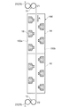
図1は、本実施形態に係るロングスパン延伸法による縦延伸工程を模式的に示す工程断面図である。熱可塑性樹脂フィルム20は、オーブン100と、熱可塑性樹脂フィルム20が導入されるオーブン100の入口付近に設けられた入口側ニップロール10と、オーブン100の熱可塑性樹脂フィルム20の出口付近に設けられた出口側ニップロール12とからなる、縦延伸装置によって、鉛直方向下方(矢印A方向)に移動されながら延伸される。出口側ニップロール12の回転速度を入口側ニップロール10の回転速度よりも早くすることによって、フィルム25を延伸することができる。すなわち、フィルム25のオーブン100出口における移動速度V2は、オーブン100入口における移動速度V1よりも早くなっている。これによって、フィルム20は移動方向すなわち縦方向に延伸される。
FIG. 1 is a process cross-sectional view schematically showing a longitudinal stretching process by a long span stretching method according to the present embodiment. The
オーブン100は、それぞれ独立に温度制御が可能な上流側ゾーン14と下流側ゾーン16とを備える。このように、オーブン100は、フィルムの進行方向と垂直に2〜4ゾーンに区分されていることが好ましい。オーブン100内壁の一方の側面100aには、熱風吹き出し用の複数のノズルが設けられ、他方の側面100bにも、側面100aと同様に複数のノズルが設けられている。ノズル18はその先端部に熱風の吹き出し口を有しており、先端がフィルム25に接触しないような構造となっている。側面100a側のノズル18と側面100b側のノズル18とは鉛直方向に交互に設けられている。オーブン100としては、従来用いられていたエアーフローティング方式の熱風オーブンを、縦向き、すなわちフィルム移動方向が鉛直方向になるように設置して用いることができる。
The
本実施形態の縦延伸工程をさらに詳細に説明する。熱可塑性樹脂フィルム20は、まず上流側ニップロール10に導入される。ニップロール10を通過した熱可塑性樹脂フィルム20は、オーブン100の上流側ゾーン14に入り、鉛直下方(矢印A方向)に移動しながら、複数のノズル18からの熱風によって加熱される。これによって、熱可塑性樹脂フィルム20が縦方向に延伸される。ある程度延伸されたフィルム25は、上流側ゾーン14から下流側ゾーン16に移動し、引き続き加熱されながら縦方向に延伸される。
The longitudinal stretching process of this embodiment will be described in further detail. The
その後、オーブン100の下方から出てニップロール12を経由することによって、延伸フィルム22が得られる。延伸フィルム22は、熱可塑性樹脂フィルム20を縦方向に延伸したものである。
Thereafter, the stretched
フィルム25の延伸温度(すなわち、オーブン100中の雰囲気の温度)は、熱可塑性樹脂フィルム20に含まれる熱可塑性樹脂が非晶性樹脂の場合、当該熱可塑性樹脂の(Tg−20)〜(Tg+30)℃の温度範囲とすることが好ましい。一方、熱可塑性樹脂が結晶性樹脂の場合、当該熱可塑性樹脂の(Tm−40)〜(Tm+10)℃の温度範囲とすることが好ましい。なお、Tgはガラス転移温度を示し、Tmは融点を示す。
When the thermoplastic resin contained in the
本明細書におけるTgは、JIS K7121に従って求められる中間点ガラス転移温度を意味し、具体的には、示差走査熱量計(DSC)などを用い、サンプルを一度融点以上に加熱したのち、所定の速度で−30℃(ポリプロピレン系樹脂の場合)程度まで冷却し、その後、所定の速度で昇温しながら測定して得られるDSC曲線の屈曲点より求められる値である。なお、冷却温度は、樹脂の種類によって適宜変更することができる。 Tg in the present specification means a midpoint glass transition temperature obtained in accordance with JIS K7121, and specifically, after a sample is heated once to a melting point or higher using a differential scanning calorimeter (DSC) or the like, a predetermined speed is obtained. This is a value obtained from the inflection point of the DSC curve obtained by cooling to about −30 ° C. (in the case of polypropylene resin) and then measuring while raising the temperature at a predetermined rate. The cooling temperature can be appropriately changed depending on the type of resin.
本明細書における融点は、JIS K7121に従って求められる、示差走査熱量測定おける融解ピーク温度のことである。結晶性ポリオレフィン系樹脂の融点(Tm)は、通常80〜300℃である。 Melting | fusing point in this specification is a melting peak temperature in a differential scanning calorimetry calculated | required according to JISK7121. The melting point (Tm) of the crystalline polyolefin-based resin is usually 80 to 300 ° C.
縦延伸に用いられるオーブン100の上流側ゾーン14と下流側ゾーン16の温度設定は同じでもよいし、異なってもよい。ただし、それぞれのゾーンの温度(オーブン100中の雰囲気の温度)は、上述の温度範囲を満たすことが好ましい。
The temperature settings of the
縦延伸倍率は、1.01〜3.0倍とすることができる。なお、厚みムラや位相差ムラの発生をより十分に抑制する観点から、縦延伸倍率は、1.05〜2.5倍であることが好ましい。 The longitudinal draw ratio can be 1.01 to 3.0 times. In addition, from the viewpoint of sufficiently suppressing the occurrence of thickness unevenness and retardation unevenness, the longitudinal draw ratio is preferably 1.05 to 2.5 times.
縦延伸に用いられるオーブン100の入口側に設けられるニップロール10の回転速度は、特に限定されず、通常1〜20m/分である。なお、厚みムラや位相差ムラの発生をより十分に抑制する観点から、該回転速度は3〜10m/分であることが好ましい。
The rotational speed of the
縦延伸に用いられるオーブンのフィルム長さ方向の全長は、特に限定はされず、1〜15mとすることができる。厚みムラや位相差ムラの発生をより十分に抑制する観点から、該全長は2〜10mであることが好ましい。 The total length in the film length direction of the oven used for longitudinal stretching is not particularly limited and can be 1 to 15 m. From the viewpoint of sufficiently suppressing the occurrence of thickness unevenness and retardation unevenness, the total length is preferably 2 to 10 m.
オーブン100の各ゾーンに設けられる熱風吹き出し用のノズルの本数は、通常5〜30本とすることができる。厚みムラや位相差ムラの発生をより十分に抑制する観点から、当該ノズルの本数は8〜20本であることが好ましい。
The number of hot air blowing nozzles provided in each zone of the
(横延伸工程)
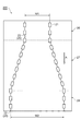
図2は、本実施形態に係るテンター延伸法による横延伸工程を模式的に示す工程図である。横延伸工程は、熱可塑性樹脂フィルム20を横方向(フィルム幅方向)に延伸して、延伸フィルム22を得る工程である。
(Horizontal stretching process)
FIG. 2 is a process diagram schematically showing a transverse stretching process by a tenter stretching method according to the present embodiment. The transverse stretching step is a step of obtaining the stretched
熱可塑性樹脂フィルム20としては、上述の原反フィルムを用いてもよいし、上述の縦延伸工程によって縦延伸されたフィルム25を用いてもよい。
As the
本実施形態の横延伸工程では、熱可塑性樹脂フィルム20をテンター延伸法によって横延伸する。横延伸工程に用いられるオーブン200は、予熱ゾーン26、延伸ゾーン27、及び熱固定ゾーン28を備える。オーブン200は、それぞれのゾーンの温度を独立に調節できるものが好ましい。オーブン200としては、従来のフィルムを水平方向に移動して延伸するテンター延伸法に用いられるオーブンを縦置き、すなわち、フィルムの移動方向が鉛直方向になるように設置したオーブンを用いることができる。
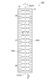
In the lateral stretching step of the present embodiment, the
図3は、本実施形態に係るテンター延伸法による横延伸工程を模式的に示す工程断面図である。オーブン200内の一方の側面200aには、複数のノズル30が設けられている。オーブン200内の他方の側面200bには、複数のノズル32が設けられている。ノズル30とノズル32とは、対向するように設けられている。
FIG. 3 is a process cross-sectional view schematically showing a transverse stretching process by a tenter stretching method according to the present embodiment. A plurality of
予熱ゾーン26,延伸ゾーン27及び熱固定ゾーン28の一方の側面200aに設けられたノズル30は、先端に開口(スリット)を有しており、フィルム25の方向(矢印E方向)に熱風を吹き出すことができる。一方、予熱ゾーン26,延伸ゾーン27及び熱固定ゾーン28の他方の側面に設けられたノズル32は、先端に開口(スリット)を有しており、フィルム25の方向(矢印D方向)に熱風を吹き出すことができる。なお、図3には示していないが、ノズル30及びノズル32は、フィルム25を幅方向に均一に加熱することができるように、図2の紙面に垂直な方向に所定のサイズの奥行きを有している。
The
当該ノズル30,32は、フィルムの幅方向にのびるスリットを熱風の吹き出し口として有する、いわゆるジェットノズルであってもよいし、フィルムと対向する面に複数の例えば円形の開口がフィルムの長手方向及び幅方向に配置されたパンチングノズルであってもよい。
The
オーブン200において、予熱ゾーン26、延伸ゾーン27及び熱固定ゾーン28からなる群より選ばれる少なくとも1つ以上のゾーンにおいて、互いに対向するノズル30とノズル32との間隔L(最短距離)は、150mm以上であることが好ましく、150〜600mmであることがより好ましく、150〜400mmであることがさらに好ましい。このような間隔Lで一対のノズルを対向して配置することによって、各工程におけるフィルムのバタつきを抑制することができる。
In the
また、予熱ゾーン26、延伸ゾーン27及び熱固定ゾーン28に備えられるそれぞれのノズル30,32の吹き出し口における熱風の幅方向(図3の紙面に垂直方向)の最高温度と最低温度との差(ΔT)が、全て2℃以下であることが好ましく、全て1℃以下であることがより好ましい。このように幅方向における温度差が十分に小さい熱風を用いてフィルムを加熱することによって、延伸フィルム22の厚みムラや幅方向の配向性のバラつきを抑制することができる。なお、熱可塑性樹脂フィルム20がポリプロピレン系樹脂からなる場合、用いられる熱風は、フィルムを延伸する温度である80〜170℃の温度範囲で、上記温度差(ΔT)は全て2℃以下であることが好ましく、全て1℃以下であることがより好ましい。
Further, the difference between the maximum temperature and the minimum temperature in the width direction of the hot air (in the direction perpendicular to the paper surface of FIG. 3) at the outlets of the
横延伸工程についてさらに詳細に説明する。まず、幅W1の熱可塑性樹脂フィルム20をオーブン200内に導入し予熱ゾーン26で予熱を行う(図2)。予熱ゾーン26では、熱可塑性樹脂フィルム20を延伸するのに十分な温度にまで熱可塑性樹脂フィルム20を加熱することができる。
The transverse stretching process will be described in more detail. First, the
チャック21で固定された熱可塑性樹脂フィルム20は、チャック21のA方向への移動によって鉛直方向上方から下方に移動して予熱ゾーン26に導入される。熱可塑性樹脂フィルム20は、この予熱ゾーン26で加熱されながら、チャック21の移動に伴いA方向(鉛直方向下方)に移動する。オーブン200内の熱可塑性樹脂フィルム20の移動速度は、1〜100m/分、好ましくは3〜20m/分とすることができる。
The
予熱ゾーン26における予熱温度は、熱可塑性樹脂フィルム20に含まれる熱可塑性樹脂が非晶性樹脂の場合、(Tg−20)〜(Tg+30)℃とすることが好ましい。一方、熱可塑性樹脂フィルム20に含まれる熱可塑性樹脂が結晶性樹脂の場合、(Tm−40)〜(Tm+20)℃とすることが好ましい。なお、本明細書における予熱温度とは、オーブン200の予熱ゾーン26内の雰囲気の温度をいう。
When the thermoplastic resin contained in the
熱可塑性樹脂フィルム20がポリプロピレン系樹脂からなる場合、得られる延伸フィルムの厚みのバラつきや位相差のバラつきを抑制するために、予熱温度は、ポリプロピレン系樹脂の融点をT1とした場合に、(T1−10)〜(T1+10)℃の範囲内とすることが好ましく、(T1−5)〜(T1+5)℃とすることがより好ましい。
When the
予熱ゾーン26において、熱可塑性樹脂フィルム20は、熱可塑性樹脂が非晶性樹脂の場合、延伸ゾーン27に導入される前までに(Tg−20)〜(Tg+30)℃の範囲に加熱されることが好ましい。一方、熱可塑性樹脂フィルム20に含まれる熱可塑性樹脂が結晶性樹脂の場合、(Tm−40)〜(Tm+20)℃の範囲に加熱されることが好ましい。
In the preheating
予熱されたフィルム25は、鉛直方向下方に移動して、予熱ゾーン26から延伸ゾーン27に導入される。延伸ゾーン27では、予熱したフィルム25を、加熱しながら幅方向(矢印A方向に垂直な方向)に横延伸する。延伸温度(延伸ゾーン27内の雰囲気の温度)は予熱温度より低い温度としてもよいし、高い温度としてもよいし、同じ温度としてもよい。
The
熱可塑性樹脂フィルム20がポリプロピレン系樹脂からなる場合、予熱されたフィルム25を予熱温度よりも低い温度で横延伸することにより、熱可塑性樹脂フィルム20を一層均一に延伸することができる。その結果、厚みや位相差の均一性に優れた延伸フィルムが得ることができる。熱可塑性樹脂フィルム20がポリプロピレン系樹脂からなる場合の延伸温度は、予熱温度より5〜20℃低いことが好ましく、7〜15℃低いことがより好ましい。
When the
延伸ゾーン27におけるフィルム25の横延伸は、フィルム25を固定するチャック21を幅方向(矢印A方向とは垂直な方向)に拡げることによって行われる。つまり、チャック21がA方向(鉛直方向下方)に移動しながら、徐々に幅方向(水平方向)に拡がることによって、フィルム25が横方向に引っ張られて横延伸される。これによって、フィルム25は幅W1から幅W2に横延伸される。
The lateral stretching of the
横延伸工程における熱可塑性樹脂フィルム20の横延伸倍率は、2〜10倍であることが好ましい。得られる延伸フィルムの厚みと位相差の均一性を一層向上させる観点から、該横延伸倍率は4〜7倍であることがより好ましい。
It is preferable that the transverse stretch ratio of the
フィルム25は、延伸ゾーン27で延伸された後、矢印A方向(鉛直方向下方)に移動して延伸ゾーン27から熱固定ゾーン28に導入される。
After the
熱固定ゾーン28では、延伸後の横幅W2を保った状態で、所定の温度に加熱することにより、フィルム25の光学的特性(位相差の均一性、光軸の均一性)を安定化させることができる。熱固定温度(熱固定ゾーン28の雰囲気の温度)は、延伸温度より低い温度、高い温度又は同じ温度とすることができる。延伸フィルムの位相差や光軸などの光学的特性の安定性を一層向上させる観点から、熱固定温度は、延伸温度よりも10℃低い温度から延伸温度よりも30℃高い温度までの温度範囲内であることが好ましい。
In the
フィルム25は、熱固定ゾーン28を通過した後、オーブン200から排出される。これによって、横方向(フィルム幅方向)に延伸された延伸フィルム22を得ることができる。
The
このような延伸フィルム22は、加熱延伸時の移動方向を鉛直方向としていることから、横延伸中にフィルムが移動方向以外の方向に垂れることを防止することができる。これによって、厚みムラや位相差ムラが十分に抑制された横延伸フィルムを得ることができる。
Such a stretched
同一熱可塑性樹脂フィルムに対して上述の横延伸と上述の縦延伸とを行うことによって、二軸延伸フィルムを得ることができる。なお、横延伸と縦延伸とを同一オーブン200内で行ってもよい。この場合、鉛直方向上方から下方に移動する熱可塑性樹脂フィルム20を固定するチャック21によって、熱可塑性樹脂フィルムを幅方向(A方向とは垂直な方向)と長手方向(A方向に平行な方向)とに同時又は逐次に引っ張ることによって行うことができる。なお、熱可塑性樹脂フィルム20の長手方向の延伸は、延伸ゾーン27において隣り合うチャック21の間隔を拡げることによって行うことができる。
A biaxially stretched film can be obtained by performing the above-described lateral stretching and the above-described longitudinal stretching on the same thermoplastic resin film. Note that the transverse stretching and the longitudinal stretching may be performed in the
本実施形態の製造方法によって得られる延伸フィルムは、位相差フィルムとして、液晶表示装置の表示部に組み込んで使用することができる。なお、この場合、延伸フィルムに異物などの付着量が少ないことが好ましい。このため、オーブン100及びオーブン200中のクリーン度はクラス1000以下とすることが好ましい。本明細書における「清浄度クラス」とは、米国連邦規格(USA FED.STD)209Dにて規定される清浄度クラスをいうものとし、「清浄度クラス1000」とは、空気中に含まれる粒径0.5μm以下の微粒子が、1立方フィート(1ft3)当たりに1000個を超えない雰囲気であることを意味する。ちなみに、米国連邦規格209Dにて規定される清浄度クラス1000は、JIS B 9920「クリーンルームの空気清浄度の評価方法」にて規定される清浄度クラス6に相当する。
The stretched film obtained by the manufacturing method of this embodiment can be used as a retardation film by being incorporated in a display unit of a liquid crystal display device. In this case, it is preferable that the amount of foreign matters attached to the stretched film is small. For this reason, it is preferable that the cleanliness in the
上記実施形態によって得られる延伸フィルムを液晶表示装置の位相差フィルムとして用いる場合、求められる位相差は、その位相差フィルムが組み込まれる液晶表示装置の種類により異なるが、通常、面内位相差R0は30〜300nmである。垂直配向(VA)モード液晶ディスプレイに使用する場合、優れた視野角特性を確保する観点から、面内位相差R0は40〜70nmであることが好ましく、厚み方向位相差Rthは90〜230nmであることが好ましい。位相差フィルムの厚みは、通常10〜100μmであり、好ましくは10〜60μmである。位相差フィルムを製造する際の縦延伸や横延伸を行う際の延伸倍率や温度等の延伸条件と、製造する位相差フィルムの厚みとを制御することにより、所望の位相差を有する位相差フィルムを得ることができる。 When the stretched film obtained by the above embodiment is used as a retardation film of a liquid crystal display device, the required retardation varies depending on the type of the liquid crystal display device in which the retardation film is incorporated, but usually an in-plane retardation R 0. Is 30-300 nm. When used in a vertical alignment (VA) mode liquid crystal display, the in-plane retardation R 0 is preferably 40 to 70 nm and the thickness direction retardation R th is 90 to 230 nm from the viewpoint of securing excellent viewing angle characteristics. It is preferable that The thickness of the retardation film is usually 10 to 100 μm, preferably 10 to 60 μm. A retardation film having a desired retardation by controlling stretching conditions such as stretching ratio and temperature when performing longitudinal stretching and lateral stretching when producing a retardation film, and the thickness of the retardation film to be produced. Can be obtained.
本実施形態に係る延伸フィルムの製造方法により、例えば、延伸フィルム22の面内(500mm幅×500mm長さの面内)の位相差の最大値と最小値との差が10nm以下で、フィルムの幅方向500mmの光軸を測定した場合に光軸が−1〜+1°以下である、光学的な均一性が高い位相差フィルムを得ることができる。なお、面内位相差は、市販の位相差測定装置を用いて測定することができる。 By the method for producing a stretched film according to this embodiment, for example, the difference between the maximum value and the minimum value of the retardation in the plane of the stretched film 22 (in the plane of 500 mm width × 500 mm length) is 10 nm or less, When the optical axis in the width direction of 500 mm is measured, it is possible to obtain a retardation film having a high optical uniformity and an optical axis of −1 to + 1 ° or less. The in-plane retardation can be measured using a commercially available retardation measuring device.
本実施形態によって得られる延伸フィルムの厚みのバラつきは延伸フィルムの断面を電子顕微鏡で観察することによって評価することができる。本実施形態によって得られる延伸フィルムの厚み精度は、例えば−1〜+1μmとすることができる。 The variation in the thickness of the stretched film obtained by this embodiment can be evaluated by observing the cross section of the stretched film with an electron microscope. The thickness accuracy of the stretched film obtained by this embodiment can be set to, for example, −1 to +1 μm.
この位相差フィルムは、種々の偏光板や液晶層などと積層されて、携帯電話、携帯情報端末(Personal Digital Assistant:PDA)、パソコン、大型テレビ等の液晶表示装置として好ましく用いることができる。 This retardation film is laminated with various polarizing plates, liquid crystal layers, and the like, and can be preferably used as a liquid crystal display device such as a mobile phone, a personal digital assistant (PDA), a personal computer, and a large television.
本実施形態にかかる位相差フィルムを積層する液晶表示装置(LCD)としては、光学補償ベンド(Optically Compensated Bend:OCB)モード、垂直配向(Vertical Alignment:VA)モード、横電界(In−Plane Switching:IPS)モード、薄膜トランジスター(Thin Film Transistor:TFT)モード、ねじれネマティック(Twisted Nematic:TN)モード、超ねじれネマティック(Super Twisted Nematic:STN)モードなど種々のモードの液晶表示装置が挙げられる。 As a liquid crystal display (LCD) on which the retardation film according to the present embodiment is laminated, an optically compensated bend (OCB) mode, a vertical alignment (VA) mode, a lateral electric field (In-Plane Switching): Examples of the liquid crystal display device include various modes such as an IPS mode, a thin film transistor (TFT) mode, a twisted nematic (TN) mode, and a super twisted nematic (Super Twisted Nematic: STN) mode.
本実施形態に係る製造方法によれば、高い軸精度と均一な位相差を有する、光学的均一性に優れた熱可塑性樹脂製の延伸フィルムを得ることができる。この延伸フィルムは、位相差フィルムとして、大型液晶テレビなどの大画面の液晶ディスプレイに用いられた場合でも、光学的な不均一性に由来する位相差や光軸のムラが殆どなく、視野角依存性を改善する効果を有するものである。また、軸精度が高く、均一な位相差を有する位相差フィルムを備える上述の液晶表示装置は、視野角特性及び耐久性に優れるものである。 According to the manufacturing method according to the present embodiment, it is possible to obtain a stretched film made of a thermoplastic resin having high axial accuracy and uniform phase difference and excellent in optical uniformity. Even when this stretched film is used as a retardation film in a large-screen liquid crystal display such as a large-sized liquid crystal television, there is almost no retardation or optical axis unevenness due to optical nonuniformity, and it depends on the viewing angle. It has the effect of improving the property. In addition, the above-described liquid crystal display device including a retardation film having high axial accuracy and a uniform retardation has excellent viewing angle characteristics and durability.
以上、本発明の好適な実施形態について説明したが、本発明は上記実施形態に何ら限定されるものではない。 The preferred embodiment of the present invention has been described above, but the present invention is not limited to the above embodiment.
例えば、本実施形態では、縦延伸工程及び横延伸工程においてフィルムの移動方向を鉛直方向上方から下方に向かう方向としたが、該移動方向を鉛直方向下方から上方に向かう方向としても、本発明の効果を得ることができる。また、横延伸工程を先に行い、その後縦延伸工程を行って二軸延伸フィルムを製造することも可能である。 For example, in this embodiment, in the longitudinal stretching step and the lateral stretching step, the moving direction of the film is a direction from the vertical direction upward to the downward direction, but the moving direction may be a direction from the vertical direction downward to the upward direction. An effect can be obtained. Moreover, it is also possible to manufacture a biaxially stretched film by first performing a horizontal stretching process and then performing a vertical stretching process.
10,12…ニップロール、14…上流側ゾーン、16…下流側ゾーン、18,30,32…ノズル、20…熱可塑性樹脂フィルム、21…チャック、22…延伸フィルム、25…フィルム、26…予熱ゾーン、27…延伸ゾーン、28…熱固定ゾーン、100,200…オーブン、100a,100b,200a,200b…側面。
DESCRIPTION OF
Claims (5)
前記縦延伸工程及び前記横延伸工程の少なくとも一方における前記移動方向が、略鉛直方向である延伸フィルムの製造方法。 A longitudinal stretching process for stretching a plate-shaped thermoplastic resin film moving in the oven in a longitudinal direction parallel to the moving direction, and a plate-shaped thermoplastic resin film moving in the oven in a width direction perpendicular to the moving direction. A method for producing a stretched film having at least one of transverse stretching steps to stretch,
A method for producing a stretched film, wherein the moving direction in at least one of the longitudinal stretching step and the lateral stretching step is a substantially vertical direction.
The stretched film according to any one of claims 1 to 4, wherein the moving direction in at least one of the longitudinal stretching step and the lateral stretching step is a direction from substantially upward in the vertical direction to downward. Manufacturing method.
Priority Applications (1)
| Application Number | Priority Date | Filing Date | Title |
|---|---|---|---|
| JP2007245713A JP2009073109A (en) | 2007-09-21 | 2007-09-21 | Manufacturing method of stretched film |
Applications Claiming Priority (1)
| Application Number | Priority Date | Filing Date | Title |
|---|---|---|---|
| JP2007245713A JP2009073109A (en) | 2007-09-21 | 2007-09-21 | Manufacturing method of stretched film |
Publications (2)
| Publication Number | Publication Date |
|---|---|
| JP2009073109A true JP2009073109A (en) | 2009-04-09 |
| JP2009073109A5 JP2009073109A5 (en) | 2011-01-20 |
Family
ID=40608575
Family Applications (1)
| Application Number | Title | Priority Date | Filing Date |
|---|---|---|---|
| JP2007245713A Pending JP2009073109A (en) | 2007-09-21 | 2007-09-21 | Manufacturing method of stretched film |
Country Status (1)
| Country | Link |
|---|---|
| JP (1) | JP2009073109A (en) |
Cited By (1)
| Publication number | Priority date | Publication date | Assignee | Title |
|---|---|---|---|---|
| WO2013080721A1 (en) * | 2011-12-01 | 2013-06-06 | 株式会社康井精機 | Annealing method and annealing device |
Citations (8)
| Publication number | Priority date | Publication date | Assignee | Title |
|---|---|---|---|---|
| JPS63197628A (en) * | 1987-02-13 | 1988-08-16 | Toshio Kunugi | Production of high strength polyimide film |
| JPH02175229A (en) * | 1988-12-28 | 1990-07-06 | Toyobo Co Ltd | Lateral stretching device of film |
| JP2002052493A (en) * | 2000-08-09 | 2002-02-19 | Kuraray Co Ltd | Manufacturing method for ethylene-vinyl alcohol copolymer resin film |
| JP2002292729A (en) * | 2001-03-29 | 2002-10-09 | Sekisui Chem Co Ltd | Thermoplastic resin foamed sheet, its manufacturing method and manufacturing method for warmth-keeping tube |
| JP2003026318A (en) * | 2001-07-13 | 2003-01-29 | Daikin Ind Ltd | Conveying device and chain used therefor |
| JP2006281628A (en) * | 2005-03-31 | 2006-10-19 | Nippon Zeon Co Ltd | Method for producing oriented film and phase difference film |
| JP2007210306A (en) * | 2006-02-13 | 2007-08-23 | Nippon Zeon Co Ltd | Simultaneous biaxial drawing machine, and manufacturing method for optical film |
| JP2009063982A (en) * | 2006-12-28 | 2009-03-26 | Nitto Denko Corp | Process for producing polarizer, polarizer, polarizing plate, optical film, process for producing composite polarizing plate, composite polarizing plate and image display device |
-
2007
- 2007-09-21 JP JP2007245713A patent/JP2009073109A/en active Pending
Patent Citations (9)
| Publication number | Priority date | Publication date | Assignee | Title |
|---|---|---|---|---|
| JPS63197628A (en) * | 1987-02-13 | 1988-08-16 | Toshio Kunugi | Production of high strength polyimide film |
| JPH02175229A (en) * | 1988-12-28 | 1990-07-06 | Toyobo Co Ltd | Lateral stretching device of film |
| JP2606345B2 (en) * | 1988-12-28 | 1997-04-30 | 東洋紡績株式会社 | Film stretching equipment |
| JP2002052493A (en) * | 2000-08-09 | 2002-02-19 | Kuraray Co Ltd | Manufacturing method for ethylene-vinyl alcohol copolymer resin film |
| JP2002292729A (en) * | 2001-03-29 | 2002-10-09 | Sekisui Chem Co Ltd | Thermoplastic resin foamed sheet, its manufacturing method and manufacturing method for warmth-keeping tube |
| JP2003026318A (en) * | 2001-07-13 | 2003-01-29 | Daikin Ind Ltd | Conveying device and chain used therefor |
| JP2006281628A (en) * | 2005-03-31 | 2006-10-19 | Nippon Zeon Co Ltd | Method for producing oriented film and phase difference film |
| JP2007210306A (en) * | 2006-02-13 | 2007-08-23 | Nippon Zeon Co Ltd | Simultaneous biaxial drawing machine, and manufacturing method for optical film |
| JP2009063982A (en) * | 2006-12-28 | 2009-03-26 | Nitto Denko Corp | Process for producing polarizer, polarizer, polarizing plate, optical film, process for producing composite polarizing plate, composite polarizing plate and image display device |
Cited By (2)
| Publication number | Priority date | Publication date | Assignee | Title |
|---|---|---|---|---|
| WO2013080721A1 (en) * | 2011-12-01 | 2013-06-06 | 株式会社康井精機 | Annealing method and annealing device |
| JP2013111970A (en) * | 2011-12-01 | 2013-06-10 | Yasui Seiki:Kk | Annealing method and annealing apparatus |
Similar Documents
| Publication | Publication Date | Title |
|---|---|---|
| JP2009093168A (en) | Method for producing retardation film | |
| JP4973264B2 (en) | Retardation film and method for producing the same | |
| US20100258960A1 (en) | Process for producing optical film made of thermoplastic resin | |
| TWI410322B (en) | Phase difference film and its manufacturing method | |
| TWI408047B (en) | Production method of phase difference film made of | |
| CN101802060B (en) | Optical film | |
| US20100149470A1 (en) | Precursor film for retardation films, retardation film, and liquid crystal display device | |
| TW201249969A (en) | Manufacturing method and apparatus of crystalline resin membrane | |
| TW201003249A (en) | Retardation film with pressure-sensitive adhesive layer and elliptical polarizer and liquid-crystal display both employing the same | |
| TW200932495A (en) | Manufacturing method of raw film for retardation film made of polypropyrene resin | |
| JP4917508B2 (en) | Method for producing retardation film | |
| JP2009073109A (en) | Manufacturing method of stretched film | |
| JP5097066B2 (en) | Method for producing crystalline polyolefin resin film | |
| TWI657273B (en) | Manufacturing method of thermoplastic resin film | |
| JP2012081676A (en) | Method of manufacturing biaxially oriented film, biaxially oriented film, and liquid crystal display device equipped with biaxially oriented film | |
| JP2013228712A (en) | Method for manufacturing polypropylene resin retardation film | |
| JP2009090657A (en) | Manufacturing method of crystalline polyolefin resin film | |
| TW201012834A (en) | Optic thin film | |
| JP2014029364A (en) | Laminate roll | |
| JP2017196815A (en) | Method for producing thermoplastic resin stretched sheet | |
| JP2017196816A (en) | Method for producing thermoplastic resin stretched sheet |
Legal Events
| Date | Code | Title | Description |
|---|---|---|---|
| A621 | Written request for application examination |
Free format text: JAPANESE INTERMEDIATE CODE: A621 Effective date: 20100913 |
|
| A521 | Written amendment |
Free format text: JAPANESE INTERMEDIATE CODE: A523 Effective date: 20101129 |
|
| A977 | Report on retrieval |
Free format text: JAPANESE INTERMEDIATE CODE: A971007 Effective date: 20120118 |
|
| A131 | Notification of reasons for refusal |
Free format text: JAPANESE INTERMEDIATE CODE: A131 Effective date: 20120124 |
|
| A02 | Decision of refusal |
Free format text: JAPANESE INTERMEDIATE CODE: A02 Effective date: 20120522 |