JP2009070530A - Loading case for electronic equipment - Google Patents
Loading case for electronic equipment Download PDFInfo
- Publication number
- JP2009070530A JP2009070530A JP2007241037A JP2007241037A JP2009070530A JP 2009070530 A JP2009070530 A JP 2009070530A JP 2007241037 A JP2007241037 A JP 2007241037A JP 2007241037 A JP2007241037 A JP 2007241037A JP 2009070530 A JP2009070530 A JP 2009070530A
- Authority
- JP
- Japan
- Prior art keywords
- hard disk
- vibration
- disk device
- connector
- damper
- Prior art date
- Legal status (The legal status is an assumption and is not a legal conclusion. Google has not performed a legal analysis and makes no representation as to the accuracy of the status listed.)
- Pending
Links
Images


Abstract
Description
本発明は、電子機器の搭載筐体に関し、さらに詳しくは、ダンパおよび制振部材によって、搭載筐体外部からの電子機器への振動を制振する構造を有する電子機器の搭載筐体に関する。 The present invention relates to a mounting case for an electronic device, and more particularly, to a mounting case for an electronic device having a structure in which vibration from the outside of the mounting case to the electronic device is suppressed by a damper and a damping member.
従来から、精密な電子機器を振動や衝撃から保護して使用するための技術が開発されている。例えば、上記のような精密な電子機器として、記録容量が大きく、高速に大量のデータを読み書きすることのできる記録再生装置であるハードディスク装置を振動や衝撃から保護して使用するための需要が高まっている。 2. Description of the Related Art Conventionally, techniques for protecting and using precision electronic devices from vibration and impact have been developed. For example, as a precision electronic device as described above, there is an increasing demand for protecting a hard disk device, which is a recording / reproducing device capable of reading and writing a large amount of data at high speed, while protecting it from vibrations and shocks. ing.
ハードディスク装置は、大容量の記録容量を実現するために、極めて高密度に情報を記録・再生する記録再生手段である磁気ヘッドを備えている。例えばハードディスクでは、円盤状のディスクに微細な記録領域を形成し、上記の磁気ヘッドをディスク上の記録領域に対して高精度に位置決めして情報を読み書きすることによって高密度な情報を記録し、再生している。また、大容量を実現するために、磁気ヘッドとディスクとは非常に小さな間隔を保持した状態で情報を記録再生している。つまり、ハードディスク装置などの大容量の記録再生装置では、動作中の磁気ヘッドの位置の再現性がきわめて重要であり、高精度の位置決め精度が要求されている。 In order to realize a large recording capacity, the hard disk device includes a magnetic head which is a recording / reproducing means for recording / reproducing information at an extremely high density. For example, in a hard disk, a high-density information is recorded by forming a fine recording area on a disk-shaped disk, positioning the magnetic head with respect to the recording area on the disk with high accuracy, and reading and writing information, Playing. In order to realize a large capacity, information is recorded / reproduced with a very small distance between the magnetic head and the disk. In other words, in a large-capacity recording / reproducing apparatus such as a hard disk device, the reproducibility of the position of the magnetic head in operation is extremely important, and high positioning accuracy is required.
このため、ハードディスク装置などは外部からの振動や衝撃に弱いことが知られている。外部から振動や衝撃が加わると、磁気ヘッドの位置にぶれが生じ、正確な記録再生が行えなくなるためである。また、振動や衝撃が大きくなると、ディスク上に磁気ヘッドが接触し、磁気ヘッドやディスクなどを物理的に損傷し、記録再生が行えないようになる場合がある。そのため、今日では記録再生を行わない場合には、磁気ヘッドがディスクから離れた位置に移動するような機構も実現されている。また、ハードディスク装置が落下の重力や衝撃を感知した場合に、磁気ヘッドがディスクから離れた位置に移動するような機構も実現されている。 For this reason, it is known that hard disk drives are vulnerable to external vibrations and shocks. This is because if an external vibration or impact is applied, the position of the magnetic head is shaken and accurate recording / reproduction cannot be performed. In addition, when vibration or impact increases, the magnetic head may come into contact with the disk, physically damaging the magnetic head or disk, and recording / reproducing may not be performed. For this reason, a mechanism has been realized in which the magnetic head moves to a position away from the disk when recording and reproduction are not performed today. Also, a mechanism has been realized in which the magnetic head moves to a position away from the disk when the hard disk device senses falling gravity or shock.
また、ハードディスク装置の内部に生じる振動の影響を低減するための技術として、電気配線をFPC(Flexible Printed Circuit)によって接続し、さらにFPCに空洞(スリット)を設けることによって特定周波数の固有振動数を低減する技術(特許文献1)が知られている。特許文献1では、ハードディスクドライブ内に物理的に生じる振動エネルギーの特定周波数での固有振動数をFPCに設けたスリットの形状によって制御し、ハードディスク装置の動作を安定させる技術を開示している。
In addition, as a technique for reducing the influence of vibration generated inside the hard disk device, the electrical frequency is connected to the FPC (Flexible Printed Circuit), and a cavity (slit) is provided in the FPC to reduce the natural frequency of a specific frequency. A technique for reducing this is known (Patent Document 1).
一方、ハードディスク装置はその動作時において振動などに弱いのであるが、その大容量の記録容量を持ち運ぶ用途としても重宝されている。例えばノートパソコンなどの持ち運び型のコンピュータの記録再生装置や、車載型道路ナビゲーションシステムの記録再生装置など、現在では大容量の電子情報を持ち運ぶ手段として広く用いられている。このようにハードディスク装置を振動の発生する環境で使用する場合には、ハードディスク装置の周囲に振動を吸収するためのダンパを設け、ハードディスク装置自体に外部の振動が伝わりにくくする技術などが知られている。 On the other hand, the hard disk device is susceptible to vibration during operation, but is also useful for carrying a large recording capacity. For example, a portable computer recording / reproducing device such as a notebook personal computer or a vehicle-mounted road navigation system recording / reproducing device is now widely used as a means for carrying large amounts of electronic information. In this way, when using the hard disk device in an environment in which vibration is generated, a technique for providing a damper for absorbing vibration around the hard disk device to make it difficult for external vibration to be transmitted to the hard disk device itself is known. Yes.
また、上記のようなハードディスク装置を従来の記録媒体、例えばコンパクトディスク(CD:Compact Disk)やDVD(Digital Versatile Disk)のように取り替え可能な大容量記録媒体として用いることも行われている。これは、例えば特許文献2に開示されている情報記憶装置のように、ハードディスク装置を備えるHDDユニットが着脱機構を備えており、ハウジングに着脱されるなどの方法によって実現されている。また特許文献3に開示されているハードディスク装置のように、着脱可能なHDDユニットが振動減衰手段を備えており、大容量の電子情報を着脱可能に持ち運ぶ技術も知られている。 In addition, the hard disk device as described above is also used as a replaceable large-capacity recording medium such as a conventional recording medium such as a compact disk (CD) or a DVD (Digital Versatile Disk). This is realized by a method in which an HDD unit including a hard disk device includes an attachment / detachment mechanism and is attached to / detached from a housing as in the information storage device disclosed in Patent Document 2, for example. In addition, as in the hard disk device disclosed in Patent Document 3, a detachable HDD unit includes vibration damping means, and a technique for carrying a large amount of electronic information in a detachable manner is also known.
このような技術を用いることによって、CDやDVDでは実現が困難である大容量の記録容量を自由に着脱して取替え、高速に読み書きする記録再生装置が実現されている。
しかしながら、上記従来の構成では、内蔵する電子機器に生じた振動を効果的に収束させ、制振することが難しいという問題点を有している。 However, the above-described conventional configuration has a problem that it is difficult to effectively converge and suppress vibration generated in the built-in electronic device.
従来は、電子機器ユニット外に生じた振動が内蔵する電子機器に伝わり、電子機器が振動した場合には、電子機器ユニットと電子機器の搭載筐体との間に設けられるダンパなどの振動減衰手段によって電子機器の振動を減衰していた。 Conventionally, vibration generated outside the electronic device unit is transmitted to the built-in electronic device, and when the electronic device vibrates, vibration damping means such as a damper provided between the electronic device unit and the mounting case of the electronic device. This attenuated the vibration of the electronic equipment.
しかしながら振動減衰手段での振動の減衰を早く収束させようとすると、振動減衰手段の弾性を大きくする必要があり、振動を効果的に和らげる効果が得られにくかった。また、振動を和らげるために振動減衰手段の弾性を小さくすると、振動がなかなか減衰しなかった。そのため、上記振動減衰手段を多数用いる方法も行われていた。 However, in order to quickly converge the vibration attenuation by the vibration attenuating means, it is necessary to increase the elasticity of the vibration attenuating means, and it is difficult to obtain an effect of effectively reducing the vibration. In addition, when the elasticity of the vibration damping means was reduced to reduce the vibration, the vibration was not easily attenuated. For this reason, a method using a large number of vibration damping means has also been performed.
図5は、特許文献3に開示されたHDDユニット500の平面図である。図5に記載するHDDユニット500では、ハードディスク装置560の底面に設けられた振動減衰手段541によってHDDユニット500に設置されているとともに、防振ダンパ542によってシャーシ510に保持されている構成であり、多数の振動減衰手段を用いる方法について開示している。
FIG. 5 is a plan view of the
図6は、特許文献3に開示されたHDDユニットを横から見た場合の平面図である。図6に記載するHDDユニット500では、ハードディスク装置560がシャーシ510の底面に設けられた振動減衰手段541によって設置されている。また紙面の手前側及び向こう側(図5及び図6に記載するx軸の方向)に防振ダンパ542が設けられている。
FIG. 6 is a plan view of the HDD unit disclosed in Patent Document 3 when viewed from the side. In the
このとき、振動減衰手段541がハードディスク装置560の底面に設けられており、防振ダンパ542がハードディスク装置560の対向する側面に設けられているので、振動減衰手段541及び防振ダンパ542のそれぞれの振動減衰作用が十分に発揮されにくいという問題があった。
At this time, since the vibration damping means 541 is provided on the bottom surface of the
例えば、HDDユニット500が上下方向(図5及び図6に記載するz軸の方向)に動くと、ハードディスク装置560は上下方向に揺すられると共に振動減衰手段541及び防振ダンパ542の振動減衰効果によって動きが抑制される。
For example, when the
一方、左右方向または前後方向(それぞれ図5及び図6に記載するx軸の方向及びy軸の方向)に揺すられた場合、ハードディスク装置560は振動減衰手段541を軸として左右または前後に振れながら揺れ動こうとすると同時に、防振ダンパ542の振動減衰効果によって動きが抑制されることになる。このとき、HDDユニットの左右方向または前後方向では、ハードディスク装置560の底面に設けられている振動減衰手段541によって内蔵されているハードディスク装置560の動きが制限されていた。
On the other hand, when shaken in the left-right direction or the front-rear direction (the x-axis direction and the y-axis direction shown in FIGS. 5 and 6, respectively), the
また、ハードディスク装置560の側面に振動減衰手段が設けられている構成でも、上述のように振動減衰手段の弾性だけで振動を制御することが難しかった。
Even in the configuration in which the vibration damping means is provided on the side surface of the
本発明は、上記従来の問題点に鑑みなされたものであって、その目的は、内蔵する電子機器に生じた振動を効果的に抑制または緩衝する構造を有する電子機器の搭載筐体を提供することにある。 The present invention has been made in view of the above-described conventional problems, and an object thereof is to provide a mounting case for an electronic device having a structure that effectively suppresses or cushions vibration generated in the built-in electronic device. There is.
本発明の電子機器の搭載筐体は、上記課題を解決するために、電子機器の搭載筐体であって、上記電子機器は、対向する一対の側面に、弾性を有する複数個の振動減衰手段を備えており、上記搭載筐体は、上記電子機器の上記振動減衰手段が設けられていない側面と対向する面に、制振手段を備えていることを特徴としている。 In order to solve the above problems, an electronic device mounting housing according to the present invention is an electronic device mounting housing, and the electronic device has a plurality of vibration damping means having elasticity on a pair of opposing side surfaces. The mounting housing includes a damping means on a surface facing the side surface of the electronic device where the vibration damping means is not provided.
上記の構成によれば、電子機器は、その一対の側面に、弾性を有する複数個の振動減衰手段を備えることにより、搭載筐体に設置されている。弾性を有する振動減衰手段は、搭載筐体に外部から加えられた振動を和らげつつ、搭載筐体内部に搭載された電子機器の揺動する振動周波数を下げることができる。一般的に振動周波数を下げると、揺動の振幅が大きくなるが、本発明では、さらに振動減衰手段が設けられていない側面に対する搭載筐体の側面に制振手段が設けられており、電子機器が制振部材に接触することによって揺動を効果的に抑制することができる。また、制振手段によって、電子機器が搭載筐体に直接接触することを効果的に防ぐことができる。 According to said structure, the electronic device is installed in the mounting housing | casing by providing the some vibration damping means which has elasticity in a pair of side surface. The elastic vibration attenuating means can reduce the vibration frequency of the electronic device mounted inside the mounting casing while reducing the vibration applied to the mounting casing from the outside. Generally, when the vibration frequency is lowered, the amplitude of the swing increases, but in the present invention, the vibration control means is provided on the side surface of the mounting housing with respect to the side surface on which the vibration damping means is not provided. Can be effectively suppressed by contacting the damping member. Further, the vibration damping means can effectively prevent the electronic device from coming into direct contact with the mounting housing.
本発明の実施の形態について図1〜図3に基づいて説明すれば、以下の通りである。 The embodiment of the present invention will be described below with reference to FIGS.
以下の実施の形態としては、内蔵する電子機器の一実施形態としてハードディスク装置を用いる場合について記載するが、内蔵する電子機器は外部からの振動を伝達することが好ましくない電子機器全般について適用することができる。 In the following embodiments, a case where a hard disk device is used as an embodiment of the built-in electronic device will be described. However, the built-in electronic device is applicable to all electronic devices in which it is not preferable to transmit external vibration. Can do.
図1(a)〜(d)は、本実施の形態のHDDユニット100を示す平面図及び断面図である。本実施の形態では、HDDユニット100が直方体形状である場合について記載するが、HDDユニットは他の形状で形成することも可能である。
1A to 1D are a plan view and a cross-sectional view showing an
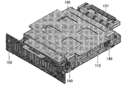
図1(a)は本実施の形態のHDDユニット100を上方から見た平面図であり、HDDユニット100を装着する電子機器装着装置200と共に記載されている。また図1(b)は、本実施の形態のHDDユニット100の側面図である。また図1(c)は、図1(a)のA−A’断面図であり、図1(d)は本実施の形態のHDDユニット100を正面から見た平面図である。また、図2は、本実施の形態のHDDユニット100を示す斜視図である。
FIG. 1A is a plan view of the
本実施の形態の電子機器装着装置200は、本実施の形態のHDDユニット100を装着する装置であり、本実施の形態のHDDユニット100を電気的に接続するためのコネクタ230を備えている。コネクタ230は、後述するコネクタ接続部130に電気的に接続するコネクタであり、周知の構造のコネクタを用いることができる。
The electronic
本実施の形態のHDDユニット100は、例えば大容量の記録容量を持ち運ぶ記録媒体として用いることができる。そのため、電子機器装着装置200はその記録媒体としてのHDDユニット100を取り付け、取り外しできる装置であればよい。このような装置は、例えば設置型、またはノートパソコンなどの持ち運び型のコンピュータの外部記録再生装置や、車載型道路ナビゲーションシステムの記録再生装置などの周知の装置に用いることができる。またHDDユニット100と電子機器装着装置200との接続方法もネジ止めなどの周知の方法を用いて接続、固定を行うことができる。
The
本実施の形態のHDDユニット100は、シャーシ110、FPCハーネス部120、コネクタ接続部130、ダンパ140、フロントグリル150、及びハードディスク装置160を備えている。
The
シャーシ110は、コネクタ接続部130及びフロントグリル150とともに本実施の形態のHDDユニット100の基本骨格構造を形成している。シャーシ110は、周知のハードディスクマウンタなどと同様に形成することができる。例えば鉄やアルミなどを含有する合金で形成しても良い。またその外形などは、後述するように用いるハードディスク装置160などに合わせて形成しても良いし、HDDユニット100を装着する電子機器装着装置200の形状に合わせて形成しても良い。
The
また本実施の形態のHDDユニット100は、衝撃吸収部111を備えている。衝撃吸収部111は、シャーシ110上に設けられた衝撃吸収フレーム112の表面に設けられており、ハードディスク装置160がシャーシ110に直接接触しないように形成されている。衝撃吸収部111及び衝撃吸収フレーム112を設ける位置については詳しくは後述する。
The
コネクタ接続部130は、本実施の形態のHDDユニット100を電子機器装着装置200に電気的に接続するためのコネクタ131(搭載筐体コネクタ)を備えている。本実施の形態のコネクタ131は、フィルム状に形成されたFPC(Flexible Printed Circuit)によって形成されたFPCハーネス部120に接続している。FPCハーネス部120についての詳細は後述するが、本実施の形態のコネクタ131では、FPCハーネス部120のフィルム状のFPCが平面的にコネクタ131に接続している。また本実施の形態のコネクタ131は、平面形状の基板として形成されている。
The
尚、本実施の形態では、コネクタ131の表面と、コネクタ131及びFPCハーネス部120の接合面とは、ハードディスク装置160のディスク面に平行である。
In the present embodiment, the surface of the
コネクタ131はまた、FPCハーネス部120を介してハードディスク装置160に設けられているコネクタ161(電子機器コネクタ)に電気的に接続している。
The
フロントグリル150は、HDDユニット100においてコネクタ接続部130が設けられている側に対向するシャーシ110の側面に設けられている。本実施の形態のHDDユニット100において、フロントグリル150にはシャーシ110内部に設けられるハードディスク装置160に冷却用の空気を送ることのできる換気スリット151が設けられている。
The
本実施の形態のHDDユニット100は、現在市場に流通している形状のハードディスク装置を用いることが可能である。また、専用に製作されたハードディスク装置を用いることもできる。上記のシャーシ110は、これらのハードディスク装置を後述するダンパ140を介して固定することができる形状であればよく、周知の方法で形成することができる。
The
本実施の形態のHDDユニット100に装着されるハードディスク装置160は、例えば現在市場に流通している2.5インチ型、3.5インチ型などの規格品を装着することも可能であるし、さらに専用に製造されたハードディスク装置などを自由に装着することができる。
The
本実施の形態のHDDユニット100では、ハードディスク装置160に設けられているコネクタ161とコネクタ接続部130に設けられているコネクタ131とがFPCハーネス部120によって物理的に接続されているとともに、電気的に接続されている。本実施の形態のHDDユニット100では、FPCハーネス部120はフィルム状に形成されたFPC(Flexible Printed Circuit)によって形成されている。FPCは周知の方法で形成されている部材を用いることができる。
In the
本実施の形態のFPCハーネス部120は、コネクタ161とコネクタ131との間に1個または複数個のスリット121を備えている。このスリット121は、例えばコネクタ161からコネクタ131に延びる方向に沿って設けられていても良い。このようにFPCハーネス部120に形成されているスリット121によって、FPCハーネス部120が有する弾性および固有振動数を適宜設定することができる。すなわち、FPCハーネス部120が接しているハードディスク装置160の振動を抑えることができる弾性および固有振動数となるように、スリット121を形成すればよい。
The
そして、本実施の形態のFPCハーネス部120は、十分な長さでハードディスク装置160及びコネクタ131を接続しており、FPCハーネス部120がハードディスク装置160とコネクタ131との間で緩やかに湾曲して接続されていることが好ましい。例えばコネクタ161とコネクタ131との間であり、コネクタ131にFPCハーネス部120が差し込まれる方向に対して波型に湾曲した形状で接続されていると共にコネクタ131の表面に対しても波型に湾曲した形状で接続されていてもよい。本実施の形態のFPCハーネス部120はこのようにコネクタ161とコネクタ131との間が接続されているため、外部からの振動や衝撃によってFPCハーネス部120がハードディスク装置160を物理的に押したり、引っ張ったりする作用を抑えることができる。
The
尚、FPCハーネス部120は、コネクタ131にFPCハーネス部120が差し込まれる方向に沿って延設されていても良いし、コネクタ131にFPCハーネス部120が差し込まれる方向と異なる方向に向かって延設されていても良い。FPCハーネス部120は、コネクタ161とコネクタ131との位置関係に依存して延設することができる。
The
また、本実施の形態のダンパ140は、シャーシ110とハードディスク装置160とを物理的に接続している部材である。本実施の形態のHDDユニット100では、ダンパ140はハードディスク装置160の側面に形成されている。
In addition, the
図3は、本実施の形態のHDDユニット100を上方から見た平面図であり、図1(a)に示すシャーシ110の一部を透視するように記載している。本実施の形態のダンパ140は、図3に記載するように、ハードディスク装置160のディスク面に対して垂直なハードディスク装置160の側面であって、コネクタ131及びフロントグリル150に対向しない側面にそれぞれ2個ずつ、合計4個設けられている。つまり、ハードディスク装置160の対向する一対の側面にそれぞれ2個ずつ、合計4個のダンパ140が設けられている。
FIG. 3 is a plan view of the
これらのダンパ140は、ハードディスク装置160の上記の側面の任意の位置に設けてもよいが、例えばハードディスク装置160が固定用として備えている図示しない取り付けネジ部に固定されていても良い。またこれらの4個のダンパ140は、ハードディスク装置160の側面の対称となる位置に設けても良い。すなわち、一方の側面に設けられた2個のダンパ140と他方の側面に設けられた2個のダンパ140とが、ハードディスク装置160の中心に対して対称となるように設けてもよい。このようにハードディスク装置160がシャーシ110に設置されることによって、安定して設置することができる。
These
尚、ダンパ140はハードディスク装置160にネジ止めなどの周知の方法で固定することができる。
The
本実施の形態のダンパ140は、外部からシャーシ110に与えられた振動を吸収、緩和する部材であり、弾性を有する部材で形成されている。本実施の形態のHDDユニット100では、衝撃などによって外部から加えられた振動を振幅が大きい揺動として振動する部材であることが好ましい。同じエネルギーの衝撃を外部から受けた場合、本実施の形態のダンパ140のように大きな振幅の揺動として振動する部材では、振動の周期が長くなる(固有振動数が小さくなる)傾向がある。このような部材としては、例えば衝撃などの振動を和らげる効果の高い弾性部材などが適している。例えばこのような部材はシリコンゴムなどの弾性部材で形成されていても良いし、オイルなどの流体で支えられている弾性部材で形成されていても良い。このようなダンパとして、例えばPioneer material Precision Techが硬度及び材質としてIIR10°として表記する商品として供給しているダンパなどを用いることができる。
The
ここで、衝撃吸収部111及び衝撃吸収フレーム112を設ける位置について詳しく記載する。上述のように、ハードディスク装置160がハードディスク装置160のディスク面に対して垂直なハードディスク装置160の側面に設けられたダンパ140によって保持されている。そのため、ハードディスク装置160の側面にダンパ140が設けられていない側面では、ハードディスク装置160とシャーシ110とが接触する可能性がある。
Here, the positions where the
そのため、衝撃吸収部111及び衝撃吸収部111を設ける衝撃吸収フレーム112は、コネクタ接続部130が設けられている側及びフロントグリル150が設けられている側のハードディスク装置160の側面を保護するように設けられることが好ましい。
Therefore, the
本実施の形態では、図1(c)及び図3に示すように、衝撃吸収フレーム112はコネクタ接続部130が設けられている側及びフロントグリル150が設けられている側に面したハードディスク装置160の側面から4mm離れた位置に、前記側面に平行な面としてシャーシ底面から垂直に延設して形成されている。そして、衝撃吸収フレーム112の4箇所に、ハードディスク装置160の側面であり、角に近い位置に対向する位置に、衝撃吸収部111が形成されている。
In the present embodiment, as shown in FIGS. 1C and 3, the
衝撃吸収部111は、シリコンゴムなどの弾性部材で形成され、例えば株式会社ジェルテック社が供給しているθ7、厚み2mmの部材などの衝撃吸収性に優れる部材を用いることができる。
The
また、衝撃吸収部111は、衝撃吸収部111とハードディスク装置160とが振動発生時に緩やかに接触する距離になるように設けられることが好ましい。例えば衝撃吸収部111とハードディスク装置160とが2mmの間隔を開けて配置されることが好ましい。
Moreover, it is preferable that the
このように形成されたHDDユニット100に振動が作用した場合の動作について説明する。
An operation when vibration is applied to the
本実施の形態のHDDユニット100では、外部からシャーシ110に与えられた振動及び衝撃が大きな振幅の揺動に変換するダンパ140によって振動を減衰するとともに、シャーシ110から延設する衝撃吸収部111にハードディスク装置160が接触することによって外部からシャーシ110に与えられた振動が制振される。
In the
外部からシャーシ110に振動が与えられると、ダンパ140は振幅の大きい、そして振動の周期の長い振動としてハードディスク装置160を揺らす。例えば上記のIIR10°のダンパと、これよりも硬いIIR30°のダンパを用いて同様に衝撃を与えると、IIR10°のダンパでは振幅4.36mm、振動周波数17.1Hzで振動したが、IIR30°のダンパでは振幅0.36mm、振動周波数48.2Hzで振動した。つまり弾性の小さいIIR10°のダンパでは外部からシャーシ110に与えられた振動が大きな振幅の揺動に変換されていることがわかる。
When vibration is applied to the
このような弾性の小さい部材をダンパとして用いると、振動を和らげる効果が高くなる一方、振動がなかなか減衰しないという問題が生じていた。 When such a low-elasticity member is used as a damper, there is a problem that vibrations are not easily attenuated while the effect of reducing vibrations is enhanced.
本実施の形態のHDDユニット100では、ダンパ140によって大きな振幅の揺動に変換された外部からの衝撃によるエネルギーを効果的に減衰させるために、ハードディスク装置160がシャーシ110に設けられた衝撃吸収部111に接触し、ハードディスク装置160の振幅を抑制している。
In the
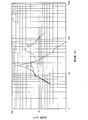
次に示す表1は、本実施の形態のHDDユニット100に用いるダンパ140をIIR10°のダンパと、IIR30°のダンパを用いた場合の実施の一例であり、図4は、当該実施の一例の結果を示すグラフである。また表1では、IIR10°のダンパに加えて、2mm角に切断した厚2mmの上記θ7の衝撃吸収材を図1(c)及び図3に示すように衝撃吸収部111としてシャーシ110に設けた場合についても記載している。このとき、衝撃吸収部111とハードディスク装置160とは、それぞれ2mmずつ間隔をあけて設けている。
Table 1 shown below is an example of the case where the
尚、表1では、衝撃吸収部111とハードディスク装置160との間隔を2mmに設定しているため、衝撃吸収部111を設けた場合には片振幅の値は計測していない。
In Table 1, since the distance between the

このように、弾性の小さいIIR10°のダンパを用いると大きな振幅で揺動し、振幅のエネルギーが大きくなるためハードディスク装置160に生じる最大加速度が大きくなる。また、弾性の大きいIIR30°のダンパを用いても、高周波数において、最大化速度が大きくなる。一方、IIR10°のダンパとθ7の衝撃吸収材とを用いると、振動周波数に関わらず最大加速度が小さくなることが示された。
As described above, when the
つまり、やわらかいダンパ140を用いて振動を和らげつつ振動周波数を下げて大きな振幅でハードディスク装置160を揺動させ、衝撃吸収部111に緩やかに接触させることによって揺動の振幅を小さくすると、振動を効果的に制振するすることができる。
That is, if the vibration amplitude is reduced by using the
なお本発明は、以上説示した各構成に限定されるものではなく、特許請求の範囲に示した範囲で種々の変更が可能である。また、上記の発明で説示された技術的手段を適宜組み合わせて得られる実施の形態についても本発明の技術的範囲に含まれる。 In addition, this invention is not limited to each structure demonstrated above, A various change is possible in the range shown to the claim. Embodiments obtained by appropriately combining the technical means explained in the above invention are also included in the technical scope of the present invention.
以上のように、本発明では、ハードディスク装置の側面に形成された弾性のやわらかいダンパによってハードディスク装置がHDDユニットのシャーシに固定され、大きな振幅でハードディスク装置を揺動させるとともに、ハードディスク装置の周囲に設けられた制振部材にハードディスク装置を緩やかに接触させ、ハードディスク装置の揺動を制振する構成である。そのためダンパと制振部材との相乗効果により、内蔵するハードディスク装置に生じた振動を効果的に制振することができる。そのため、本発明は、設置型、またはノートパソコンなどの持ち運び型のコンピュータの外部記録再生装置や、車載型道路ナビゲーションシステムの記録再生装置などの周知の大容量記録再生装置、またはその大容量記録再生装置を着脱可能に持ち運ぶ用途に利用することができるだけでなく、さらには、振動に弱い電子機器を着脱可能に持ち運ぶ用途に広く応用することが可能である。 As described above, in the present invention, the hard disk device is fixed to the HDD unit chassis by the elastic soft damper formed on the side surface of the hard disk device, and the hard disk device is swung with a large amplitude and provided around the hard disk device. In this configuration, the hard disk device is gently brought into contact with the vibration damping member so as to control the swing of the hard disk device. Therefore, the vibration generated in the built-in hard disk device can be effectively damped by the synergistic effect of the damper and the damping member. Therefore, the present invention provides a known large-capacity recording / reproducing apparatus such as an external recording / reproducing apparatus for a portable computer such as an installation type or a notebook personal computer, a recording / reproducing apparatus for an in-vehicle road navigation system, or a large-capacity recording / reproducing apparatus thereof. In addition to being able to be used for the purpose of detachably carrying the device, it can be widely applied to the purpose of detachably carrying an electronic device that is vulnerable to vibration.
100 HDDユニット(電子機器)
110 シャーシ(搭載筐体)
111 衝撃吸収部(制振手段)
112 衝撃吸収フレーム
120 FPCハーネス部
121 スリット
130 コネクタ接続部
131 コネクタ
140 ダンパ(振動減衰手段)
150 フロントグリル
151 換気スリット
160 ハードディスク装置
161 コネクタ
200 電子機器装着装置
230 コネクタ
100 HDD unit (electronic equipment)
110 Chassis (mounting chassis)
111 Shock absorber (vibration control means)
112
150
Claims (1)
上記電子機器は、対向する一対の側面に、弾性を有する複数個の振動減衰手段を備えており、
上記搭載筐体は、上記電子機器の上記振動減衰手段が設けられていない側面と対向する面に、制振手段を備えていることを特徴とする電子機器の搭載筐体。 An electronic device mounting enclosure,
The electronic device includes a plurality of vibration damping means having elasticity on a pair of opposing side surfaces,
The mounting case of electronic equipment, wherein the mounting case includes vibration damping means on a surface facing the side surface of the electronic device where the vibration damping means is not provided.
Priority Applications (1)
| Application Number | Priority Date | Filing Date | Title |
|---|---|---|---|
| JP2007241037A JP2009070530A (en) | 2007-09-18 | 2007-09-18 | Loading case for electronic equipment |
Applications Claiming Priority (1)
| Application Number | Priority Date | Filing Date | Title |
|---|---|---|---|
| JP2007241037A JP2009070530A (en) | 2007-09-18 | 2007-09-18 | Loading case for electronic equipment |
Publications (2)
| Publication Number | Publication Date |
|---|---|
| JP2009070530A true JP2009070530A (en) | 2009-04-02 |
| JP2009070530A5 JP2009070530A5 (en) | 2009-10-22 |
Family
ID=40606609
Family Applications (1)
| Application Number | Title | Priority Date | Filing Date |
|---|---|---|---|
| JP2007241037A Pending JP2009070530A (en) | 2007-09-18 | 2007-09-18 | Loading case for electronic equipment |
Country Status (1)
| Country | Link |
|---|---|
| JP (1) | JP2009070530A (en) |
Cited By (3)
| Publication number | Priority date | Publication date | Assignee | Title |
|---|---|---|---|---|
| WO2014111992A1 (en) * | 2013-01-18 | 2014-07-24 | 株式会社デンソー | Information server and on-vehicle device for transmitting and receiving data |
| CN104105368A (en) * | 2013-04-05 | 2014-10-15 | 日本电气株式会社 | Vibration suppression mechanism for an electronic device |
| US9846802B2 (en) | 2012-10-19 | 2017-12-19 | Nec Corporation | Passenger counting system, passenger counting method and passenger counting program |
Citations (3)
| Publication number | Priority date | Publication date | Assignee | Title |
|---|---|---|---|---|
| JPH0536695U (en) * | 1991-10-09 | 1993-05-18 | 京セラ株式会社 | Damper device for optical disk player |
| JP2002367361A (en) * | 2001-06-04 | 2002-12-20 | Matsushita Electric Ind Co Ltd | Impact resistance device for removable storage device |
| JP2004139670A (en) * | 2002-10-17 | 2004-05-13 | Sony Corp | Information storage device |
-
2007
- 2007-09-18 JP JP2007241037A patent/JP2009070530A/en active Pending
Patent Citations (3)
| Publication number | Priority date | Publication date | Assignee | Title |
|---|---|---|---|---|
| JPH0536695U (en) * | 1991-10-09 | 1993-05-18 | 京セラ株式会社 | Damper device for optical disk player |
| JP2002367361A (en) * | 2001-06-04 | 2002-12-20 | Matsushita Electric Ind Co Ltd | Impact resistance device for removable storage device |
| JP2004139670A (en) * | 2002-10-17 | 2004-05-13 | Sony Corp | Information storage device |
Cited By (6)
| Publication number | Priority date | Publication date | Assignee | Title |
|---|---|---|---|---|
| US9846802B2 (en) | 2012-10-19 | 2017-12-19 | Nec Corporation | Passenger counting system, passenger counting method and passenger counting program |
| WO2014111992A1 (en) * | 2013-01-18 | 2014-07-24 | 株式会社デンソー | Information server and on-vehicle device for transmitting and receiving data |
| CN104105368A (en) * | 2013-04-05 | 2014-10-15 | 日本电气株式会社 | Vibration suppression mechanism for an electronic device |
| US9901005B2 (en) | 2013-04-05 | 2018-02-20 | Nec Corporation | Vibration suppression mechanism for an electronic device |
| US9918398B2 (en) | 2013-04-05 | 2018-03-13 | Nec Corporation | Vibration suppression mechanism for an electronic device |
| CN104105368B (en) * | 2013-04-05 | 2019-03-15 | 日本电气株式会社 | The vibration suppressing mechanism of electronic equipment |
Similar Documents
| Publication | Publication Date | Title |
|---|---|---|
| JP4241910B2 (en) | Disk storage system and mounting system for head / disk assembly | |
| JP4915117B2 (en) | Vibration shock absorbing mechanism and content reproduction apparatus | |
| US20070014086A1 (en) | Bracket for disk drive | |
| US6633481B2 (en) | Media drive vibration attenuation system and method | |
| JP2003272371A (en) | Information storage device | |
| JPH10222972A (en) | Storage device and impact resistant accommodation container to be used therefor | |
| JP2007109379A (en) | Hard disk drive | |
| US6445587B1 (en) | Disk drive vibration/shock attenuation system and method | |
| US20100290154A1 (en) | Hard disk drive | |
| JP2009070530A (en) | Loading case for electronic equipment | |
| JP4193463B2 (en) | Information storage device | |
| JP2010061784A (en) | Flexure, head suspension assembly including the flexure, and hard disk drive including head suspension assembly | |
| JP2006079813A (en) | Hard disk drive assembly, mounting structure for hard disk drive, and mobile phone adopting the same | |
| JP3685469B2 (en) | Device having anti-vibration support mechanism | |
| JP4722184B2 (en) | Disk unit | |
| JP4093766B2 (en) | Stabilization mechanism for limiting rotational vibration in module housing | |
| JP2003314613A (en) | Vibration control structure of electronic apparatus | |
| JP2008210454A (en) | Mounting casing for electronic device having vibration-proof structure, and electronic device mounting device for detachably mounting same | |
| US7154757B1 (en) | Media drive vibration isolation and attenuation method and apparatus | |
| Mou et al. | Analysis of structurally transmitted vibration of HDD in notebook computer | |
| JPH05135560A (en) | Magnetic recording/reproducing device | |
| US20070050795A1 (en) | Disk drive unit | |
| JP3729837B2 (en) | Device having anti-vibration support mechanism | |
| KR100740802B1 (en) | Removable carrier for protecting a hard disk drive form shock | |
| JP4558760B2 (en) | Buffer member of magnetic disk device, shock buffering method, and electronic apparatus |
Legal Events
| Date | Code | Title | Description |
|---|---|---|---|
| A521 | Written amendment |
Free format text: JAPANESE INTERMEDIATE CODE: A523 Effective date: 20090903 |
|
| A621 | Written request for application examination |
Effective date: 20090903 Free format text: JAPANESE INTERMEDIATE CODE: A621 |
|
| A977 | Report on retrieval |
Free format text: JAPANESE INTERMEDIATE CODE: A971007 Effective date: 20100614 |
|
| A131 | Notification of reasons for refusal |
Free format text: JAPANESE INTERMEDIATE CODE: A131 Effective date: 20100622 |
|
| A02 | Decision of refusal |
Effective date: 20110111 Free format text: JAPANESE INTERMEDIATE CODE: A02 |