JP2009066420A - Gain optimization of volume images of medical diagnostic ultrasonic imaging - Google Patents
Gain optimization of volume images of medical diagnostic ultrasonic imaging Download PDFInfo
- Publication number
- JP2009066420A JP2009066420A JP2008238475A JP2008238475A JP2009066420A JP 2009066420 A JP2009066420 A JP 2009066420A JP 2008238475 A JP2008238475 A JP 2008238475A JP 2008238475 A JP2008238475 A JP 2008238475A JP 2009066420 A JP2009066420 A JP 2009066420A
- Authority
- JP
- Japan
- Prior art keywords
- hypersurface
- soft tissue
- data
- gain
- volume
- Prior art date
- Legal status (The legal status is an assumption and is not a legal conclusion. Google has not performed a legal analysis and makes no representation as to the accuracy of the status listed.)
- Pending
Links
Images


Classifications
-
- A—HUMAN NECESSITIES
- A61—MEDICAL OR VETERINARY SCIENCE; HYGIENE
- A61B—DIAGNOSIS; SURGERY; IDENTIFICATION
- A61B8/00—Diagnosis using ultrasonic, sonic or infrasonic waves
-
- A—HUMAN NECESSITIES
- A61—MEDICAL OR VETERINARY SCIENCE; HYGIENE
- A61B—DIAGNOSIS; SURGERY; IDENTIFICATION
- A61B8/00—Diagnosis using ultrasonic, sonic or infrasonic waves
- A61B8/48—Diagnostic techniques
- A61B8/483—Diagnostic techniques involving the acquisition of a 3D volume of data
-
- G—PHYSICS
- G01—MEASURING; TESTING
- G01S—RADIO DIRECTION-FINDING; RADIO NAVIGATION; DETERMINING DISTANCE OR VELOCITY BY USE OF RADIO WAVES; LOCATING OR PRESENCE-DETECTING BY USE OF THE REFLECTION OR RERADIATION OF RADIO WAVES; ANALOGOUS ARRANGEMENTS USING OTHER WAVES
- G01S7/00—Details of systems according to groups G01S13/00, G01S15/00, G01S17/00
- G01S7/52—Details of systems according to groups G01S13/00, G01S15/00, G01S17/00 of systems according to group G01S15/00
- G01S7/52017—Details of systems according to groups G01S13/00, G01S15/00, G01S17/00 of systems according to group G01S15/00 particularly adapted to short-range imaging
- G01S7/52023—Details of receivers
- G01S7/52033—Gain control of receivers
-
- G—PHYSICS
- G01—MEASURING; TESTING
- G01S—RADIO DIRECTION-FINDING; RADIO NAVIGATION; DETERMINING DISTANCE OR VELOCITY BY USE OF RADIO WAVES; LOCATING OR PRESENCE-DETECTING BY USE OF THE REFLECTION OR RERADIATION OF RADIO WAVES; ANALOGOUS ARRANGEMENTS USING OTHER WAVES
- G01S15/00—Systems using the reflection or reradiation of acoustic waves, e.g. sonar systems
- G01S15/88—Sonar systems specially adapted for specific applications
- G01S15/89—Sonar systems specially adapted for specific applications for mapping or imaging
- G01S15/8906—Short-range imaging systems; Acoustic microscope systems using pulse-echo techniques
- G01S15/8993—Three dimensional imaging systems
Abstract
Description
本発明は、医療診断超音波イメージングに関し、とりわけ、このようなイメージングを改善するためのゲインマップステージとダイナミックレンジマップステージと後処理マップステージとを含むバックエンドマッピングの1つまたは複数のステージを適応的に設定するシステムに関する。 The present invention relates to medical diagnostic ultrasound imaging, and in particular adapts one or more stages of backend mapping including a gain map stage, a dynamic range map stage, and a post-processing map stage to improve such imaging. Related to the system to set up automatically.
従来の超音波イメージングでは、Bモード信号が表示用のグレーレベルまたは色のレンジにマッピングされる前に、Bモード信号をゲインおよびダイナミックレンジのために調整する。表示される信号のダイナミックレンジは通常のように、ユーザによって、表示ダイナミックレンジ制御によって設定することができる。この制御は通常、画像のレンジおよびアジマス位置に依存しない。ゲインは通常、ユーザによって、マスタゲイン制御またはBゲイン制御と一緒にデプスゲイン補償(DGC)制御またはタイムゲイン補償(TGC)制御を使用して変化することができる。DGC制御およびTGC制御は通常、レンジ(軸次元)内でのみ可変であり、マスタゲインはレンジおよび横方向位置(アジマス位置)のどちらにも依存しない。また、デプスゲイン補償の他に付加的に横方向ゲインも提供するシステムも幾つか存在するが、これら2つの1次元ゲイン制御は、本当の2次元ゲイン制御の近似を含むだけである。 In conventional ultrasound imaging, the B-mode signal is adjusted for gain and dynamic range before the B-mode signal is mapped to a display gray level or color range. The dynamic range of the displayed signal can be set by the user by display dynamic range control as usual. This control is usually independent of image range and azimuth position. The gain can typically be changed by the user using depth gain compensation (DGC) control or time gain compensation (TGC) control along with master gain control or B gain control. DGC control and TGC control are usually variable only within the range (axis dimension), and the master gain does not depend on either the range or the lateral position (azimuth position). There are also some systems that provide lateral gain in addition to depth gain compensation, but these two one-dimensional gain controls only include an approximation of true two-dimensional gain control.
ゲインおよび表示ダイナミックレンジが適用されると、対数圧縮されたBモード信号が再量子化され、典型的には8ビットまたは256の量子化レベルに再量子化される。量子化幅(単位dB)は、ユーザによって選択されたダイナミックレンジと量子化レベルの数との比によって決定される。 When gain and display dynamic range are applied, the log-compressed B-mode signal is re-quantized and is typically re-quantized to an 8-bit or 256 quantization level. The quantization width (in dB) is determined by the ratio between the dynamic range selected by the user and the number of quantization levels.
量子化後、後処理マップを使用して、量子化レベルとグレーレベルまたは色のレンジとのマッピングを行う。このマップは、マップの事前設定されたセットから選択された1つとするか、または択一的に、ユーザ設定されたマップとすることができる。このようなマップは通常、レンジおよびアジマスに依存することもない。 After quantization, a post-processing map is used to map the quantization level to the gray level or color range. This map can be one selected from a preset set of maps, or alternatively, a user-configured map. Such maps are usually independent of range and azimuth.
市販の超音波イメージングシステム上では、ユーザが輝度レベルを調整するためにゲイン制御を使用することが多い。多くの場合、ユーザはたいてい、イメージ全体においてグレー値の狭いレンジ内に軟組織グレーレベルの局所平均を維持するように、ゲインを調整する。この有利なレンジはユーザによって一貫しており、多くの場合、ユーザは軟組織のグレーレベルを大まかに、0を黒にマッピングし255を白にマッピングする線形マップ上で第64グレーレベルに設定するようにゲインを調整する傾向にある。 On commercially available ultrasound imaging systems, users often use gain control to adjust the brightness level. In many cases, the user often adjusts the gain to maintain a local average of soft tissue gray levels within a narrow range of gray values throughout the image. This advantageous range is consistent from user to user, and in many cases the user will set the soft tissue gray level roughly to the 64th gray level on a linear map that maps 0 to black and 255 to white. There is a tendency to adjust the gain.
このようなゲイン調整は、ユーザインタフェースがある場合には2次元のイメージングで上手く機能する。全体のゲインは、取っ手によって制御されるか、またはすべてのデータに適用される1つの設定によって制御される。TGCまたはDGCは、異なる深度を表すスライダによって制御される。しかし、3次元での空間的変動をユーザインタフェースで具現化するのは困難である。 Such gain adjustment works well in two-dimensional imaging when there is a user interface. The overall gain is controlled by the handle or by one setting applied to all data. TGC or DGC is controlled by sliders representing different depths. However, it is difficult to realize spatial variation in three dimensions with a user interface.
米国特許第6579238号に、ゲインとダイナミックレンジとマッピングとを自動的に設定するための種々の実施形態が開示されている。これらのパラメータは、イメージング用の面を当てはめることによって最適化される。
本願発明の課題は、3次元での空間的変動をユーザインタフェースで具現化するためのゲイン最適化を提供することである。 An object of the present invention is to provide gain optimization for realizing a three-dimensional spatial variation with a user interface.
手始めに、以下に記載された有利な実施形態は以下のような方法とシステムと命令とコンピュータ読み出し可能な媒体とを含む。すなわち、3次元医療診断イメージングにおいて組織情報を等化し、ゲインを適応的に制御し、かつ/または、入力データを出力データにマッピングするための方法とシステムと命令とコンピュータ読み出し可能な媒体とを含む。超曲面が3つの空間的次元で入力データに当てはめられる。この超曲面は、より均一な軟組織レベルで入力値が出力値にマッピングされるようにゲインを調整するために使用される。 To begin with, the advantageous embodiments described below include the following methods, systems, instructions, and computer-readable media. That is, including methods, systems, instructions, and computer-readable media for equalizing tissue information, adaptively controlling gain, and / or mapping input data to output data in three-dimensional medical diagnostic imaging . A hypersurface is fitted to the input data in three spatial dimensions. This hypersurface is used to adjust the gain so that the input value is mapped to the output value with a more uniform soft tissue level.
第1の側面では、医療超音波イメージングシステムが、ゲインを適応的に制御するための方法を実施する。軟組織に相応する入力ボリュームデータのボクセルを識別する。この軟組織に相応するボクセルに3次元の超曲面を当てはめる。システムのゲインは、この当てはめられる超曲面に少なくとも部分的に依存して適応的に変化する。 In a first aspect, a medical ultrasound imaging system implements a method for adaptively controlling gain. Identify voxels of input volume data corresponding to soft tissue. A three-dimensional hypersurface is applied to the voxel corresponding to the soft tissue. The gain of the system adaptively changes depending at least in part on the hypersurface to be fitted.
第2の側面では、医療診断イメージングで組織情報を等化するためのシステムが提供される。ボリュームを表すデータに依存して超曲面を検出し、該超曲面に依存して該データを出力値にマッピングするように動作するように、プロセッサを構成する。出力値に応答して画像を表示するためにディスプレイが動作する。 In a second aspect, a system for equalizing tissue information in medical diagnostic imaging is provided. The processor is configured to operate to detect a hypersurface depending on the data representing the volume and to map the data to output values depending on the hypersurface. The display operates to display an image in response to the output value.
第3の態様においては、コンピュータ読み出し可能記憶媒体が、医療診断イメージングにおいて入力データを出力データにマッピングするためにプログラミングされたプロセッサによって実行可能な命令を表すデータを記憶している。この記憶媒体は、強度の空間的変動を、4次元空間に埋め込まれた3次元超曲面で抽出するための命令と、該超曲面に依存して入力データを出力データにマッピングするための命令と、該出力データに依存してイメージを表示するための命令とを含む。前記4次元空間は、3つの空間的次元と第4の強度次元とを含む。 In a third aspect, a computer readable storage medium stores data representing instructions executable by a processor programmed to map input data to output data in medical diagnostic imaging. The storage medium includes an instruction for extracting a spatial variation in intensity with a three-dimensional hypersurface embedded in a four-dimensional space, and an instruction for mapping input data to output data depending on the hypersurface. And an instruction for displaying an image depending on the output data. The four-dimensional space includes three spatial dimensions and a fourth intensity dimension.
本発明は特許請求の範囲によって規定され、以下の詳細な説明はこれらの請求項を限定するものとして解釈すべきではない。さらに本発明のさらなる有利な側面および利点は、以下の明細書で有利な実施例に基づいて説明され、請求の範囲において独立的または組み合わせで権利主張される。 The present invention is defined by the following claims, and the following detailed description should not be construed as limiting the claims. Further advantageous aspects and advantages of the invention will be set forth in the following specification based on advantageous examples, which are claimed independently or in combination in the claims.
ボリュームを表すボクセルに所属する強度は、同様のエコー発生性を有する組織が該ボリューム全体にわたってより均等な強度レベルを有するように、適応的に調整される。介在組織の吸収特性の差に起因する強度の変動が補償される。 The intensity belonging to the voxel representing the volume is adaptively adjusted so that tissue with similar echogenicity has a more even intensity level throughout the volume. Variations in strength due to differences in the absorption characteristics of the intervening tissue are compensated.
ボリュームを形成するデータの成分2次元フレームの手動調整を必要とするというよりもむしろ、この適応調整は自動である。この適応調整は、全体のボリュームに関係なく行われるデータの成分2次元フレームの自動調整を必要とするというよりむしろ、ボリュームデータに依存する。 Rather than requiring manual adjustment of the component 2D frames of the data forming the volume, this adaptive adjustment is automatic. This adaptive adjustment relies on volume data rather than requiring automatic adjustment of the component two-dimensional frame of the data, regardless of the overall volume.
軟組織に関連するボリュームのデータを識別する。たとえば、各ボクセルまたは各データの周辺のボリュームカーネル(たとえば3×3×3)を使用して、信号の確率分布の1次モーメント、2次モーメントまたはより高次のモーメントを評価する。軟組織の強度またはデータに超曲面を当てはめる。この超曲面は、3つの空間的次元と強度に対する第4の次元とを有する4次元空間に埋め込まれる。この超曲面は多項式によって記述されるか、または、ボリューム全体にわたって強度調整を緩慢に変化させる別の関数によって記述される。ボリューム内の各位置のターゲット強度と超曲面との差を、該ボリュームの各ボクセルに対するゲインとして計算する。このゲインを使用して、このボリュームまたは他のボリュームのデータを出力データにマッピングする。 Identify volume data associated with soft tissue. For example, each voxel or volume kernel around each data (eg, 3 × 3 × 3) is used to evaluate the first, second or higher moments of the signal probability distribution. Fit a hypersurface to soft tissue strength or data. This hypersurface is embedded in a four-dimensional space having three spatial dimensions and a fourth dimension for intensity. This hypersurface is described by a polynomial or by another function that slowly changes the intensity adjustment throughout the volume. The difference between the target intensity at each position in the volume and the hypersurface is calculated as the gain for each voxel in the volume. This gain is used to map this volume or other volume data to output data.
1つの実施形態では、米国特許第6579238号のシステムまたは方法が、超曲面ゲイン調整および/またはマッピングを実施する。この公報の開示内容は、引用によって本願発明に含まれるものとする。このシステムおよび方法の別の特徴、たとえばダイナミックレンジ調整および/またはノイズ補償は、使用してもしなくてもよい。別の実施形態では、超曲面ゲイン調整および/またはマッピングを、米国特許第6579238号に記載されたのと異なるシステムおよび方法で使用する。 In one embodiment, the system or method of US Pat. No. 6,579,238 performs hypersurface gain adjustment and / or mapping. The disclosure of this publication is included in the present invention by reference. Other features of the system and method, such as dynamic range adjustment and / or noise compensation, may or may not be used. In another embodiment, hypersurface gain adjustment and / or mapping is used in a different system and method than described in US Pat. No. 6,579,238.
「入力データ」または「ボリュームデータ」という用語は広義には、ビーム成形器出力(すなわちBモード信号)の振幅、強度または対数圧縮された振幅を指すのに使用され、また、ビーム成形器出力から導出または抽出された何らかの重要なパラメータを指すのにも使用される。このような重要なパラメータにはたとえば、ドップラー周波数シフトの平均速度および推定パワー(すなわちカラードップラーモード信号)と、ドップラー周波数シフトの推定パワースペクトル(すなわちスペクトルドップラーモード信号)とが含まれる。 The terms “input data” or “volume data” are used broadly to refer to the amplitude, intensity, or logarithmically compressed amplitude of the beamformer output (ie, B-mode signal), and from the beamformer output. It is also used to refer to some important parameter that has been derived or extracted. Such important parameters include, for example, the average speed and estimated power of the Doppler frequency shift (ie, color Doppler mode signal) and the estimated power spectrum of the Doppler frequency shift (ie, spectral Doppler mode signal).
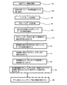
ここで図面を参照すると、図1は、組織情報を等化するための医療診断超音波イメージングシステム10のブロック図であある。図1に示されているように、送信ビーム成形器11が送受信スイッチ12を介して送信波形をトランスデューサアレイ13に印加する。このトランスデューサアレイ13は、この送信波形に応答して超音波パルスを生成し、該超音波パルスは、イメージングすべきボディBに方向づけされる。ボディBからの戻りエコーがトランスデューサアレイ13に当たり、該トランスデューサアレイ13はこの戻りエコーを受信信号に変換し、該受信信号は送受信スイッチ12を介して受信ビーム成形器14に伝送される。受信ビーム成形器14は、ボディB内の選択された位置からの受信信号が一貫して計算が合うように、適切な遅延および/または位相シフトを適用する。このビーム成形された信号は、レンダリングプロセッサ17に印加される前に、振幅検波器15とバックエンドプロセッサとに印加される。このバックエンドプロセッサは対数圧縮装置16を有する。
Referring now to the drawings, FIG. 1 is a block diagram of a medical diagnostic
レンダリングプロセッサ17は、グラフィック処理ユニット、グラフィックボード、グラフィックチップ、汎用プロセッサ、特定用途集積回路、デジタル信号プロセッサ、フィールドプログラマブルゲートアレイ、アナログ回路、デジタル回路、またはレンダリング用の別の現在公知のプロセッサまたは将来のプロセッサである。レンダリングプロセッサ17は、マッピング後にボリュームデータを受信する。受信されたデータは、完全なボリュームデータセットである。択一的にデータは、レンダリング中に必要とされるデータのマッピング等のマッピング中に受信される。レンダリングプロセッサ17は、ディスプレイ19に適した格子に基づいて表示値を生成する。この表示値は、バックエンドプロセッサからの出力値に応答する。レンダリングプロセッサ17は、レイキャスティング、表面レンダリング、または現在公知のボリュームレンダリングまたは今後開発されるボリュームレンダリングを実施する。
The rendering processor 17 may be a graphics processing unit, graphics board, graphics chip, general purpose processor, application specific integrated circuit, digital signal processor, field programmable gate array, analog circuit, digital circuit, or another currently known processor for rendering or the future. Processor. The rendering processor 17 receives the volume data after mapping. The received data is a complete volume data set. Alternatively, the data is received during mapping, such as data mapping required during rendering. The rendering processor 17 generates display values based on a grid suitable for the
メモリ20が検波器15からデータを受け取り、データをバックエンドプロセッサへ出力する。メモリ20は別の位置に配置することができ、たとえば対数圧縮ステージ16とマッピングステージ18との間に配置することができる。メモリ20は単独の装置であるが、それぞれ同一の目的に使用される2つ以上の装置の集合体とするか、または異なる目的に使用される2つ以上の装置の集合体とすることができる。
The
ボリュームを表すデータはメモリ20に記憶される。各入力データ(たとえば強度)はボクセルである。このデータは、等間隔の3次元格子上に補間または形成される。択一的に、ボリュームのデータは異方性であり、たとえば各ボクセルは、少なくとも1つの次元では比較的大きいサイズを有する。別の実施形態では、ボクセルは極座標格子に沿っており、たとえば、ボリューム内のデータの平行または非平行な受信2次元フレームに関連づけされている。
Data representing the volume is stored in the
メモリ20はまた、コンピュータ読み出し可能な記憶媒体とすることもでき、この記憶媒体には、プログラミングされたプロセッサによって実行可能な命令を表すデータが記憶されている。メモリ14および/または別のメモリが、バックエンドプロセッサを動作させるための命令、たとえばマッピングステージ18を動作させるための命令を記憶する。この命令は、医療診断イメージングにおいて入力データを出力データにマッピングするためのものである。本明細書において記載された処理、方法および/または技術を実施するための命令は、コンピュータ読み出し可能記憶媒体またはメモリ上に設けられ、この記憶媒体は例えば、キャッシュ、バッファ、RAM、リムーバブルメディア、ハードディスクドライブまたはそれ以外のコンピュータ読み出し可能記憶媒体である。コンピュータで読み出し可能な記憶媒体は、種々のタイプの揮発性記憶媒体および不揮発性記憶媒体を含む。図面または本明細書において説明した機能、動作またはタスクは、コンピュータ読み出し可能記憶媒体に記憶されている1つまたは複数の命令セットに応答して実行される。機能、動作またはタスクは、特定のタイプの命令セット、記憶媒体、プロセッサまたは処理ストラテジーに依存せず、またソフトウェア、ハードウェア、集積回路、ファームウェア、マイクロコードなどによって、単独でまたは組み合わせて実行されるようにしてもよい。同様に、処理ストラテジーは、マルチプロセシング、マルチタスク処理、並列処理などを含んでいてもよい。1つの実施形態において、命令はローカルシステムまたはリモートシステムによる読み出しのために、取り外し可能な媒体装置に記憶されている。別の実施形態において、命令はコンピュータネットワークまたは電話回線を介して転送するために、遠隔地に記憶されている。さらに別の実施形態において、命令は所与のコンピュータ、CPU、GPUまたはシステム内に記憶されている。
The
要素11〜17および19〜20はすべて、任意の適切な形態をとることができ、何らかの特定の構成に制限されない。たとえば、送受信ビーム成形器は、アナログ装置としてもデジタル装置としても構成することができ、シングルエレメント型のトランスデューサアレイや、種々の次元のフェーズドアレイも含めて、任意の適切なトランスデューサアレイを使用することができる。付加的に、システム10はトランスデューサアレイ13とディスプレイ19との間の信号経路に付加的なエレメントを有することができ、図中のエレメントのうち選択されたものを削除するか、または、図中のエレメントのうち幾つかの順序を交代することができる。たとえば、バックエンドプロセッサとレンダリングプロセッサ17との順序を変更し、たとえばメモリ20より前にスキャン変換部を設け、スキャン変換されたデータフレームがボリュームを表現するのに使用されるようにすることができる。別の例として、レンダリングプロセッサ17は別個のコンピュータ内にある。
Elements 11-17 and 19-20 can all take any suitable form and are not limited to any particular configuration. For example, the transmit / receive beamformer can be configured as either an analog or digital device, using any suitable transducer array, including single element transducer arrays and various dimensional phased arrays. Can do. Additionally, the
バックエンドプロセッサはまた、適応的な多次元バックエンドマッピングステージ18も有する。このマッピングステージ18は多くの形態をとることができ、たとえば、米国特許第6579238号に開示された実施形態のうちいずれかとすることができる。米国特許第6579238号の機能および相応の実施形態の任意の組み合わせを使用することもできる。米国特許第6579238号に開示されたように、ボリュームデータに基づいて、ノイズ、信号雑音比、ダイナミックレンジ処理、組織識別、ゲイン、マッピング、当てはめ、または別の側面を使用することができる。以下に別の実施形態が記載されている。
The backend processor also has an adaptive multidimensional
マッピングステージ18は、入力されたボリュームデータを出力ボリュームデータにマッピングするためのプロセッサを有する。プロセッサは、汎用プロセッサ、デジタル信号プロセッサ、特定用途集積回路、フィールドプログラマブルゲートアレイ、メモリ、デジタル回路、アナログ回路、それらの組み合わせ、または、入力データを出力データにマッピングするための他の現在公知のコンポーネントまたは将来開発されるコンポーネントである。
The
図2および3に、ボリューム全体で局所的ゲインを制御することにより、軟組織が実質的に一定の目標値で表示されるようにするための1つの実施形態が示されている。図2に、図1のマッピングステージ18′のこれらの実施形態のブロック図が示されている。図2に示されているようにマッピングステージ18′は、ノイズデータプロセッサ30と、軟組織プロセッサ32と、ゲインプロセッサ34とを有する。ノイズデータプロセッサ30は電子的ノイズの推定量を生成する。というのも、電子的ノイズはボリュームにわたって変化するからである。軟組織プロセッサ32は、ボリューム内の異なる位置における該ボリューム内の軟組織の強度を示す平滑化された超曲面を生成する。ゲインプロセッサ34はプロセッサ30および32からの出力を使用して、ボリュームに適用されるゲインを適応調整するか、またはゲインおよびダイナミックレンジの双方を適応調整する。択一的な実施形態では、ノイズデータプロセッサ30は設けられない。
FIGS. 2 and 3 illustrate one embodiment for allowing soft tissue to be displayed at a substantially constant target value by controlling local gain throughout the volume. FIG. 2 shows a block diagram of these embodiments of the
図3に、図2の要素の1つの実施形態の詳細なブロック図が示されている。図4に、図3の実施形態によって実施される方法のフローチャートが示されている。 FIG. 3 shows a detailed block diagram of one embodiment of the elements of FIG. FIG. 4 shows a flowchart of a method performed by the embodiment of FIG.
図3に示されたように、この実施形態におけるノイズデータプロセッサ30は、ローパスフィルタ40とデシメータ42とを有し、プロセッサ30は、ボリューム全体に分布された異なる位置の電子的ノイズの尺度を生成する。ノイズプロセッサ30は入力としてノイズボリュームを受け取る。すなわち、オフされた送信器によって取得されたボリュームを表すデータを受け取る。照射する圧力波が存在しない場合、得られる入力信号が、ボリューム内の位置に依存する現在主流のシステムノイズの尺度であるノイズデータ集合を形成する。ローパスフィルタ40がノイズボリュームを平滑化し、デシメータ42がこのフィルタリングされたノイズを比較的粗い格子にデシメートし、各次元でたとえば50ピクセルを測定する。別のデシメート係数を使用することができ、たとえば、音響的またはボリュームの格子で10×10×10ピクセルのデシメート係数を使用することができ、また、デシメートを使用しなくてもよい。このようなノイズボリュームによって、ボリューム内の位置に依存してシステムの局所的ノイズが供給される。
As shown in FIG. 3, the
軟組織プロセッサ32は、イメージングパラメータによって取得されたデータの画像ボリュームに応答する。この画像ボリュームは、画像中の軟組織に由来するデータを含む。軟組織プロセッサ32は、ボリュームデータセット中で軟組織に相応するデータを識別する。たとえば軟組織プロセッサ32は、ノイズプロセッサ30の相応の要素と同一または相違するローパスフィルタ44とデシメータ46とを含む。ノイズプロセッサ30からのフィルタリングおよびデシメートされたノイズボリュームは逆極性で、フィルタリングおよびデシメートされた画像ボリュームと加算器54で加算される。ノイズボリュームおよび画像ボリュームはこの実施例では、検波後、対数圧縮後の信号であるから、加算器54によって実施される加算は、2つのボリュームの関連する領域の信号雑音比(SNR)に等しい出力信号を生成する。SNRデータは比較器56に伝送され、該比較器56は出力としてSNRバイナリボリュームを生成する。このバイナリボリュームは、たとえば3dBまたは6dBである所定値を上回るSNRを特徴とするボリュームの領域では1に等しくセットされ、SNRが該所定値以下である領域では0にセットされる。このようにしてSNRバイナリボリュームは、軟組織画像データの候補となるのに十分に高い信号雑音比を有する画像ボリュームの領域を識別する。画像の高ノイズ低SNRの領域に相応する論理値0によって表されるSNRバイナリボリュームの部分であるこの領域は、軟組織の候補として見なされない。
The
軟組織プロセッサ32はまた、局所分散計算器48と、デシメータ50と、比較器52とによって、分散バイナリボリュームを生成する。これらのエレメントは、ボリュームデータセットの局所的な空間的分散を使用して、軟組織に特徴的な分散を有するボリュームデータセットの領域を識別する。
軟組織では、各分解能セルに存在する散乱体の数が多い。反射された信号間のランダムな干渉に起因して、完全に発達したスペックルが生じ、信号の振幅には、軟組織を表現するボリュームデータセットの領域にレイリー分布が生じる。この実施形態では、各ボクセル周辺の分解能セルの隣接関係で計算された局所的分散が、完全に発達したスペックルの局所的分散に類似する程度が、特定のボクセルが軟組織を表す尤度の尺度として使用される。この分散バイナリボリュームは、分散が軟組織イメージングに一致する領域では1に等しくセットされ、そうでない領域では0にセットされる。 In soft tissue, the number of scatterers present in each resolution cell is large. Due to random interference between the reflected signals, fully developed speckles occur, and the amplitude of the signal has a Rayleigh distribution in the region of the volume data set that represents soft tissue. In this embodiment, a measure of the likelihood that a particular voxel represents soft tissue to the extent that the local variance calculated on the adjacency relationship of the resolution cells around each voxel is similar to that of a fully developed speckle. Used as. This distributed binary volume is set equal to 1 in regions where the variance is consistent with soft tissue imaging, and is set to 0 in regions that are not.
局所的分散計算器48は、ボリュームデータセットをサブボリューム領域の格子に分割することによって動作する。このような領域のサイズは、各軸ごとにボリュームデータセットの分解能サイズより10倍大きいオーダとすることができる。より小さいサイズまたはより大きいサイズを使用することができる。
The
デシメータ50は、デシメータ42および46と同じスケールで動作するか、または異なるスケールで動作する。その後、デシメートされた分散ボリュームはボクセルごとに、比較器52において最小分散レベルおよび最大分散レベルと比較される。この比較はとりわけ、対数圧縮されたデータでは単純であり、ここでは、軟組織に特徴的な完全に発達したスペックル特性の分散が2×(5.57dB)となる。したがって、ボリューム内の軟組織の領域は、2×(5.57dB)に近い分散を有する完全に発達したスペックルによって表される。別の閾値を使用することも可能である。スペックルの実際の局所的分散は、超音波システムの信号処理経路に設けられたフィルタに起因して、理論値に等しくない場合がある。実際には、この分散は軟組織に似ているファントムに基づく測定によって検出される。
電子的ノイズの分散は軟組織の分散に近く、60で示されたAND演算がSNRバイナリボリュームと分散バイナリボリュームとを使用して、電子的ノイズを軟組織として誤分類するのを回避する。このAND演算は、デシメートされたSNRバイナリボリュームおよびデシメートされた分散バイナリボリュームのボクセルごとに行われる。このようにして得られた、デシメートされた組織バイナリボリュームの値は、SNRバイナリボリュームに関連する領域が低SNR比によって特徴づけられることを該SNRバイナリボリュームが示唆するか、または、分散バイナリボリュームに関連する領域が軟組織でないことを該分散バイナリボリュームが示唆する場合、0に等しい。SNRバイナリボリュームはすべての実施形態で必要であるわけではなく、ノイズが軟組織のように顕れる画像の領域が誤分類されるのを回避するために別の技術を使用することもできる。たとえば、ノイズ縮小技術を局所分散推定の前に適用することができる。 The variance of electronic noise is close to that of soft tissue, and the AND operation shown at 60 uses the SNR binary volume and the distributed binary volume to avoid misclassifying electronic noise as soft tissue. This AND operation is performed for each voxel of the decimated SNR binary volume and the decimated distributed binary volume. The value of the decimated tissue binary volume obtained in this way suggests that the region associated with the SNR binary volume is characterized by a low SNR ratio, or the distributed binary volume Equal to 0 if the distributed binary volume suggests that the relevant region is not soft tissue. SNR binary volumes are not required in all embodiments, and other techniques can be used to avoid misclassifying regions of the image where noise appears as soft tissue. For example, noise reduction techniques can be applied before local variance estimation.
デシメータ46からのフィルタリングおよびデシメートされた画像ボリュームデータセットと、AND素子60からのバイナリ組織ボリュームデータセットとは、プロセッサ62に入力として与えられ、軟組織強度を計算するのに使用される。とりわけプロセッサ62の出力は、同一の領域における組織バイナリボリュームの相応の値に依存する強度値を有するデシメートされたデータセットである。組織バイナリボリュームの相応の領域が、(該領域が軟組織に相応しないことを示唆する)論理値0に等しい場合、プロセッサ62の出力は、相応の領域の強度値を有さない。択一的に、組織バイナリボリュームが論理値1に等しい領域では、プロセッサ62の出力は、フィルタ44によってフィルタリングされデシメータ46によってデシメートされた相応の領域の強度値を含む。
The filtered and decimated image volume data set from decimator 46 and the binary tissue volume data set from AND
別の実施形態ではプロセッサ32は、ボリュームデータセットから計算されたモーメントに依存して、軟組織に相応するデータを識別する。たとえば、プロセッサ32はBモード強度のボクセルをフィルタリングする。任意のサイズのカーネルを使用することができ、たとえば3×3×3を使用することができる。対称的または非対称的なカーネルを使用することができる。デシメートされない各ボクセルごとに、またはデシメート後の他の各ボクセルごとに、ボリューム内のボクセルの周辺の隣接関係が、フィルタリングされた出力に寄与する。このフィルタリングは、1次モーメントを適用するか、または2次モーメントを適用するか、またはより高次のモーメントを適用する。1次モーメントの場合、カーネル内のボクセルは平均化される。2次モーメントの場合、カーネル内のボクセルはそれぞれ2乗され、加算された後、正規化される。1次モーメントおよび2次モーメントの双方を使用することができる。閾値は、得られたモーメントが軟組織を示唆するか否かを示し、たとえば2次モーメントが閾値を上回る場合、軟組織を示唆する。複数のモーメントまたは軟組織測定を使用する場合、閾値の組み合わせを使用するか、または1つの閾値のみによる測定結果の組み合わせを使用して、軟組織を識別することができる。たとえば、第1の閾値および第2の閾値をそれぞれ上回る1次モーメントおよび2次モーメントを有する領域は軟組織に相応し、他の領域は軟組織に相応しない。
In another embodiment,
1つの実施形態では、プロセッサ32は異なる種類の軟組織を識別する。異なる種類の軟組織は、異なる応答特性を有する。たとえば、1次モーメントのレンジおよび/または2次モーメントのレンジおよび/またはより高次のモーメントのレンジが、組織の種類を示唆する。適切な関数または閾値が、異なる種類の組織に関連する強度またはボクセルを識別する。軟組織の1つまたは複数の種類を識別するための別の実施形態を使用することができる。
In one embodiment, the
プロセッサ64において、該プロセッサ62によって供給されたボリュームデータセットに超曲面が当てはめられる。デシメートされたデータセットまたはデシメートされていないデータセットが、当てはめに使用される。当てはめのためのボリューム内のデータは、軟組織データである。軟組織データでないデータは使用されない。超曲面を定義する関数であればどのような関数も使用することができ、たとえば多項式関数を使用することができる。1つの実施形態では、線形関数または2次関数がこの超曲面を定義する。この超曲面は、軟組織を表す入力データである第4の次元を有する3つの空間的次元(すなわちボリューム)に当てはめられる。この入力データは、たとえば軟組織に関する強度である。
In the processor 64, a hypersurface is applied to the volume data set supplied by the
この超曲面は、局所的な軟組織平均強度の尺度を提供する。というのも、この超曲面はボリュームにわたって変動するからである。この平均は、局所的なデータに当てはめられる。この変動は、イメージング詳細を確保するために、たとえば超曲面を低次の関数または他の関数の多項式によって制限することにより、空間的に低くされる。1つの実施形態では、軟組織データはノイズを考慮せずに当てはめられる。別の実施形態では、SNRバイナリボリュームを使用して、ノイズによって与えられるボリュームの部分による超曲面の改悪を回避する。超曲面が軟組織データのデシメートされたボリュームに当てはめられる場合、プロセッサ64によって当てはめられる超曲面は急激に変動せず、異なるコントラストの軟組織間の移行部または接点の表示に干渉しない。1つの実施形態では、プロセッサ64はボリュームを6×6×6に分割するか、または他の格子に分割し、該格子の各領域ごとの軟組織平均強度値を計算した後に、超曲面をこの平均値に当てはめる。 This hypersurface provides a measure of local soft tissue average strength. This is because this hypersurface varies over volume. This average is fitted to local data. This variation is made spatially low, for example by constraining the hypersurface by a low order function or other function polynomials to ensure imaging details. In one embodiment, soft tissue data is fit without considering noise. In another embodiment, SNR binary volumes are used to avoid hypersurface degradation due to portions of the volume given by noise. If the hypersurface is applied to a decimated volume of soft tissue data, the hypersurface applied by the processor 64 does not vary abruptly and does not interfere with the display of transitions or contacts between soft tissues of different contrasts. In one embodiment, the processor 64 divides the volume into 6 × 6 × 6 or other grids, and after calculating the soft tissue average intensity value for each region of the grid, the hypersurface is averaged over this average. Apply to value.
プロセッサ64は、データの異なる種類ごとに別個の超曲面を決定することができる。たとえば、1つのデータセットは1つの種類の軟組織データであり、別のデータセットは別の種類の軟組織データである。これら2つのデータセットは、ボリュームを表現する入力データセットから識別されたデータを含む。異なる超曲面が当てはめられ、軟組織データの各種類ごとにそれぞれ1つの超曲面が当てはめられる。別の実施例として、ノイズに対して付加的な超曲面が決定される。この超曲面は、ノイズボリュームデータセットに当てはめられる。 The processor 64 can determine separate hypersurfaces for different types of data. For example, one data set is one type of soft tissue data, and another data set is another type of soft tissue data. These two data sets contain data identified from the input data set representing the volume. Different hypersurfaces are fitted and one hypersurface is fitted for each type of soft tissue data. As another example, an additional hypersurface for noise is determined. This hypersurface is applied to the noise volume data set.
このゲインプロセッサ34は、前記超曲面に依存して入力ボリュームのデータを出力値にマッピングするように動作する。マッピングされるこのデータは軟組織データを含み、別のデータを含むこともできる。たとえば入力ボリュームデータセットは、軟組織を示唆するために導出されたデータセットというより、マッピングされる。
The
この実施形態のゲインプロセッサ34は、プロセッサ64からの当てはめられる超曲面と、領域ごとまたはボクセルごとの軟組織目標強度レベルTTとの間の差を得るための加算器82を有する。加算器82の出力は軟組織ゲインGTであり、この軟組織ゲインGTは、レンジ、エレベーションおよびアジマスに応じて変動し、超曲面が組織局所平均に当てはめられて軟組織目標レベルTTで表示されるのに必要とされるゲインである。
The
1つの実施形態では、目標組織レベルにマッピングするためのゲインのみが加えられる。別の実施形態では、この組織ゲインGTは論理ブロック84に与えられ、この論理ブロック84は第2の入力GNも受け取る。信号GNは、ノイズ目標レベルTNとフィルタリングおよびデシメートされたノイズボリュームデータセットまたはノイズ超曲面の相応の値との間でボクセルごとまたは領域ごとに差をとる加算器80によって生成される。それゆえノイズゲインGNも、レンジ、エレベーションおよびアジマスに応じて変動し、局所平均ノイズレベルがノイズ目標レベルTNで表示されるのを保証するためのゲインを表す。論理ブロック84は、GFに等しい最終的な3次元ゲインを、GNおよびGTのうち低い方に設定する。この最終的な3次元ゲインGFは、ブロック86において画像ボリュームデータセットに加えられる。ゲインプロセッサ34は、ノイズ信号がノイズ目標レベルより低いボリュームのすべての部分で該ボリュームの軟組織領域がほぼ組織目標レベルTTで表示されるように、ゲインGFを設定する。ボリューム内においてノイズ強度INがノイズ目標レベルTNを上回る領域では、ノイズが不適切に増幅されないことを保証するために比較的低いゲインを使用する。
In one embodiment, only the gain for mapping to the target tissue level is added. In another embodiment, the tissue gain G T is provided to logic block 84, the logic block 84 also receives a second input G N. Signal G N is generated by the
幾つかの実施形態では、最終ゲインGFはたとえば最小2乗当てはめによって、デプスゲイン成分と、アジマスラテラルゲイン成分と、エレベーションラテラルゲイン成分と、アジマスラテラルゲイン傾斜成分と、エレベーションラテラルゲイン傾斜成分とに分解される。アジマスゲイン傾斜値および/またはエレベーションラテラルゲイン傾斜値が最小化するようにデプスゲイン成分を選択し、また、デプスゲインの変化とアジマスラテラルゲインの変化とエレベーションラテラルゲインの変化とが最小化されるようにマスタゲイン値を選択することが有利である。 In some embodiments, the final gain G F is least squares fit for example, a Depusugein component, and azimuth lateral gain component, and elevation lateral gain component, and azimuth lateral gain slope components, and elevation lateral gain slope component Is broken down into Select depth gain component to minimize azimuth gain slope value and / or elevation lateral gain slope value, and minimize changes in depth gain, azimuth lateral gain, and elevation lateral gain It is advantageous to select a master gain value.
1つの実施形態では、組織目標強度レベルがボリューム全体で一定であるが、別の実施形態では変動することもできる。超曲面は、軟組織に関連しない位置であっても、ボリューム全体にわたって目標レベルとの差を提供する。超曲面の当てはめと緩慢な変動に制限されることとに起因して、得られるゲインは、組織領域および非組織領域において大きく相違しない。非組織領域を表すデータがゲイン調整されると、強度レベルは軟組織領域と異なって維持される。 In one embodiment, the tissue target intensity level is constant throughout the volume, but may vary in other embodiments. The hypersurface provides a difference from the target level throughout the volume, even at locations that are not associated with soft tissue. Due to hypersurface fitting and being limited to slow fluctuations, the gain obtained is not significantly different in tissue and non-tissue regions. When the data representing the non-tissue region is gain adjusted, the intensity level is maintained differently from the soft tissue region.
別の実施形態では、複数の超曲面がマッピングに使用される。ゲインおよびダイナミックレンジの設定の組み合わせを使用することができる。たとえば、ゲインおよびダイナミックレンジの設定により、異なる種類の組織を異なる組織目標レベルにマッピングするか、または異なる組織目標レベルの近くにマッピングすることができる。択一的に、異なる超曲面がボリュームデータセットの異なるサブセットに適用され、組み合わされて、任意の優先度および関数を使用して1つの超曲面を成すか、または別個のレンダリングに使用される。たとえば、ノイズ超曲面が負のゲイン調整を行うのに使用される。組織目標値と軟組織超曲面との差は、ノイズの寄与を考慮するために増大される。 In another embodiment, multiple hypersurfaces are used for mapping. A combination of gain and dynamic range settings can be used. For example, different types of tissues can be mapped to different organizational target levels or close to different organizational target levels, depending on gain and dynamic range settings. Alternatively, different hypersurfaces are applied to different subsets of the volume data set and combined to form one hypersurface using arbitrary priorities and functions, or used for separate rendering. For example, a noise hypersurface is used to make negative gain adjustments. The difference between the tissue target value and the soft tissue hypersurface is increased to account for the noise contribution.
図4に、図3のシステムによって実施される方法のフローチャートが示されているが、異なるシステムを使用することもできる。医療用超音波イメージングシステムは、ゲインを適応制御するための方法を実施する。付加的なステップ、別のステップを設けるか、またはステップを少なくすることも可能である。たとえば、ノイズベースのステップ104,108および114が実施されない。別の例として、軟組織領域の識別において、ステップ110,112および114によって表されるのと異なる識別を使用することができる。各ステップは、図示の順序で実行してもよいし、または異なった順序で実行してもよい。
Although FIG. 4 shows a flowchart of a method performed by the system of FIG. 3, a different system can be used. A medical ultrasound imaging system implements a method for adaptively controlling gain. It is possible to provide additional steps, additional steps, or fewer steps. For example, noise based
ステップ100において、上記の適応ゲインの特徴が開始される。このことを行える手法は数多く存在する。たとえば、ユーザ要求に応答するかまたは時間間隔で自動的に、適応ゲインを開始する。たとえば、設定された数のボリュームスキャンごとに、または設定された秒数ごとに、適応ゲインを自動的に開始することができる。別の例として、変化が検出されることによってゲインの計算がトリガされる。
In
適応ゲインがブロック100において開始されると、ステップ102においてシステムの3次元のイメージング取得パラメータが、事前選択された値に設定される。この事前選択された値は、適応ゲインプロセッサの動作を最適化する。一例として、以下の一般的なガイドラインが1つの実施形態において適していることが判明した:
可能性のある非常に幅広く異なるイメージング状況において、ボリュームのすべての位置で飽和を引き起こすことなくボリューム全体にわたって可能な限り最高の信号雑音比が維持されるように、ゲインおよびダイナミックレンジを決定する。このことにより、信号が弱い領域が適応ゲインプロセッサによって考慮されることが保証される。別のパラメータおよび/または目的を使用することもできる。事前選択された値は、ユーザによって変化または変更することができる。この事前選択された値は、受信データに適応することができる。事前選択された値は、異なるイメージングアプリケーションごとに異なることができる。
When adaptive gain is started at
Gain and dynamic range are determined so that the highest possible signal-to-noise ratio is maintained throughout the volume without causing saturation at all positions of the volume in a very wide variety of possible imaging situations. This ensures that areas with weak signals are taken into account by the adaptive gain processor. Other parameters and / or purposes can also be used. The preselected value can be changed or changed by the user. This preselected value can be adapted to the received data. The preselected value can be different for different imaging applications.
画像取得パラメータが選択されると、ステップ104においてこの画像取得パラメータを使用して1つまたは複数のノイズデータ集合を取得し、ステップ106において画像ボリュームデータ集合を取得する。たとえば、ノイズボリュームデータ集合は通常の画像データ集合であるが、送信器がオフされているという点で異なる。受信器およびプロセッサは、ボリュームにわたってスキャンすることにより、信号を受け取る。送信器がオフされているので、本当のエコー信号は存在せず、このデータ集合に顕れる信号はすべて、システムノイズを表すかまたは電子的ノイズを表す。このノイズボリュームデータ集合はブロック108において、低SNRを特徴とする領域を識別するのに使用される。画像ボリュームデータセットはどのような様式でもよく、たとえば、造影剤が添加された組織または造影剤が未添加である組織の基本波イメージングまたは高調波イメージングを含んでもよい。
Once the image acquisition parameters are selected, one or more noise data sets are acquired using the image acquisition parameters in
ステップ110,112および114は、軟組織に相応する入力ボリュームデータのボクセルを識別するために機能する。たとえば、ステップ106においてボリュームを表すBモード強度のデータ集合が取得されて処理されることにより、軟組織に関連するボクセルまたは領域が検出される。
ステップ110において、入力ボリュームデータの変動性の統計的尺度が検出され、たとえば各ボクセルまたは選択された領域の変動性の統計的尺度が検出される。ステップ110において、振幅検波され対数圧縮された信号の空間的または時間的な平均が1次モーメントとして使用される。択一的に、ノイズ出力の局所平均によって正規化されたノイズ出力の空間的分散を2次モーメントとして使用することができる。たとえば、圧縮前の信号に関して、正規化された空間的分散を検出し、この正規化された空間的分散を、この圧縮前の信号の局所平均によって正規化することができる。3次元カーネルを有する確率分布の1次モーメント、2次モーメントまたはより高次のモーメント。4次元空間は、3つの空間的次元とデータ(たとえば強度)次元とに相応する。
In
各統計的尺度は、入力ボリュームデータの各ボクセルまたは各領域の周囲の3次元領域の関数である。この領域は、それぞれ2を上回るN×M×P領域等である任意のサイズとすることができる。より大きな領域を使用することもできる。この領域は、対称的であるかまたは非対称的である。この領域は、デシメートなしのボクセル間隔であるか、またはデシメート後のボクセル間隔に相応する。 Each statistical measure is a function of each voxel or three-dimensional region around each region of the input volume data. This region can be of any size, such as an N × M × P region greater than 2 each. Larger areas can also be used. This region is symmetric or asymmetric. This region corresponds to the voxel spacing without decimating or after decimating.
この変動性の統計的尺度は、横方向および軸方向の軸とエレベーション軸のうちいずれか1つの軸上で計算するか、またはこれらの軸のうちいずれか2つの軸上で計算するか、または3つすべての軸上で計算することができる。上記の例は、3つの空間的次元における分散を計算し、たとえばエレベーション軸、アジマス軸および軸方向の軸における分散を計算する。これら3つの空間的次元は、ボリュームドメイン(たとえばx,y,z)に存在するか、またはスキャンドメイン(レンジ、エレベーション、アジマス)に存在することができる。 This statistic measure of variability is calculated on any one of the transverse and axial axes and the elevation axis, or on any two of these axes, Or it can be calculated on all three axes. The above example calculates the variance in three spatial dimensions, for example, the variance in the elevation axis, the azimuth axis, and the axial axis. These three spatial dimensions can exist in the volume domain (eg, x, y, z) or in the scan domain (range, elevation, azimuth).
ステップ112および114において、軟組織に相応する画像ボリュームデータ集合の領域が検出される。軟組織に相応する入力ボリュームデータのボクセルは、前記統計的尺度のうち1つまたは複数の統計的尺度の少なくとも一部に基づいて検出される。別の情報からの軟組織情報を示すために、閾値または別の関数を使用することができる。米国特許第6579238号に開示された軟組織検出または軟組織検出を支援する技術等の、別の技術を使用することもできる。1つの実施形態では、1次モーメントおよび2次モーメントの双方が使用される。たとえば異なる閾値を適用して、1つより多くの種類の軟組織を識別することができる。
In
ステップ114において、ブロック108において検出された低SNRを特徴とするボリュームの領域を使用することにより、軟組織として識別された領域が、画像のノイズ含有領域の外側にあることを保証する。局所コヒーレンス係数を使用して、高い音響的ノイズまたはクラッタの領域がマッピング判定から排除されることを保証することができる。局所コヒーレンス係数は、遅延およびアポディゼーションされた信号の受信チャネルにわたるコヒーレント(位相敏感)/インコヒーレント(位相敏感でない)の和の比として定義される。Rigby による米国特許第5910115号の記載を参照されたい。低いコヒーレンス係数は強い位相収差を示唆する。すなわち、音響ノイズまたはクラッタのレベルが高いことを示唆する。コヒーレンス係数を使用して、クラッタによって得られたボリュームの領域を無視することができる。
In
上記のように、軟組織識別を変動性の統計的尺度に基づいて行うことができる。択一的に、軟組織を識別するために別の手法を使用することができ、たとえば画像信号の振幅に基づく手法を使用することができる。Klesenski による米国特許第5579768号の記載を参照されたい。 As described above, soft tissue identification can be performed based on a statistical measure of variability. Alternatively, another approach can be used to identify soft tissue, for example, an approach based on the amplitude of the image signal. See U.S. Pat. No. 5,579,768 to Klesenski.
ボリューム内の軟組織情報を使用して、強度または別のデータの空間的変動が抽出される。この抽出は、4次元空間に埋め込まれた3次元の超曲面によって実現される。この空間の4つの次元は、3つの空間的次元と、強度またはデータの第4の次元とである。 The soft tissue information in the volume is used to extract intensity or another data spatial variation. This extraction is realized by a three-dimensional hypersurface embedded in a four-dimensional space. The four dimensions of this space are the three spatial dimensions and the fourth dimension of intensity or data.
ステップ116において3次元の超曲面を、デシメートされたかデシメートされていないボリューム全体にわたる軟組織ボクセルに当てはめる(たとえばBモード強度値)。この超曲面は3つの空間的次元に沿って当てはめられる。超曲面を当てはめるための現在公知のアルゴリズムまたは処理、または、将来開発されるアルゴリズムまたは処理のうち任意のアルゴリズムまたは処理を使用することができる。1つの実施形態では、超曲面は多項式関数に基づく。軟組織データに対して、多項式の制限を満たす3次元面の最良の当てはめが求められる。線形関数、2次関数または別の多項式関数を使用することができる。超曲面は一般的に、F(x,y,z,w・・・)=0の形態の数式によって記述される。変数x,y,z,w・・・がn次元の空間の次元に相応する場合、超曲面は埋め込まれている。Fが2次の多項式である特別なケースでは、超曲面は2次超曲面と称される。アプリケーションが異なるごとに異なる超曲面を使用することができ、たとえば、より均質に応答する器官をイメージングするために、より緩慢に変動する超曲面を提供することができる。任意の技術を使用することができ、たとえば米国特許第6579238号に開示された当てはめ技術を使用することができる。
In
1つより多くの超曲面を当てはめることができる。たとえば、超曲面を異なるデータ集合に当てはめることができる。データ集合は、異なる組織からの応答または組織およびノイズからの応答を表す。同種類の超曲面が異なるデータ集合に独立して当てはめられる。択一的に、データ集合が異なるごとに異なる超曲面が当てはめられ、たとえば、異なるコントラストを提供するか、または、異なる超曲面に当てはめるための異なる多項式を提供する。 More than one hypersurface can be fitted. For example, hypersurfaces can be applied to different data sets. The data set represents responses from different tissues or responses from tissues and noise. The same kind of hypersurface can be applied independently to different data sets. Alternatively, different hypersurfaces are fitted for different data sets, for example providing different contrasts or different polynomials for fitting to different hypersurfaces.
ステップ118において、各位置において超曲面の振幅を有する信号が、画像の一部分または全体にわたる軟組織目標値で表示されるかまたは該軟組織目標値の近くで表示されるように、局所ゲインを適応的に変化する。このゲインは、入力ボリュームデータ集合および/または異なるボリュームデータ集合(たとえば連続的に取得されボリュームを表すデータ集合)をマッピングするために使用される。この超曲面は、データのゲインの適応変化をボリューム内の位置に依存して提供する。このボクセルは出力値の軟組織レンジにマッピングされる。レンダリングすべき画像内の軟組織の領域の平均振幅は実質的に目標表示値にある。これは実質的に、値のレンジとのマッピングを考慮し、たとえば10個の強度レベル内のマッピングを考慮する。
In
この軟組織目標値または目標表示値を設定する手法は数多く存在する。目標表示値は、単に記憶された値とするか、またはユーザ選択された値とするか、または周辺光に応答して適応的に検出される値とすることができる。択一的に軟組織目標レベルは、現在呼び出された処理後の曲線に依存する。とりわけ、ユーザ制御可能な値またはユーザ事前定義可能な値を軟組織目標グレイレベルTGとして使用することができる。TGの表示グレイレベルにマッピングされる信号強度レベルに処理後曲線が選択されると必ず、TTは定義される。ゲインの設定に別のファクタも考慮することができ、たとえばノイズ、SNRまたはダイナミックレンジを考慮することができる。 There are many methods for setting the soft tissue target value or target display value. The target display value can be simply a stored value, a user-selected value, or a value that is adaptively detected in response to ambient light. Alternatively, the soft tissue target level depends on the currently called post processing curve. In particular, a user controllable value or a user predefinable value can be used as the soft tissue target gray level TG . T T is defined whenever a post-processing curve is selected for a signal strength level that maps to a display gray level of TG . Other factors can be taken into account in the gain setting, for example noise, SNR or dynamic range.
1つより多くの超曲面に対してマッピングするためには、ゲイン設定および別の設定の双方を使用することができる。たとえば、ダイナミックレンジは2つ以上の3次元超曲面に依存して変化する。ゲインも、2つ以上の超曲面に依存することができる。択一的に、ゲインは1つの超曲面に依存し、別の設定は別の超曲面に依存する。 To map to more than one hypersurface, both the gain setting and another setting can be used. For example, the dynamic range varies depending on two or more three-dimensional hypersurfaces. Gain can also depend on more than one hypersurface. Alternatively, the gain depends on one hypersurface and another setting depends on another hypersurface.
たとえば、2つ以上の異なる種類の組織に対して、または組織とノイズとに対して、複数の超曲面を使用することができる。たとえば、ノイズ信号は3次元で供給され、現在存在するノイズを示し、たとえばクラッタ、電子回路ノイズ、収差または別のノイズを示す。ノイズ超曲面はノイズ信号に当てはめられる。ゲイン設定または別の設定は、ノイズ超曲面に依存して適応的に変化する。ゲインも、組織に対応する超曲面に依存することができる。たとえば、特定のボクセル位置の最小ゲインを選択するか、またはこれを平均化することにより、超曲面または得られるゲイン値が組み合わせられる。 For example, multiple hypersurfaces can be used for two or more different types of tissue, or for tissue and noise. For example, the noise signal is supplied in three dimensions and indicates noise that is currently present, such as clutter, electronic circuit noise, aberrations or other noise. The noise hypersurface is applied to the noise signal. The gain setting or another setting changes adaptively depending on the noise hypersurface. The gain can also depend on the hypersurface corresponding to the tissue. For example, by selecting or averaging the minimum gain for a particular voxel location, the hypersurface or resulting gain value is combined.
ステップ120において、マッピングから出力されたデータに依存して画像を表示する。データをフィルタリングするか、または3次元格子に補間するか、または別の手法でレンダリング前に処理することができる。出力されるデータは、ボリュームを表すボクセルを含むか、または、各次元に沿った複数のボクセルにわたって分布されたボクセルを含む。この出力データを使用して、レイキャスティング、強度投影(最大、最小、平均)、表面レンダリング、または別のボリュームレンダリングを行うことができる。アルファブレンディング、オパシティ処理、シェーディング処理または別のレンダリング処理を使用することができる。変換関数を適用することができる。レンダリングによって、2次元スクリーン上に観察方向からの3次元表現が作成される。 In step 120, an image is displayed depending on the data output from the mapping. Data can be filtered, interpolated into a three-dimensional grid, or otherwise processed before rendering. The output data includes voxels representing the volume, or includes voxels distributed over a plurality of voxels along each dimension. This output data can be used for ray casting, intensity projection (maximum, minimum, average), surface rendering, or another volume rendering. Alpha blending, opacity processing, shading processing or another rendering process can be used. A conversion function can be applied. Rendering creates a three-dimensional representation from the viewing direction on a two-dimensional screen.
多くの択一的手段が可能である。実際には、アナログ信号処理技術およびデジタル信号処理技術の最も広いレンジを使用して、上記の基本的機能を実施することができる。上記の適応ゲインプロセッサの1つの実施形態に、プログラミングされたコンピュータがある。たとえば、適応ゲインと、オプションとして適応的に検出されるダイナミックレンジとを、トランスデューサアレイ13およびディスプレイ19との間の信号経路上の所望の位置における画像信号に適用することができる。双方とも、スキャン変換と対数圧縮と検波とを行う前または行った後とすることができる。適応ゲインプロセッサは、検波と対数圧縮とスキャン変換とが行われる前または行われた後に、RF信号、IF信号またはベースバンド信号で動作することができる。
Many alternative means are possible. In practice, the basic functions described above can be implemented using the widest range of analog and digital signal processing techniques. One embodiment of the adaptive gain processor described above is a programmed computer. For example, adaptive gain and optionally adaptively detected dynamic range can be applied to the image signal at a desired location on the signal path between the
上記の例では入力信号は、異なるバックエンドゲインステージを適切に制御することにより、出力信号値の軟組織レンジまたはノイズレンジに適応的にマッピングされる。しかし、所望の出力信号値が得られるように、単独で、または1つまたは複数のバックエンドゲインステージのゲイン変化と組み合わせて、フロントエンドゲインステージのゲインを変化することもできる。 In the above example, the input signal is adaptively mapped to the soft tissue range or noise range of the output signal value by appropriately controlling different backend gain stages. However, the gain of the front end gain stage can be changed alone or in combination with the gain change of one or more back end gain stages so as to obtain the desired output signal value.
上記の詳細な説明は図解のためのものであり、本発明を限定しない。本発明の範囲を定義するのは、等価的なすべてのものも含めた特許請求の範囲のみである。 The above detailed description is for purposes of illustration and not limitation. It is only the claims, including all equivalents, that define the scope of the invention.
Claims (20)
軟組織に相応する入力ボリュームデータのボクセルを識別し(112)、
3次元の超曲面を、該軟組織に相応するボクセルに当てはめ(116)、
該医療用超音波イメージングシステム(10)のゲインを、少なくとも部分的に、当てはめられた該超曲面に基づいて適応的に変化する(118)
ことを特徴とする方法。 In a method for adaptively controlling gain in a medical ultrasound imaging system (10),
Identify voxels of input volume data corresponding to soft tissue (112);
Fitting a three-dimensional hypersurface to a voxel corresponding to the soft tissue (116);
The gain of the medical ultrasound imaging system (10) is adaptively changed (118) based at least in part on the applied hypersurface.
A method characterized by that.
該入力ボリュームデータの変動性の次のような統計的尺度、すなわち、各統計的尺度は該入力ボリュームデータの各ボクセルの周辺の3次元の領域に依存する統計的尺度を決定するステップ(110)と、
少なくとも部分的に該統計的尺度に基づいて、該軟組織に相応する入力ボリュームデータのボクセルを識別するステップ(112)
とを有する、請求項1記載の方法。 Identifying (112) voxels of input volume data corresponding to the soft tissue,
The following statistical measures of the variability of the input volume data, i.e., each statistical measure determines a statistical measure that depends on a three-dimensional region around each voxel of the input volume data (110). When,
Identifying voxels of input volume data corresponding to the soft tissue based at least in part on the statistical measure (112)
The method of claim 1, comprising:
ノイズ超曲面を該ノイズ信号に当てはめるステップ(116)
とを有し、
前記ゲインを適応的に変化するステップ(118)において、該ゲインを前記超曲面と該ノイズ超曲面とに依存して適応的に変化する(118)、請求項1記載の方法。 Supplying a three-dimensional noise signal indicative of currently existing noise (104);
Applying a noise hypersurface to the noise signal (116)
And
The method of claim 1, wherein in the step of adaptively changing the gain (118), the gain is adaptively changed (118) depending on the hypersurface and the noise hypersurface.
前記3次元の超曲面は、該Bモード強度に当てはめられる3つの空間的次元を含む、請求項1記載の方法。 The input volume data is B-mode intensity,
The method of claim 1, wherein the three-dimensional hypersurface includes three spatial dimensions that are fitted to the B-mode intensity.
前記3次元の超曲面を当てはめるステップ(116)において、該3次元の超曲面を該第1の集合のボクセルに当てはめ(116)、付加的な3次元の超曲面を該第2の集合のボクセルに当てはめ(116)、
前記ゲインを適応的に変化するステップ(118)において、ダイナミックゲインを該3次元の超曲面と該付加的な3次元の超曲面とに依存して変化する(118)、請求項1記載の方法。 In the step of identifying voxels (112), a first set of voxels corresponding to the first type of soft tissue and a second set of voxels corresponding to the second type of soft tissue are identified (112);
In the step (116) of applying the three-dimensional hypersurface, the three-dimensional hypersurface is applied to the first set of voxels (116), and an additional three-dimensional hypersurface is applied to the second set of voxels. Fit to (116),
The method of claim 1, wherein in the step of adaptively changing the gain (118), the dynamic gain is changed (118) depending on the three-dimensional hypersurface and the additional three-dimensional hypersurface. .
ボリュームを表すデータに依存して超曲面を決定し、該超曲面に依存して該データを出力値にマッピングするように動作するプロセッサ(18)と、
該出力値に応答して画像を表示するように構成されたディスプレイ(19)
とを有することを特徴とするシステム。 In a system (10) for equalizing tissue information in medical ultrasound imaging,
A processor (18) operable to determine a hypersurface depending on data representing the volume and to map the data to an output value depending on the hypersurface;
A display (19) configured to display an image in response to the output value
The system characterized by having.
該データは超音波強度を有し、
該超曲面の当てはめ(116)は多項式の関数である、請求項11記載のシステム。 The processor (18) is configured to determine the hypersurface by fitting the hypersurface to the data in three spatial dimensions;
The data has ultrasonic intensity,
The system of claim 11, wherein the hypersurface fit (116) is a polynomial function.
該プロセッサ(18)は前記超曲面を、軟組織に相応するデータに依存して、該ボリュームの別のデータには依存せずに決定する、請求項11記載のシステム。 The processor (18) is configured to identify data corresponding to soft tissue depending on the moments calculated for different adjacencies of the data in the volume;
12. The system according to claim 11, wherein the processor (18) determines the hypersurface depending on data corresponding to soft tissue and not on other data of the volume.
該異なる種類のうち1つの種類の軟組織に対して前記超曲面を決定し、該異なる種類のうち別の種類の軟組織に対して付加的な超曲面を決定し、
該超曲面および付加的な超曲面の双方に依存してマッピングするように構成されている、請求項11記載のシステム。 The processor (18) identifies different types of soft tissue;
Determining the hypersurface for one type of soft tissue of the different types, determining additional hypersurfaces for another type of soft tissue of the different types,
The system of claim 11, wherein the system is configured to map depending on both the hypersurface and the additional hypersurface.
前記超曲面と該付加的な超曲面とに依存してマッピングするように構成されている、請求項11記載のシステム。 Said processor (18) determines an additional hypersurface for noise;
The system of claim 11, configured to map depending on the hypersurface and the additional hypersurface.
該命令は、プログラミングされたプロセッサ(18)によって実行可能であり、
該命令は、
強度の空間的変動を、3つの空間的次元と第4の強度次元とを含む4次元空間に埋め込まれた3次元の超曲面で抽出するための命令(116)と、
該超曲面に依存して該入力データを該出力データにマッピングするための命令(118)と、
該出力データに依存して画像を表示するための命令(120)
とを含むことを特徴とする、コンピュータ読み出し可能な記憶媒体。 In a computer readable storage medium (20) storing data representing instructions for mapping input data to output data in medical diagnostic imaging,
The instructions are executable by a programmed processor (18);
The instruction is
An instruction (116) for extracting a spatial variation in intensity with a three-dimensional hypersurface embedded in a four-dimensional space including three spatial dimensions and a fourth intensity dimension;
An instruction (118) for mapping the input data to the output data depending on the hypersurface;
Instruction for displaying an image depending on the output data (120)
And a computer-readable storage medium.
前記強度の空間的変動を抽出するステップ(116)において、該モーメントによって区別された軟組織に依存して抽出する、請求項16記載の命令。 A first-order moment, a second-order moment, or a higher-order moment of a probability distribution is estimated by a three-dimensional kernel around each voxel in the four-dimensional space (110), and each voxel includes input data;
17. Instruction according to claim 16, wherein in the step of extracting (116) the spatial variation in intensity, the extraction is dependent on the soft tissue distinguished by the moment.
Applications Claiming Priority (1)
| Application Number | Priority Date | Filing Date | Title |
|---|---|---|---|
| US11/901,675 US8435180B2 (en) | 2007-09-17 | 2007-09-17 | Gain optimization of volume images for medical diagnostic ultrasonic imaging |
Publications (2)
| Publication Number | Publication Date |
|---|---|
| JP2009066420A true JP2009066420A (en) | 2009-04-02 |
| JP2009066420A5 JP2009066420A5 (en) | 2011-11-04 |
Family
ID=40418344
Family Applications (1)
| Application Number | Title | Priority Date | Filing Date |
|---|---|---|---|
| JP2008238475A Pending JP2009066420A (en) | 2007-09-17 | 2008-09-17 | Gain optimization of volume images of medical diagnostic ultrasonic imaging |
Country Status (3)
| Country | Link |
|---|---|
| US (1) | US8435180B2 (en) |
| JP (1) | JP2009066420A (en) |
| DE (1) | DE102008046019B4 (en) |
Cited By (4)
| Publication number | Priority date | Publication date | Assignee | Title |
|---|---|---|---|---|
| KR101097642B1 (en) * | 2010-10-29 | 2011-12-22 | 삼성메디슨 주식회사 | Data processing system for performing compression and decompression upon ultrasound data |
| WO2012176837A1 (en) * | 2011-06-23 | 2012-12-27 | 株式会社東芝 | Ultrasonic diagnostic device and method |
| WO2013002351A1 (en) * | 2011-06-29 | 2013-01-03 | 株式会社 東芝 | Ultrasound diagnostic device and medical image processing device |
| US8724880B2 (en) | 2011-06-29 | 2014-05-13 | Kabushiki Kaisha Toshiba | Ultrasonic diagnostic apparatus and medical image processing apparatus |
Families Citing this family (12)
| Publication number | Priority date | Publication date | Assignee | Title |
|---|---|---|---|---|
| US20090112096A1 (en) * | 2007-10-29 | 2009-04-30 | Aloka Co., Ltd. | Methods and apparatus for ultrasound imaging |
| US20100130860A1 (en) * | 2008-11-21 | 2010-05-27 | Kabushiki Kaisha Toshiba | Medical image-processing device, medical image-processing method, medical image-processing system, and medical image-acquiring device |
| JP2011019202A (en) * | 2009-07-10 | 2011-01-27 | Sony Corp | Image signal processing apparatus and image display |
| CN103845077B (en) * | 2012-12-05 | 2016-01-20 | 深圳迈瑞生物医疗电子股份有限公司 | Ultrasonoscopy gain optimization method and the Gain Automatic optimization device of ultra sonic imaging |
| CN104306023B (en) * | 2014-10-24 | 2016-05-25 | 西安电子科技大学 | Ultrasonic imaging Fast implementation based on compressed sensing |
| CN104306022B (en) * | 2014-10-24 | 2016-05-25 | 西安电子科技大学 | Realize the method for compressed sensing ultrasonic imaging with GPU |
| KR102270712B1 (en) | 2014-11-28 | 2021-06-30 | 삼성메디슨 주식회사 | Apparatus and method for volume rendering |
| KR101652728B1 (en) * | 2015-02-13 | 2016-08-31 | 서강대학교산학협력단 | Ultrasonic image quality improving method and ultrasonic imaging apparatus using the same |
| US20170109922A1 (en) * | 2015-10-15 | 2017-04-20 | Michal Kulon | System and method for facilitating assessment of the bowel course and facilitation of transition point detection on cross-sectional radiologic digital images by elimination of air-fluid levels during image post-processing. |
| US20180042577A1 (en) * | 2016-08-12 | 2018-02-15 | General Electric Company | Methods and systems for ultrasound imaging |
| ES2812649T3 (en) * | 2017-08-23 | 2021-03-17 | Ecole Polytechnique Fed Lausanne Epfl | Model-based image reconstruction method |
| CN108511074B (en) * | 2018-03-26 | 2021-11-09 | 福建师范大学福清分校 | Soft tissue deformation method based on space kernel mapping and subspace aggregation |
Citations (5)
| Publication number | Priority date | Publication date | Assignee | Title |
|---|---|---|---|---|
| JP2003339705A (en) * | 2002-05-28 | 2003-12-02 | Aloka Co Ltd | Ultrasonic image processing unit |
| JP2004500915A (en) * | 2000-04-24 | 2004-01-15 | アキュソン コーポレーション | Medical ultrasound imaging system with adaptive multidimensional backend mapping |
| WO2005052863A2 (en) * | 2003-11-28 | 2005-06-09 | Bracco Imaging S.P.A. | Method and system for distinguishing surfaces in 3d data sets ('dividing voxels') |
| JP2007111316A (en) * | 2005-10-21 | 2007-05-10 | Toshiba Corp | Three-dimensional ultrasonic diagnostic apparatus and method of adjusting level of the same |
| JP2007275150A (en) * | 2006-04-04 | 2007-10-25 | Aloka Co Ltd | Ultrasonic diagnosing system |
Family Cites Families (6)
| Publication number | Priority date | Publication date | Assignee | Title |
|---|---|---|---|---|
| US4852576A (en) | 1985-04-02 | 1989-08-01 | Elscint Ltd. | Time gain compensation for ultrasonic medical imaging systems |
| US5579768A (en) * | 1995-03-21 | 1996-12-03 | Acuson Corporation | Automatic gain compensation in an ultrasound imaging system |
| US6021213A (en) * | 1996-06-13 | 2000-02-01 | Eli Lilly And Company | Automatic contextual segmentation for imaging bones for osteoporosis therapies |
| US5899863A (en) * | 1997-05-07 | 1999-05-04 | General Electric Company | Method and apparatus for segmenting B-mode intensity data using doppler shift data in three-dimensional ultrasound imaging |
| US6246784B1 (en) * | 1997-08-19 | 2001-06-12 | The United States Of America As Represented By The Department Of Health And Human Services | Method for segmenting medical images and detecting surface anomalies in anatomical structures |
| US5910115A (en) | 1997-09-22 | 1999-06-08 | General Electric Company | Method and apparatus for coherence filtering of ultrasound images |
-
2007
- 2007-09-17 US US11/901,675 patent/US8435180B2/en active Active
-
2008
- 2008-09-05 DE DE102008046019A patent/DE102008046019B4/en active Active
- 2008-09-17 JP JP2008238475A patent/JP2009066420A/en active Pending
Patent Citations (5)
| Publication number | Priority date | Publication date | Assignee | Title |
|---|---|---|---|---|
| JP2004500915A (en) * | 2000-04-24 | 2004-01-15 | アキュソン コーポレーション | Medical ultrasound imaging system with adaptive multidimensional backend mapping |
| JP2003339705A (en) * | 2002-05-28 | 2003-12-02 | Aloka Co Ltd | Ultrasonic image processing unit |
| WO2005052863A2 (en) * | 2003-11-28 | 2005-06-09 | Bracco Imaging S.P.A. | Method and system for distinguishing surfaces in 3d data sets ('dividing voxels') |
| JP2007111316A (en) * | 2005-10-21 | 2007-05-10 | Toshiba Corp | Three-dimensional ultrasonic diagnostic apparatus and method of adjusting level of the same |
| JP2007275150A (en) * | 2006-04-04 | 2007-10-25 | Aloka Co Ltd | Ultrasonic diagnosing system |
Cited By (7)
| Publication number | Priority date | Publication date | Assignee | Title |
|---|---|---|---|---|
| KR101097642B1 (en) * | 2010-10-29 | 2011-12-22 | 삼성메디슨 주식회사 | Data processing system for performing compression and decompression upon ultrasound data |
| WO2012176837A1 (en) * | 2011-06-23 | 2012-12-27 | 株式会社東芝 | Ultrasonic diagnostic device and method |
| CN103648400A (en) * | 2011-06-23 | 2014-03-19 | 株式会社东芝 | Ultrasonic diagnostic device and method |
| US10743845B2 (en) | 2011-06-23 | 2020-08-18 | Canon Medical Systems Corporation | Ultrasound diagnostic apparatus and method for distinguishing a low signal/noise area in an ultrasound image |
| WO2013002351A1 (en) * | 2011-06-29 | 2013-01-03 | 株式会社 東芝 | Ultrasound diagnostic device and medical image processing device |
| JP2013009832A (en) * | 2011-06-29 | 2013-01-17 | Toshiba Corp | Ultrasonic diagnostic device, medical image processing device, and medical image processing program |
| US8724880B2 (en) | 2011-06-29 | 2014-05-13 | Kabushiki Kaisha Toshiba | Ultrasonic diagnostic apparatus and medical image processing apparatus |
Also Published As
| Publication number | Publication date |
|---|---|
| DE102008046019A1 (en) | 2009-04-09 |
| DE102008046019B4 (en) | 2013-11-14 |
| US8435180B2 (en) | 2013-05-07 |
| US20090076387A1 (en) | 2009-03-19 |
Similar Documents
| Publication | Publication Date | Title |
|---|---|---|
| JP2009066420A (en) | Gain optimization of volume images of medical diagnostic ultrasonic imaging | |
| JP4597491B2 (en) | Medical diagnostic imaging system and method for adaptively controlling image gain | |
| JP5048903B2 (en) | Medical ultrasound imaging system with adaptive multidimensional back-end mapping | |
| Aysal et al. | Rayleigh-maximum-likelihood filtering for speckle reduction of ultrasound images | |
| KR100908252B1 (en) | Image Processing System and Method | |
| US6142942A (en) | Ultrasound imaging system and method employing an adaptive filter | |
| US6398733B1 (en) | Medical ultrasonic imaging system with adaptive multi-dimensional back-end mapping | |
| US8425422B2 (en) | Adaptive volume rendering for ultrasound color flow diagnostic imaging | |
| JP2006187631A (en) | Ultrasonic imaging apparatus | |
| US20140066768A1 (en) | Frequency Distribution in Harmonic Ultrasound Imaging | |
| JP7405950B2 (en) | A method for performing high spatiotemporal resolution ultrasound imaging of microvasculature | |
| US20110054317A1 (en) | Tracking and optimizing gain and contrast in real-time for ultrasound imaging | |
| JP2002534185A (en) | Automatic spectral optimization method for Doppler ultrasound | |
| WO2015087227A1 (en) | Image compounding based on image information | |
| CN104490418A (en) | Automatic ultrasonic-image optimization method based on signal statistic analysis | |
| CA2534561C (en) | Method and apparatus for ultrasonic imaging | |
| JP4808373B2 (en) | Method and apparatus for applications related to B-mode image banding suppression | |
| CN106725612B (en) | Four-dimensional ultrasonic image optimization method and system | |
| KR101652728B1 (en) | Ultrasonic image quality improving method and ultrasonic imaging apparatus using the same | |
| KR20070081803A (en) | Ultrasound image processing system and method | |
| CN106102590B (en) | Ultrasonic diagnostic apparatus | |
| Rui et al. | Adaptive filter for speckle reduction with feature preservation in medical ultrasound images | |
| CN112263274B (en) | Multi-angle-based ultrasonic emission self-adaptive imaging method, equipment and storage medium | |
| JP2006000449A (en) | Device and method for processing ultrasonic image | |
| JP2024022547A (en) | Method and system for evaluating ultrasound data for the purpose of estimating ultrasound attenuation in a medium |
Legal Events
| Date | Code | Title | Description |
|---|---|---|---|
| RD04 | Notification of resignation of power of attorney |
Free format text: JAPANESE INTERMEDIATE CODE: A7424 Effective date: 20101227 |
|
| RD04 | Notification of resignation of power of attorney |
Free format text: JAPANESE INTERMEDIATE CODE: A7424 Effective date: 20101228 |
|
| A521 | Written amendment |
Free format text: JAPANESE INTERMEDIATE CODE: A523 Effective date: 20110914 |
|
| A621 | Written request for application examination |
Free format text: JAPANESE INTERMEDIATE CODE: A621 Effective date: 20110914 |
|
| A977 | Report on retrieval |
Free format text: JAPANESE INTERMEDIATE CODE: A971007 Effective date: 20130913 |
|
| A131 | Notification of reasons for refusal |
Free format text: JAPANESE INTERMEDIATE CODE: A131 Effective date: 20130924 |
|
| A601 | Written request for extension of time |
Free format text: JAPANESE INTERMEDIATE CODE: A601 Effective date: 20131224 |
|
| A602 | Written permission of extension of time |
Free format text: JAPANESE INTERMEDIATE CODE: A602 Effective date: 20131227 |
|
| A601 | Written request for extension of time |
Free format text: JAPANESE INTERMEDIATE CODE: A601 Effective date: 20140123 |
|
| A602 | Written permission of extension of time |
Free format text: JAPANESE INTERMEDIATE CODE: A602 Effective date: 20140128 |
|
| A601 | Written request for extension of time |
Free format text: JAPANESE INTERMEDIATE CODE: A601 Effective date: 20140224 |
|
| A602 | Written permission of extension of time |
Free format text: JAPANESE INTERMEDIATE CODE: A602 Effective date: 20140227 |
|
| A521 | Written amendment |
Free format text: JAPANESE INTERMEDIATE CODE: A523 Effective date: 20140324 |
|
| A02 | Decision of refusal |
Free format text: JAPANESE INTERMEDIATE CODE: A02 Effective date: 20140714 |