JP2009061114A - Golf club head - Google Patents
Golf club head Download PDFInfo
- Publication number
- JP2009061114A JP2009061114A JP2007231765A JP2007231765A JP2009061114A JP 2009061114 A JP2009061114 A JP 2009061114A JP 2007231765 A JP2007231765 A JP 2007231765A JP 2007231765 A JP2007231765 A JP 2007231765A JP 2009061114 A JP2009061114 A JP 2009061114A
- Authority
- JP
- Japan
- Prior art keywords
- receiving portion
- head
- crown
- vertical surface
- golf club
- Prior art date
- Legal status (The legal status is an assumption and is not a legal conclusion. Google has not performed a legal analysis and makes no representation as to the accuracy of the status listed.)
- Granted
Links
Images


Classifications
-
- A—HUMAN NECESSITIES
- A63—SPORTS; GAMES; AMUSEMENTS
- A63B—APPARATUS FOR PHYSICAL TRAINING, GYMNASTICS, SWIMMING, CLIMBING, OR FENCING; BALL GAMES; TRAINING EQUIPMENT
- A63B53/00—Golf clubs
- A63B53/04—Heads
- A63B53/0466—Heads wood-type
-
- A—HUMAN NECESSITIES
- A63—SPORTS; GAMES; AMUSEMENTS
- A63B—APPARATUS FOR PHYSICAL TRAINING, GYMNASTICS, SWIMMING, CLIMBING, OR FENCING; BALL GAMES; TRAINING EQUIPMENT
- A63B53/00—Golf clubs
- A63B53/04—Heads
- A63B53/0408—Heads characterised by specific dimensions, e.g. thickness
-
- A—HUMAN NECESSITIES
- A63—SPORTS; GAMES; AMUSEMENTS
- A63B—APPARATUS FOR PHYSICAL TRAINING, GYMNASTICS, SWIMMING, CLIMBING, OR FENCING; BALL GAMES; TRAINING EQUIPMENT
- A63B53/00—Golf clubs
- A63B53/04—Heads
- A63B53/0416—Heads having an impact surface provided by a face insert
-
- A—HUMAN NECESSITIES
- A63—SPORTS; GAMES; AMUSEMENTS
- A63B—APPARATUS FOR PHYSICAL TRAINING, GYMNASTICS, SWIMMING, CLIMBING, OR FENCING; BALL GAMES; TRAINING EQUIPMENT
- A63B53/00—Golf clubs
- A63B53/04—Heads
- A63B53/0437—Heads with special crown configurations
-
- A—HUMAN NECESSITIES
- A63—SPORTS; GAMES; AMUSEMENTS
- A63B—APPARATUS FOR PHYSICAL TRAINING, GYMNASTICS, SWIMMING, CLIMBING, OR FENCING; BALL GAMES; TRAINING EQUIPMENT
- A63B60/00—Details or accessories of golf clubs, bats, rackets or the like
-
- A—HUMAN NECESSITIES
- A63—SPORTS; GAMES; AMUSEMENTS
- A63B—APPARATUS FOR PHYSICAL TRAINING, GYMNASTICS, SWIMMING, CLIMBING, OR FENCING; BALL GAMES; TRAINING EQUIPMENT
- A63B2209/00—Characteristics of used materials
-
- A—HUMAN NECESSITIES
- A63—SPORTS; GAMES; AMUSEMENTS
- A63B—APPARATUS FOR PHYSICAL TRAINING, GYMNASTICS, SWIMMING, CLIMBING, OR FENCING; BALL GAMES; TRAINING EQUIPMENT
- A63B53/00—Golf clubs
- A63B53/04—Heads
- A63B53/0458—Heads with non-uniform thickness of the impact face plate
- A63B53/0462—Heads with non-uniform thickness of the impact face plate characterised by tapering thickness of the impact face plate
-
- A—HUMAN NECESSITIES
- A63—SPORTS; GAMES; AMUSEMENTS
- A63B—APPARATUS FOR PHYSICAL TRAINING, GYMNASTICS, SWIMMING, CLIMBING, OR FENCING; BALL GAMES; TRAINING EQUIPMENT
- A63B53/00—Golf clubs
- A63B53/04—Heads
- A63B53/047—Heads iron-type
-
- A—HUMAN NECESSITIES
- A63—SPORTS; GAMES; AMUSEMENTS
- A63B—APPARATUS FOR PHYSICAL TRAINING, GYMNASTICS, SWIMMING, CLIMBING, OR FENCING; BALL GAMES; TRAINING EQUIPMENT
- A63B53/00—Golf clubs
- A63B53/04—Heads
- A63B53/0487—Heads for putters
Landscapes
- Health & Medical Sciences (AREA)
- General Health & Medical Sciences (AREA)
- Physical Education & Sports Medicine (AREA)
- Life Sciences & Earth Sciences (AREA)
- Engineering & Computer Science (AREA)
- Wood Science & Technology (AREA)
- Golf Clubs (AREA)
Abstract
Description
本発明は、クラウン部の耐久性を向上しうるゴルフクラブヘッドに関する。 The present invention relates to a golf club head capable of improving the durability of a crown portion.
従来、ヘッド上部の重量を削減して低重心化等を図るために、クラウン部に開口部が設けられたヘッド本体と、該ヘッド本体よりも比重が小さいクラウン部材を前記開口部に固着した中空構造のゴルフクラブヘッドが例えば下記特許文献1により提案されている。このようなクラブヘッドは、例えば図2(ただし、図2は、従来のゴルフクラブヘッド自体を示すものではない。)に示されるように、開口部O1の周りに、クラウン部材1Bの内面かつ周縁部を支える環状の受け部10bが設けられる。
Conventionally, in order to reduce the weight of the upper part of the head and lower the center of gravity, etc., a head body having an opening in the crown and a hollow member in which a crown member having a specific gravity smaller than that of the head is fixed to the opening. A golf club head having a structure is proposed, for example, in
ところで、ヘッド上部の重量を削減するためには、前記受け部10bの幅は小さいほど良い。しかし、受け部10bの幅を小さくすると、受け部10bとクラウン部材1Bとの接合強度が低下し、耐久性が悪化するという問題がある。そこで、上記特許文献1には、衝撃力の大きいフェース側の受け部の幅を、バックフェース側の受け部の幅よりも大きくすることにより、耐久性とクラウン部の軽量化とをバランスさせる示唆が記載されている。
By the way, in order to reduce the weight of the upper portion of the head, the width of the
しかしながら、発明者らの種々の実験の結果、打球時において、バックフェース側の受け部10bに生じる応力は、フェース側の受け部のそれに比べると小さいものの、トウ側の受け部やヒール側の受け部に生じる応力よりも大きいことが判明した。従って、前記特許文献1に示唆されている構成では、バックフェース側の受け部において接合強度が低下しやすく、ひいては耐久性の悪化が生じるおそれがある。
However, as a result of various experiments by the inventors, the stress generated in the
本発明は、以上のような実情に鑑み案出なされたもので、クラウン部の開口部の周りにに設けられた受け部を、前側受け部、中間受け部及び後側受け部に仮想区分し、かつ、これらの各平均幅を関連づけて規定することを基本として、受け部重量の大幅な増加を抑制しつつクラウン部の耐久性を向上しうるゴルフクラブヘッドを提供することを主たる目的としている。 The present invention has been devised in view of the above circumstances, and the receiving portion provided around the opening of the crown portion is virtually divided into a front receiving portion, an intermediate receiving portion, and a rear receiving portion. The main object of the present invention is to provide a golf club head capable of improving the durability of the crown portion while suppressing a significant increase in the weight of the receiving portion, based on defining the respective average widths in association with each other. .
本発明のうち請求項1記載の発明は、ボールを打球するフェースを有する中空構造のゴルフクラブヘッドであって、クラウン部に開口部が設けられたヘッド本体と、前記ヘッド本体に固着されることにより前記開口部を閉じるクラウン部材とを含み、かつ前記開口部の周りには、前記クラウン部材の内面かつ周縁部を支える環状の受け部が設けられてなり、しかもシャフト軸中心線を任意の垂直面内に配しかつ規定のライ角で傾けるとともに前記フェースをロフト角に保持して水平面に接地させた基準状態の平面視において、前記受け部の外縁がなす受け部輪郭の最も前側位置に接しかつ前記シャフト軸中心線と平行な第1の垂直面と、該第1の垂直面から受け部輪郭のヘッド前後方向の最大長さの1/4倍の距離を後方に隔てる第2の垂直面との間をのびる前側受け部の平均幅Wa、前記第2の垂直面と、前記第1の垂直面から受け部輪郭の前記最大長さの3/4倍の距離を後方に隔てる第3の垂直面との間をのびる中間受け部の平均幅Wb、及び前記第3の垂直面と、前記受け部輪郭の最も後側位置に接しかつ前記シャフト軸中心線と平行な第4の垂直面との間をのびる後側受け部の平均幅Wcが下記式(1)及び(2)を満たすことを特徴とする。
Wa>Wb …(1)
Wc>Wb …(2)
The invention according to
Wa> Wb (1)
Wc> Wb (2)
また請求項2記載の発明は、下記式(3)を満たす請求項1記載のゴルフクラブヘッドである。
Wa>Wc …(3)
The invention according to
Wa> Wc (3)
また請求項3記載の発明は、前記基準状態において、ヘッド重心は、前記第2の垂直面と第3の垂直面との間に位置する請求項1又は2記載のゴルフクラブヘッドである。
The invention according to
また請求項4記載の発明は、前記厚さの比(Wa/Wb)及び(Wc/Wb)は、1.1〜2.0である請求項1乃至3のいずれかに記載のゴルフクラブヘッドである。 According to a fourth aspect of the present invention, in the golf club head according to any one of the first to third aspects, the thickness ratios (Wa / Wb) and (Wc / Wb) are 1.1 to 2.0. It is.
本発明のゴルフクラブヘッドでは、クラウン部に開口部が設けられたヘッド本体と、ヘッド本体に固着されることにより前記開口部を閉じるクラウン部材とを含むとともに、前記開口部の周りには、クラウン部材の内面かつ周縁部を支える環状の受け部が設けられる。そして、この受け部において、前側受け部の平均幅Waと、中間受け部の平均幅Wbと、後側受け部の平均幅Wcとが下記式(1)及び(2)を満たす。
Wa>Wb …(1)
Wc>Wb …(2)
このように、打球時に生じる応力が最も小さい中間受け部の幅を、前側受け部及び後側得毛部の幅よりも小さくすることにより、受け部の重量増加を最小限に抑えつつクラウン部材との接合強度を高く維持することができる。
The golf club head of the present invention includes a head main body having an opening in the crown portion, and a crown member that closes the opening by being fixed to the head main body. An annular receiving portion that supports the inner surface and the peripheral edge of the member is provided. In this receiving portion, the average width Wa of the front receiving portion, the average width Wb of the intermediate receiving portion, and the average width Wc of the rear receiving portion satisfy the following expressions (1) and (2).
Wa> Wb (1)
Wc> Wb (2)
As described above, the width of the intermediate receiving portion with the smallest stress generated at the time of hitting the ball is made smaller than the widths of the front receiving portion and the rear hair obtaining portion, thereby minimizing the weight increase of the receiving portion and the crown member. The bonding strength can be maintained high.
以下、本発明の実施の一形態を図面に基づき説明する。
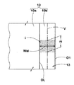
図1〜3は、それぞれ本実施形態のゴルフクラブヘッド(以下、単に「ヘッド」又は「クラブヘッド」ということがある。)1の基準状態の斜視図、平面図及び図2のX−X拡大断面図である。ここで、前記「基準状態」とは、クラブヘッド1のシャフト軸中心線を任意の垂直面VP内に配しかつ規定のライ角で傾けるとともに前記フェース2をロフト角αに保持して水平面HPに接地させた状態とする。
Hereinafter, an embodiment of the present invention will be described with reference to the drawings.
1 to 3 are respectively a perspective view, a plan view, and an XX enlarged view of FIG. 2 of a reference state of a golf club head (hereinafter, simply referred to as “head” or “club head”) 1 of the present embodiment. It is sectional drawing. Here, the “reference state” refers to a horizontal plane HP in which the shaft axis center line of the
前記ヘッド1は、ボールを打球する面であるフェース2を前面に有するフェース部3と、前記フェース2の上縁2aに連なりヘッド上面をなすクラウン部4と、前記フェース2の下縁2bに連なりヘッド底面をなすソール部5と、前記クラウン部4とソール部5との間を継ぎかつ前記フェース2のトウ側縁2cからバックフェースBFを通りヒール側縁2dに至ってのびるサイド部6と、クラウン部4のヒール側に設けられかつ図示しないシャフトが装着されるホーゼル部7とを具える。なお、クラブヘッド1にシャフトが装着されていない場合、前記ホーゼル部7のシャフト差込孔7aの軸中心線CLが、シャフト軸中心線として代用される。
The
前記ヘッド1は、図2及び図3に示されるように、内部に中空部iが設けられた中空構造を具え、好ましくはウッド型として構成される。なお、ウッド型のゴルフクラブヘッドとは、ヘッド材料が木質材からなるものという意味ではなく、従来、木質材で形成することが主流であったヘッド形状を有するものを指す。具体的には、少なくともドライバー(#1)、ブラッシー(#2)、スプーン(#3)、バフィ(#4)及びクリーク(#5)を含み、かつこれらとは番手ないし名称が異なるが、ほぼ類似した形状を持つヘッドをも含む概念である。
As shown in FIGS. 2 and 3, the
前記ヘッド1は、好ましくは80cm3 以上、より好ましくは90cm3 以上、さらに好ましくは100cm3以上の体積を有するのが望ましい。これにより、ヘッド1の慣性モーメントを大きくし、ミスショット時のヘッドのブレを最小限に抑え、打球の方向性を改善し得る。他方、ヘッド1の体積が大きすぎても、クラブ重量が増大して、例えばスイングバランスの悪化、ヘッドスピードの低下又は耐久性の低下を招くおそれがある。このような観点より、ヘッド1の体積は、好ましくは460cm3 以下が望ましい。
The
また、前記体積と同様の観点より、ヘッド1の重量は、好ましくは150g以上、より好ましくは160g以上、さらに好ましくは170g以上が望ましく、かつ、上限については、好ましくは300g以下、より好ましくは270g以下、さらに好ましくは250g以下が望ましい。
From the same viewpoint as the volume, the weight of the
また、前記ヘッド1は、クラウン部4に第1の開口部O1が、フェース部3に第2の開口部O2がそれぞれ設けられたヘッド本体1Aと、このヘッド本体1Aに固着されることにより前記第1の開口部O1を閉じるクラウン部材1Bと、前記ヘッド本体1Aに固着されることにより前記第2の開口部O2を閉じかつフェース部3の一部を構成するフェース部材1C(図3)と固着することにより形成される。
Further, the
本実施形態において、ヘッド本体1Aは、例えば比重が大きい金属材料で構成される一方、クラウン部材1B及びフェース部材1Cは、ともにヘッド本体1Aよりも比重が小さい材料で構成される。とりわけ、クラウン部材1Bをヘッド本体1Aに比して比重の小さい材料で構成することにより、ヘッド上部を軽量化でき、ひいては低いヘッド重心Gを提供しうる点で望ましい。
In the present embodiment, the head
特に限定されないが、前記ヘッド本体1Aの材料の比重ρ1は、好ましくは2.8以上、より好ましくは4.0以上、さらに好ましくは4.4以上が望ましい。これによって、ヘッドの低重心化及び慣性モーメントの増大に役立つ。他方、ヘッド重量やヘッド体積を考慮すると、前記比重は、好ましくは10.0以下、より好ましくは8.0以下、さらに好ましくは7.8以下が望ましい。このような材料としては、例えばステンレス合金やマレージング鋼などが好ましい。
Although not particularly limited, the specific gravity ρ1 of the material of the head
前記クラウン部材1Bの比重ρ2及びフェース部材1Cの比重ρ3は、特に限定されるものではないが、好ましくは1.0以上、より好ましくは1.8以上、さらに好ましくは2.8以上、最も好ましくは4.0が望ましい。比重ρ2又はρ3が1.0未満の材料では十分な強度が得られない傾向がある。他方、前記比重ρ2又はρ3が大きすぎると、クラウン部4において十分な重量削減効果が得られない傾向があるので、好ましくは8.0以下、より好ましくは7.9以下、さらに好ましくは5.0以下が望ましい。
The specific gravity ρ2 of the
このような材料としては、クラウン部材1Bには、繊維強化樹脂(比重約1.4)、チタン合金(比重約45)、アルミニウム合金(比重約2.7)又はマグネシウム合金(比重約1.8)などが好適である。また、ボールと直接接触するフェース部材1Cには、比強度の大きいTi−15V−6Cr−4Al、Ti−6Al−4V、Ti−13V−11Cr−3Al、Ti−5.5Al−1Fe、Ti−4.5Al−3V−2Fe−2Mo又はTi−4.5Al−2Mo−1.6V−0.5Feなどのチタン合金が望ましい。
As such a material, the
また、クラウン部材1Bの比重ρ2と、ヘッド本体1Aの比重ρ1との比(ρ2/ρ1)は、クラウン部4での十分な重量軽減を図りつつクラウン部材1Bの強度を確保するために、好ましくは0.20以上、より好ましくは0.30以上、さらに好ましくは0.50以上が望ましく、また、好ましくは0.80以下、より好ましくは0.75以下、さらに好ましくは0.70以下が望ましい。
Further, the ratio (ρ2 / ρ1) between the specific gravity ρ2 of the
本実施形態において、前記ヘッド本体1Aは、前記ソール部5、前記サイド部6、前記ホーゼル部7、前記クラウン部4において第1の開口部O1の周りに設けられたクラウン縁部10及び前記フェース部3において第2の開口部O2の周りに設けられたフェース縁部11が予め一体形成された鋳造品からなる。ただし、ヘッド本体1Aは、鍛造により又は圧延材を曲げ加工等することにより作られても良い。
In the present embodiment, the head
なお、クラウン部材1Bは、例えばヘッド本体1Aと同じ比重を有する金属材料で作られても良い。この場合、クラウン部材1Bに、ヘッド本体1Aよりも厚さが小さい材料、例えば圧延材等の薄板を用いることにより、ヘッド上部を軽量化することができる。即ち、湯流れ等を考慮すると、鋳造で作られるヘッド本体1Aは、そのクラウン部を薄肉化するには限界があるが、圧延材等を用いることにより、厚さが小さい(例えば1.0mm以下の)クラウン部材1Bを使用できる。
The
図2に示される平面視において、前記第1の開口部O1は、クラウン部4からはみ出すことなくその領域の中に収められる。これにより、クラウン縁部10は、第1の開口部O1の周りを環状に連続して形成される。同様に、第2の開口部O2も、フェース部3からはみ出すことなくその領域の中に収められる。これにより、フェース縁部11は、第2の開口部O2の周りに環状に連続して形成される。なお、前記第1の開口部O1、O2の形状は特に限定されないが、本実施形態のように、クラウン部4又はフェース部3の輪郭にほぼ沿った滑らかな輪郭形状を有するものが望ましい。
In the plan view shown in FIG. 2, the first opening O <b> 1 is accommodated in the region without protruding from the
図3に示されるように、前記フェース縁部11は、実質的にフェース2の外周部を形成する主部11aと、該主部11aからステップ状に凹むとともに前記フェース部材1Cの内面1Ciの周縁部を支える受け部11bとを含む。本実施形態では、受け部11bは、第2の開口部O2の周りに環状で連続して設けられる。なお、フェース縁部11とフェース部材1Cとは、例えば溶接、接着剤、ろう付け又は一部を塑性変形させたかしめなど種々の接合方法を用いて固着される。
As shown in FIG. 3, the
フェース部3の耐久性を向上させるために、該フェース部材1Cの厚さt4は、好ましくは1.5mm以上、より好ましくは2.0mm以上が望ましい。他方、フェース部3の重量を削減するためには、前記厚さt4は、好ましくは4.0mm以下、より好ましくは3.0mm以下が望ましい。本実施形態では、フェース部材1Cの厚さt4は、中央部で大きくかつ周辺部に向かって小さく形成されるが、一定厚さで形成されても良いのは言うまでもない。
In order to improve the durability of the
前記クラウン縁部10は、図4に拡大して示されるように、実質的にクラウン部4の仕上がり面4oを形成する主部10aと、該主部10aからステップ状に凹むとともに前記クラウン部材1Bの内面1Biの周縁部を支える受け部10bとを含む。前記クラウン部4の仕上がり面4oとは、塗膜等を除いて完成したヘッドの実質的な外表面であり、研磨処理等の削り代を含んでいても良い。また、クラウン部材1Bの内面1Biとは、該クラウン部材1Bの中空部i側を向く面である。
As shown in an enlarged view in FIG. 4, the
また、主部10aと受け部10bとの間には、クラウン部材1Bの外周面1Beに向き合う内壁面10aeが設けられる。該内壁面10aeは、クラウン部材1Bの外周面1Beの輪郭形状とほぼ近似するが、それよりも僅かに大きく形成される。従って、クラウン部材1Bをこの内壁面10aeに嵌め込むことができる。
In addition, an inner wall surface 10ae facing the outer peripheral surface 1Be of the
クラウン部4の耐久性を向上させるために、前記主部10aは、好ましくは0.3mm以上、より好ましくは0.4mm以上、さらに好ましくは0.8mm以上の厚さt1を有するものが好ましい。他方、該主部10aの厚さt1が大きくなると、クラウン部4の重量が大きくなる傾向がある。このような観点より、主部10aの厚さt1は、好ましくは2.0mm以下、より好ましくは1.5mm以下が望ましい。
In order to improve the durability of the
前記受け部10bは、クラウン部材1Bの厚さに応じ、主部10aの仕上がり面4oからのステップ量(凹み量)を最適化することにより、その上で支持されるクラウン部材1Bと前記主部10aとの面一な仕上げを可能とする。これは、後に研磨等による表面仕上げ工程を簡略化し、生産性を高めるのに役立つ。
The receiving
また、図5には、クラウン部材1Bを外したヘッド1の基準状態の平面図が示される。本実施形態において、受け部10bは、前側受け部13、中間受け部14及び後側受け部15の3つに仮想区分され、それらの平均幅が互いに関連付けて規定される。なお、ヘッド1に関して、前側とはフェース2側であり、後側とはバックフェースBF側を意味する。
FIG. 5 shows a plan view of the reference state of the
前記前側受け部13は、受け部10bのうち、第1の垂直面P1と第2の垂直面P2との間をのびる部分とする。ここで、第1の垂直面P1は、基準状態のヘッド1に対して、受け部10bの外縁10beがなす受け部輪郭OLの最も前側位置Aに接しかつ前記軸中心線CLと平行な垂直面とする。また、第2の垂直面P2は、前記第1の垂直面P1から、受け部輪郭OLのヘッド前後方向の最大長さLの1/4倍の距離をヘッド後方に隔てた垂直面とする。
The front receiving
また、前記「ヘッド前後方向」は、図2に示されるように、ヘッド重心Gからフェース2に立てた法線Nを水平面HPに投影して得られる直線と平行な方向FBとする。なお、前記法線Nとフェース2との交点SSは、スイートスポットである。
Further, as shown in FIG. 2, the “head longitudinal direction” is a direction FB parallel to a straight line obtained by projecting a normal line N raised from the center of gravity G of the head to the
また、前記中間受け部14は、受け部10bのうち、前記第2の垂直面P2と、前記第1の垂直面P1から受け部輪郭OLの前記最大長さLの3/4倍の距離を後方に隔てた第3の垂直面P3との間をのびる部分とする。この中間受け部14には、トウ側及びヒール側の双方に設けられる。
Further, the intermediate receiving
さらに、前記後側受け部15は、受け部10bのうち、前記第3の垂直面P3と、前記受け部輪郭OLの最も後側位置Bに接しかつ軸中心線CLと平行な第4の垂直面P4との間をのびる部分とする。
Further, the
そして、本発明では、これら前側受け部13の平均幅Waと、中間受け部14の平均幅Wbと、後側受け部の平均幅Wcとが、下記式(1)及び(2)を満たすことを特徴事項の一つとしている。
Wa>Wb …(1)
Wc>Wb …(2)
In the present invention, the average width Wa of the front receiving
Wa> Wb (1)
Wc> Wb (2)
発明者らは、ボール打撃時、受け部10bに生じる応力の分布を調べたところ、前側受け部13で最も大きく、次いで後側受け部15であり、中間受け部14では最も小さいことを知見した。従って、クラウン部材1Bとの接合強度と密に関連する受け部10bの幅に関し、上述の作用応力の分布に基づいて、中間受け部14の平均幅Wbを最も小さくすることにより、接合強度の低下を抑制しつつ受け部10bの重量を削減できる。他方、比較的大きな応力が生じる前側受け部13及び後側受け部15については、それらの平均幅Wa及びWcを、中間受け部14の平均幅Wbよりも大きくすることにより、クラウン部材1Bとの接合強度を高めて耐久性を維持しうる。
The inventors examined the distribution of stress generated in the receiving
とりわけ、下記式(3)のように、前記作用応力の分布により従うものとして、前側受け部13の平均幅Waを、後側受け部15の平均幅Wcよりも大きくすることが望ましい。
Wa>Wc …(3)
In particular, it is desirable that the average width Wa of the front
Wa> Wc (3)
ここで、各受け部13、14及び15の平均幅Wa、Wb及びWcは、周長さで重み付けされた加重平均の幅として得られる。例えば、前側受け部13の平均幅Waは、下記式(4)で計算することができる。
Wa=Σ(Wai・ni)/Σni (i=1,2…) …(4)
ここで、Waiは前側受け部13の任意の領域iの実幅、niは、前記実幅Waiの周長さとする。なお、図6に示されるように、受け部10bの実幅Waiは、受け部輪郭OLに対して法線方向に測定されるものとし、前記周長さは、実幅Waiの中心線V上で測定される。
Here, the average widths Wa, Wb and Wc of the receiving
Wa = Σ (Wai · ni) / Σni (i = 1, 2...) (4)
Here, Wa i is an actual width of an arbitrary region i of the front receiving
ここで、前記各平均幅Wa、Wb及びWcの具体的な値については、特に限定されるものではないが、小さすぎるとクラウン部材1Bとの接合強度が低下し、耐久性が悪化する傾向があり、逆に大きすぎると、ヘッド上部を効果的に軽量化することができないおそれがある。
Here, specific values of the average widths Wa, Wb, and Wc are not particularly limited. However, if the average widths Wa, Wb, and Wc are too small, the bonding strength with the
このような観点より、前側受け部13の平均幅Waは、好ましくは2.5mm以上、より好ましくは3.0mm以上、さらに好ましくは3.3mm以上が望ましく、また、好ましくは9.0mm以下、より好ましくは7.0mm以下、さらに好ましくは5.0mm以下の範囲で定められるのが望ましい。
From such a viewpoint, the average width Wa of the front receiving
同様に、中間受け部14の平均幅Wbは、好ましくは0.5mm以上、より好ましくは1.0mm以上、さらに好ましくは1.5mm以上が望ましく、また、好ましくは4.0mm以下、より好ましくは3.0mm以下、さらに好ましくは2.0mm以下の範囲で定められるのが望ましい。とりわけ、トウ側及びヒール側において、中間受け部14の平均幅Wbが実質的に等しいことが望ましい。
Similarly, the average width Wb of the intermediate receiving
さらに、後側受け部15の平均幅Wcは、好ましくは1.5mm以上、より好ましくは2.0mm以上、さらに好ましくは2.5mm以上が望ましく、また、好ましくは5.0mm以下、より好ましくは4.0mm以下、さらに好ましくは3.0mm以下の範囲で定められるのが望ましい。
Further, the average width Wc of the
なお、各受け部13ないし15は、図5に示されるように、鋭な段差等を有することなく滑らかに連続する態様が望ましい。また、各受け部13、14及び15の実幅も、それぞれの好ましい平均幅の数値範囲内であることが望ましい。
In addition, as shown in FIG. 5, it is desirable that each of the receiving
また、前側受け部13の平均幅Waと中間受け部14の平均幅Wbとの比(Wa/Wb)は、好ましくは1.2以上、より好ましくは1.5以上、さらに好ましくは1.7以上が望ましく、また、好ましくは6.0以下、より好ましくは4.0以下、さらに好ましくは3.0以下が望ましい。前記比(Wa/Wb)が小さくなると、前側受け部13と中間受け部14との平均幅の差が小さくなり、ひいては耐久性の悪化又はクラウン部の重量増加が生じるおそれがあり、逆に大きくなると、これらの境界部に応力が集中して耐久性が悪化するおそれがある。
Further, the ratio (Wa / Wb) between the average width Wa of the front receiving
同様に、後側受け部15の平均幅Wcと中間受け部14の平均幅Wbとの比(Wc/Wb)は、好ましくは1.1以上、より好ましくは1.3以上が望ましく、また、好ましくは3.0以下、より好ましくは2.0以下が望ましい。
Similarly, the ratio (Wc / Wb) of the average width Wc of the
さらに、前側受け部13の平均幅Waと後側受け部15の平均幅Wcとの比(Wa/Wc)は、好ましくは1.1以上、より好ましくは1.3以上が望ましく、また、好ましくは3.0以下、より好ましくは2.0以下が望ましい。
Further, the ratio (Wa / Wc) between the average width Wa of the front receiving
また、前記受け部10bの厚さt2は特に限定されないが、小さすぎると打球時の衝撃応力によって受け部10bに損傷が生じるおそれがある。このような観点より、前記厚さt2は、好ましくは0.2mm以上、より好ましくは0.3mm以上、さらに好ましくは0.5mm以上が望ましい。他方、この受け部10bの厚さt2が大きすぎると、クラウン部4の重量削減効果が低下するため、好ましくは前記主部10aの厚さt1以下とするのが望ましい。
Further, the thickness t2 of the receiving
また、クラウン部材1Bの厚さt3は、特に限定されないが、大きすぎるとクラウン部4の重量削減効果が十分に得られない傾向があり、逆に小さすぎると、ヘッド1の耐久性を低下させる傾向がある。このような観点より、クラウン部材1Bの厚さt3は、好ましくは0.3mm以上、より好ましくは0.4mm以上が望ましく、上限に関しては、好ましくは2.5mm以下、より好ましくは2.0mm以下が望ましい。なお、ソール部5の厚さt5は、クラウン部材1Bの厚さt3よりも大きいことが望ましく、例えば0.5mm以上、より好ましくは0.7mm以上、さらに好ましくは1.0mm以上が望ましい。他方、該ソール部5の厚さt5が大きくなると、ヘッド重量が増加するおそれがあるため、好ましくは5.5mm以下、より好ましくは5.0mm以下が望ましい。
Further, the thickness t3 of the
ヘッド本体1Aとクラウン部材1Bとの接合には、種々の方法が採用でき、例えば溶接、接着ロウ付け、摩擦圧接又はかしめ等の他、これらの1種若しくは2種以上を併用したものでも良い。
Various methods can be used for joining the head
また、前記基準状態において、ヘッド重心Gは、前記第2の垂直面P2と第3の垂直面P3との間に設けられるのが望ましい。本実施形態のクラブヘッド1は、前側受け部13の平均幅Wa及び後側受け部15の平均幅Wcが大きいので、その分だけヘッド重心Gを通りかつヘッド前後方向FBと直交する水平軸周りの慣性モーメントを大きくできる。これにより、フェース2のスイートスポットSSよりも上又は下で打撃した場合でも、ヘッドの前記水平軸周りのブレを抑制でき、ひいては弾道の上下のばらつきを低減しうる点で好ましい。なお、ヘッド重心Gの調整は、ヘッド本体1Aの各部の厚さの調整や、錘部材(図示省略)などによって行うことができる。
In the reference state, the center of gravity G of the head is preferably provided between the second vertical surface P2 and the third vertical surface P3. In the
また、十分な大きさの第1の開口部O1を確保するとともに、ヘッドの慣性モーメントを増大させるために、クラウン部4の面積Scは、好ましくは40cm2以上、より好ましくは45cm2以上、さらに好ましくは50cm2以上が望ましく、また、好ましくは100cm2以下、より好ましくは90cm2以下、さらに好ましくは80cm2以下が望ましい。ここで、クラウン部4の面積Scは、図2に示された基準状態の平面視において、フェース2の上縁2aと、サイド部6の輪郭線6aとで囲まれる領域の水平面HPへの投影面積とし、ホーゼル部7も含めるものとする。
Further, in order to secure the sufficiently large first opening O1 and increase the moment of inertia of the head, the area Sc of the
ここで、「フェース2の上縁2a」は、エッジ等によって外観上明りょうに特定できる場合にはそのエッジとするが、明りょうに特定できない場合には、図7(a)に示されるように、ヘッド1のスイートスポットSSとヘッド重心Gとを含む複数の平面E1、E2、E3における各断面図において、図7(b)に示されるようにフェース輪郭線Lfの曲率半径rをスイートスポットSSから上側に向かって順次求め、初めて200mmとなる位置Peを前記上縁2aとして定めることとする。
Here, the “
また、前記第1の開口部O1は、比重が小さいか又は薄板からなる軽量のクラウン部材1Bで閉じられるので、その面積に依存してクラウン部4の重量を削減させる。十分な低重心化を図るためには、クラウン部材1Bの面積Soは、好ましくは30cm2以上、より好ましくは35cm2以上、さらに好ましくは40cm2以上が望ましい。他方、クラウン部材1Bの面積が大きくなると、ヘッド本体1Aの剛性が過度に低下するおそれがあるので、該クラウン部材1Bの面積Soは、好ましくは80cm2以下、より好ましくは75cm2以下、さらに好ましくは70cm2以下が望ましい。なお、クラウン部材1Bの面積Soは、図3に示された基準状態の平面視において、水平面HPへ投影された面積とする。
Further, since the first opening O1 is closed by a
なお、クラウン部4の軽量化とヘッド本体1Aの剛性低下とをバランス良く発揮させるために、クラウン部材1Bの面積Soとクラウン部の面積Scとの比(So/Sc)は、好ましくは0.50以上、より好ましくは0.60以上、さらに好ましくは0.70以上が望ましく、また、好ましくは0.99以下、より好ましくは0.98以下、さらに好ましくは0.95以下が望ましい。
In order to achieve a good balance between reducing the weight of the
また、図5に示される基準状態の平面視において、クラブヘッド1の前後方向の最大長さFLは、好ましくは70mm以上、より好ましくは75mm以上、さらに好ましくは80mm以上が望ましく、また、好ましくは120mm以下、より好ましくは110mm以下、さらに好ましくは100mm以下が望ましい。該ヘッドの最大長さFLが小さくなると、前記水平軸周りの慣性モーメントが小さくなり、ひいては打球の高さが上下にぶれやすくなる傾向がある。逆に前記長さFLが小さくなると、ヘッドの投影面積が大きくなり、構えた際に違和感を生じやすくなる。
Further, in the plan view of the reference state shown in FIG. 5, the maximum length FL in the front-rear direction of the
同様に、図5に示される基準状態の平面視において、クラウン部4の前後方向の最大長さRLは、好ましくは50mm以上、より好ましくは55mm以上、さらに好ましくは60mm以上が望ましく、また、好ましくは100mm以下、より好ましくは95mm以下、さらに好ましくは90mm以下が望ましい。該クラウン部の最大長さRLが小さくなると、該クラウン部4に十分な大きさの開口部を設けることができない他、構えたときの安心感が損なわれる傾向があり、逆に大きすぎても構えた際に違和感を生じやすくなる。
Similarly, in the plan view of the reference state shown in FIG. 5, the maximum length RL in the front-rear direction of the
さらに、図5に示される基準状態の平面視において、前記受け部輪郭OLの前記最大長さLは、好ましくは30mm以上、より好ましくは40mm以上、さらに好ましくは50mm以上が望ましく、また、好ましくは80mm以下、より好ましくは70mm以下、さらに好ましくは60mm以下が望ましい。該受け部輪郭OLの最大長さLが小さくなると、開口面積が小さくなり、ヘッド上部の軽量化を十分に実現できないおそれがあり、逆に大きすぎると、ヘッド本体1Aの剛性を低下させるおそれがある。
Further, in the plan view of the reference state shown in FIG. 5, the maximum length L of the receiving portion contour OL is preferably 30 mm or more, more preferably 40 mm or more, further preferably 50 mm or more, and preferably 80 mm or less, more preferably 70 mm or less, and still more preferably 60 mm or less. If the maximum length L of the receiving portion contour OL is reduced, the opening area is reduced, and there is a possibility that the weight of the upper portion of the head cannot be sufficiently reduced. On the contrary, if it is too large, the rigidity of the head
以上、本発明の実施形態について、ウッド型のゴルフクラブヘッドを例に挙げ説明したが、本発明はこのような態様に限定されるものではなく、中空構造のものであれば、アイアン型、ユーティリティ型又はパター型などに適用することが可能である。 The embodiment of the present invention has been described by taking the wood type golf club head as an example. However, the present invention is not limited to such an embodiment. It is possible to apply to a mold or a putter mold.
表1の仕様に基づいて、ウッド型のゴルフクラブヘッドを試作した。共通仕様などは以下の通りである。
ヘッド体積:165cm3
ヘッド重量:200g
ロフト角:15度
ライ角:58度
ヘッド本体:SUS450(比重7.8)
フェース部材:Ti−4.5Al−3V−2Mo−2Fe(比重4.6)
クラウン部材:Ti−15V−3Cr−3Al−3Sn(比重4.8)
ヘッドの前後方向の最大長さFL:85mm
クラウン部の前後方向の長さRL:75mm
受け部輪郭の前後方向の最大長さL:60mm
クラウン部の面積Sc:65cm2
クラウン部材の面積So:58cm2
比(So/Sc)=0.89
また、テストの方法は、次の通りである。
Based on the specifications in Table 1, a wood-type golf club head was prototyped. The common specifications are as follows.
Head volume: 165cm 3
Head weight: 200g
Loft angle: 15 degrees Lie angle: 58 degrees Head body: SUS450 (specific gravity 7.8)
Face member: Ti-4.5Al-3V-2Mo-2Fe (specific gravity 4.6)
Crown member: Ti-15V-3Cr-3Al-3Sn (specific gravity 4.8)
Maximum length FL of head: 85mm
Crown length RL: 75mm
Maximum length L of the contour of the receiving part in the front-rear direction: 60mm
Crown area Sc: 65 cm 2
Crown member area So: 58 cm 2
Ratio (So / Sc) = 0.89
The test method is as follows.
<重心高さ>
前記基準状態において、水平面からスイートスポットSSまでの垂直高さである重心高さが測定された。小さいほど良好である。
<Height of center of gravity>
In the reference state, the height of the center of gravity, which is the vertical height from the horizontal plane to the sweet spot SS, was measured. Smaller is better.
<慣性モーメント>
基準状態においてヘッド重心を通る垂直軸周りの慣性モーメントが測定された。数値が大きいほど良好である。
<Inertia moment>
In the reference state, the moment of inertia about the vertical axis passing through the center of gravity of the head was measured. The larger the value, the better.
<耐久性>
各供試ヘッドにFRP製の同一のシャフト(SRIスポーツ株式会社製のMP300、フレックスR)を装着し45インチのウッド型ゴルフクラブが試作された。そして、各クラブをミヤマエ社製のスイングロボットに取り付け、フェースの中心かつヘッドスピード50m/sでゴルフボールを繰り返し打撃した。そして、100球毎にクラウン部材とヘッド本体との接合部の損傷の有無を調べ、該損傷が生じた打球数を調べた。結果は、比較例1の打球数を100とする指数であり、数値が大きいほど耐久性に優れていることを示す。
表1にテストの結果などを示す。
<Durability>
A 45-inch wood-type golf club was prototyped by mounting the same FRP shaft (MP300, Flex R, manufactured by SRI Sports Co., Ltd.) on each test head. Each club was attached to a swing robot manufactured by Miyamae Co., Ltd., and a golf ball was repeatedly hit with the center of the face and a head speed of 50 m / s. Then, every 100 balls were examined for damage at the joint between the crown member and the head body, and the number of hit balls in which the damage occurred was examined. A result is an index | exponent which makes the hit | ball hit number of the comparative example 1 100, and shows that it is excellent in durability, so that a numerical value is large.
Table 1 shows the test results.

テストの結果、実施例のヘッドは、耐久性を向上していることが確認できた。 As a result of the test, it was confirmed that the heads of the examples had improved durability.
1 ゴルフクラブヘッド
1A ヘッド本体
1B クラウン部材
1C フェース部材
2 フェース
3 フェース部
4 クラウン部
5 ソール部
6 サイド部
7 ホーゼル部
10b 受け部
13 前側受け部
14 中間受け部
15 後側受け部
G ヘッド重心
O1 第1の開口部
P1 第1の垂直面
P2 第2の垂直面
P3 第3の垂直面
P4 第4の垂直面
DESCRIPTION OF
Claims (4)
クラウン部に開口部が設けられたヘッド本体と、前記ヘッド本体に固着されることにより前記開口部を閉じるクラウン部材とを含み、かつ
前記開口部の周りには、前記クラウン部材の内面かつ周縁部を支える環状の受け部が設けられてなり、しかも
シャフト軸中心線を任意の垂直面内に配しかつ規定のライ角で傾けるとともに前記フェースをロフト角に保持して水平面に接地させた基準状態の平面視において、
前記受け部の外縁がなす受け部輪郭の最も前側位置に接しかつ前記シャフト軸中心線と平行な第1の垂直面と、該第1の垂直面から受け部輪郭のヘッド前後方向の最大長さの1/4倍の距離を後方に隔てる第2の垂直面との間をのびる前側受け部の平均幅Wa、
前記第2の垂直面と、前記第1の垂直面から受け部輪郭の前記最大長さの3/4倍の距離を後方に隔てる第3の垂直面との間をのびる中間受け部の平均幅Wb、及び
前記第3の垂直面と、前記受け部輪郭の最も後側位置に接しかつ前記シャフト軸中心線と平行な第4の垂直面との間をのびる後側受け部の平均幅Wcが下記式(1)及び(2)を満たすことを特徴とするゴルフクラブヘッド。
Wa>Wb …(1)
Wc>Wb …(2) A hollow golf club head having a face for hitting a ball,
A head body having an opening in the crown, and a crown member that closes the opening by being fixed to the head body, and an inner surface and a peripheral edge of the crown member around the opening A reference state in which an annular receiving portion is provided to support the shaft, and the shaft axis center line is arranged in an arbitrary vertical plane and tilted at a specified lie angle, and the face is held at a loft angle and grounded to a horizontal plane. In plan view of
A first vertical surface that is in contact with the frontmost position of the contour of the receiving portion formed by the outer edge of the receiving portion and is parallel to the shaft axis center line, and a maximum length in the head longitudinal direction of the receiving portion contour from the first vertical surface An average width Wa of the front receiving portion extending between the second vertical plane and a distance of 1/4 times the rear of the second vertical surface,
Average width of the intermediate receiving portion extending between the second vertical surface and a third vertical surface that is separated from the first vertical surface by a distance that is 3/4 times the maximum length of the receiving portion contour. Wb and an average width Wc of the rear receiving portion extending between the third vertical surface and a fourth vertical surface that is in contact with the rearmost position of the receiving portion contour and is parallel to the shaft axis center line. A golf club head satisfying the following formulas (1) and (2):
Wa> Wb (1)
Wc> Wb (2)
Wa>Wc …(3) The golf club head according to claim 1, wherein the following formula (3) is satisfied.
Wa> Wc (3)
Priority Applications (2)
| Application Number | Priority Date | Filing Date | Title |
|---|---|---|---|
| JP2007231765A JP5120878B2 (en) | 2007-09-06 | 2007-09-06 | Golf club head |
| US12/230,227 US7749103B2 (en) | 2007-09-06 | 2008-08-26 | Golf club head |
Applications Claiming Priority (1)
| Application Number | Priority Date | Filing Date | Title |
|---|---|---|---|
| JP2007231765A JP5120878B2 (en) | 2007-09-06 | 2007-09-06 | Golf club head |
Publications (2)
| Publication Number | Publication Date |
|---|---|
| JP2009061114A true JP2009061114A (en) | 2009-03-26 |
| JP5120878B2 JP5120878B2 (en) | 2013-01-16 |
Family
ID=40432464
Family Applications (1)
| Application Number | Title | Priority Date | Filing Date |
|---|---|---|---|
| JP2007231765A Active JP5120878B2 (en) | 2007-09-06 | 2007-09-06 | Golf club head |
Country Status (2)
| Country | Link |
|---|---|
| US (1) | US7749103B2 (en) |
| JP (1) | JP5120878B2 (en) |
Cited By (3)
| Publication number | Priority date | Publication date | Assignee | Title |
|---|---|---|---|---|
| JP2010259807A (en) * | 2009-05-08 | 2010-11-18 | Karsten Manufacturing Corp | Golf club head and method of manufacture |
| JP2012110429A (en) * | 2010-11-22 | 2012-06-14 | Sri Sports Ltd | Method of manufacturing golf club head |
| JP2013248180A (en) * | 2012-05-31 | 2013-12-12 | Dunlop Sports Co Ltd | Golf club head and method for manufacturing the same |
Families Citing this family (24)
| Publication number | Priority date | Publication date | Assignee | Title |
|---|---|---|---|---|
| US8715107B2 (en) * | 2009-11-04 | 2014-05-06 | Sri Sports Limited | Golf club head |
| JP5715520B2 (en) * | 2011-07-28 | 2015-05-07 | ダンロップスポーツ株式会社 | Golf club head and evaluation method thereof |
| US9079078B2 (en) | 2011-12-29 | 2015-07-14 | Taylor Made Golf Company, Inc. | Golf club head |
| US20160114229A1 (en) | 2014-10-24 | 2016-04-28 | Karsten Manufacturing Corporation | Golf club heads with energy storage characteristics |
| US9757630B2 (en) | 2015-05-20 | 2017-09-12 | Taylor Made Golf Company, Inc. | Golf club heads |
| US10016662B1 (en) | 2014-05-21 | 2018-07-10 | Taylor Made Golf Company, Inc. | Golf club |
| US10617918B2 (en) | 2014-08-26 | 2020-04-14 | Parsons Xtreme Golf, LLC | Golf club heads and methods to manufacture golf club heads |
| US9895583B2 (en) * | 2014-08-26 | 2018-02-20 | Parsons Xtreme Golf, LLC | Golf club heads and methods to manufacture golf club heads |
| US11344774B2 (en) | 2014-08-26 | 2022-05-31 | Parsons Xtreme Golf, LLC | Golf club heads and methods to manufacture golf club heads |
| US10898766B2 (en) | 2014-08-26 | 2021-01-26 | Parsons Xtreme Golf, LLC | Golf club heads and methods to manufacture golf club heads |
| US10420989B2 (en) | 2014-08-26 | 2019-09-24 | Parsons Xtreme Golf, LLC | Golf club heads and methods to manufacture golf club heads |
| US9399158B2 (en) * | 2014-08-26 | 2016-07-26 | Parsons Xtreme Golf, LLC | Golf club heads and methods to manufacture golf club heads |
| US20230014268A1 (en) * | 2014-10-24 | 2023-01-19 | Karsten Manufacturing Corporation | Golf club heads with energy storage characteristics |
| US10828543B2 (en) | 2016-05-27 | 2020-11-10 | Karsten Manufacturing Corporation | Mixed material golf club head |
| US10940373B2 (en) | 2016-05-27 | 2021-03-09 | Karsten Manufacturing Corporation | Mixed material golf club head |
| US10940374B2 (en) | 2016-05-27 | 2021-03-09 | Karsten Manufacturing Corporation | Mixed material golf club head |
| US9925432B2 (en) | 2016-05-27 | 2018-03-27 | Karsten Manufacturing Corporation | Mixed material golf club head |
| US11819743B2 (en) | 2016-05-27 | 2023-11-21 | Karsten Manufacturing Corporation | Mixed material golf club head |
| US10463927B2 (en) | 2016-12-06 | 2019-11-05 | Taylor Made Golf Company, Inc. | Golf club head |
| JP6809212B2 (en) * | 2016-12-27 | 2021-01-06 | 住友ゴム工業株式会社 | Golf club head |
| GB2576281B (en) * | 2017-05-05 | 2022-08-17 | Karsten Mfg Corp | Variable thickness face plate for a golf club head |
| GB2606475B (en) | 2018-01-19 | 2023-03-22 | Karsten Mfg Corp | Mixed material golf club head |
| US10806977B2 (en) | 2018-01-19 | 2020-10-20 | Karsten Manufacturing Corporation | Golf club heads comprising a thermoplastic composite material |
| US10583334B2 (en) | 2018-03-06 | 2020-03-10 | Acushnet Company | Golf club having a low modulus crown |
Citations (10)
| Publication number | Priority date | Publication date | Assignee | Title |
|---|---|---|---|---|
| JPH10248971A (en) * | 1997-03-07 | 1998-09-22 | Mizuno Corp | Iron club head |
| JP2003250935A (en) * | 2001-12-28 | 2003-09-09 | Yokohama Rubber Co Ltd:The | Hollow golf club head |
| JP2004041376A (en) * | 2002-07-10 | 2004-02-12 | Sumitomo Rubber Ind Ltd | Golf club head |
| JP2004167127A (en) * | 2002-11-22 | 2004-06-17 | Mizuno Corp | Metal golf club head and golf club |
| JP2004267765A (en) * | 2003-02-19 | 2004-09-30 | Yokohama Rubber Co Ltd:The | Simulation method of golf club head |
| JP2004305724A (en) * | 2003-03-27 | 2004-11-04 | Mizuno Corp | Golf club head and golf club |
| JP2005065774A (en) * | 2003-08-20 | 2005-03-17 | Sumitomo Rubber Ind Ltd | Manufacturing method for golf club head |
| JP2005287664A (en) * | 2004-03-31 | 2005-10-20 | Bridgestone Sports Co Ltd | Golf club head |
| JP2007117484A (en) * | 2005-10-28 | 2007-05-17 | Sri Sports Ltd | Golf club head |
| JP2007125242A (en) * | 2005-11-04 | 2007-05-24 | Sri Sports Ltd | Golf club head and its manufacturing method |
Family Cites Families (28)
| Publication number | Priority date | Publication date | Assignee | Title |
|---|---|---|---|---|
| US6575845B2 (en) * | 1999-11-01 | 2003-06-10 | Callaway Golf Company | Multiple material golf club head |
| US6663504B2 (en) * | 1999-11-01 | 2003-12-16 | Callaway Golf Company | Multiple material golf club head |
| JP4603187B2 (en) * | 2001-04-09 | 2010-12-22 | Sriスポーツ株式会社 | Golf club head |
| JP2003180885A (en) * | 2001-12-21 | 2003-07-02 | Sumitomo Rubber Ind Ltd | Golf club head and its production method |
| JP2004159854A (en) * | 2002-11-12 | 2004-06-10 | Mizuno Corp | Metal golf club head and golf club |
| TWI277435B (en) * | 2002-12-02 | 2007-04-01 | Mizuno Kk | Golf club head and method for producing the same |
| US6969326B2 (en) * | 2002-12-11 | 2005-11-29 | Taylor Made Golf Company, Inc. | Golf club head |
| TWI222375B (en) * | 2003-05-05 | 2004-10-21 | Fu Sheng Ind Co Ltd | Golf club head and manufacturing method therefor |
| JP2005058748A (en) * | 2003-07-31 | 2005-03-10 | Sumitomo Rubber Ind Ltd | Golf club head |
| JP4293531B2 (en) * | 2003-08-06 | 2009-07-08 | ダイワ精工株式会社 | Golf club head |
| JP4202888B2 (en) * | 2003-10-23 | 2008-12-24 | Sriスポーツ株式会社 | Golf club head |
| JP4287769B2 (en) * | 2004-03-17 | 2009-07-01 | Sriスポーツ株式会社 | Golf club head and manufacturing method thereof |
| US7189165B2 (en) * | 2004-03-18 | 2007-03-13 | Sri Sports Limited | Golf club head |
| JP2005270215A (en) * | 2004-03-23 | 2005-10-06 | Sri Sports Ltd | Golf club head |
| JP4355245B2 (en) * | 2004-03-24 | 2009-10-28 | Sriスポーツ株式会社 | Golf club head |
| JP4335064B2 (en) * | 2004-04-20 | 2009-09-30 | Sriスポーツ株式会社 | Golf club head |
| JP4410606B2 (en) * | 2004-06-03 | 2010-02-03 | Sriスポーツ株式会社 | Golf club head |
| JP2006020817A (en) * | 2004-07-07 | 2006-01-26 | Fu Sheng Industrial Co Ltd | Assembly structure of golf club head |
| JP4482387B2 (en) * | 2004-07-13 | 2010-06-16 | Sriスポーツ株式会社 | Golf club head |
| US7175541B2 (en) * | 2004-07-20 | 2007-02-13 | Fu Sheng Industrial Co., Ltd. | Golf club head |
| US7059973B2 (en) * | 2004-09-10 | 2006-06-13 | Callaway Golf Company | Multiple material golf club head |
| US7066835B2 (en) * | 2004-09-10 | 2006-06-27 | Callaway Golf Company | Multiple material golf club head |
| TWI259777B (en) * | 2005-03-03 | 2006-08-11 | Fu Sheng Ind Co Ltd | Welding structure for golf club head and manufacturing method therefor |
| US7452287B2 (en) * | 2005-03-18 | 2008-11-18 | Callaway Golf Company | Multiple material golf club head |
| US7559853B2 (en) * | 2005-06-20 | 2009-07-14 | Sri Sports Limited | Golf club head and method for manufacturing the same |
| JP2007125243A (en) * | 2005-11-04 | 2007-05-24 | Sri Sports Ltd | Golf club head |
| KR100645254B1 (en) * | 2006-06-19 | 2006-11-15 | 정지영 | Golf club |
| JP2009247399A (en) * | 2008-04-01 | 2009-10-29 | Sri Sports Ltd | Golf club set |
-
2007
- 2007-09-06 JP JP2007231765A patent/JP5120878B2/en active Active
-
2008
- 2008-08-26 US US12/230,227 patent/US7749103B2/en active Active
Patent Citations (10)
| Publication number | Priority date | Publication date | Assignee | Title |
|---|---|---|---|---|
| JPH10248971A (en) * | 1997-03-07 | 1998-09-22 | Mizuno Corp | Iron club head |
| JP2003250935A (en) * | 2001-12-28 | 2003-09-09 | Yokohama Rubber Co Ltd:The | Hollow golf club head |
| JP2004041376A (en) * | 2002-07-10 | 2004-02-12 | Sumitomo Rubber Ind Ltd | Golf club head |
| JP2004167127A (en) * | 2002-11-22 | 2004-06-17 | Mizuno Corp | Metal golf club head and golf club |
| JP2004267765A (en) * | 2003-02-19 | 2004-09-30 | Yokohama Rubber Co Ltd:The | Simulation method of golf club head |
| JP2004305724A (en) * | 2003-03-27 | 2004-11-04 | Mizuno Corp | Golf club head and golf club |
| JP2005065774A (en) * | 2003-08-20 | 2005-03-17 | Sumitomo Rubber Ind Ltd | Manufacturing method for golf club head |
| JP2005287664A (en) * | 2004-03-31 | 2005-10-20 | Bridgestone Sports Co Ltd | Golf club head |
| JP2007117484A (en) * | 2005-10-28 | 2007-05-17 | Sri Sports Ltd | Golf club head |
| JP2007125242A (en) * | 2005-11-04 | 2007-05-24 | Sri Sports Ltd | Golf club head and its manufacturing method |
Cited By (3)
| Publication number | Priority date | Publication date | Assignee | Title |
|---|---|---|---|---|
| JP2010259807A (en) * | 2009-05-08 | 2010-11-18 | Karsten Manufacturing Corp | Golf club head and method of manufacture |
| JP2012110429A (en) * | 2010-11-22 | 2012-06-14 | Sri Sports Ltd | Method of manufacturing golf club head |
| JP2013248180A (en) * | 2012-05-31 | 2013-12-12 | Dunlop Sports Co Ltd | Golf club head and method for manufacturing the same |
Also Published As
| Publication number | Publication date |
|---|---|
| US20090069113A1 (en) | 2009-03-12 |
| JP5120878B2 (en) | 2013-01-16 |
| US7749103B2 (en) | 2010-07-06 |
Similar Documents
| Publication | Publication Date | Title |
|---|---|---|
| JP5120878B2 (en) | Golf club head | |
| JP4612526B2 (en) | Golf club head | |
| JP5135783B2 (en) | Golf club head | |
| JP4674866B2 (en) | Golf club head | |
| JP6790352B2 (en) | Golf club head | |
| JP4378298B2 (en) | Golf club head | |
| US7559853B2 (en) | Golf club head and method for manufacturing the same | |
| JP4410606B2 (en) | Golf club head | |
| JP4326559B2 (en) | Golf club head | |
| US7993214B2 (en) | Golf club head | |
| JP5174129B2 (en) | Golf club head | |
| JP5028941B2 (en) | Golf club head | |
| US20070287552A1 (en) | Hollow metal golf club head and method for manufacturing the same | |
| JP5756305B2 (en) | Golf club head and golf club using the same | |
| JP2010273804A (en) | Golf club head | |
| JP2005143601A (en) | Golf club head | |
| JP2004222792A (en) | Golf club head | |
| JP2008253564A (en) | Golf club head | |
| US9889348B2 (en) | Golf club head | |
| JP2008183037A (en) | Golf club head | |
| JP2009273579A (en) | Golf club head and method for manufacturing the same | |
| JP2010029358A (en) | Golf club head | |
| JP5095687B2 (en) | Golf club head | |
| JP2009247399A (en) | Golf club set | |
| JP2008093268A (en) | Golf club head |
Legal Events
| Date | Code | Title | Description |
|---|---|---|---|
| A621 | Written request for application examination |
Free format text: JAPANESE INTERMEDIATE CODE: A621 Effective date: 20100316 |
|
| A977 | Report on retrieval |
Free format text: JAPANESE INTERMEDIATE CODE: A971007 Effective date: 20111110 |
|
| A131 | Notification of reasons for refusal |
Free format text: JAPANESE INTERMEDIATE CODE: A131 Effective date: 20111115 |
|
| A521 | Request for written amendment filed |
Free format text: JAPANESE INTERMEDIATE CODE: A523 Effective date: 20111229 |
|
| TRDD | Decision of grant or rejection written | ||
| A01 | Written decision to grant a patent or to grant a registration (utility model) |
Free format text: JAPANESE INTERMEDIATE CODE: A01 Effective date: 20120918 |
|
| A01 | Written decision to grant a patent or to grant a registration (utility model) |
Free format text: JAPANESE INTERMEDIATE CODE: A01 |
|
| A61 | First payment of annual fees (during grant procedure) |
Free format text: JAPANESE INTERMEDIATE CODE: A61 Effective date: 20120928 |
|
| A61 | First payment of annual fees (during grant procedure) |
Free format text: JAPANESE INTERMEDIATE CODE: A61 Effective date: 20121017 |
|
| FPAY | Renewal fee payment (event date is renewal date of database) |
Free format text: PAYMENT UNTIL: 20151102 Year of fee payment: 3 |
|
| R150 | Certificate of patent or registration of utility model |
Free format text: JAPANESE INTERMEDIATE CODE: R150 Ref document number: 5120878 Country of ref document: JP Free format text: JAPANESE INTERMEDIATE CODE: R150 |
|
| FPAY | Renewal fee payment (event date is renewal date of database) |
Free format text: PAYMENT UNTIL: 20151102 Year of fee payment: 3 |
|
| R250 | Receipt of annual fees |
Free format text: JAPANESE INTERMEDIATE CODE: R250 |
|
| R250 | Receipt of annual fees |
Free format text: JAPANESE INTERMEDIATE CODE: R250 |
|
| R250 | Receipt of annual fees |
Free format text: JAPANESE INTERMEDIATE CODE: R250 |
|
| R250 | Receipt of annual fees |
Free format text: JAPANESE INTERMEDIATE CODE: R250 |
|
| R250 | Receipt of annual fees |
Free format text: JAPANESE INTERMEDIATE CODE: R250 |
|
| R250 | Receipt of annual fees |
Free format text: JAPANESE INTERMEDIATE CODE: R250 |
|
| R250 | Receipt of annual fees |
Free format text: JAPANESE INTERMEDIATE CODE: R250 |
|
| R250 | Receipt of annual fees |
Free format text: JAPANESE INTERMEDIATE CODE: R250 |
|
| R250 | Receipt of annual fees |
Free format text: JAPANESE INTERMEDIATE CODE: R250 |