JP2009059448A - Laser diode control method, laser diode control device, and information recording and reproducing device - Google Patents
Laser diode control method, laser diode control device, and information recording and reproducing device Download PDFInfo
- Publication number
- JP2009059448A JP2009059448A JP2007227679A JP2007227679A JP2009059448A JP 2009059448 A JP2009059448 A JP 2009059448A JP 2007227679 A JP2007227679 A JP 2007227679A JP 2007227679 A JP2007227679 A JP 2007227679A JP 2009059448 A JP2009059448 A JP 2009059448A
- Authority
- JP
- Japan
- Prior art keywords
- laser diode
- pickup
- temperature
- recording
- recording medium
- Prior art date
- Legal status (The legal status is an assumption and is not a legal conclusion. Google has not performed a legal analysis and makes no representation as to the accuracy of the status listed.)
- Granted
Links
Images


Classifications
-
- H—ELECTRICITY
- H01—ELECTRIC ELEMENTS
- H01S—DEVICES USING THE PROCESS OF LIGHT AMPLIFICATION BY STIMULATED EMISSION OF RADIATION [LASER] TO AMPLIFY OR GENERATE LIGHT; DEVICES USING STIMULATED EMISSION OF ELECTROMAGNETIC RADIATION IN WAVE RANGES OTHER THAN OPTICAL
- H01S5/00—Semiconductor lasers
- H01S5/06—Arrangements for controlling the laser output parameters, e.g. by operating on the active medium
- H01S5/068—Stabilisation of laser output parameters
- H01S5/06804—Stabilisation of laser output parameters by monitoring an external parameter, e.g. temperature
-
- G—PHYSICS
- G11—INFORMATION STORAGE
- G11B—INFORMATION STORAGE BASED ON RELATIVE MOVEMENT BETWEEN RECORD CARRIER AND TRANSDUCER
- G11B19/00—Driving, starting, stopping record carriers not specifically of filamentary or web form, or of supports therefor; Control thereof; Control of operating function ; Driving both disc and head
- G11B19/20—Driving; Starting; Stopping; Control thereof
- G11B19/2054—Spindle motor power-up sequences
-
- G—PHYSICS
- G11—INFORMATION STORAGE
- G11B—INFORMATION STORAGE BASED ON RELATIVE MOVEMENT BETWEEN RECORD CARRIER AND TRANSDUCER
- G11B7/00—Recording or reproducing by optical means, e.g. recording using a thermal beam of optical radiation by modifying optical properties or the physical structure, reproducing using an optical beam at lower power by sensing optical properties; Record carriers therefor
- G11B7/12—Heads, e.g. forming of the optical beam spot or modulation of the optical beam
- G11B7/125—Optical beam sources therefor, e.g. laser control circuitry specially adapted for optical storage devices; Modulators, e.g. means for controlling the size or intensity of optical spots or optical traces
- G11B7/126—Circuits, methods or arrangements for laser control or stabilisation
-
- G—PHYSICS
- G11—INFORMATION STORAGE
- G11B—INFORMATION STORAGE BASED ON RELATIVE MOVEMENT BETWEEN RECORD CARRIER AND TRANSDUCER
- G11B7/00—Recording or reproducing by optical means, e.g. recording using a thermal beam of optical radiation by modifying optical properties or the physical structure, reproducing using an optical beam at lower power by sensing optical properties; Record carriers therefor
- G11B7/004—Recording, reproducing or erasing methods; Read, write or erase circuits therefor
- G11B7/0045—Recording
-
- G—PHYSICS
- G11—INFORMATION STORAGE
- G11B—INFORMATION STORAGE BASED ON RELATIVE MOVEMENT BETWEEN RECORD CARRIER AND TRANSDUCER
- G11B7/00—Recording or reproducing by optical means, e.g. recording using a thermal beam of optical radiation by modifying optical properties or the physical structure, reproducing using an optical beam at lower power by sensing optical properties; Record carriers therefor
- G11B7/08—Disposition or mounting of heads or light sources relatively to record carriers
- G11B7/085—Disposition or mounting of heads or light sources relatively to record carriers with provision for moving the light beam into, or out of, its operative position or across tracks, otherwise than during the transducing operation, e.g. for adjustment or preliminary positioning or track change or selection
- G11B7/08505—Methods for track change, selection or preliminary positioning by moving the head
Abstract
Description
本発明は、情報記録再生装置に関し、特にカムコーダに使用する光ディスク装置の書込み若しくは読出しに使用するレーザダイオードの制御に関する。 The present invention relates to an information recording / reproducing apparatus, and more particularly to control of a laser diode used for writing or reading of an optical disk apparatus used for a camcorder.
光ディスク装置を記録媒体としたビデオカメラが製品化されて久しい。また、光ディスク装置自体も、CD( Compact Disc )、DVD( Digital Versatile Disc )から、HD DVD( High Definition DVD )、Blu−ray Disc(ブルーレイディスク:BD)といった次世代DVDへと進んできつつある。次世代DVDでは、記録容量が従来のDVDに比べて3倍〜5倍以上となり、近年のPDP( Plasma Display Panel )等の発展により益々高画質映像の要求が高まる中、高画質映像に伴うデータ量の増加に対応できる記録媒体として脚光を浴びつつある。 It has been a long time since a video camera using an optical disk device as a recording medium was commercialized. In addition, the optical disc apparatus itself is progressing from CD (Compact Disc) and DVD (Digital Versatile Disc) to next-generation DVD such as HD DVD (High Definition DVD) and Blu-ray Disc (Blu-ray Disc: BD). In the next-generation DVD, the recording capacity is 3 to 5 times that of the conventional DVD, and the demand for high-quality video is increasing due to the recent development of PDP (Plasma Display Panel) and the like. It is attracting attention as a recording medium that can cope with the increase in volume.
光ディスク装置において、記録容量の増大に必要な要素の1つとして、単位面積あたりの記録容量の増加が挙げられる。このためには、データを書込むため若しくは読出すために光ディスクに照射するレーザ光の直径(レーザ光径)を小さくすることが必要になってくる。レーザ光径を小さくするためには、単純には、書込み若しくは読出しに使用するレーザ光の波長を短くすれば良い。
現在、レーザダイオード(LD)光源としては、青紫色レーザダイオードから出力される光の波長が一番短い。青紫色レーザダイオードの光ディスク装置を使用した製品としては、PC( Personal Computer )の他、ゲーム機若しくはビデオレコーダ等がある。レーザダイオードを用いた装置としては、その他にレーザビーム画像形成装置がある。
In an optical disk device, one of the elements necessary for increasing the recording capacity is an increase in recording capacity per unit area. For this purpose, it is necessary to reduce the diameter (laser beam diameter) of the laser beam applied to the optical disk in order to write or read data. In order to reduce the laser beam diameter, the wavelength of the laser beam used for writing or reading can be simply shortened.
Currently, the wavelength of light output from a blue-violet laser diode is the shortest as a laser diode (LD) light source. As a product using a blue-violet laser diode optical disk device, there is a game machine or a video recorder in addition to a PC (Personal Computer). As another apparatus using a laser diode, there is a laser beam image forming apparatus.
上述したような光ディスク装置若しくは光ディスク装置を使用した装置において、レーザダイオードの温度が外気温度より低い場合には、レーザダイオードの出力面に水滴を生じることがあり、水滴によってレーザビームのエネルギーが熱エネルギーに変換されレンズ等が破壊する恐れがある。これを防ぐために、特許文献1若しくは特許文献2において、結露若しくは所定の温度より低い場合にはしきい値以下の電流を流し結露が消滅してからレーザ光を出力している(特許文献1若しくは特許文献2参照。)。
また、カムコーダに使用する光ディスク装置のレーザダイオード結露対策に関しては、結露の誤検出を少なくして撮影チャンスを逃さないようにする技術の一例が特許文献3に記載されている。
In the optical disk apparatus or the apparatus using the optical disk apparatus as described above, when the temperature of the laser diode is lower than the outside air temperature, water droplets may be generated on the output surface of the laser diode, and the energy of the laser beam is caused by the water droplets as thermal energy. There is a risk that the lens will be destroyed. In order to prevent this, in
In addition, as a countermeasure against the laser diode dew condensation of the optical disk device used in the camcorder,
しかしながら、青紫色レーザダイオード等、短波長のレーザダイオードは、それより長い波長他の色のレーザダイオードに比べて、動作保証温度範囲が狭く、低温になると動作しないか、または、低温キンク現象やレーザ光強度立上がりの長時間化が起きることがある。低温キンク現象とは、温度をパラメータとしてレーザダイオードに流す電流を横軸にとり、縦軸にレーザ光の出力をとったときに、電流−レーザパワーの線形性が崩れる現象である。レーザ光強度立上がりの長時間化とは、レーザダイオードに電流を供給したときにレーザダイオードから発光されるレーザ光が所定の強度になるまでの時間が長くなってしまう現象である。
従って、室内で使用する機器では問題ないが、屋外の寒冷地でも使うカムコーダやポータブルBDプレイヤ等では、記録(書込み)や読み出しができないという問題が起きる。
However, short-wavelength laser diodes such as blue-violet laser diodes have a narrower guaranteed operating temperature range than laser diodes of longer wavelengths and other colors, and do not operate at low temperatures, Longer light intensity rise may occur. The low-temperature kink phenomenon is a phenomenon in which the current-laser power linearity is lost when the current flowing through the laser diode is plotted on the horizontal axis and the laser beam output is plotted on the vertical axis. The lengthening of the rise of the laser beam intensity is a phenomenon in which it takes a long time for the laser beam emitted from the laser diode to have a predetermined intensity when a current is supplied to the laser diode.
Therefore, although there is no problem with a device used indoors, there is a problem that recording (writing) or reading cannot be performed with a camcorder, a portable BD player, or the like that is used even in an outdoor cold region.
図1は、レーザダイオード(LD)の温度が25℃の時の供給電流Iと出力レーザパワーLとの関係(I−L特性)の一例を示す図である。横軸は、レーザダイオードに供給する電流値(単位:[mA])、縦軸は、供給された電流値に対応するレーザ光出力のレーザパワー(単位:[mW])である。
図1において、Ithはしきい値電流、Iscは許容最大電流である。供給電流Iが小さくしきい値電流Ithまで((A)の領域)は、レーザ光は出力されない。そして、しきい値電流Ithを超えるとレーザ光が出力され、線形性を保って、供給電流が増えるにつれてレーザパワーも増大していく。その後、最大許容電流Iscに達すると、これ以上レーザダイオードに電流を流せないためレーザ光出力はこれ以上上がらない((B)の領域)。
FIG. 1 is a diagram showing an example of the relationship (IL characteristic) between the supply current I and the output laser power L when the temperature of the laser diode (LD) is 25 ° C. The horizontal axis represents the current value (unit: [mA]) supplied to the laser diode, and the vertical axis represents the laser power (unit: [mW]) of the laser beam output corresponding to the supplied current value.
In FIG. 1, Ith is a threshold current, and Isc is an allowable maximum current. The laser beam is not output until the supply current I is small and reaches the threshold current Ith (region (A)). When the threshold current Ith is exceeded, laser light is output, maintaining linearity, and the laser power increases as the supply current increases. Thereafter, when the maximum allowable current Isc is reached, no more current can flow through the laser diode, so the laser light output does not increase any more (region (B)).
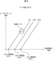
図2によって、レーザダイオードの温度特性を説明する。図2は、レーザダイオードの温度(0℃、10℃、20℃)をパラメータとしたときの供給電流Iと出力レーザパワーLの関係の一例を示す図である。
図2に示すように、レーザダイオードの温度は0℃、10℃、及び20℃の特性において、温度が上がるにつれて、供給電流に対するレーザパワーが小さくなる。また、しきい値電流も温度が高くなるにつれて増大する傾向である。
更に、0℃では途中で線形性(リニアリティ)が失われている。このように、低温で線形性が失われる現象を低温キンクと呼ぶ。低温キンクが発生する温度では、線形性がないので、動作保証温度範囲外として、一般的に、レーザダイオードは使用できないので、光ディスク装置は書込み(記録)若しくは読出し(再生)ができない。
他の問題として、レーザダイオードの温度が動作保証温度に上昇したとしても、レーザ光が出力されるまでの立上がり時間は、低温であるほど長くなる傾向がある。
このため、レーザダイオードの温度が低い場合には、書込み若しくは読出しに必要なレーザパワーに達しないまま書込み若しくは読出しを行うことも考えられる。この場合、書込み品質の劣化や読出しエラー(ミスリード)が発生する可能性がある。
The temperature characteristics of the laser diode will be described with reference to FIG. FIG. 2 is a diagram showing an example of the relationship between the supply current I and the output laser power L when the temperature of the laser diode (0 ° C., 10 ° C., 20 ° C.) is used as a parameter.
As shown in FIG. 2, the laser diode temperature is 0 ° C., 10 ° C., and 20 ° C. As the temperature increases, the laser power with respect to the supply current decreases. The threshold current also tends to increase as the temperature increases.
Further, at 0 ° C., the linearity is lost in the middle. Such a phenomenon that the linearity is lost at a low temperature is called a low-temperature kink. Since there is no linearity at a temperature at which a low-temperature kink occurs, the laser diode is generally not usable outside the guaranteed operating temperature range, so that the optical disk apparatus cannot be written (recorded) or read (reproduced).
As another problem, even if the temperature of the laser diode rises to the operation guarantee temperature, the rise time until the laser beam is output tends to become longer as the temperature is lower.
For this reason, when the temperature of the laser diode is low, writing or reading may be performed without reaching the laser power necessary for writing or reading. In this case, there is a possibility that the write quality is deteriorated or a read error (misread) occurs.
従来技術の特許文献1及び特許文献2は、レーザダイオード駆動制御装置に冷却器が備えられた機器について、レーザ光出力によってレーザダイオードが高温になり出力効率が落ちることを防ぐために冷却する場合に、冷却しすぎる問題を解決するための技術である。特に、特許文献1は、結露対策に関わり、また特許文献2は、冷却器が機能しない低い温度では温度制御ができないので、レーザ光を出力が変動するのでしきい値以下の電流を流して基準温度範囲内で駆動させる技術である。
特許文献3のカムコーダに内蔵される光ディスク装置での結露は、光ディスク装置が冷たくてレーザダイオード自体が周囲温度よりも低温状態のときに、周囲の雰囲気中の水分がレーザダイオードに付着する現象である。換言すれば、レーザダイオードの温度がレーザダイオードの動作保証温度より高くなった時に強制的に冷却を行い、レーザダイオードだけ周囲温度より低温の状態を作るので、結露の発生を必然的に伴う。従って、特許文献3の現象は、結露対策を目的とする特許文献1はもとより、冷却器を備える特許文献2の技術にも結露が必然的に発生する。
Condensation in the optical disk device built in the camcorder of
いずれにしても、従来技術の特許文献1、特許文献2、若しくは特許文献3による問題は、本願発明にあるような、低温キンク現象が発生するような、即ち、レーザダイオードの動作保証温度以下の温度での問題や、レーザダイオードの動作保証温度内ではあるけれどもレーザ光強度立上がりの長時間化の問題とは異なる。
本発明の目的は、上記のような問題を解決し、情報の記録または再生を適切に行うレーザダイオードの制御方法及び制御装置並びにカムコーダ等の情報記録再生装置を提供することにある。
In any case, the problem according to
SUMMARY OF THE INVENTION An object of the present invention is to solve the above problems and to provide a laser diode control method and control apparatus for appropriately recording or reproducing information and an information recording / reproducing apparatus such as a camcorder.
上記の目的を達成するために、本発明のレーザダイオード制御装置のレーザダイオード制御方法は、
レーザダイオードと、
レーザダイオードに電流を供給してレーザダイオードを駆動する駆動装置と、
レーザダイオード、対物レンズなどの光学部品、これらを納めるケースなどから構成されるピックアップと、
対物レンズの焦点位置を変更する対物レンズ移動手段と、
ピックアップを所定の照射位置に移動するピックアップ移動手段と、
レーザダイオードの近傍の温度を検出する温度センサと、
制御部とを備えたレーザダイオード制御装置のレーザダイオード制御方法であって、
制御部の制御により、温度センサの検出する温度が所定値以下であった場合には、ピックアップ移動手段を制御してピックアップを記録媒体の記録領域外に移動し、
駆動装置を制御してしきい値を超える電流をレーザダイオードに供給してレーザ光を出力することによってレーザダイオードの温度を上昇させることを特徴とする。
In order to achieve the above object, the laser diode control method of the laser diode control device of the present invention comprises:
A laser diode;
A driving device for driving the laser diode by supplying current to the laser diode;
A pickup composed of optical components such as a laser diode and an objective lens, and a case for housing them;
Objective lens moving means for changing the focal position of the objective lens;
Pickup moving means for moving the pickup to a predetermined irradiation position;
A temperature sensor for detecting the temperature in the vicinity of the laser diode;
A laser diode control method of a laser diode control device comprising a control unit,
When the temperature detected by the temperature sensor is below a predetermined value by the control of the control unit, the pickup moving means is controlled to move the pickup out of the recording area of the recording medium,
The temperature of the laser diode is raised by controlling the driving device to supply a current exceeding the threshold value to the laser diode to output laser light.
また、本発明のレーザダイオード制御装置のレーザダイオード制御方法は、
レーザダイオードと、
レーザダイオードに電流を供給してレーザダイオードを駆動する駆動装置と、
レーザダイオード、対物レンズなどの光学部品、これらを納めるケースなどから構成されるピックアップと、
対物レンズの焦点位置を変更する対物レンズ移動手段と、
ピックアップを所定の照射位置に移動するピックアップ移動手段と、
レーザダイオードの近傍の温度を検出する温度センサと、
制御部とを備えたレーザダイオード制御装置のレーザダイオード制御方法であって、
制御部の制御により、温度センサの検出する温度が所定値以下であった場合には、対物レンズ移動手段を制御して記録媒体に照射するレーザ光の焦点位置を記録媒体の記録膜外の位置に設定し、
駆動装置を制御してしきい値を超える電流をレーザダイオードに供給してレーザ光を出力することによってレーザダイオードの温度を上昇させることを特徴とする。
Further, the laser diode control method of the laser diode control device of the present invention,
A laser diode;
A driving device for driving the laser diode by supplying current to the laser diode;
A pickup composed of optical components such as a laser diode and an objective lens, and a case for housing them;
Objective lens moving means for changing the focal position of the objective lens;
Pickup moving means for moving the pickup to a predetermined irradiation position;
A temperature sensor for detecting the temperature in the vicinity of the laser diode;
A laser diode control method of a laser diode control device comprising a control unit,
When the temperature detected by the temperature sensor is equal to or lower than a predetermined value under the control of the control unit, the focal position of the laser beam irradiated to the recording medium by controlling the objective lens moving means is set to a position outside the recording film of the recording medium. Set to
The temperature of the laser diode is raised by controlling the driving device to supply a current exceeding the threshold value to the laser diode to output laser light.
また、本発明のレーザダイオード制御装置のレーザダイオード制御方法は、
レーザダイオードと、
レーザダイオードに電流を供給してレーザダイオードを駆動する駆動装置と、
レーザダイオード、対物レンズなどの光学部品、これらを納めるケースなどから構成されるピックアップと、
対物レンズの焦点位置を変更する対物レンズ移動手段と、
ピックアップを所定の照射位置に移動するピックアップ移動手段と、
レーザダイオードの近傍の温度を検出する温度センサと、
制御部とを備えたレーザダイオード制御装置のレーザダイオード制御方法であって、
制御部の制御により、温度センサの検出する温度が所定値以下で、ピックアップの照射位置が記録媒体上の記録領域内にある場合には、対物レンズ移動手段を制御して記録媒体に照射するレーザ光の焦点位置を記録媒体の記録膜外の位置に設定し、
かつピックアップ移動手段を制御してピックアップを記録媒体の記録領域外に移動しつつ、
駆動装置を制御してしきい値を超える電流をレーザダイオードに供給してレーザ光を出力することによってレーザダイオードの温度を上昇させることを特徴とする。
Further, the laser diode control method of the laser diode control device of the present invention,
A laser diode;
A driving device for driving the laser diode by supplying current to the laser diode;
A pickup composed of optical components such as a laser diode and an objective lens, and a case for housing them;
Objective lens moving means for changing the focal position of the objective lens;
Pickup moving means for moving the pickup to a predetermined irradiation position;
A temperature sensor for detecting the temperature in the vicinity of the laser diode;
A laser diode control method of a laser diode control device comprising a control unit,
A laser that irradiates the recording medium by controlling the objective lens moving means when the temperature detected by the temperature sensor is below a predetermined value and the irradiation position of the pickup is within the recording area on the recording medium under the control of the control unit. Set the focal position of the light to a position outside the recording film of the recording medium,
And while controlling the pickup moving means to move the pickup out of the recording area of the recording medium,
The temperature of the laser diode is raised by controlling the driving device to supply a current exceeding the threshold value to the laser diode to output laser light.
また、本発明のレーザダイオード制御装置のレーザダイオード制御方法は、
レーザダイオードと、
レーザダイオードに電流を供給してレーザダイオードを駆動する駆動装置と、
レーザダイオード、対物レンズなどの光学部品、これらを納めるケースなどから構成されるピックアップと、
対物レンズの焦点位置を変更する対物レンズ移動手段と、
ピックアップを所定の照射位置に移動するピックアップ移動手段と、
レーザダイオードの近傍の温度を検出する温度センサと、
制御部とを備えたレーザダイオード制御装置のレーザダイオード制御方法であって、
制御部の制御により、温度センサの検出する温度が所定値以下で、ピックアップの照射位置が記録媒体上の記録領域内にある場合には、
ピックアップ移動手段を制御してピックアップを記録媒体の記録領域外に移動しつつ、
駆動装置を制御してしきい値以下の電流をレーザダイオードに供給してレーザ光を出力しないままレーザダイオードの温度を上昇させることを特徴とする。
Further, the laser diode control method of the laser diode control device of the present invention,
A laser diode;
A driving device for driving the laser diode by supplying current to the laser diode;
A pickup composed of optical components such as a laser diode and an objective lens, and a case for housing them;
Objective lens moving means for changing the focal position of the objective lens;
Pickup moving means for moving the pickup to a predetermined irradiation position;
A temperature sensor for detecting the temperature in the vicinity of the laser diode;
A laser diode control method of a laser diode control device comprising a control unit,
When the temperature detected by the temperature sensor is equal to or lower than a predetermined value and the pickup irradiation position is within the recording area on the recording medium by the control of the control unit,
While controlling the pickup moving means to move the pickup out of the recording area of the recording medium,
The drive device is controlled to supply a current below a threshold value to the laser diode to raise the temperature of the laser diode without outputting laser light.
また好ましくは、上記発明のレーザダイオード制御装置のレーザダイオード制御方法は、制御部の制御により、更に、ピックアップが記録媒体の記録領域外に移動した場合には、対物レンズ移動手段を制御して記録媒体に照射するレーザ光の焦点位置を記録媒体の記録膜の延長線上の位置に設定し、駆動装置を制御してしきい値を超える電流をレーザダイオードに供給してレーザ光を出力することによってレーザダイオードの温度を上昇させることを特徴とする。 Further preferably, in the laser diode control method of the laser diode control device according to the above invention, when the pickup further moves out of the recording area of the recording medium under the control of the control unit, the objective lens moving means is controlled to perform recording. By setting the focal position of the laser beam irradiating the medium to a position on the extended line of the recording film of the recording medium, and controlling the drive device to supply a current exceeding the threshold value to the laser diode to output the laser beam. The temperature of the laser diode is raised.
また、本発明のレーザダイオード制御装置は、
レーザダイオードと、
レーザダイオードに電流を供給してレーザダイオードを駆動する駆動装置と、
レーザダイオードの近傍の温度を検出する温度センサと、
レーザダイオード、対物レンズなどの光学部品、これらを納めるケースなどから構成されたピックアップと、
対物レンズの焦点位置を変更する対物レンズ移動手段と、
ピックアップを所定の照射位置に移動するピックアップ移動手段と、
温度センサの検出する温度が、所定値以下であった場合には、対物レンズ移動手段を制御してレーザ光の焦点位置を記録媒体の記録膜外の位置に設定するか、若しくは、ピックアップ移動手段を制御してピックアップを記録媒体の記録領域外に移動するか、少なくともいずれか1つを行い、駆動装置を制御してしきい値を超える電流をレーザダイオードに供給する制御部を備えたことを特徴とする。
The laser diode control device of the present invention is
A laser diode;
A driving device for driving the laser diode by supplying current to the laser diode;
A temperature sensor for detecting the temperature in the vicinity of the laser diode;
A pickup composed of a laser diode, an optical component such as an objective lens, and a case for housing them;
Objective lens moving means for changing the focal position of the objective lens;
Pickup moving means for moving the pickup to a predetermined irradiation position;
When the temperature detected by the temperature sensor is equal to or lower than the predetermined value, the objective lens moving means is controlled to set the focal position of the laser beam to a position outside the recording film of the recording medium, or the pickup moving means And a control unit that controls the driving device to supply current exceeding the threshold to the laser diode by moving the pickup outside the recording area of the recording medium or controlling at least one of them. Features.
また、本発明の情報記録再生装置は、
映像又は音声の少なくともいずれか1つを、レーザダイオード制御装置の制御によって記録媒体に記録若しくは再生する光ディスク装置を備える情報記録再生装置であって、
レーザダイオードと、
レーザダイオードに電流を供給してレーザダイオードを駆動する駆動装置と、
レーザダイオード、対物レンズなどの光学部品、これらを納めるケースなどから構成されるピックアップと、
ピックアップを所定の照射位置に移動するピックアップ移動手段と、
レーザダイオードの近傍の温度を検出する温度センサと、
制御部を備え、
上記レーザダイオード制御装置は、上記制御部の制御により、
温度センサの検出する温度が所定値以下であった場合には、ピックアップ移動手段を制御してピックアップを記録媒体の記録領域外に移動し、
駆動装置を制御してレーザダイオードにしきい値を越える電流を供給し、
レーザダイオードからレーザ光を出力することによってレーザダイオードの温度を書込みまたは読み込み可能な温度に上昇させ、
温度センサの検出する温度が所定値を超える場合には、ピックアップ移動手段を制御してピックアップを記録媒体の所定の記録位置に移動し、
上記記録媒体にデータを記録する、または上記記録媒体からデータを読み出すことを特徴とする。
The information recording / reproducing apparatus of the present invention is
An information recording / reproducing apparatus including an optical disk device that records or reproduces at least one of video and audio on a recording medium under the control of a laser diode control device,
A laser diode;
A driving device for driving the laser diode by supplying current to the laser diode;
A pickup composed of optical components such as a laser diode and an objective lens, and a case for housing them;
Pickup moving means for moving the pickup to a predetermined irradiation position;
A temperature sensor for detecting the temperature in the vicinity of the laser diode;
With a control unit,
The laser diode control device is controlled by the control unit.
If the temperature detected by the temperature sensor is below a predetermined value, the pickup moving means is controlled to move the pickup out of the recording area of the recording medium,
Control the driving device to supply current exceeding the threshold to the laser diode,
By outputting laser light from the laser diode, the temperature of the laser diode is raised to a temperature at which writing or reading is possible,
When the temperature detected by the temperature sensor exceeds a predetermined value, the pickup moving means is controlled to move the pickup to a predetermined recording position on the recording medium,
Data is recorded on the recording medium or data is read from the recording medium.
また、本発明の情報記録再生装置は、
映像又は音声の少なくともいずれか1つを、レーザダイオード制御装置の制御によって記録媒体に記録若しくは再生する光ディスク装置を備える情報記録再生装置であって、
レーザダイオードと、
レーザダイオードに電流を供給してレーザダイオードを駆動する駆動装置と、
レーザダイオード、対物レンズなどの光学部品、これらを納めるケースなどから構成されるピックアップと、
ピックアップを所定の照射位置に移動するピックアップ移動手段と、
対物レンズの焦点位置を変更する対物レンズ移動手段と、
レーザダイオードの近傍の温度を検出する温度センサと、
制御部を備え、
上記レーザダイオード制御装置は、上記制御部の制御により、
温度センサの検出する温度が所定温度値以下であり、かつピックアップの照射位置が記録媒体の記録領域内である場合には、対物レンズ移動手段を制御して記録媒体に照射するレーザ光の焦点位置を記録媒体の記録膜外の位置に設定し、
駆動装置を制御してレーザダイオードにしきい値を超える電流を供給してレーザダイオードからレーザ光を出力することによってレーザダイオードの温度を上昇させ、
温度センサの検出する温度が所定値を超える場合には、ピックアップ移動手段を制御してピックアップを記録媒体の所定の記録位置に移動し、
上記記録媒体にデータを記録する、または上記記録媒体からデータを読み出すことを特徴とする。
The information recording / reproducing apparatus of the present invention is
An information recording / reproducing apparatus including an optical disk device that records or reproduces at least one of video and audio on a recording medium under the control of a laser diode control device,
A laser diode;
A driving device for driving the laser diode by supplying current to the laser diode;
A pickup composed of optical components such as a laser diode and an objective lens, and a case for housing them;
Pickup moving means for moving the pickup to a predetermined irradiation position;
Objective lens moving means for changing the focal position of the objective lens;
A temperature sensor for detecting the temperature in the vicinity of the laser diode;
With a control unit,
The laser diode control device is controlled by the control unit.
When the temperature detected by the temperature sensor is equal to or lower than the predetermined temperature value and the irradiation position of the pickup is within the recording area of the recording medium, the focal position of the laser light irradiated on the recording medium by controlling the objective lens moving means Is set to a position outside the recording film of the recording medium,
The temperature of the laser diode is raised by controlling the driving device to supply a laser diode with a current exceeding a threshold value and outputting laser light from the laser diode,
When the temperature detected by the temperature sensor exceeds a predetermined value, the pickup moving means is controlled to move the pickup to a predetermined recording position on the recording medium,
Data is recorded on the recording medium or data is read from the recording medium.
また、本発明の情報記録再生装置は、
映像又は音声の少なくともいずれか1つを、レーザダイオード制御装置の制御によって記録媒体に記録若しくは再生する光ディスク装置を備える情報記録再生装置であって、
レーザダイオードと、
レーザダイオードに電流を供給してレーザダイオードを駆動する駆動装置と、
レーザダイオード、対物レンズなどの光学部品、これらを納めるケースなどから構成されるピックアップと、
対物レンズの焦点位置を変更する対物レンズ移動手段と、
ピックアップを所定の照射位置に移動するピックアップ移動手段と、
レーザダイオードの近傍の温度を検出する温度センサと、
制御部とを備え、
上記レーザダイオード制御装置は、上記制御部の制御により、
温度センサの検出する温度が所定値以下であり、ピックアップの照射位置が記録媒体上の記録領域内にある場合には、対物レンズ移動手段を制御して記録媒体に照射するレーザ光の焦点位置を記録媒体の記録膜外の位置に設定し、
かつピックアップ移動手段を制御してピックアップを記録媒体の記録領域外に移動しつつ、
駆動装置を制御してしきい値を超える電流をレーザダイオードに供給してレーザ光を出力することを特徴とする。
The information recording / reproducing apparatus of the present invention is
An information recording / reproducing apparatus including an optical disk device that records or reproduces at least one of video and audio on a recording medium under the control of a laser diode control device,
A laser diode;
A driving device for driving the laser diode by supplying current to the laser diode;
A pickup composed of optical components such as a laser diode and an objective lens, and a case for housing them;
Objective lens moving means for changing the focal position of the objective lens;
Pickup moving means for moving the pickup to a predetermined irradiation position;
A temperature sensor for detecting the temperature in the vicinity of the laser diode;
A control unit,
The laser diode control device is controlled by the control unit.
When the temperature detected by the temperature sensor is equal to or lower than the predetermined value and the irradiation position of the pickup is within the recording area on the recording medium, the focal position of the laser beam irradiated to the recording medium is controlled by controlling the objective lens moving means. Set to a position outside the recording film of the recording medium,
And while controlling the pickup moving means to move the pickup out of the recording area of the recording medium,
The driving device is controlled so that a current exceeding a threshold value is supplied to the laser diode to output a laser beam.
また、本発明の情報記録再生装置は、
映像又は音声の少なくともいずれか1つを、レーザダイオード制御装置の制御によって記録媒体に記録若しくは再生する光ディスク装置を備える情報記録再生装置であって、
レーザダイオードと、
レーザダイオードに電流を供給してレーザダイオードを駆動する駆動装置と、
レーザダイオード、対物レンズなどの光学部品、これらを納めるケースなどから構成されるピックアップと、
対物レンズの焦点位置を変更する対物レンズ移動手段と、
ピックアップを所定の照射位置に移動するピックアップ移動手段と、
レーザダイオードの近傍の温度を検出する温度センサと、
制御部とを備え、
上記レーザダイオード制御装置は、上記制御部の制御により、
温度センサの検出する温度が所定値以下で、ピックアップの照射位置が記録媒体上の記録領域内にある場合には、
ピックアップ移動手段を制御してピックアップを記録媒体の記録領域外に移動しつつ、
駆動装置を制御してしきい値以下の電流をレーザダイオードに供給してレーザ光を出力しないことを特徴とする。
また好ましくは上記発明の情報記録再生装置のレーザダイオード制御装置は更に、ピックアップが記録媒体の記録領域外に移動した場合には、対物レンズ移動手段を制御して記録媒体に照射するレーザ光の焦点位置を記録媒体の記録膜の延長線上の位置に設定し、
駆動装置を制御してレーザダイオードにしきい値を超える電流を供給してレーザダイオードからレーザ光を出力することによってレーザダイオードの温度を上昇させることを特徴とする。
The information recording / reproducing apparatus of the present invention is
An information recording / reproducing apparatus including an optical disk device that records or reproduces at least one of video and audio on a recording medium under the control of a laser diode control device,
A laser diode;
A driving device for driving the laser diode by supplying current to the laser diode;
A pickup composed of optical components such as a laser diode and an objective lens, and a case for housing them;
Objective lens moving means for changing the focal position of the objective lens;
Pickup moving means for moving the pickup to a predetermined irradiation position;
A temperature sensor for detecting the temperature in the vicinity of the laser diode;
A control unit,
The laser diode control device is controlled by the control unit.
When the temperature detected by the temperature sensor is a predetermined value or less and the irradiation position of the pickup is within the recording area on the recording medium,
While controlling the pickup moving means to move the pickup out of the recording area of the recording medium,
The drive device is controlled to supply a current equal to or lower than a threshold value to the laser diode so that the laser beam is not output.
Preferably, the laser diode control device of the information recording / reproducing apparatus of the present invention further includes a focal point of the laser beam irradiated to the recording medium by controlling the objective lens moving means when the pickup moves outside the recording area of the recording medium. Set the position on the extended line of the recording film of the recording medium,
The temperature of the laser diode is raised by controlling the driving device to supply a current exceeding a threshold value to the laser diode and outputting laser light from the laser diode.
また好ましくは、上記発明の情報記録再生装置は、更に、半導体メモリ若しくはハードディスク装置の少なくともいずれか1つを備え、上記レーザダイオード制御装置は、
温度センサの検出する温度が所定温度値以下である場合には、映像又は音声の少なくともいずれか1つを上記記録媒体に記録せず、上記半導体メモリ若しくはハードディスク装置の少なくともいずれか1つに映像又は音声の少なくともいずれか1つを記録することを特徴とする。
また好ましくは、上記発明の情報記録再生装置は、更に、半導体メモリ若しくはハードディスク装置の少なくともいずれか1つを備え、上記レーザダイオード制御装置は、
温度センサの検出する温度が所定温度値以下である場合には、
ハードディスク装置のスピンアップ時間とレーザダイオードのプレヒート時間を比較し、
ハードディスク装置のスピンアップ時間が、レーザダイオードのプレヒート時間より短い場合には、ハードディスク装置のスピンアップを開始し、レーザダイオードのプレヒート処理が終わるまで映像又は音声の少なくともいずれか1つを上記記録媒体に記録せず、
上記半導体メモリ若しくはハードディスク装置の少なくともいずれか1つに映像又は音声の少なくともいずれか1つを記録し、
レーザダイオードのプレヒート時間がハードディスク装置のスピンアップ時間より短い場合には、
レーザダイオードのプレヒート処理を開始するがハードディスク装置のスピンアップは行なわず、レーザダイオードのプレヒート処理終了後に、前記記録媒体に映像又は音声の少なくともいずれか1つを記録することを特徴とする。
Preferably, the information recording / reproducing apparatus of the present invention further includes at least one of a semiconductor memory and a hard disk device, and the laser diode control device includes:
When the temperature detected by the temperature sensor is equal to or lower than a predetermined temperature value, at least one of video and audio is not recorded on the recording medium, and video or audio is recorded on at least one of the semiconductor memory and the hard disk device. It is characterized by recording at least one of voices.
Preferably, the information recording / reproducing apparatus of the present invention further includes at least one of a semiconductor memory and a hard disk device, and the laser diode control device includes:
If the temperature detected by the temperature sensor is below the specified temperature value,
Compare the spin-up time of the hard disk drive and the preheat time of the laser diode,
When the spin-up time of the hard disk device is shorter than the preheating time of the laser diode, the hard disk device is started to spin up, and at least one of video and audio is recorded on the recording medium until the preheating process of the laser diode is completed. Without recording,
Recording at least one of video and audio on at least one of the semiconductor memory and the hard disk device;
If the preheating time of the laser diode is shorter than the spin-up time of the hard disk device,
The laser diode preheating process is started, but the hard disk device is not spun up, and after the laser diode preheating process is completed, at least one of video and audio is recorded on the recording medium.
本発明によれば、情報の記録または再生を適切に行うレーザダイオードの制御方法及び制御装置並びに情報記録再生装置を提供することができる。 ADVANTAGE OF THE INVENTION According to this invention, the control method and control apparatus of a laser diode which perform recording or reproduction | regeneration of information appropriately, and an information recording / reproducing apparatus can be provided.
図3は、本発明の一実施例のカムコーダの構成を示すブロック図である。
1は光学ヘッド(ピックアップ)、2は光ディスク、3はレーザダイオード(LD)、4は温度センサ、5はコリメートレンズ、6はビームスプリッタ、7はトラッキングアクチュエータ、8はフォーカスアクチュエータ、9は対物レンズ、10は集光レンズ、25は集光レンズ10の光を電気信号に変換するフォトダイオード(PD)、11はカメラブロック、12はオーディオ入力部、13はビデオ/オーディオエンコーダ、14は圧縮/伸長処理部、15はRAM( Random Access Memory )、16はDVD信号処理部、17はプレイバックRAM、18はレコーディングRAM、19は制御用マイクロコンピュータ、20はアナログフロントエンド、21はモータアンプ、22はスピンドルモータ、24はシークモータ、31は多重化処理部、32はビデオ処理部、33はオーディオ処理部、である。
FIG. 3 is a block diagram showing the configuration of the camcorder according to one embodiment of the present invention.
1 is an optical head (pickup), 2 is an optical disk, 3 is a laser diode (LD), 4 is a temperature sensor, 5 is a collimating lens, 6 is a beam splitter, 7 is a tracking actuator, 8 is a focus actuator, 9 is an objective lens, 10 is a condenser lens, 25 is a photodiode (PD) that converts light from the
図3のカムコーダにおける光ディスク装置は、温度センサ4とレーザダイオード3、フォーカスアクチュエータ8、対物レンズ9などを含む光学ヘッド1、光ディスク2、アナログフロントエンド20、モータアンプ21、スピンドルモータ6及び、シークモータ24で構成されるが、カムコーダではなく、光ディスク装置若しくはレーザダイオードの駆動を制御するレーザダイオード制御装置として考える場合には、制御用マイクロコンピュータ19及びDVD信号処理部16の一部(インターフェース)も構成に含まれる。また、本願発明として見れば、カムコーダ全体が関係することもある。
なお、プレイバックRAM17とレコーディングRAM18は、1つのRAMであって、RAMの中で2つの領域に分かれていても良い。
また同様に、光ディスク装置若しくはレーザダイオード制御装置又はカムコーダは、クロック信号に基づいて動作する部分がある。従って、以降で述べる時間的要素の測定若しくは判定手段は特に明記しない。
The optical disk device in the camcorder of FIG. 3 includes an
The
Similarly, an optical disk device, a laser diode control device, or a camcorder has a portion that operates based on a clock signal. Therefore, the time element measurement or determination means described below is not particularly specified.
図3において、カメラブロック11は、レンズ、CCD( Charge Coupled Device )、駆動回路、及び映像信号処理回路を少なくとも備え、レンズを通して得られた光像を、駆動回路に駆動されたCCDが電気信号に変換し、映像信号処理回路によって画質調整されて圧縮/伸長処理部14のビデオ処理部32に出力する。一方、オーディオ入力部12はマイク等の音源センサによって取込んだ音を電気信号に変換して圧縮/伸長処理部14のオーディオ処理部33に出力する。
ビデオ処理部32は、入力された映像をデジタル映像信号に変換して多重化処理部31とビデオ/オーディオエンコーダ13に出力し、オーディオ処理部33は、入力された音をデジタル映像信号に変換して多重化処理部31とビデオ/オーディオエンコーダ13に出力する。ビデオ/オーディオエンコーダ13は、制御用マイクロコンピュータの制御に応じて、入力された映像データと音声データを出力する。
多重化処理部31は、入力された映像データと音声データを多重化処理してDVD信号処理部16に出力する。
In FIG. 3, a
The
The
DVD信号処理部16は、多重化処理部31から入力された映像音声圧縮データをレコーディングRAM18を使って一時記憶させながらDVD記録ストリームとしてアナログフロントエンド20に出力する。また、同時に、モータアンプ21にサーボ系信号(再生時にも使用)を出力して、光ディスク2への書込みを制御する。なお、プレイバックRAM17は、光ディスク2から読出され、アナログフロントエンド20からDVD再生ストリームとして出力される映像音声データを、再生する時に一時記憶させながら多重化処理部31に出力するときに使用する。
アナログフロントエンド20は、DVD信号処理部16から入力されたDVD記録ストリームのデータから、電流パルスに変換して、光学ヘッド1のレーザダイオード3に供給する。
The DVD
The analog
レーザダイオード3は、供給された電流値に応じたパワーのレーザ光を出力する。出力されたレーザ光は、コリメートレンズ5、ビームスプリッタ6、及び対物レンズ9を通って、光ディスク2の記録膜にレーザ光を照射することによって、記録(書込み)若しくは再生(読出し)がなされる。このとき、レーザダイオード3から出力されたレーザ光の一部がビームスプリッタ6で分光され集光レンズ10を介してフォトダイオード25に入射する。フォトダイオード25は、入射した光の強度を検出し、検出した強度データをアナログフロントエンド20に出力する。アナログフロントエンド20は入力された光の強度データから、現在のレーザ光のパワーが適切か否かを判定し、適切ならば、そのままの設定で電流を供給し、不適切と判定すれば、DVD信号処理部16から入力されるDVD記録ストリームのデータから電流パルスに変換する変換レートを変更して、電流を供給する。この時、アナログフロントエンド20と制御用マイクロコンピュータ19とは常にデータをアクセスし合い、状況に対応して設定条件を更新し続ける。
The
モータアンプ21は、以下の(1) 〜(4) の制御信号を出力し、以下の(5) 〜 (8) の制御を行う。
DVD信号処理部16を介して、アナログフロントエンド20からサーボ系信号を受取り、受取ったサーボ系信号に基づいて、(1) スピンドル制御信号をスピンドルモータ22に出力し、(2) フォーカス制御信号をフォーカスアクチュエータ8に出力し、(3) トラッキング制御信号をトラッキングアクチュエータ7に出力し、かつ、(4) シーク制御信号をシークモータ24に出力する。
そして、(5) スピンドルモータ22はスピンドル制御信号に対応して光ディスク2を回転させ、(6) トラッキングアクチュエータ7はトラッキング制御信号に対応して、ディスクの回転時の横揺れ等の半径方向(法線方向)の微小な位置ずれを調整し、(7) フォーカスアクチュエータ8はフォーカス制御信号に対応して対物レンズ9を上下させて光ディスク2に照射されるレーザ光の焦点位置を変更し、(8) シークモータ24はシーク制御信号に対応して光学ヘッド1を光ディスク2の半径方向(法線方向)に移動させて、光ディスク2の所定位置にレーザ光の照射位置を変更する。
The
A servo system signal is received from the analog
(5) The
この時、温度センサ4は、レーザダイオード3の近傍に設置され、レーザダイオード3の温度若しくは温度情報を検出し、検出した温度若しくは温度情報を制御用マイクロコンピュータ19に出力する。制御用マイクロコンピュータ19は、温度センサ4から入力される温度若しくは温度情報から、レーザダイオード3の温度を把握し、必要に応じてアナログフロントエンド20にアクセスしてレーザダイオード3に供給する電流値の変換レートの変更又は供給の開始若しくは停止を制御する。
なお、制御用マイクロコンピュータ19は、アナログフロントエンド20との間でアクセスするだけでなく、カムコーダ全般の構成要素間ともアクセスし合い、カムコーダを適切な動作状態に保つ。
At this time, the
The
図4は、参考までに示す、カムコーダの外観図である。40はカムコーダ、41は光ディスク装置、42はレンズ部、43はマイク部、44はファインダ部である。
光ディスク装置41は、外部からリムーバルな記録媒体である光ディスク(例えば、DVD−RAM)が着脱自在であるようになっており、外部雰囲気、特に気温の影響を受け易い。
なお、カムコーダに使用するビデオカメラは、図3の実施例では撮像素子としてCCDエリアセンサを用いた例を挙げたが、CMOS( Complementary Metal Oxide Semiconductor )センサ等、他の固体撮像素子でも、撮像管でも良く、また、アナログカメラでもデジタルカメラでも良い。
FIG. 4 is an external view of the camcorder shown for reference.
The
The video camera used for the camcorder is an example in which a CCD area sensor is used as an image pickup device in the embodiment of FIG. 3, but other solid-state image pickup devices such as a CMOS (Complementary Metal Oxide Semiconductor) sensor can also be used. However, it may be an analog camera or a digital camera.
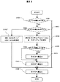
次に、図5と図3によって、本発明の光ディスク装置の動作の一実施例(モードI)を説明する。図5は、本発明の一実施例の動作手順を説明するためのフローチャートである。
以降の動作は、制御用マイクロコンピュータ19がカムコーダ内の必要な構成要素に、カムコーダの動作プログラムに従ってアクセスする(情報の吸上げとコントロールを行う)。なお、動作プログラムの判定若しくは算出、又は参照するために必要なデータは、あらかじめ、制御用マイクロコンピュータ19が取出せるように、例えば、制御用マイクロコンピュータ19に内蔵する図示しないメモリに保存されており、かつ、データの中身も必要に応じて更新されている。また、温度センサ4は、制御用マイクロコンピュータ19の処理動作に支障ない所定時間間隔で、レーザダイオード3の温度を検出して制御用マイクロコンピュータ19に出力している。また、フォトダイオード、その他の検出要素も同様である。
Next, an embodiment (mode I) of the operation of the optical disk apparatus of the present invention will be described with reference to FIGS. FIG. 5 is a flowchart for explaining the operation procedure of the embodiment of the present invention.
In the subsequent operations, the
図5において、ユーザがカムコーダ若しくは光ディスクの書込み(記録)若しくは読出し(再生)を、ボタン等のインターフェースを使って指示すると、ステップ501以降の動作が開始される。
まず、ステップ501では、温度センサ4の検出するレーザダイオード3の温度が規定温度以下か否かを判定する。レーザダイオード3の温度が規定温度以下であれば、ステップ502に進み、規定温度を超えていればステップ508に進む。
ステップ508では、レーザ光を出力し、ユーザがカムコーダ若しくは光ディスクの書込み(記録)若しくは読出し(再生)を行うことができる通常の動作に移行する。即ち、カムコーダは撮像した映像を光ディスク装置にセットされたDVD−RAM等のディスクへ書込み若しくは読出しを行い、書込み(記録)若しくは読出し(再生)後、動作を終了する。
ステップ502では、現在の温度から規定温度に達するまでの温度差を、上昇温度として算出する。
In FIG. 5, when the user instructs writing (recording) or reading (reproduction) of a camcorder or an optical disk using an interface such as a button, the operation after
First, in
In
In
ステップ503では、現在の温度でレーザ光が出力されない最大の電流値(即ち、検出された温度でのしきい値電流Ith)を、I−L特性データ(図1、図2、等参照。)を参照して取出し、そのしきい値電流Ith以下を供給電流とした時に必要な上昇温度の分レーザダイオード3の温度が上昇するのに要する時間を温度テーブル参照若しくは計算式により算出する。そして、供給する電流値をアナログフロントエンド20に出力する。なお、カムコーダには、あらかじめ出荷時に測定した温度特性データもテーブル若しくは計算式として、例えば、制御用マイクロコンピュータ19に内蔵されたメモリに、保存してある(後述の図7参照。)。
In
ステップ504では、アナログフロントエンド20が制御用マイクロコンピュータ19から指示された電流値をレーザダイオード3に供給する(プレヒート)。
ステップ505では、算出した時間が経過したか否かを判定し、経過していなければステップ506に進み、経過していれば電流供給を停止して、ステップ508に進む。
なお、ステップ508に移行して、ステップ508の動作を開始するまで、電流供給をそのまま維持しても良い。
なお、時間は算出せず、所定時間経過したら、再度温度センサの値から再計算して再度指示を出しても良い。
In
In
It should be noted that the current supply may be maintained as it is until the operation proceeds to step 508 and the operation of
The time may not be calculated, and when a predetermined time elapses, it may be recalculated again from the value of the temperature sensor and the instruction may be issued again.
ステップ506では、入射する光の強度のフォトダイオード25による検出結果をアナログフロントエンド20から受取り、光を検出した場合には“光感度有”としてステップ507に進み、検出しない場合にはステップ504に進む。
ステップ507では、アナログフロントエンド20が供給する電流値を所定値下げるように指示して電流値を下げて、ステップ504に進む。
以上述べたように、図5の実施例によれば、レーザ光を出力することのできない動作保証温度範囲外の低温であっても、レーザダイオードにしきい値以下の電流を流してレーザ光を出力しないで温度上昇させることにより、動作保証温度範囲内にしてから、レーザ光を出力を開始するので、正常な書込み若しくは読出しが実施できる。
In
In
As described above, according to the embodiment of FIG. 5, even if the temperature is outside the guaranteed operating temperature range where laser light cannot be output, a laser beam is output by passing a current below the threshold value through the laser diode. Without raising the temperature, the laser beam starts to be output after the temperature is within the guaranteed operating temperature range, so that normal writing or reading can be performed.
次に、図6と図3によって、本発明の光ディスク装置の動作の別の実施例(モードII)を説明する。図6は、本発明の一実施例であって、図5のモードIの動作をより簡便にした動作手順を説明するためのフローチャートである。
以降の動作でも図5と同様に、制御用マイクロコンピュータ19がカムコーダ内の必要な構成要素に、カムコーダの動作プログラムに従ってアクセスする(情報の吸上げとコントロールを行う)。なお、動作プログラムの判定若しくは算出、又は参照するために必要なデータは、あらかじめ、制御用マイクロコンピュータ19が取出せるように、例えば、制御用マイクロコンピュータ19に内蔵するメモリに保存されており、かつ、データの中身も必要に応じて更新されている。また、温度センサ4は、制御用マイクロコンピュータ19の処理動作に支障ない所定時間間隔で、レーザダイオード3の温度を検出して制御用マイクロコンピュータ19に出力している。また、フォトダイオード、その他の検出要素も同様である。
Next, another embodiment (mode II) of the operation of the optical disk apparatus of the present invention will be described with reference to FIGS. FIG. 6 is a flow chart for explaining an operation procedure which is an embodiment of the present invention and makes the operation of mode I of FIG. 5 simpler.
In the subsequent operations, as in FIG. 5, the
図6において、ユーザがカムコーダ若しくは光ディスクの書込み(記録)若しくは読出し(再生)を、ボタン等のインターフェースを使って指示すると、ステップ501以降の動作が開始される。
まず、ステップ501では、温度センサ4の検出するレーザダイオード3の温度が規定温度以下か否かを判定する。レーザダイオード3の温度が規定温度以下であれば、ステップ603に進み、規定温度を超えていればステップ508に進む。
ステップ508では、レーザ光を出力し、ユーザがカムコーダ若しくは光ディスクの書込み(記録)若しくは読出し(再生)を行うことができる通常の動作に移行する。即ち、カムコーダは撮像した映像を光ディスク装置にセットされたDVD−RAM等のディスクへ書込みを行い、書込み(記録)若しくは読出し(再生)後、動作を終了する。
In FIG. 6, when the user instructs writing (recording) or reading (reproduction) of a camcorder or an optical disk using an interface such as a button, the operation after
First, in
In
ステップ603では、図5のステップ502と同様に、現在の温度から規定温度に達するまでの温度差を、上昇温度として算出する。かつ、現在の温度でレーザ光が出力されない最大の電流値(即ち、検出された温度でのしきい値電流Ith)を、I−L特性データ(図1、図2、等参照。)を参照して取出し、そのしきい値電流Ith以下を供給電流とした時に必要な上昇温度の分レーザダイオード3が上昇するのに要する時間を温度テーブル参照若しくは計算式により算出する。そして、供給する電流値と時間(所定時間)とをアナログフロントエンド20に出力する。なお、カムコーダには、あらかじめ出荷時に測定した温度特性データもテーブル若しくは計算式として、例えば、制御用マイクロコンピュータ19に内蔵されたメモリに、保存してある(後述の図7参照。)。
In
ステップ604では、アナログフロントエンド20が制御用マイクロコンピュータ19から指示された電流値をレーザダイオード3に供給(プレヒート)し、指示された所定時間が経過した後、電流供給を停止して、ステップ508に進む。
なお、ステップ508に移行して、ステップ508の動作を開始するまで、電流供給をそのまま維持しても良い。
以上述べたように、レーザ光を出力することのできない動作保証温度範囲外の低温であっても、レーザダイオードにしきい値以下の電流を流してレーザ光を出力させないで温度上昇させることにより、動作保証温度範囲内にしてから、レーザ光を出力を開始するので、正常な書込み若しくは読出しが実施できる。
In
It should be noted that the current supply may be maintained as it is until the operation proceeds to step 508 and the operation of
As described above, even if the temperature is outside the guaranteed operating temperature range where laser light cannot be output, the current can be increased by passing the current below the threshold value through the laser diode without increasing the laser light. Since laser light output is started after the temperature is within the guaranteed temperature range, normal writing or reading can be performed.
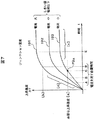
次に、図7を用いて、図5(モードI)若しくは図6(モードII)の処理動作において必要なテーブル若しくは計算式について説明する。図7は、レーザダイオードにしきい値電流以下の電流を供給した(供給電流をパラメータとした)時の、電流の供給時間を横軸としたレーザダイオードの上昇温度特性の一例を定性的に示す図である。曲線ID1は供給電流が大の時の経過時間−上昇温度曲線、曲線ID2は供給電流が中の時の経過時間−上昇温度曲線、曲線ID3は供給電流が小の時の経過時間−上昇温度曲線である。
しきい値電流を小、中、大としたときの経過時間tでのレーザダイオードの上昇温度△Tは、個々のレーザダイオードでばらつきがあり、異なる温度特性値となる。従って、例えば、カムコーダ又は光ディスク装置若しくはレーザダイオードの出荷時に個々のレーザダイオードの温度特性を取得して、取得した温度特性のデータをカムコーダ内のメモリ(例えば、制御用マイクロコンピュータ19に内蔵の図示しない不揮発性メモリ)に保存しておく。またはばらつきを含めた温度特性を予め実験的に求めておき上記メモリに保存しておいてもよい。
Next, a table or calculation formula necessary for the processing operation of FIG. 5 (mode I) or FIG. 6 (mode II) will be described with reference to FIG. FIG. 7 is a diagram qualitatively showing an example of the temperature rise characteristic of the laser diode with the current supply time as the horizontal axis when a current equal to or lower than the threshold current is supplied to the laser diode (with the supply current as a parameter). It is. Curve ID1 is an elapsed time-rise temperature curve when the supply current is large, curve ID2 is an elapsed time-rise temperature curve when the supply current is medium, and curve ID3 is an elapsed time-rise temperature curve when the supply current is small. It is.
The rising temperature ΔT of the laser diode at the elapsed time t when the threshold current is small, medium, and large varies among individual laser diodes and has different temperature characteristic values. Therefore, for example, the temperature characteristics of individual laser diodes are acquired at the time of shipment of the camcorder, the optical disk device, or the laser diode, and the acquired temperature characteristics data is stored in a memory in the camcorder (for example, not shown in the control microcomputer 19). Save to non-volatile memory. Alternatively, temperature characteristics including variations may be experimentally obtained in advance and stored in the memory.
図5のステップ503では、供給する電流(その温度でのしきい値電流以下)をI−L特性データから取出し、ステップ502で算出した上昇温度[a]に達するまでの時間を図7のグラフをもとにしたテーブル若しくは計算式から算出する。
例えば、図7のグラフにおいて、供給電流が小の場合には、曲線ID3と、必要な上昇温度[a]の線とが交差する点P3aを求め、点P3aでの経過時間tを参照することによって、上昇温度[a]と交差するところの時間Cを求めることができる。
図6のステップ603も、上述したステップ502とステップ503と同様に求める。
In
For example, in the graph of FIG. 7, when the supply current is small, the point P3a where the curve ID3 and the line of the necessary rise temperature [a] intersect is obtained, and the elapsed time t at the point P3a is referred to. Thus, the time C at which the rising temperature [a] intersects can be obtained.
Step 603 in FIG. 6 is also obtained in the same manner as
図7について、更に説明する。
レーザダイオードにしきい値Ith以下の電流を流すと、レーザ光は出力されないので、その電気エネルギの殆どは、レーザダイオードのジャンクションで熱エネルギに変換される。ジャンクションの熱容量をTc(単位:[J/℃])、与えられる熱量をQ(単位:[J])とした時、ジャンクションの上昇温度△T(単位:[℃])は、式(1)で求められる。
FIG. 7 will be further described.
When a current equal to or lower than the threshold value Ith is passed through the laser diode, no laser light is output, so most of the electric energy is converted into thermal energy at the junction of the laser diode. When the heat capacity of the junction is Tc (unit: [J / ° C.]) and the amount of heat applied is Q (unit: [J]), the junction rising temperature ΔT (unit: [° C.]) is expressed by the formula (1) Is required.
![]()
![]()
![]()
![]()
![]()
![]()
供給電流Idと供給電圧Vdを共に一定とすれば、電力Pも一定であるので、常時一定の熱量Qが与えられるので、上昇温度△Tは経過時間tに比例して上昇する(図7の[d])。実際には、熱がジャンクション外に逃げるので、Qo=α×(Tj−T0)の熱量が逃げる。ここで、αは熱伝導係数、Tjはジャンクション温度(単位:[℃])、T0は外部温度(単位:[℃])である。ジャンクション温度Tjが高くなればなるほど、逃げる熱量Q0が大きくなるので、図7の[c]のように飽和していく。しきい値電流が大きいほど、飽和するまでの時間が大きくなる(例えば、図7の上昇温度[b]での所要時間(経過時間)D)ので、しきい値電流が大きいほど、レーザダイオードをより大きく加熱可能である。 If both the supply current Id and the supply voltage Vd are constant, the power P is also constant, so that a constant amount of heat Q is always given, so that the rising temperature ΔT rises in proportion to the elapsed time t (FIG. 7). [D]). Actually, since heat escapes outside the junction, the amount of heat Qo = α × (Tj−T0) escapes. Here, α is a thermal conductivity coefficient, Tj is a junction temperature (unit: [° C.]), and T0 is an external temperature (unit: [° C.]). The higher the junction temperature Tj, the greater the amount of heat Q0 that escapes, so that saturation occurs as shown in [c] of FIG. The larger the threshold current, the longer the time until saturation (for example, the required time (elapsed time) D at the rising temperature [b] in FIG. 7). It can be heated more greatly.
従って、図5のモードIのフローチャートの動作手順を変更して、図8のモードIIIのように動作させれば、本発明のレーザダイオードの電流制御方法及び電流制御装置並びにカムコーダは、更に、良い結果を生むことができる。図8は、本発明の一実施例(モードIII)の動作手順を説明するためのフローチャートである。 Therefore, if the operation procedure of the flowchart of mode I in FIG. 5 is changed and the operation is performed as in mode III in FIG. 8, the laser diode current control method, current control apparatus, and camcorder of the present invention can be further improved. Can produce results. FIG. 8 is a flowchart for explaining the operation procedure of one embodiment (mode III) of the present invention.
以降の動作は、制御用マイクロコンピュータ19がカムコーダ内の必要な構成要素に、カムコーダの動作プログラムに従ってアクセスする(情報の吸上げとコントロールを行う)。なお、動作プログラムの判定若しくは算出、又は参照するために必要なデータは、あらかじめ、制御用マイクロコンピュータ19が取出せるように、例えば、制御用マイクロコンピュータ19に内蔵するメモリに保存されており、かつ、データの中身も必要に応じて更新されている。また、温度センサ4は、制御用マイクロコンピュータ19の処理動作に支障ない所定時間間隔で、レーザダイオード3の温度を検出して制御用マイクロコンピュータ19に出力している。また、フォトダイオード、その他の検出要素も同様である。
In the subsequent operations, the
即ち、図8において、ユーザがカムコーダ若しくは光ディスクの書込み(記録)若しくは読出し(再生)を、ボタン等のインターフェースを使って指示すると、ステップ501以降の動作が開始される。
そして、ステップ501では、温度センサ4の検出するレーザダイオード3の温度が規定温度以下か否かを判定する。レーザダイオード3の温度が規定温度以下であれば、ステップ803に進み、規定温度を超えていればステップ508に進む。
ステップ508では、レーザ光を出力し、ユーザがカムコーダ若しくは光ディスクの書込み(記録)若しくは読出し(再生)を行うことができる通常の動作に移行する。即ち、カムコーダは撮像した映像を光ディスク装置にセットされたDVD−RAM等のディスクへ書込みを行い、書込み(記録)若しくは読出し(再生)後、動作を終了する。
That is, in FIG. 8, when the user instructs writing (recording) or reading (reproduction) of a camcorder or an optical disk using an interface such as a button, the operation after
In
In
ステップ803では、現在の温度でのレーザ光が出力されない最大の電流値(即ち、検出された温度でのしきい値電流Ith)を、I−L特性データ(図1、図2、等参照。)を参照して取出し、そのしきい値電流Ithを供給電流とした時に必要な上昇温度までレーザダイオード3が上昇するのに要する時間を温度テーブル参照若しくは計算式により算出する。そして、供給する電流値と時間(所定時間)とをアナログフロントエンド20に出力する。なお、カムコーダには、あらかじめ出荷時に測定した温度特性データもテーブル若しくは計算式として、例えば、制御用マイクロコンピュータ19に内蔵されたメモリに保存してある。
In
ステップ804では、アナログフロントエンド20が制御用マイクロコンピュータ19から指示された電流値をレーザダイオード3に供給(プレヒート)し、ステップ506に進む。
ステップ506では、集光レンズ10を介してフォトダイオード25に入射する光の強度の検出結果をアナログフロントエンド20から受取り、光を検出した場合には“光感度有”としてステップ507に進み、検出しない場合にはステップ805に進む。
ステップ507では、アナログフロントエンド20が供給する電流値を所定値下げるように指示して電流値を下げて、ステップ804に戻る。
ステップ805では、プレヒートした時間が所定時間経過したか否かを監視し、経過していなければ監視を続け、経過した場合には、ステップ501に戻る。
ステップ501では、プレヒートされて温度が上昇したレーザダイオードの温度を再度判定し、規定温度を超えていればステップ508に進み、以下であれば、ステップ803以降に進み、現在の温度でのレーザ光が出力されない最大の電流値(即ち、検出された温度でのしきい値電流Ith)で、レーザダイオードに電流を供給する。
In
In
In
In
In
以上のように、図8のモードIIIの実施例では、所定周期(所定時間間隔)で温度を監視して、常に、レーザ光を出力しない最大の電流を供給するので、迅速かつ効率的にレーザダイオードを低温状態から動作保証温度まで到達させることができ、迅速かつ効率的に光ディスクへの書込み(記録)若しくは読出し(再生)が実施できる。
なお、所定周期は、温度範囲に応じて、時間間隔若しくは周期を変更しても良い。例えば、レーザダイオードの温度が低い範囲内では周期を長く設定し、温度が高い範囲内では、周期を短く設定する。また、温度が高い範囲内では、範囲設定を小さく取り、小刻みに周期設定を短くする等である。
以上述べたように、レーザダイオードは、レーザ光を出力することのできない動作保証温度範囲外の低温であっても、しきい値以下の電流を流して温度上昇させることにより、動作保証温度範囲内にしてから、レーザ光を出力を開始するので、正常な書込み若しくは読出し(再生)が実施できる。
As described above, in the embodiment of mode III in FIG. 8, the temperature is monitored at a predetermined cycle (predetermined time interval), and the maximum current that does not output the laser beam is always supplied. The diode can reach the guaranteed operating temperature from the low temperature state, and writing (recording) or reading (reproduction) to the optical disk can be performed quickly and efficiently.
In addition, the predetermined period may change a time interval or a period according to a temperature range. For example, the period is set to be long when the temperature of the laser diode is low, and the period is set to be short when the temperature is high. Further, within a high temperature range, the range setting is made small and the cycle setting is shortened in small increments.
As described above, even if the laser diode is at a low temperature outside the guaranteed operating temperature range where the laser beam cannot be output, the current within the guaranteed operating temperature range is increased by passing a current below the threshold. After that, since the output of the laser beam is started, normal writing or reading (reproduction) can be performed.
次に、本発明の他の実施例(モードIV)を図9によって説明する。図9は、簡便にレーザダイオードを動作保証温度範囲まで熱することができる動作手順である。
図9において、ユーザがカムコーダ若しくは光ディスクの書込み(記録)若しくは読出し(再生)を、ボタン等のインターフェースを使って指示すると、ステップ501以降の動作が開始される。
まず、ステップ501では、温度センサ4の検出するレーザダイオード3の温度が規定温度以下か否かを判定する。レーザダイオード3の温度が規定温度以下であれば、ステップ903に進み、規定温度を超えていればステップ508に進む。
ステップ508では、レーザ光を出力し、ユーザがカムコーダ若しくは光ディスクの書込み(記録)若しくは読出し(再生)を行うことができる通常の動作に移行する。即ち、カムコーダは撮像した映像を光ディスク装置にセットされたDVD−RAM等のディスクへ書込みを行い、書込み後(記録後)若しくは読出し(再生後)、動作を終了する。
Next, another embodiment (mode IV) of the present invention will be described with reference to FIG. FIG. 9 shows an operation procedure in which the laser diode can be easily heated to the operation guaranteed temperature range.
In FIG. 9, when the user instructs writing (recording) or reading (playback) of a camcorder or an optical disk using an interface such as a button, the operation after
First, in
In
ステップ903では、現在の温度でのレーザ光が出力されない最大の電流値(即ち、検出された温度でのしきい値電流Ith)を、I−L特性データ(図1、図2、等参照。)を参照して取出し、そのしきい値電流Ith以下を供給電流とした時に必要な上昇温度の分レーザダイオード3が上昇するのに要する時間を温度テーブル参照若しくは計算式により算出する。そして、供給する電流値について、図7の温度特性データから、飽和する時間(図7の時間E)を参照し、しきい値電流Ithと時間(所定時間)とをアナログフロントエンド20に出力する。なお、カムコーダには、あらかじめ出荷時に測定した温度特性データもテーブル若しくは計算式として、例えば、制御用マイクロコンピュータ19に内蔵されたメモリに、保存してある。
In
ステップ904では、アナログフロントエンド20が制御用マイクロコンピュータ19から指示された値の電流をレーザダイオード3に供給(プレヒート)し、ステップ508に進む。
なお、図9のモードIVの実施例では、温度上昇の途中で、レーザダイオードのしきい値Ithを超す電流が供給され、レーザ光が出力される場合があるので、レーザ光の照射位置を記録媒体の位置からはずしておくか又は記録媒体の記録領域(書込み領域若しくは読出し領域)とは無関係な場所(即ち、記録領域外)にピックアップを移動して照射位置を変えておく。また、更に焦点をぼかす(即ち、レーザ光の焦点位置を記録媒体の記録膜外に設定する)ようにしておく。そして、ステップ508では、一度供給電流をゼロにしてから、照射位置と焦点位置とを元の設定に戻して書込み若しくは読出しを開始する。
以上述べたように、レーザダイオードは、レーザ光を出力することのできない動作保証温度範囲外の低温であっても、しきい値以下の電流を流して温度上昇させることにより、動作保証温度範囲内にしてから、レーザ光を出力を開始するので、正常な書込み若しくは読出しが実施できる。
In
In the embodiment of mode IV in FIG. 9, since the current exceeding the threshold value Ith of the laser diode is supplied and the laser beam is output in the middle of the temperature rise, the irradiation position of the laser beam is recorded. The position is removed from the position of the medium, or the pickup position is moved to a place unrelated to the recording area (writing area or reading area) of the recording medium (that is, outside the recording area) to change the irradiation position. Further, the focal point is further blurred (that is, the focal position of the laser beam is set outside the recording film of the recording medium). In
As described above, even if the laser diode is at a low temperature outside the guaranteed operating temperature range where the laser beam cannot be output, the current within the guaranteed operating temperature range is increased by passing a current below the threshold. After that, since the output of the laser beam is started, normal writing or reading can be performed.
次に、本発明の他の実施例を図10によって説明する。図10は、カムコーダ若しくは光ディスク装置に低温スタンバイモードのオンオフ設定機能を備え、ユーザが、カムコーダ若しくは光ディスク装置について低温スタンバイモードに設定している場合には、上述の図5、図6、図8、若しくは図9の実施例(モードI〜モードIVのいずれか1つ)のフローチャートの手順を実行するようにしたものである。 Next, another embodiment of the present invention will be described with reference to FIG. FIG. 10 includes a low temperature standby mode on / off setting function in the camcorder or the optical disk apparatus, and when the user sets the low temperature standby mode for the camcorder or the optical disk apparatus, the above-described FIG. 5, FIG. 6, FIG. Alternatively, the procedure of the flowchart of the embodiment (any one of mode I to mode IV) of FIG. 9 is executed.
このモードを加えることにより、例えば、ユーザが、光ディスク装置のリムーバブル媒体を交換しようとする場合に、光ディスク装置の開閉蓋を開け閉めし、結露が発生し易い状態の時には、低温スタンバイモードをオフにすることで、レーザダイオードに結露を発生させないようにして、破損等による寿命が短くなることを防止することができる。
また、光ディスク装置の開閉蓋の開け閉めを行なった時には、自動的に所定時間低温スタンバイモードをオフにして、ファインダにその旨の警告を表示しても良い。
By adding this mode, for example, when the user tries to replace the removable medium of the optical disk device, the user opens and closes the open / close lid of the optical disk device, and turns off the low-temperature standby mode when condensation is likely to occur. By doing so, it is possible to prevent dew condensation from occurring in the laser diode and to prevent the lifetime from being shortened due to damage or the like.
Further, when the opening / closing lid of the optical disk apparatus is opened and closed, the low temperature standby mode may be automatically turned off for a predetermined time, and a warning to that effect may be displayed on the finder.
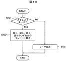
即ち、図10の実施例においては、ユーザがカムコーダ若しくは光ディスクの書込み(記録)若しくは読出し(再生)を、ボタン等のインターフェースを使って指示すると、ステップ1001以降の動作が開始される。
ステップ1001では、ユーザがカムコーダ若しくは光ディスク装置を低温スタンバイモードをオンに設定しているか否かを判定し、オンに設定されていることが判定によって分かれば、ステップ1002に進む。また、オフに設定していれば、図5等で説明したステップ508の書込み(記録)動作若しくは読出し(再生)動作を実行する。
ステップ1002では、図5、図6、図8、若しくは図9の既に説明したプレヒート動作を実行する。
以上述べたように、レーザダイオードは、レーザ光を出力することのできない動作保証温度範囲外の低温であっても、しきい値以下の電流を流して温度上昇させることにより、動作保証温度範囲内にしてから、レーザ光を出力を開始するので、正常な書込み若しくは読出しが実施できる。
That is, in the embodiment of FIG. 10, when the user instructs writing (recording) or reading (reproducing) of the camcorder or the optical disk using an interface such as a button, the operation after
In
In
As described above, even if the laser diode is at a low temperature outside the guaranteed operating temperature range where the laser beam cannot be output, the current within the guaranteed operating temperature range is increased by passing a current below the threshold. After that, since the output of the laser beam is started, normal writing or reading can be performed.
図11は、本発明の別の実施例で、図10の実施例の低温スタンバイモードのオンオフ設定機能に加え、ユーザが状況に応じて所望の低温スタンバイモードの種類を選択して設定できるものである。即ち、例えば、上述の図5、図6、図8、若しくは図9の実施例の動作モード(モードI〜IV)のいずれかを選択して実行するようにしたものである。
このモードを加えることにより、ユーザは、撮影の必要性や、環境条件、カムコーダ等の電子機器の状況に応じて、所望のモード若しくは低温スタンバイモードの種類を選択できるので、ユーザの使い勝手が向上する。
FIG. 11 shows another embodiment of the present invention. In addition to the low-temperature standby mode on / off setting function of the embodiment of FIG. 10, the user can select and set a desired low-temperature standby mode type according to the situation. is there. That is, for example, any one of the operation modes (modes I to IV) of the embodiment shown in FIG. 5, FIG. 6, FIG. 8, or FIG. 9 is selected and executed.
By adding this mode, the user can select the desired mode or the type of low-temperature standby mode according to the necessity of shooting, the environmental conditions, and the situation of the electronic device such as the camcorder, so that the user's convenience is improved. .
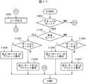
図11において、ステップ1001では、ユーザがカムコーダ若しくは光ディスク装置を低温スタンバイモードをオンに設定しているか否かを判定し、オンに設定されていることが判定によって分かれば、ステップ1101に進む。また、オフに設定していれば、図5等で説明したステップ508の書込み(記録)動作若しくは読出し(再生)動作を実行する。
ステップ508の動作の手順は、図10でも説明したが、図11では、図面の都合上、ステップ508を別に描き、T1とT2を用いて動作手順の接続をしている。
In FIG. 11, in
The operation procedure of
ステップ1101では、ユーザ設定が簡易モードで設定しているか否かを判定する。簡易モードの設定であればステップ1102に進み、そうでなければステップ1103に進む。
ステップ1102では、ユーザの設定した動作モードがモードII(図6参照)かモードIV(図9)か否かを判定し、モードIIならばステップ1104に進み、モードIVならばステップ1105に進む。
ステップ1103では、ユーザの設定した動作モードがモードI(図5参照)かモードIII(図8)か否かを判定し、モードIならばステップ1106に進み、モードIIIならばステップ1107に進む。
In
In
In
ステップ1104では、モードII(図6参照)の動作手順(ステップ501〜ステップ508)を実行する。
ステップ1105では、モードIV(図9参照)の動作手順(ステップ501〜ステップ508)を実行する。
ステップ1106では、モードI(図5参照)の動作手順(ステップ501〜ステップ508)を実行する。
ステップ1107では、モードIII(図8参照)の動作手順(ステップ501〜ステップ508)を実行する。
In
In
In step 1106, the operation procedure (step 501 to step 508) of mode I (see FIG. 5) is executed.
In
以上述べたように、レーザダイオードは、レーザ光を出力することのできない動作保証温度範囲外の低温であっても、しきい値以下の電流を流して必要な上昇温度の分温度上昇させることにより、動作保証温度範囲内にしてから、レーザ光の出力を開始するので、正常な書込み若しくは読出しが実施できる。 As described above, the laser diode can increase the temperature by the amount of the necessary rising temperature by flowing a current below the threshold even at a low temperature outside the guaranteed operating temperature range where laser light cannot be output. Since the output of laser light is started after the temperature is within the guaranteed operating temperature range, normal writing or reading can be performed.
次に、本発明の他の実施例を図12、図1、図2、及び図4を参照しながら説明する。図12は、レーザダイオードのI−L特性について、レーザダイオード毎に個々のばらつきがあることを説明するための図である。 Next, another embodiment of the present invention will be described with reference to FIG. 12, FIG. 1, FIG. 2, and FIG. FIG. 12 is a diagram for explaining that there are individual variations in the laser diode IL characteristics for each laser diode.
図12は、図1のレーザダイオードのI−L特性について、個々のレーザダイオード毎の特性に違いがあることを説明するための図である。図12に示すように、レーザダイオードLD1、LD2、及びLD3について、I−L特性が異なる。また、これらの特性は、経年変化でも変化してくる。
従って、工場での出荷調整時に、先ず個々のレーザダイオードについて、初期のI−L特性を、所定の温度毎に、所定のサンプリング数(所定の電流値毎)に測定してデータの採取を行い、そのデータをテーブル若しくは計算式として、カムコーダ、若しくは光ディスク装置に内蔵する若しくは接続できるメモリに保存している。なお、レーザパワーは、例えば、図3のブロック構成図に示すように、フォトダイオード等で光強度を測定して検出する。このように、データを保存することによって、本発明の一連の動作を実行できる。
FIG. 12 is a diagram for explaining that there is a difference in characteristics of each laser diode with respect to the IL characteristics of the laser diode of FIG. As shown in FIG. 12, the IL characteristics of the laser diodes LD1, LD2, and LD3 are different. In addition, these characteristics change over time.
Therefore, at the time of shipment adjustment at the factory, first, for each laser diode, the initial IL characteristic is measured at a predetermined temperature for each predetermined sampling number (for each predetermined current value), and data is collected. The data is stored as a table or a calculation formula in a camcorder or a memory that can be connected to or connected to the optical disc apparatus. The laser power is detected by measuring the light intensity with a photodiode or the like, for example, as shown in the block diagram of FIG. Thus, a series of operation | movement of this invention can be performed by preserve | saving data.
また更に、経年変化については、例えば、カムコーダ若しくは光ディスクの起動時に、温度センサの検出温度をもとに、設定最大パワーHIが出力される電流値Imaxとしきい値電流Ithを測定し、測定したデータにシフトするように保存してあったデータを置換することによって行う。なお、その時に、温度は設定の使用が無いが、例えば、本発明の実施例の如く、所定の温度範囲になるまでプレヒートすることで解決しても良い。 Further, with respect to aging, for example, when a camcorder or an optical disk is started, the current value Imax and threshold current Ith at which the set maximum power HI is output are measured based on the temperature detected by the temperature sensor. This is done by replacing the data stored so that it shifts to. At that time, the temperature is not used for setting, but may be solved by preheating until reaching a predetermined temperature range, for example, as in the embodiment of the present invention.
上述の実施例のレーザダイオード制御方法及び制御装置並びにカムコーダは、工場出荷前に、個々のレーザダイオードについて、初期の電流―レーザパワー特性を所定の温度をパラメータとして取得し、カムコーダ等のメモリに記憶し、かつ、温度毎のしきい値電流を記憶し、温度センサによってレーザダイオードの温度を監視し、低温時には、ユーザの指示に応じて、ユーザが低温スタンバイモードで使用することとしたときには、低温時には、温度に応じたしきい値以下の電流を供給する。供給中には、温度センサの検出温度を監視し、温度に応じたしきい値電流を供給するように制御するものである。
また好ましくは、温度上昇に追随してしきい値電流を増加させていくものである。
また経年変化に対しては、所定の最大出力パワーを出す電流値としきい値電流とが経年変化する。トレーニングモードを選択(若しくは、電源投入時)すると初期状態の特性からシフトした特性で制御するものである。
The laser diode control method, control apparatus, and camcorder of the above-described embodiment acquire the initial current-laser power characteristics for each laser diode as a parameter and store it in a memory such as a camcorder before shipment from the factory. In addition, the threshold current for each temperature is stored, the temperature of the laser diode is monitored by a temperature sensor, and when the user decides to use in the low temperature standby mode according to the user's instruction at low temperature, the temperature is low. In some cases, a current lower than a threshold corresponding to the temperature is supplied. During the supply, the temperature detected by the temperature sensor is monitored, and control is performed so as to supply a threshold current corresponding to the temperature.
Preferably, the threshold current is increased following the temperature rise.
Further, with respect to aging, the current value for producing a predetermined maximum output power and the threshold current change with aging. When the training mode is selected (or when the power is turned on), control is performed with characteristics shifted from the characteristics in the initial state.
即ち、上述の実施例のレーザダイオード制御方法は、レーザダイオードと、レーザ光を出力するための電流を供給してレーザダイオードを駆動する駆動装置と、レーザダイオードの近傍の温度を検出する温度センサとを備えたレーザダイオード制御装置のレーザダイオード制御方法であって、温度センサの温度が、レーザダイオードの所定値以下であった場合には、レーザダイオードのしきい値電流に対応する電流をレーザダイオードに供給し、所定時間経過後にレーザ光を出力する。 That is, the laser diode control method of the above-described embodiment includes a laser diode, a driving device that supplies a current for outputting laser light to drive the laser diode, and a temperature sensor that detects a temperature in the vicinity of the laser diode. A laser diode control method for a laser diode control device comprising: a laser diode that supplies a current corresponding to a threshold current of the laser diode when the temperature of the temperature sensor is equal to or lower than a predetermined value of the laser diode. The laser beam is output after a predetermined time has passed.
また上述の実施例のレーザダイオード制御装置は、レーザダイオードと、レーザ光を出力するための電流を供給してレーザダイオードを駆動する駆動装置とを備えたレーザダイオード制御装置において、レーザダイオードの近傍の温度を検出する温度センサと、レーザダイオードのしきい値電流を記録したメモリと、温度センサの検出する温度に基づいて、温度に対応するしきい値電流を駆動装置によってレーザダイオードに供給させ、温度センサの検出した温度がレーザダイオードの動作保証温度に達したことを確認してからレーザ光を出力する電流をレーザダイオードに供給させる制御手段を有する。
また好ましくは、上記レーザダイオード制御装置の制御手段は、温度センサの温度に応じて、所定周期でレーザダイオードに供給する電流を更新する。
The laser diode control device according to the above-described embodiment is a laser diode control device including a laser diode and a driving device that supplies a current for outputting laser light to drive the laser diode. Based on the temperature sensor for detecting the temperature, the memory in which the threshold current of the laser diode is recorded, and the temperature detected by the temperature sensor, the threshold current corresponding to the temperature is supplied to the laser diode by the driving device, and the temperature After confirming that the temperature detected by the sensor has reached the guaranteed operating temperature of the laser diode, there is provided control means for supplying the laser diode with a current for outputting the laser beam.
Preferably, the control means of the laser diode controller updates the current supplied to the laser diode at a predetermined cycle according to the temperature of the temperature sensor.
更に、上述の実施例のカムコーダは、レーザダイオードとレーザ光を出力するための電流を供給してレーザダイオードを駆動する駆動装置とを備えたレーザダイオード制御装置を有し、レーザダイオード制御装置によって記録媒体に取得した映像データを記録及び再生するカムコーダであって、レーザダイオードの近傍の温度を検出する温度センサと、レーザダイオードのしきい値電流を記録したメモリと、温度センサの検出する温度に基づいて、温度に対応するしきい値電流を駆動装置によってレーザダイオードに供給させ、温度センサの検出した温度がレーザダイオードの動作保証温度に達したことを確認してからレーザ光を出力する電流をレーザダイオードに供給させる制御手段とを有することを特徴とする。
また好ましくは、本発明のカムコーダの制御手段は、温度センサの温度に応じて、所定周期でレーザダイオードに供給する電流を更新する。
Furthermore, the camcorder of the above-described embodiment has a laser diode control device that includes a laser diode and a drive device that drives the laser diode by supplying a current for outputting laser light, and recording is performed by the laser diode control device. A camcorder that records and reproduces video data acquired on a medium, based on a temperature sensor that detects a temperature in the vicinity of the laser diode, a memory that records a threshold current of the laser diode, and a temperature detected by the temperature sensor Then, a threshold current corresponding to the temperature is supplied to the laser diode by the driving device, and after confirming that the temperature detected by the temperature sensor has reached the guaranteed operating temperature of the laser diode, the current that outputs the laser beam is And a control means for supplying to the diode.
Further preferably, the control means of the camcorder of the present invention updates the current supplied to the laser diode at a predetermined cycle according to the temperature of the temperature sensor.
上述のように、図1〜図12を参照して説明した実施例では、レーザ光を出力しない範囲でレーザダイオードに電流を流し、レーザダイオードの温度を動作保証温度に上昇させることができた。しかし、レーザダイオードの温度が動作保証温度に上昇したとしても、レーザ光が出力されるまでの立上がり時間は、低温であるほど長くなる傾向がある。
このため、レーザダイオードの温度が低い場合には、書込み若しくは読出しに必要なレーザパワーに達しないまま書込み若しくは読出しを行うことも考えられる。
例えば、書込み品質を確保するために、レーザダイオードの立上がり時間が、2[nS]以下である必要がある光ディスク装置があり、この光ディスク装置が搭載するレーザダイオードの動作保証温度は0[℃]〜40[℃]であって、レーザダイオードの温度が0[℃]の時の立上がり時間が3[nS]である場合を想定する。例えば0[℃]のときにその光ディスク装置で書込みをしようとすると、レーザダイオードの立ち上がり(発光の状態)が不十分な状態で光ディスクに書込みを行うことになる。その場合には、出力されるレーザ光のレーザパワーは書込みを行うのに十分なエネルギをもつレーザ光ではないので、ショボ書き等の記録品質の劣化発生する可能性が高い。なお、「ショボ書き」とは、2値データとして“0か”“1”かはっきりしない書込みの状態(書込み不良)を意味する。
このように、立上がり時間が長い程、書込み品質の劣化や読出しエラー(ミスリード)が発生する可能性が高い。
As described above, in the embodiment described with reference to FIGS. 1 to 12, it was possible to increase the temperature of the laser diode to the guaranteed operating temperature by supplying a current to the laser diode in a range where the laser beam is not output. However, even if the temperature of the laser diode rises to the operation guarantee temperature, the rise time until the laser beam is output tends to become longer as the temperature is lower.
For this reason, when the temperature of the laser diode is low, writing or reading may be performed without reaching the laser power necessary for writing or reading.
For example, there is an optical disk device in which the rise time of the laser diode needs to be 2 [nS] or less in order to ensure writing quality, and the guaranteed operating temperature of the laser diode mounted on this optical disk device is 0 [° C.] to Assume that the rise time is 40 [° C.] and the rise time is 3 [nS] when the temperature of the laser diode is 0 [° C.]. For example, if writing is to be performed with the optical disc apparatus at 0 [° C.], writing to the optical disc is performed in a state where the rise of the laser diode (light emission state) is insufficient. In that case, the laser power of the output laser beam is not a laser beam having sufficient energy for writing, so that there is a high possibility that the recording quality such as shobo writing will deteriorate. Note that “shobo writing” means a writing state (writing failure) in which “0” or “1” is not clear as binary data.
As described above, the longer the rise time, the higher the possibility of deterioration in write quality and a read error (misread).
そこで、本発明の別の実施例では、より短時間にレーザダイオードの温度を上昇させるため、しきい値電流超の電流をレーザダイオードに供給する。しきい値電流超の電流を供給するとレーザダイオードはレーザ光を出力する。しかしレーザダイオードの温度が動作保障温度範囲内であって、立上がり時間が光ディスク装置の書込み若しくは読出しに支障をきたす低温では、十分なエネルギをもつレーザ光ではないのでショボ書き等、記録品質が悪い結果となる可能性が高い。 Therefore, in another embodiment of the present invention, in order to raise the temperature of the laser diode in a shorter time, a current exceeding the threshold current is supplied to the laser diode. When a current exceeding the threshold current is supplied, the laser diode outputs a laser beam. However, at low temperatures where the laser diode temperature is within the guaranteed operating temperature range and the rise time hinders the writing or reading of the optical disk device, the laser beam is not sufficiently energetic. Is likely.
そこで、本発明の別の実施例では、レーザダイオードの温度が動作保障温度範囲内であって、立上がり時間が光ディスク装置の書込み若しくは読出しに支障をきたす温度のときには、レーザ光が出力されるほどの値の電流、即ちしきい値超の電流を供給して、急激にレーザダイオードの温度を上昇させる。そして、立上がり時間が光ディスク装置の書込み若しくは読出しに支障をきたさない温度まで迅速に上昇させてから、書込み(記録)動作若しくは読出し(再生)動作の実行を開始するものとする。 Therefore, in another embodiment of the present invention, when the temperature of the laser diode is within the guaranteed operating temperature range and the rise time is a temperature that hinders writing or reading of the optical disc apparatus, laser light is output. By supplying a current having a value, that is, a current exceeding a threshold value, the temperature of the laser diode is rapidly increased. Then, after the rise time is rapidly raised to a temperature that does not hinder the writing or reading of the optical disc apparatus, the execution of the writing (recording) operation or the reading (reproducing) operation is started.
このとき、書込み動作若しくは読出し動作を開始する前に出力されるレーザ光が照射されても光ディスクに影響が出ないように、レーザ光が照射される位置を光ディスクの記録領域(書込み領域若しくは読出し領域)の範囲外へ移動させてレーザ光を出力するものとする。
または、このとき、書込み動作若しくは読出し動作を開始する前に出力されるレーザ光が記録領域内の記録膜で焦点を結ばないように対物レンズの位置(光ディスク記録面からの距離)を制御するものとする。
上述のように、レーザ光が照射されても光ディスクに影響が出ないようにすることで、レーザ光が出力されるくらい大きな電流をレーザダイオードに供給し、レーザダイオードの立上がり時間が光ディスク装置の書込み若しくは読出しに支障をきたさない温度まで、レーザダイオードの温度を迅速に上昇させてから、書込み(記録)動作若しくは読出し(再生)動作の実行を開始することが可能となる。
At this time, the position irradiated with the laser beam is set to the recording area (write area or read area) of the optical disc so that the optical disc is not affected even if the laser beam outputted before starting the write operation or the read operation is irradiated. ) And output laser light.
Or, at this time, the position of the objective lens (distance from the optical disc recording surface) is controlled so that the laser beam outputted before starting the writing operation or reading operation is not focused on the recording film in the recording area. And
As described above, by preventing the optical disk from being affected by the laser light irradiation, a current large enough to output the laser light is supplied to the laser diode, and the rise time of the laser diode is written to the optical disk device. Alternatively, it is possible to start the execution of the writing (recording) operation or the reading (reproducing) operation after rapidly raising the temperature of the laser diode to a temperature that does not hinder reading.
図13、図14、及び図3によって、本発明の一実施例を説明する。図13及び図14は、図3の光学ヘッド1と光ディスク2及びスピンドルモータ22を模式的に示した図である。図13(a) 及び図14(a) は全体図である。また、図13(b) 及び図14(b) はピックアップ131の部分拡大図である。
現在、ブルーレイディスク(BD)ドライブ等の光ディスクドライブの構成においては、2レンズ方式が主流である。この方式は、互いに異なる焦点距離を有する2つの(一対の)対物レンズをピックアップ(光学ヘッド)に備え、例えばDVD用とBD用にそれぞれ切替えて用いるものである(例えば、特開平11−296880号公報、図4、図5参照。)。
An embodiment of the present invention will be described with reference to FIGS. 13, 14, and 3. FIG. 13 and 14 are diagrams schematically showing the
Currently, in the configuration of an optical disc drive such as a Blu-ray Disc (BD) drive, the two-lens method is the mainstream. In this system, two (a pair of) objective lenses having different focal lengths are provided in a pickup (optical head), and are switched between, for example, a DVD and a BD (for example, JP-A-11-296880). (See the publication, FIG. 4 and FIG. 5.)
図13及び図14において、131はピックアップ(光学ヘッド)、132は光ディスク、133はスピンドルモータ、134はピックアップ131の2つの対物レンズのうちの右レンズ、135はピックアップ131の2つの対物レンズのうちの左レンズ、斜線で示した領域136は光ディスク2の記録領域(書込み領域および読出し領域)、137は光ディスク2及びスピンドルモータ133の回転中心、138はシークモータの移動方向および移動範囲を示す矢印、132−1は光ディスク132の記録領域136の最内周記録線、132−2は光ディスク132の記録領域136の最外周記録線、140はトラッキングアクチュエータ(トラッキングACT)の移動方向である。
なお、図13では、記録領域136は、光ディスク132の裏面である。光ディスク132は、円盤状の記録媒体である。また、ピックアップ131は光ディスク132の下方からレーザ光を右レンズ134若しくは左レンズ135を通して記録領域136の所定の場所に照射する。
13 and 14, 131 is a pickup (optical head), 132 is an optical disk, 133 is a spindle motor, 134 is a right lens of two objective lenses of the
In FIG. 13, the
図13において、光ディスク132は、回転中心137を中心としてスピンドルモータ133の回転に従って回転する。ピックアップ131は、矢印138で示す方向(即ち、回転中心137を通る一点鎖線上をシークモータ(図3参照)によって左右方向)に沿って、点d1〜点d2間を移動する構成である。
ピックアップ131の右レンズ134及び左レンズ135は、ピックアップ131の移動方向138と平行で、シークモータによってピックアップ131が光ディスク132の半径方向を移動しても、常に回転中心137を通る一点鎖線上に位置するように配置されている。
図13では、ピックアップ131が、シークモータの動作により、一番内側(点d1)に位置し、左レンズ135は、最内周線132−1より内側に位置している。従って、この場合にはピックアップ131の左レンズ135を通過するレーザ光があっても、光ディスク132の記録領域136に照射されない。
In FIG. 13, the
The
In FIG. 13, the
次に、図14において、ピックアップ131が、シークモータの動作により、一番外側(点d2)に位置し、右レンズ134は、最外周線132−2より外側に位置している。従って、この場合にはピックアップ131の右レンズ134を通過するレーザ光があっても、光ディスク132の記録領域136に照射されない。
Next, in FIG. 14, the
上記、図14と図3によって説明した実施例について、図15を参照して更に説明する。図15は、本発明の一実施例の動作手順を説明するためのフローチャートである。
図15において、ユーザがカムコーダ若しくは光ディスクの書込み(記録)若しくは読出し(再生)を、ボタン等のインターフェースを使って指示すると、制御用マイクロコンピュータ19は、ステップ1501以降の動作を開始する。
ステップ1501では、温度センサ4の検出するレーザダイオード3の温度が規定温度以下か否かを判定する。レーザダイオード3の温度が規定温度以下であれば、ステップ1502に進み、規定温度を超えていればステップ508に進む。
ステップ508では、レーザ光を出力する通常の動作を行う。即ち、カムコーダは撮像した映像を光ディスク装置にセットされた光ディスクへ書込み若しくは読出し処理を行い、書込み(記録)後若しくは読出し(再生)後、動作を終了する。
The embodiment described with reference to FIGS. 14 and 3 will be further described with reference to FIG. FIG. 15 is a flowchart for explaining the operation procedure of the embodiment of the present invention.
In FIG. 15, when the user instructs writing (recording) or reading (reproduction) of the camcorder or the optical disk using an interface such as a button, the
In
In
ステップ1502では、DVD信号処理部16を介して伝達される制御用マイクロコンピュータ19からの指示により、モータアンプ21は、シークモータ24にシーク制御信号を出力し、シークモータ24を介してピックアップ131を光ディスク132の最外周記録線132−2より外側に右レンズ134が飛び出す位置に移動させる。
ステップ1503では、現在の温度に対するしきい値電流Ithを超える電流をレーザダイオード3に供給する。例えば、供給電流を、現在の温度のしきい値電流をI−L特性データ(図1、図2、等参照))から参照し、しきい値電流+5(即ち、Ith+5[mA])とする。そして、右レンズ134を介してレーザダイオード3を発光させる。即ち、アナログフロントエンド20は、制御用マイクロコンピュータ19から指示された電流値をレーザダイオード3に供給する(プレヒート)。
ステップ1504では、レーザダイオード3の温度が規定値(たとえば、動作保証温度の最低値+10[℃])を超えているか否かを判定する。温度が規定値を超えていなければステップ1503に戻り、プレヒートを続け、超えていれば電流供給を停止して、ステップ1505に進む。
In
In
In
ステップ1505では、モータアンプ21は、シーク制御信号をシークモータ24に出力し、シークモータ24を介して、ピックアップ131の右レンズ134の位置を所定の記録領域に移動させる。これにより、ピックアップ131は、レーザ光が光ディスク132(光ディスク2)に照射されると書込み若しくは読出しができる位置に移動し、ステップ508に進む。
なお、上記実施例では、レーザ光を出力するために供給する電流値を、しきい値電流+5[mA]としたが、しきい値電流以上であれば良く、最大の電流を供給しても良い。
In
In the above embodiment, the current value supplied to output the laser beam is set to the threshold current +5 [mA]. However, it may be equal to or greater than the threshold current, and the maximum current may be supplied. good.
図13〜図15では、レーザ光の照射位置を光ディスクの記録領域の範囲外へ移動させてレーザ光を出力する実施例を説明した。
なお、図15のステップ1502では一例として最外周にピックを移動させる例を示したが、これに限らず、最内周に移動させることとしてもよい。例えばピックの移動に要する時間を考慮すると、ステップ1502を行なう際のピック位置に応じて、最内周/最外周いずれか近い方に移動させ処理時間を短くすることができるからである。また、BD用、CD・DVD用の対物レンズの配置によっても制御は異なるため、適宜最内周/最外周を使い分けることとする。
次に、図16と図3を参照して、レーザ光を照射する場合に焦点位置をずらす実施例、即ち、書込み動作若しくは読出し動作を開始する前に、出力されるレーザ光が光ディスクの記録領域(書込み領域若しくは読出し領域)の記録膜上(記録膜の位置)で焦点を結ばないように光学ヘッド(ピックアップ)の対物レンズの位置(光ディスク記録面からの距離)を制御する実施例について説明する。
13 to 15, the embodiment in which the laser beam is output by moving the irradiation position of the laser beam out of the recording area of the optical disc has been described.
In addition, although the example which moves a pick to the outermost periphery was shown as an example in
Next, referring to FIG. 16 and FIG. 3, in the embodiment in which the focal position is shifted when irradiating the laser beam, that is, before starting the writing operation or the reading operation, the output laser beam is recorded in the recording area of the optical disc. An embodiment in which the position of the objective lens (distance from the optical disk recording surface) of the optical head (pickup) is controlled so as not to focus on the recording film (the position of the recording film) in the (writing area or reading area) will be described. .
図16は、光ディスクの記録膜とレーザ光の焦点位置を合わせない方法について説明するための図である。162は光ディスクの一部、163は光ディスク162の記録膜、164は対物レンズ、165、165−1、及び165−2は焦点位置である。また、矢印はレーザ光の進行方向を模式的に示すものである。
図16(a) は、光ディスク162の記録膜163に焦点位置165が合焦点している図、図16(b) は、光ディスク162の記録膜163より手前に焦点位置165−1がある図、図16(c) は、光ディスク162の記録膜163より後方に焦点位置165−2がある図を示す。
FIG. 16 is a diagram for explaining a method in which the recording film of the optical disc is not aligned with the focal position of the laser beam.
16A is a diagram in which the
フォーカスアクチュエータ(図3参照)を使って、図16(b) 若しくは図16(c) の如く、焦点位置を光ディスク162の記録膜163の位置からずらす設定にすることによって、光ディスク162の記録膜163には、レーザ光が照射されても、単位面積あたりのレーザパワーが弱く、書込み、若しくは読出しができないので、レーザ光を出力して迅速にレーザダイオードの温度を上昇させ、立上がり時間を早くすることができる。このため、レーザダイオードの温度が迅速に上昇した後、立上がり時間を気にせず、光ディスク162の記録膜163に、書込み若しくは読出しを開始することが可能となる。
By using a focus actuator (see FIG. 3), the
なお、フォーカスアクチュエータの代わりに、チルトアクチュエータ(不図示)を備えることにより、レーザ光の進行方向を斜め方向に変える(角度変更する)ことによって、焦点位置を光ディスクの書込み面及び読出し面からずらしても良い。また、フォーカスアクチュエータとチルトアクチュエータ両方を使って光ディスクの書込み面及び読出し面から焦点位置を変えても良い。 In addition, by providing a tilt actuator (not shown) instead of the focus actuator, the focal position is shifted from the writing surface and the reading surface of the optical disk by changing the traveling direction of the laser beam to an oblique direction (changing the angle). Also good. Further, the focus position may be changed from the writing surface and the reading surface of the optical disk by using both the focus actuator and the tilt actuator.
上記、図16と図3によって説明した実施例について、図17を参照して更に説明する。図17は、本発明の一実施例の動作手順を説明するためのフローチャートである。図17のフローチャートは、図15のフローチャートとほぼ同様で、同一の番号のステップの動作は、全く同じなので説明を省略する。ただし、ステップ1702及びステップ1705の前のステップ(ステップ1501、ステップ1504)からの移動、後のステップ(ステップ1703、ステップ508)への移動の順序についてはその限りではない。
The embodiment described with reference to FIGS. 16 and 3 will be further described with reference to FIG. FIG. 17 is a flowchart for explaining the operation procedure of the embodiment of the present invention. The flowchart in FIG. 17 is almost the same as the flowchart in FIG. 15, and the operations of the steps with the same number are exactly the same, and the description thereof will be omitted. However, the order of the movement from the previous step (
図17において、ステップ1702では、DVD信号処理部16を介して伝達される制御用マイクロコンピュータ19からの指示により、モータアンプ21は、フォーカスアクチュエータ8にフォーカス制御信号(図3参照)を出力し、フォーカスアクチュエータ8を介してレーザ光の焦点位置を光ディスクの記録膜163より前の位置165−1に変更し、ステップ1703に進む。
ステップ1703では、ステップ1503(図15参照)と同様にレーザダイオードに現在の温度に対するしきい値電流Ithを超える電流を供給する。
以降、ステップ1504でレーザダイオードの温度が所定の温度を超えた場合に、ステップ1705に進む。
In FIG. 17, in
In
Thereafter, when the temperature of the laser diode exceeds a predetermined temperature in
ステップ1705では、DVD信号処理部16を介して伝達される制御用マイクロコンピュータ19からの指示により、モータアンプ21は、フォーカスアクチュエータ8にフォーカス制御信号(図3参照)を出力し、フォーカスアクチュエータ8を介してレーザ光の焦点位置を正常位置、即ち、光ディスクの記録膜163の位置165に変更し、ステップ508に進む。なお、レーザが発光したまま焦点位置を正常位置(記録膜163の位置165)にすると光ディスクの記録膜163へ影響を与えるおそれがあるため、ステップ1705の前に一度レーザの発光を止めることとしてもよい。
以降、レーザ光を出力する通常の動作、即ち、カムコーダは撮像した映像を光ディスク装置にセットされた光ディスクへ書込み若しくは読出し処理を行い、書込み(記録)後若しくは読出し(再生)後、動作を終了する。
In
Thereafter, the normal operation of outputting laser light, that is, the camcorder writes or reads the captured image to or from the optical disc set in the optical disc apparatus, and terminates the operation after writing (recording) or reading (reproducing). .
図13〜図15の実施例では、レーザダイオードの温度が所定の温度以下であった場合には、ピックアップを最内周位置若しくは最外周位置に移動させる必要があった。この移動の完了するまでは、レーザダイオードに電流を供給できないため、無駄な時間があった。
また、図16及び図17の実施例では、焦点位置をフォーカスアクチュエータにより、記録膜163からずらし(即ち、焦点位置を記録媒体の記録膜外の位置に設定し)、更に元に戻す(即ち、焦点位置を記録媒体の記録膜の位置に設定する)時間が必要であるし、単位面積あたりのレーザパワーは低いが記録膜163にレーザ光が照射されているため記録膜163の劣化を招く恐れがある。
そこで、図13〜図15で説明した実施例と図16及び図17で説明した実施例を組合せた実施例について、図18によって説明する。図18は、本発明の一実施例の動作手順を説明するためのフローチャートである。
図18の実施例では、ピックアップの移動時間中には焦点位置を記録膜163に合わせない(即ち高さ方向に対して、焦点位置を記録媒体の記録膜外の位置に設定する)ようにしてレーザ光を出力し、ピックアップの移動が終了し、水平方向に対して最内周位置若しくは最外周位置に移動後(図18のステップ1502では一例として最外周位置に移動する場合を示す)、焦点位置を元に戻しておいて(即ち、焦点位置を記録媒体の記録膜の延長線上の位置に設定しておいて)レーザ光を出力する。即ちこの時、ピックアップは、水平方向に記録領域の外側に移動し、かつ、焦点位置を記録媒体の記録膜の位置に移動する。従って、ピックアップは、記録媒体の記録膜の延長線上の位置に設定される。
これによって、ピックアップの移動時間のロス、及び、記録膜163の劣化を最小限にすることができる。
In the embodiment shown in FIGS. 13 to 15, when the temperature of the laser diode is not more than a predetermined temperature, it is necessary to move the pickup to the innermost peripheral position or the outermost peripheral position. Until this movement is completed, no current can be supplied to the laser diode, so there is a wasted time.
16 and 17, the focal position is shifted from the
Accordingly, an embodiment in which the embodiment described in FIGS. 13 to 15 and the embodiment described in FIGS. 16 and 17 are combined will be described with reference to FIG. FIG. 18 is a flowchart for explaining the operation procedure of the embodiment of the present invention.
In the embodiment of FIG. 18, the focal position is not aligned with the
As a result, the loss of the moving time of the pickup and the deterioration of the
図18のフローチャートは、図15のフローチャートとほぼ同様で、同一の番号のステップの動作は、全く同じなので説明を省略する。ただし、各ステップ間の移動の順序についてはその限りではない。
図18において、ユーザがカムコーダ若しくは光ディスクの書込み(記録)若しくは読出し(再生)を、ボタン等のインターフェースを使って指示すると、制御用マイクロコンピュータ19は、ステップ1501以降の動作を開始する。
ステップ1501とステップ508の動作は、既に説明した通りである。ただし、ステップ1501で、レーザダイオード3の温度が規定温度以下であれば、ステップ1801に進む。
The flowchart in FIG. 18 is almost the same as the flowchart in FIG. 15, and the operations of the steps with the same number are exactly the same, and thus the description thereof is omitted. However, the order of movement between the steps is not limited thereto.
In FIG. 18, when the user instructs writing (recording) or reading (reproduction) of the camcorder or the optical disk using an interface such as a button, the
The operations in
ステップ1801では、使用するレーザダイオードの対物レンズの位置を確認し、対物レンズの位置が光ディスクの記録(書込み)領域若しくは再生(読出し)領域範囲内であるか否かを判定し、当該対物レンズの位置が光ディスクの記録領域(書込み領域若しくは読出し領域)内であればステップ1702に進み、領域範囲外であればステップ1500に進む。
ステップ1500では、図15のステップ1503を実行し、更にステップ1504でレーザダイオードの温度が規定温度超であれば、図18のステップ1505に進み、規定温度以下であれば、図15のステップ1503の処理を行う。
In
In
ステップ1702の処理で焦点位置を記録膜163からずらした(即ち、高さ方向に対して、焦点位置を記録媒体の記録膜外の位置に設定する)後、ステップ1703に進み、図17と同様にしきい値電流超の所定の電流をレーザダイオードに供給し、レーザ光が出力される状態でプレヒートする。
次のステップ1502では、プレヒートされた状態で対物レンズを最外周位置または最内周まで移動させる。図18のステップ1502では一例として最外周位置に移動する場合を示している。そして、ステップ1504でレーザダイオードの温度が規定値を超えていればステップ1705に進み、規定値以下であればステップ1503に進み図15と同様にプレヒートを続ける。
In
In the
ステップ1705では、図17と同様に、レーザ光の焦点位置を正常位置、即ち、光ディスクの記録膜163の延長線上の位置に変更する設定を行い、ステップ1505に進む。なお、レーザが発光したまま焦点位置を正常位置にすると光ディスクの記録膜163へ影響を与えるおそれがあるため、ステップ1705の前に一度レーザの発光を止めることとしてもよい。
ステップ1505では、図15と同様に、シークモータによりピックアップの対物レンズの位置を設定変更し所定の記録領域に移動させる。これにより、ピックアップは、レーザ光が照射されると書込み若しくは読出しができる位置に移動し、ステップ508に進む。
In
In
以上のように、図18の実施例に拠れば、レーザダイオードの温度が動作保証温度範囲内であっても、光ディスク装置の所定の書込み若しくは読出しに必要な時間より立上がり時間が長い場合に、迅速にレーザダイオードの温度を上昇させることにより、光ディスク装置の所定の書込み若しくは読出しに必要な時間以下の立上がり時間特性となる温度にすることができる。 As described above, according to the embodiment shown in FIG. 18, even when the temperature of the laser diode is within the operation guaranteed temperature range, if the rise time is longer than the time required for predetermined writing or reading of the optical disk device, By raising the temperature of the laser diode, it is possible to obtain a temperature having a rise time characteristic that is equal to or less than the time required for predetermined writing or reading of the optical disk device.
図18の実施例では、フォーカスアクチュエータによって、ピックアップの移動時間中には焦点位置を記録膜163に合わせないようにしてレーザ光を出力し、ピックアップの移動が終了し、水平方向に対して最内周位置若しくは最外周位置に移動後(図18のステップ1502では一例として最外周位置に移動する場合を示す)、フォーカスアクチュエータによって、焦点位置を元に戻しておいてレーザ光を出力した。このとき、シークモータによるピックアップの水平方向への移動は、厳密には、光ディスクの記録領域外であれば良いわけではなく、記録領域の境界より、更に所定の距離を移動させた方が望ましい。また、フォーカスアクチュエータによって、ピックアップを記録膜の位置に移動させてからレーザ光を出力した方が望ましい。
In the embodiment of FIG. 18, a laser beam is output by the focus actuator so that the focal position is not aligned with the
その理由を図24を用いて説明する。図24は、光ディスクの記録膜とレーザ光の焦点位置との関係を説明するための図である。
図24(a) は、ピックアップが、水平方向及び高さ方向にも、レーザ光を出力して良い適正な位置にあることを示す図である。また、図24(b) は、ピックアップが、水平方向には移動を完了している(適正な位置にある)が、高さ方向には移動が完了していないことを示す図である。162は光ディスクの一部、636は光ディスク162の記録膜、164は対物レンズ、665と665−1は焦点位置、661は記録領域内の水平方向の範囲を示す矢印、662は記録領域外の水平方向の範囲を示す矢印、663は記録膜の高さを示す線、666はレーザ光が記録膜636に照射された点である。図18において、記録膜の延長線上と記載した領域は、図24では、水平方向では、記録領域外662と高さ方向では、記録膜の高さを示す線663の部分である。なお、記録領域外の範囲は、図24では示していないが、光ディスクの記録膜636の外側と内側に存在する。また、矢印はレーザ光の進行方向を模式的に示すものである。
The reason will be described with reference to FIG. FIG. 24 is a diagram for explaining the relationship between the recording film of the optical disc and the focal position of the laser beam.
FIG. 24A is a diagram showing that the pickup is in an appropriate position where laser light can be output in both the horizontal direction and the height direction. FIG. 24 (b) is a diagram showing that the pickup has been moved in the horizontal direction (at an appropriate position) but has not been moved in the height direction.
図24(a) において、ピックアップの焦点位置665は、水平方向には記録領域外662にあり、高さ方向(焦点位置に対して)も記録膜636内にある。この状態の場合には、レーザ光は、矢印で示すように、記録膜636には照射されないため、記録膜636には影響がない。
しかし、図24(b) においては、ピックアップの焦点位置665−1は、水平方向には記録領域外662にある。しかし、高さ方向(焦点位置に対して)が記録膜636外にある。この状態の場合には、レーザ光が、図に矢印で示すように、記録膜636に照射されることがある(照射点666)。このため、記録膜636に損傷を与える恐れがある。従って、ピックアップの焦点位置が、記録膜の高さを示す線663に移動するまで、レーザダイオードの発光(出力)をしない方が良い。
また、ピックアップの高さ方向の位置が適正で(記録膜の高さを示す線上に)あっても、記録膜領域内661より、所定距離離れた位置でなければならないことも理解できたであろう。従って、本発明では、最内周記録線及び最外周記録線とは、焦点距離と対物レンズから出るレーザ光の角度から所定距離内側若しくは外側に離れた距離をオフセットとして考慮した位置である。
In FIG. 24A, the
However, in FIG. 24B, the focal position 665-1 of the pickup is outside the recording area 662 in the horizontal direction. However, the height direction (with respect to the focal position) is outside the
It was also understood that even if the position in the height direction of the pickup is appropriate (on the line indicating the height of the recording film), it must be located at a predetermined distance from the
次に、図13〜図15で説明した実施例と図16及び図17で説明した実施例を組合せた別の実施例について、図19によって説明する。図19は、本発明の一実施例の動作手順を説明するためのフローチャートである。
図19の実施例では、ピックアップが記録領域内を移動中には、レーザダイオードにしきい値電流以下の電流を供給して、レーザ光を出力しない程度で加熱し、ピックアップの移動が終了し、最内周位置若しくは最外周位置の記録領域外に移動後、レーザ光を出力する。これによって、ピックアップの移動時間のロス、及び、焦点距離の変更若しくは切替え時間のロスを無くす。
Next, another embodiment in which the embodiment described in FIGS. 13 to 15 and the embodiment described in FIGS. 16 and 17 are combined will be described with reference to FIG. FIG. 19 is a flowchart for explaining the operation procedure of the embodiment of the present invention.
In the embodiment of FIG. 19, while the pickup is moving in the recording area, a current below the threshold current is supplied to the laser diode and heated to such an extent that no laser beam is output. After moving outside the recording area at the inner peripheral position or the outermost peripheral position, the laser beam is output. This eliminates the loss of pickup movement time and the loss of focal length change or switching time.
図19のフローチャートは、図18のフローチャートとほぼ同様で、同一の番号のステップの動作は、全く同じなので説明を省略する。ただし、各ステップ間の移動の順序についてはその限りではない。
図19において、図18と異なるステップは、ステップ1702とステップ1703の代わりに、図9で説明したステップ903とステップ904を入れた処理手順としたことである。
ステップ1801では、使用するレーザダイオードの対物レンズの位置、即ちピックアップが記録領域範囲内であるか否かを判定し、記録領域内であれば図9のステップ903に進み、領域範囲外であればステップ1500に進む。
The flowchart of FIG. 19 is substantially the same as the flowchart of FIG. However, the order of movement between the steps is not limited thereto.
In FIG. 19, a step different from FIG. 18 is that a processing
In
なお、ステップ903とステップ904の処理は、図9で説明した通りなので説明を省略する。
ただし、ステップ904では、プレヒートを続けながらステップ1502に進み、ピックアップが記録領域外に移動するまで、しきい値電流以下の電流を流し続けレーザダイオードを暖める。
なお、しきい値電流は、レーザダイオードの温度で変わるので、図9では、温度上昇につれてステップ501で温度を測定し、しきい値電流を変更していた。しかし、図19の実施例では、ピックアップが記録領域外へ移動するまでの時間なので、その動作をしていない。
Note that the processing in
However, in
Since the threshold current changes depending on the temperature of the laser diode, in FIG. 9, the temperature is measured in
なお、上記図13、図14の実施例においては、光ピックアップに設けた2つの対物レンズの配置が、光ディスクの半径方向(ピックアップの移動方向)に沿って配置している。しかし、例えば、対物レンズの配置が、光ディスクの半径方向(ピックアップの移動方向)に直交するように配置する、等、対物レンズの配置は、光ディスクの記録再生領域外に移動できるような構成であれば、どのようなものであっても良いことは自明である。
また、ピックアップに設ける対物レンズの数も2つである必要は無く、用途によって、1つであっても、複数あっても良いことは勿論のことである。
In the embodiments of FIGS. 13 and 14, the two objective lenses provided in the optical pickup are arranged along the radial direction of the optical disk (the movement direction of the pickup). However, the arrangement of the objective lens can be moved out of the recording / reproducing area of the optical disc, for example, the arrangement of the objective lens is orthogonal to the radial direction of the optical disc (the moving direction of the pickup). It is obvious that anything can be used.
Further, the number of objective lenses provided in the pickup need not be two, and it is needless to say that one or more objective lenses may be provided depending on the application.
以上述べた図1〜図12の実施例と、図13〜図19の実施例を組み合わせると次の図20のフローチャートに示すような使い方ができる。
即ち、図20において、光ディスク装置若しくは光ディスク装置搭載したカムコーダ等の機器において、レーザダイオードの動作保証温度範囲外の低温でユーザが使用しようとした場合には、まず図1〜図12の実施例を適用する。
ステップ2001では、図5、図6、図8、若しくは図9のフローチャートのステップ501の処理を行う。即ち、レーザダイオードが動作保証温度以下か否かを判定し、動作保証温度以下である場合には、ステップ2002に進み、動作保証温度以下ではないならば、ステップ2003に進む。
ステップ2002では、図5、図6、図8、若しくは図9の処理のステップ501以降、ステップ508に至る前のステップの処理まで実行し、ステップ2003に進む。
このように、しきい値電流以下の電流をレーザダイオードに供給して、レーザ光を出力させない状態でレーザダイオードを暖め、動作保証温度範囲内までレーザダイオードの温度を上昇させる。
When the embodiment shown in FIGS. 1 to 12 described above and the embodiment shown in FIGS. 13 to 19 are combined, it can be used as shown in the flowchart of FIG.
That is, in FIG. 20, in a device such as an optical disk device or a camcorder mounted with the optical disk device, when the user tries to use at a low temperature outside the guaranteed operating temperature range of the laser diode, first, the embodiment of FIGS. Apply.
In
In
In this manner, a current equal to or lower than the threshold current is supplied to the laser diode, and the laser diode is warmed in a state where laser light is not output, and the temperature of the laser diode is increased to within the guaranteed operating temperature range.
次に、図13〜図19の実施例を適用する。
即ち、図20において、ステップ2003では、図15、図17、図18若しくは図19のステップ1501の処理を行う。つまり、レーザダイオードが規定の温度以下か否かを判定し、規定温度以下である場合には、ステップ2004に進み、規定温度以下ではないならば、ステップ508に進む。
ステップ2004では、図15、図17、図18若しくは図19の処理のステップ1501以降、ステップ508に至る前のステップの処理まで実行し、ステップ508に進む。
Next, the embodiments of FIGS. 13 to 19 are applied.
That is, in FIG. 20, in
In
ステップ508では、レーザ光を出力する通常の動作を行う。即ち、カムコーダは撮像した映像を光ディスク装置にセットされた光ディスクへ書込み若しくは読出し処理を行い、書込み(記録)後若しくは読出し(再生)後、動作を終了する。
以上のように、レーザ光を出力することが可能なしきい値電流超の電流をレーザダイオードに供給して、書込み領域に、書込み若しくは読出しができない状態でレーザ光を出力する。これによって、更にレーザダイオードの温度を上昇させ、立上がり時間が光ディスク装置若しくは光ディスク装置搭載したカムコーダ等の機器の書込み若しくは読出し品質が保持できる温度に上昇してから、光ディスクへの書き込み若しくは読出しを行う。
In
As described above, a current exceeding a threshold current capable of outputting laser light is supplied to the laser diode, and the laser light is output to the writing area in a state where writing or reading cannot be performed. As a result, the temperature of the laser diode is further raised, and the rise time rises to a temperature at which the writing or reading quality of equipment such as an optical disk device or a camcorder equipped with the optical disk device can be maintained, and then writing or reading to the optical disk is performed.
なお、図19の実施例では、ステップ1501でレーザダイオードの温度を検出し、規定温度以下であるならば記憶領域内か否かを判定して処理を実行した。また、図13以降の実施例は、規定温度がレーザダイオードの動作保証温度内であることが条件になっている。そして、ピックアップの位置が記録領域内にある時の動作が主体となっている。
しかし、図19の実施例を変えて、図19のステップ1501では、規定温度を動作保証温度とし、ピックアップが記録領域内に位置していた場合に、ピックアップが記録領域外に移動するまで、レーザ光を出力しないでプレヒートし、その後、レーザダイオードの温度が動作保証温度を超えた場合には、立上がり時間が書込み若しくは読出しが可能な条件下の温度になるまで加熱を続け、その後記録領域内の所定の位置にピックアップを移動して書込み若しくは読出しを開始するようにしても良い。
In the embodiment of FIG. 19, the temperature of the laser diode is detected in
However, instead of the embodiment of FIG. 19, in
上記図1〜図20の実施例では、レーザダイオードを所定の温度に上昇させた後、光ディスクに書込み(記録)を実行していた。しかし、場合によっては、すぐに記録しなければ撮影チャンス若しくは記録チャンスを逃すことも考えられる。そこで、以下の実施例の如く、カムコーダ等の情報記録再生装置に用いられる光ディスク装置において、撮影チャンス若しくは記録チャンスを逃すことなく、光ディスクへの記録を実行することができる。 1 to 20, the laser diode is raised to a predetermined temperature and then written (recorded) on the optical disk. However, depending on the case, if the recording is not performed immediately, it is possible to miss a shooting opportunity or a recording opportunity. Therefore, as in the following embodiment, in an optical disk device used in an information recording / reproducing apparatus such as a camcorder, recording on an optical disk can be executed without missing a shooting opportunity or a recording opportunity.
図21は、本発明のカムコーダの一実施例の構成を示すブロック図である。図21は、図3の実施例のカムコーダと同一の構成要素には、同一の参照番号を付し、説明を省略する。その他、26はハードディスク装置、27はRAM、である。
図21において、ハードディスク装置26は、制御用マイクロコンピュータ19とATAPI( AT Attachment Packet Interface )で接続されている。また、RAM27は、図3のプレイバックRAM17とレコーディングRAM18を含む。
FIG. 21 is a block diagram showing the configuration of an embodiment of the camcorder of the present invention. In FIG. 21, the same components as those of the camcorder of the embodiment of FIG. In addition, 26 is a hard disk device, and 27 is a RAM.
In FIG. 21, the
図21の処理について、図22のフローチャートを使って説明する。図22は、本発明の一実施例の動作手順を説明するためのフローチャートである。
なお以降の動作は、制御用マイクロコンピュータ19がカムコーダ内の必要な構成要素に、カムコーダの動作プログラムに従ってアクセスする(情報の吸上げとコントロールを行う)。
図22において、ユーザがカムコーダ若しくは光ディスクの書込み(記録)若しくは読出し(再生)を、ボタン等のインターフェースを使って指示すると、ステップ2101以降の動作が開始される。
The processing of FIG. 21 will be described using the flowchart of FIG. FIG. 22 is a flowchart for explaining the operation procedure of the embodiment of the present invention.
In the subsequent operations, the
In FIG. 22, when the user instructs writing (recording) or reading (reproduction) of a camcorder or an optical disk using an interface such as a button, the operation after
ステップ2101では、レーザダイオードの温度を検出し、すぐに光ディスクに書込みが可能か否かを判定する。もし書込み可能ならばステップ2106に進む。また書込みができない場合には、ステップ2102に進む。
ステップ2102では、レーザダイオードの温度状態から、上述の図1乃至図12のいずれかの実施例を適用するか、図13乃至図18のいずれかの実施例を適用するか、若しくは図19乃至図20のいずれかの実施例を適用するかを判定して、いずれかの処理動作の実行を開始する(本実施例では、図20のステップ2001〜2004を実行する)。それと同時に、HDDのスピンアップを開始しHDDを書込み可能な状態に移行させる。その後、ステップ2103に進む。
ステップ2103では、HDDへの書込みが可能か否か(例えば、スピンアップが終了したか否か)を判定する。もし書込み可能ならばステップ2105に進む。また書込みができない場合には、ステップ2104に進む。
In
In
In
ステップ2104では、RAM27に取得したデータを保存して、ステップ2105に進む。このとき、ステップ2105には予め定められた所定時間後若しくは、RAM27の記録容量が一杯になる前に移行する。
ステップ2105では、HDD26にRAM27で取得したデータとその後に続いて入力されたデータを保存して、ステップ2106に進む。
ステップ2106では、光ディスク2にHDD26が保存したデータの書込みを開始する。HDD26から、すべてのデータを光ディスクに書込んでしまったら、光ディスクには、直接RAM27から出力されるデータを書き込む。
以降ユーザからの指示があるまで、処理を実行する。
In
In
In
Thereafter, the process is executed until an instruction from the user is given.
なお、RAM27は、HDD26が書込み開始可能になるまでデータを記録し続けられる程度の十分な記録容量を有する。また、同様に、HDD26の記録容量は近年大容量化が進んでいるので問題はないと思うが、光ディスク2に書込みが可能になるまでの十分な容量があるものを使用する。
以上述べたように、図21及び図22の実施例によれば、レーザダイオードが低温下で光ディスクが書込み不能若しくは書込み品質が悪いときであっても、ユーザの指示通りに、迅速に光ディスクに書込みができる。これによって、ユーザが記録したいデータを失わずに済む。
なお、図20及び図21の実施例では、RAMとHDDを使用したが、他の形式の記録媒体でも良いことは勿論である。例えば、RAM以外の半導体メモリでも良い。
The
As described above, according to the embodiments of FIGS. 21 and 22, even when the laser diode is at a low temperature and the optical disk cannot be written or the writing quality is poor, the optical disk can be quickly written according to the user's instruction. Can do. This eliminates the loss of data that the user wants to record.
20 and 21, the RAM and HDD are used, but it is needless to say that other types of recording media may be used. For example, a semiconductor memory other than RAM may be used.
図21のカムコーダの処理の別の実施例を図23によって説明する。図23は、本発明の一実施例の動作手順を説明するための図である。図23の実施例は、ステップ2301とステップ2302を追加し、ステップ2102の代わりにステップ2102′を採用したものである。即ち、図23は、図22の実施例のステップ2101の「NO」の分岐とステップ2102′の間に、ステップ2301を挿入し、ステップ2301の「NO」の分岐とステップ2102′を接続し、ステップ2301の「YES」の分岐にステップ2302を追加し、ステップ2302の処理をステップ2106に接続したフローチャートである。従って、図22で説明したステップについては説明を省略する。ただし、各ステップ間の移動の順序についてはその限りではない。
Another embodiment of the processing of the camcorder of FIG. 21 will be described with reference to FIG. FIG. 23 is a diagram for explaining the operation procedure of the embodiment of the present invention. In the embodiment of FIG. 23,
図23において、ステップ2101で、レーザダイオードの温度を検出し、すぐに光ディスクに書込みができない場合には、ステップ2301に進む。
ステップ2301では、DVDへの書込みが可能になる時間(プレヒートが完了するまでの時間)とHDDへの書込みが可能になる時間(スピンアップが完了するまでの時間)とを比較する。そして、HDDへの書込みが可能になる時間の方が、DVDへの書込みが可能になる時間より短ければ、ステップ2102′に進む。また、DVDへの書込みが可能になる時間の方が、HDDへの書込みが可能になる時間より短かければ、ステップ2302に進む。
ステップ2301では、レーザダイオードの温度状態から、予め決められた処理、例えば、図15の実施例によりDVDへの書込みが開始可能になるまでの時間を算出する。算出した時間とHDDへの書込みが開始可能になる時間とを比較する。そして、HDDへの書込み開始可能な時間が短ければステップ2102′に進み、DVDへの書込み開始可能な時間が短ければステップ2302に進む。
ステップ2102′では、光学ヘッド1に対して図15のステップ1502〜ステップ1505の処理を行い、かつ、HDD26に対してスピンアップを開始して、ステップ2103に進む。
ステップ2302では、光学ヘッド1に対して図15のステップ1502〜ステップ1505の処理を行い、ステップ2106に進む。
In FIG. 23, if the temperature of the laser diode is detected in
In
In
In
In Step 2302, the processing from
なお、ステップ2301での光学ヘッド1の書込み可能時間の算出やHDDへの書込み開始可能な時間、等は、あらかじめ、制御用マイクロコンピュータ19が取出せるように、例えば、制御用マイクロコンピュータ19に内蔵する図示しないメモリに保存されており、かつ、データの中身も必要に応じて更新されている。また、書込み可能時間の算出ではなく、予めメモリに保存されたテーブル等のデータ表を参照しても良い。
また、図23の実施例においては、図15の実施例によってDVDの書込み時間を制御したが、制御方法についてはこれに限らないことは自明である。
また、ステップ2301において、本発明のいずれかの実施例を適用すると一番短時間に書込みが可能かを算出及び判定し、一番短時間に書込み可能な処理を選択して適用するようにしても良い。
The calculation of the writeable time of the
In the embodiment of FIG. 23, the DVD writing time is controlled by the embodiment of FIG. 15, but it is obvious that the control method is not limited to this.
In
図23の実施例によれば、(1)レーザダイオードのプレヒートが完了するまでの時間と(2)HDDのスピンアップのが完了するまでの時間とを比較し、(1)が短いか(1)と(2)が同じ場合には、HDDのスピンアップを開始せずにレーザダイオードのプレヒートを実施し、(2)が短い場合には、プレヒートとスピンアップを同時に開始し、HDDへ記録しつつレーザダイオードのプレヒートが完了したならば光ディスクへの記録へバトンタッチすることが可能となる。このように、記録が可能になるまでの処理時間を考慮して記録先を変更することにより、ユーザデータを迅速に記録することが可能となる。また、処理時間を考慮してHDDをスピンアップさせないようにも制御するため、HDDのスピンアップの回数を節約し、消費電力を節約でき、特にバッテリ等を使用する携帯用の電子機器には有効である。 According to the embodiment of FIG. 23, (1) the time until the preheating of the laser diode is completed and (2) the time until the HDD spin-up is completed are compared. ) And (2) are the same, the laser diode is preheated without starting HDD spin-up, and when (2) is short, preheat and spinup are started simultaneously and recorded on the HDD. On the other hand, if the preheating of the laser diode is completed, it is possible to touch the recording on the optical disk. In this way, user data can be quickly recorded by changing the recording destination in consideration of the processing time until recording is possible. In addition, since the HDD is not controlled to be spun up in consideration of the processing time, the number of times the HDD is spun up can be saved, power consumption can be saved, and it is particularly effective for portable electronic devices that use batteries. It is.
上述の実施例においては、光ディスク装置と一体化したカムコーダを例にして説明した。しかし、本発明は、それに限らず、一体化していないビデオカメラ(デジタルカメラを含む)でも、光ディスク装置だけの場合でも適用可能であり、またカムコーダ等のカメラに限らず、光ディスク装置を情報記録装置若しくは情報再生装置又は情報記録再生装置として搭載する電子機器、特に携帯用の電子機器に適用できる。
例えば、PDA( Personal Digital Assistant )、携帯電話機器、等でも良い。
In the above-described embodiments, the camcorder integrated with the optical disc apparatus has been described as an example. However, the present invention is not limited to this, and can be applied to a video camera (including a digital camera) that is not integrated or an optical disk apparatus alone, and is not limited to a camera such as a camcorder, and the optical disk apparatus is an information recording apparatus. Alternatively, the present invention can be applied to an electronic device mounted as an information reproducing device or an information recording / reproducing device, particularly a portable electronic device.
For example, a PDA (Personal Digital Assistant), a mobile phone device, or the like may be used.
なお、本発明は、光ディスク装置を記録媒体の書込み若しくは読出しに使用するレーザダイオードに関する。しかし、特に、書込み(記録)と読出し(再生)の両方について、レーザ等の光を使用するCD、DVD、次世代DVD、等である必要は無い。即ち書込み若しくは読出しの少なくとも一方に本発明を適用すれば良い。例えば、書込みだけに本発明を適用するようにすれば、読出しに磁気を使用する光磁気記録方式の記録媒体、例えば、MO( Magneto-Optical Disc )やMD( Mini Disc )でも良い。また、MDの例を挙げた如く、記録する目的や対象が何であっても良い。
また、カムコーダに使用する光ディスク装置に限らず、光ディスク装置を用いた情報記録再生装置やレコーダ単体での書込みにも適用できることは勿論である。
また、上記実施例で使用した記録媒体は、円盤状の光ディスクであった。しかし、あくまで実施例であって、本発明に適用する光ディスクの形状は、円盤状に限られるものではないことは勿論である。
The present invention relates to a laser diode that uses an optical disk device for writing or reading a recording medium. However, it is not particularly necessary to use a CD, DVD, next-generation DVD, or the like that uses light such as a laser for both writing (recording) and reading (reproduction). That is, the present invention may be applied to at least one of writing and reading. For example, if the present invention is applied only to writing, a magneto-optical recording system recording medium using magnetism for reading, for example, MO (Magno-Optical Disc) or MD (Mini Disc) may be used. Further, as described in the MD example, the purpose and target of recording may be anything.
Of course, the present invention can be applied not only to an optical disk device used for a camcorder but also to an information recording / reproducing apparatus using an optical disk device or writing by a recorder alone.
The recording medium used in the above example was a disk-shaped optical disk. However, it is only an example, and it is needless to say that the shape of the optical disk applied to the present invention is not limited to a disk shape.
更に本発明は、レーザダイオードだけに限らず、同様の特性を持つLED( Light Emitting Device )等にも適用でき、信号灯、屋外照明機器、電光掲示板等の広告表示装置、交通標識、テレビ放送受像機等にも有効に適用可能である。
更に、上述の温度センサは温度を直接検出するが、熱伝対のように別の物理的単位のデータを検出して、制御用マイクロコンピュータ等の制御部で温度に換算しても良いし、テーブル若しくは計算式を温度ではなく、温度センサの検出する物理的単位のデータで表しても良い。
Furthermore, the present invention can be applied not only to laser diodes but also to LEDs (Light Emitting Devices) having similar characteristics, such as signal lights, outdoor lighting equipment, advertising display devices such as electric bulletin boards, traffic signs, and television broadcast receivers. It can be effectively applied to the above.
Furthermore, although the temperature sensor described above directly detects the temperature, it may detect data of another physical unit such as a thermocouple and convert it to a temperature by a control unit such as a control microcomputer. The table or the calculation formula may be represented not by temperature but by data of a physical unit detected by the temperature sensor.
以上のように、上述の実施例によれば、レーザダイオードは、レーザ光を出力することのできない動作保証温度範囲外の低温であっても、しきい値以下の電流を流して温度上昇させることにより、動作保証温度範囲内にしてから、レーザ光の出力を開始するので、動作保証温度以下の低温でも正常な書込みが実施できる。
以上、本発明によれば、例えばカムコーダ等の情報記録再生装置を屋外で使用する場合など、低温キンク現象が発生するほど低温な使用環境であっても、情報の適切な記録・再生を行うことができるレーザダイオードの制御方法及び制御装置並びに情報記録再生装置を提供することができる。
以上、本発明を各実施例によって説明したが、当業者には、本発明の精神を逸脱しない範囲で種々の変形が可能であることはいうまでもない。
As described above, according to the above-described embodiment, the laser diode raises the temperature by flowing a current below the threshold value even at a low temperature outside the guaranteed operating temperature range where laser light cannot be output. Thus, since the output of the laser beam is started after the temperature is within the guaranteed operating temperature range, normal writing can be performed even at a low temperature below the guaranteed operating temperature.
As described above, according to the present invention, information can be appropriately recorded and reproduced even in an environment where the temperature is low enough to cause a low-temperature kink phenomenon, such as when an information recording / reproducing apparatus such as a camcorder is used outdoors. It is possible to provide a laser diode control method, control apparatus, and information recording / reproducing apparatus capable of performing the above.
Although the present invention has been described above with reference to the embodiments, it goes without saying that various modifications can be made by those skilled in the art without departing from the spirit of the present invention.
1:光学ヘッド、 2:光ディスク、 3:レーザダイオード(LD)、 4:温度センサ、 5:コリメートレンズ、 6:ビームスプリッタ、 7:トラッキングアクチュエータ、 8:フォーカスアクチュエータ、 9:対物レンズ、 10:集光レンズ、 11:カメラブロック、 12:オーディオ入力部、 13:ビデオ/オーディオエンコーダ、 14:圧縮/伸長処理部、 15:RAM、 16:DVD信号処理部、 17:プレイバックRAM、 18:レコーディングRAM、 19:制御用マイクロコンピュータ、 20:アナログフロントエンド、 21:モータアンプ、 22:スピンドルモータ、 24:シークモータ、 25:フォトダイオード(PD)、 26:ハードディスク装置、27:RAM、 31:多重化処理部、 32:ビデオ処理部、 33:オーディオ処理部、 40:カムコーダ、 41:光ディスク装置、 42:レンズ部、 43:マイク部、 44:ファインダ部、 131:ピックアップ(光学ヘッド)、 132:光ディスク、 132−1:最内周記録線、 132−2最外周記録線、 133:スピンドルモータ、 134:右レンズ、 135:左レンズ、 136:記録領域、 137:回転中心、 138:シークモータの移動方向を示す矢印、 139:ピックアップの移動方向、 140:トラッキングACTの移動方向、 162:光ディスク、 163:記録膜、 164:対物レンズ、 165、165−1、165−2:焦点位置、 661:記録領域内の水平方向の範囲を示す矢印、 662:記録領域外の水平方向の範囲を示す矢印、 663:記録膜の高さを示す線。 636:記録膜、 665、665−1:焦点位置、 666:レーザ光が記録膜に照射された点。 DESCRIPTION OF SYMBOLS 1: Optical head 2: Optical disk 3: Laser diode (LD) 4: Temperature sensor 5: Collimating lens 6: Beam splitter 7: Tracking actuator 8: Focus actuator 9: Objective lens 10: Collection Optical lens, 11: Camera block, 12: Audio input unit, 13: Video / audio encoder, 14: Compression / decompression processing unit, 15: RAM, 16: DVD signal processing unit, 17: Playback RAM, 18: Recording RAM 19: control microcomputer, 20: analog front end, 21: motor amplifier, 22: spindle motor, 24: seek motor, 25: photodiode (PD), 26: hard disk drive, 27: RAM, 31: multiplexing processing 32: Video processing unit, 33: Audio processing unit, 40: Camcorder, 41: Optical disc device, 42: Lens unit, 43: Microphone unit, 44: Finder unit, 131: Pickup (optical head), 132: Optical disc, 132 -1: innermost recording line, 132-2 outermost recording line, 133: spindle motor, 134: right lens, 135: left lens, 136: recording area, 137: center of rotation, 138: movement direction of seek motor 139: pickup movement direction, 140: tracking ACT movement direction, 162: optical disc, 163: recording film, 164: objective lens, 165, 165-1, 165-2: focal position, 661: within recording area Arrow indicating the horizontal range of the image, 662: Horizontal range outside the recording area Shown arrow, 663: line indicating the height of the recording film. 636: recording film, 665, 665-1: focal position, 666: point where the recording film is irradiated with laser light.
Claims (13)
レーザダイオードに電流を供給してレーザダイオードを駆動する駆動装置と、
レーザダイオード、対物レンズ、対物レンズの焦点位置を変更する対物レンズ移動手段、これらを納めるケースを有するピックアップと、
ピックアップを所定の照射位置に移動するピックアップ移動手段と、
レーザダイオードの近傍の温度を検出する温度センサと、
制御部とを備えたレーザダイオード制御装置のレーザダイオード制御方法であって、
上記制御部の制御により、温度センサの検出する温度が所定値以下であった場合には、ピックアップ移動手段を制御してピックアップを記録媒体の記録領域外に移動し、
駆動装置を制御してしきい値を超える電流をレーザダイオードに供給してレーザ光を出力することを特徴とするレーザダイオード制御装置のレーザダイオード制御方法。 A laser diode;
A driving device for driving the laser diode by supplying current to the laser diode;
A laser diode, an objective lens, an objective lens moving means for changing the focal position of the objective lens, a pickup having a case for housing these, and
Pickup moving means for moving the pickup to a predetermined irradiation position;
A temperature sensor for detecting the temperature in the vicinity of the laser diode;
A laser diode control method of a laser diode control device comprising a control unit,
When the temperature detected by the temperature sensor is equal to or lower than a predetermined value by the control of the control unit, the pickup moving unit is controlled to move the pickup out of the recording area of the recording medium.
A laser diode control method for a laser diode control apparatus, comprising: controlling a drive device to supply a current exceeding a threshold value to a laser diode to output a laser beam.
レーザダイオードに電流を供給してレーザダイオードを駆動する駆動装置と、
レーザダイオード、対物レンズ、対物レンズの焦点位置を変更する対物レンズ移動手段、これらを納めるケースを有するピックアップと、
ピックアップを所定の照射位置に移動するピックアップ移動手段と、
レーザダイオードの近傍の温度を検出する温度センサと、
制御部とを備えたレーザダイオード制御装置のレーザダイオード制御方法であって、
上記制御部の制御により、温度センサの検出する温度が所定値以下であった場合には、対物レンズ移動手段を制御して記録媒体に照射するレーザ光の焦点位置を記録媒体の記録膜外の位置に設定し、
駆動装置を制御してしきい値を超える電流をレーザダイオードに供給してレーザ光を出力することを特徴とするレーザダイオード制御装置のレーザダイオード制御方法。 A laser diode;
A driving device for driving the laser diode by supplying current to the laser diode;
A laser diode, an objective lens, an objective lens moving means for changing the focal position of the objective lens, a pickup having a case for housing these, and
Pickup moving means for moving the pickup to a predetermined irradiation position;
A temperature sensor for detecting the temperature in the vicinity of the laser diode;
A laser diode control method of a laser diode control device comprising a control unit,
When the temperature detected by the temperature sensor is equal to or lower than the predetermined value by the control of the control unit, the focal position of the laser beam irradiated to the recording medium by controlling the objective lens moving unit is set to be outside the recording film of the recording medium. Set to position,
A laser diode control method for a laser diode control apparatus, comprising: controlling a drive device to supply a current exceeding a threshold value to a laser diode to output a laser beam.
レーザダイオードに電流を供給してレーザダイオードを駆動する駆動装置と、
レーザダイオード、対物レンズ、対物レンズの焦点位置を変更する対物レンズ移動手段、これらを納めるケースを有するピックアップと、
ピックアップを所定の照射位置に移動するピックアップ移動手段と、
レーザダイオードの近傍の温度を検出する温度センサと、
制御部とを備えたレーザダイオード制御装置のレーザダイオード制御方法であって、
上記制御部の制御により、温度センサの検出する温度が所定値以下で、ピックアップの照射位置が記録媒体上の記録領域内にある場合には、対物レンズ移動手段を制御して記録媒体に照射するレーザ光の焦点位置を記録媒体の記録膜外の位置に設定し、
かつピックアップ移動手段を制御してピックアップを記録媒体の記録領域外に移動しつつ、
駆動装置を制御してしきい値を超える電流をレーザダイオードに供給してレーザ光を出力することを特徴とするレーザダイオード制御装置のレーザダイオード制御方法。 A laser diode;
A driving device for driving the laser diode by supplying current to the laser diode;
A laser diode, an objective lens, an objective lens moving means for changing the focal position of the objective lens, a pickup having a case for housing these, and
Pickup moving means for moving the pickup to a predetermined irradiation position;
A temperature sensor for detecting the temperature in the vicinity of the laser diode;
A laser diode control method of a laser diode control device comprising a control unit,
When the temperature detected by the temperature sensor is equal to or lower than a predetermined value and the pickup irradiation position is within the recording area on the recording medium, the objective lens moving means is controlled to irradiate the recording medium. Set the focal position of the laser beam to a position outside the recording film of the recording medium,
And while controlling the pickup moving means to move the pickup out of the recording area of the recording medium,
A laser diode control method for a laser diode control apparatus, comprising: controlling a drive device to supply a current exceeding a threshold value to a laser diode to output a laser beam.
レーザダイオードに電流を供給してレーザダイオードを駆動する駆動装置と、
レーザダイオード、対物レンズ、対物レンズの焦点位置を変更する対物レンズ移動手段、これらを納めるケースを有するピックアップと、
ピックアップを所定の照射位置に移動するピックアップ移動手段と、
レーザダイオードの近傍の温度を検出する温度センサと、
制御部とを備えたレーザダイオード制御装置のレーザダイオード制御方法であって、
上記制御部の制御により、温度センサの検出する温度が所定値以下で、ピックアップの照射位置が記録媒体上の記録領域内にある場合には、
ピックアップ移動手段を制御してピックアップを記録媒体の記録領域外に移動しつつ、
駆動装置を制御してしきい値以下の電流をレーザダイオードに供給してレーザ光を出力しないことを特徴とするレーザダイオード制御装置のレーザダイオード制御方法。 A laser diode;
A driving device for driving the laser diode by supplying current to the laser diode;
A laser diode, an objective lens, an objective lens moving means for changing the focal position of the objective lens, a pickup having a case for housing these, and
Pickup moving means for moving the pickup to a predetermined irradiation position;
A temperature sensor for detecting the temperature in the vicinity of the laser diode;
A laser diode control method of a laser diode control device comprising a control unit,
When the temperature detected by the temperature sensor is equal to or lower than a predetermined value by the control of the control unit and the irradiation position of the pickup is within the recording area on the recording medium,
While controlling the pickup moving means to move the pickup out of the recording area of the recording medium,
A laser diode control method of a laser diode control device, wherein a drive device is controlled to supply a current equal to or lower than a threshold value to a laser diode and laser light is not output.
対物レンズ移動手段を制御して記録媒体に照射するレーザ光の焦点位置を記録媒体の記録膜の延長線上の位置に設定し、
駆動装置を制御してしきい値を超える電流をレーザダイオードに供給してレーザ光を出力することを特徴とするレーザダイオード制御装置のレーザダイオード制御方法。 5. The laser diode control method for a laser diode control device according to claim 1, wherein the pickup is further moved out of a recording area of the recording medium under the control of the control unit. in case of,
Set the focal position of the laser beam irradiated to the recording medium by controlling the objective lens moving means at a position on the extension line of the recording film of the recording medium,
A laser diode control method for a laser diode control apparatus, comprising: controlling a drive device to supply a current exceeding a threshold value to a laser diode to output a laser beam.
レーザダイオードに電流を供給してレーザダイオードを駆動する駆動装置と、
レーザダイオードの近傍の温度を検出する温度センサと、
レーザダイオード、対物レンズ、対物レンズの焦点位置を変更する対物レンズ移動手段、これらを納めるケースを有するピックアップと、
ピックアップを所定の照射位置に移動するピックアップ移動手段と、
温度センサの検出する温度が、所定値以下であった場合には、対物レンズ移動手段を制御してレーザ光の焦点位置を記録媒体の記録膜外の位置に設定するか、若しくは、ピックアップ移動手段を制御してピックアップを記録媒体の記録領域外に移動するか、少なくともいずれか1つを行い、駆動装置を制御してしきい値を超える電流をレーザダイオードに供給する制御部を備えたことを特徴とするレーザダイオード制御装置。 A laser diode;
A driving device for driving the laser diode by supplying current to the laser diode;
A temperature sensor for detecting the temperature in the vicinity of the laser diode;
A laser diode, an objective lens, an objective lens moving means for changing the focal position of the objective lens, a pickup having a case for housing these, and
Pickup moving means for moving the pickup to a predetermined irradiation position;
When the temperature detected by the temperature sensor is equal to or lower than the predetermined value, the objective lens moving means is controlled to set the focal position of the laser beam to a position outside the recording film of the recording medium, or the pickup moving means And a control unit that controls the driving device to supply current exceeding the threshold to the laser diode by moving the pickup outside the recording area of the recording medium or controlling at least one of them. A laser diode control device.
レーザダイオードと、
レーザダイオードに電流を供給してレーザダイオードを駆動する駆動装置と、
レーザダイオード、対物レンズ、対物レンズの焦点位置を変更する対物レンズ移動手段、これらを納めるケースを有するピックアップと、
ピックアップを所定の照射位置に移動するピックアップ移動手段と、
レーザダイオードの近傍の温度を検出する温度センサと、
制御部を備え、
上記レーザダイオード制御装置は、上記制御部の制御により、
温度センサの検出する温度が所定値以下であった場合には、ピックアップ移動手段制御してピックアップを記録媒体の記録領域外に移動させ、
駆動装置を制御してレーザダイオードにしきい値電流を越える電流を供給し、
温度センサの検出する温度が所定値を超える場合には、ピックアップ移動手段を制御してピックアップを記録媒体の所定の記録位置に移動し、
上記記録媒体にデータを記録する、または上記記録媒体からデータを読み出すことを特徴とする情報記録再生装置。 An information recording / reproducing apparatus including an optical disk device that records or reproduces at least one of video and audio on a recording medium under the control of a laser diode control device,
A laser diode;
A driving device for driving the laser diode by supplying current to the laser diode;
A laser diode, an objective lens, an objective lens moving means for changing the focal position of the objective lens, a pickup having a case for housing these, and
Pickup moving means for moving the pickup to a predetermined irradiation position;
A temperature sensor for detecting the temperature in the vicinity of the laser diode;
With a control unit,
The laser diode control device is controlled by the control unit.
If the temperature detected by the temperature sensor is below a predetermined value, the pickup is moved outside the recording area of the recording medium by controlling the pickup moving means,
Supply a current exceeding the threshold current to the laser diode by controlling the driving device,
When the temperature detected by the temperature sensor exceeds a predetermined value, the pickup moving means is controlled to move the pickup to a predetermined recording position on the recording medium,
An information recording / reproducing apparatus which records data on the recording medium or reads data from the recording medium.
レーザダイオードと、
レーザダイオードに電流を供給してレーザダイオードを駆動する駆動装置と、
レーザダイオード、対物レンズ、対物レンズの焦点位置を変更する対物レンズ移動手段、これらを納めるケースを有するピックアップと、
ピックアップを所定の照射位置に移動するピックアップ移動手段と、
レーザダイオードの近傍の温度を検出する温度センサと、
制御部を備え、
上記レーザダイオード制御装置は、上記制御部の制御により、
温度センサの検出する温度が所定温度値以下であり、かつピックアップの照射位置が記録媒体の記録領域内である場合には、対物レンズ移動手段を制御して記録媒体に照射するレーザ光の焦点位置を記録媒体の記録膜外の位置に設定し、
駆動装置を制御してレーザダイオードにしきい値を超える電流を供給してレーザダイオードからレーザ光を出力し、
温度センサの検出する温度が所定値を超える場合には、ピックアップ移動手段制御してピックアップを記録媒体の所定の記録位置に移動し、上記記録媒体にデータを記録する、または上記記録媒体からデータを読み出すことを特徴とする情報記録再生装置。 An information recording / reproducing apparatus including an optical disk device that records or reproduces at least one of video and audio on a recording medium under the control of a laser diode control device,
A laser diode;
A driving device for driving the laser diode by supplying current to the laser diode;
A laser diode, an objective lens, an objective lens moving means for changing the focal position of the objective lens, a pickup having a case for housing these, and
Pickup moving means for moving the pickup to a predetermined irradiation position;
A temperature sensor for detecting the temperature in the vicinity of the laser diode;
With a control unit,
The laser diode control device is controlled by the control unit.
When the temperature detected by the temperature sensor is equal to or lower than the predetermined temperature value and the irradiation position of the pickup is within the recording area of the recording medium, the focal position of the laser light irradiated on the recording medium by controlling the objective lens moving means Is set to a position outside the recording film of the recording medium,
The drive device is controlled to supply a current exceeding the threshold value to the laser diode to output laser light from the laser diode,
When the temperature detected by the temperature sensor exceeds a predetermined value, the pickup moving means is controlled to move the pickup to a predetermined recording position of the recording medium, and record data on the recording medium or data from the recording medium. An information recording / reproducing apparatus characterized by reading.
レーザダイオードと、
レーザダイオードに電流を供給してレーザダイオードを駆動する駆動装置と、
レーザダイオード、対物レンズ、対物レンズの焦点位置を変更する対物レンズ移動手段、これらを納めるケースを有するピックアップと、
ピックアップを所定の照射位置に移動するピックアップ移動手段と、
レーザダイオードの近傍の温度を検出する温度センサと、
制御部とを備え、
上記レーザダイオード制御装置は、上記制御部の制御により、
温度センサの検出する温度が所定値以下であり、ピックアップの照射位置が記録媒体上の記録領域内にある場合には、対物レンズ移動手段を制御して記録媒体に照射するレーザ光の焦点位置を記録媒体の記録膜外の位置に設定し、
かつピックアップ移動手段を制御してピックアップを記録媒体の記録領域外に移動しつつ、
駆動装置を制御してしきい値を超える電流をレーザダイオードに供給してレーザ光を出力することを特徴とする情報記録再生装置。 An information recording / reproducing apparatus including an optical disk device that records or reproduces at least one of video and audio on a recording medium under the control of a laser diode control device,
A laser diode;
A driving device for driving the laser diode by supplying current to the laser diode;
A laser diode, an objective lens, an objective lens moving means for changing the focal position of the objective lens, a pickup having a case for housing these, and
Pickup moving means for moving the pickup to a predetermined irradiation position;
A temperature sensor for detecting the temperature in the vicinity of the laser diode;
A control unit,
The laser diode control device is controlled by the control unit.
When the temperature detected by the temperature sensor is equal to or lower than the predetermined value and the irradiation position of the pickup is within the recording area on the recording medium, the focal position of the laser beam irradiated to the recording medium is controlled by controlling the objective lens moving means. Set to a position outside the recording film of the recording medium,
And while controlling the pickup moving means to move the pickup out of the recording area of the recording medium,
An information recording / reproducing apparatus for controlling a driving device to supply a current exceeding a threshold value to a laser diode to output a laser beam.
レーザダイオードと、
レーザダイオードに電流を供給してレーザダイオードを駆動する駆動装置と、
レーザダイオード、対物レンズ、対物レンズの焦点位置を変更する対物レンズ移動手段、これらを納めるケースを有するピックアップと、
ピックアップを所定の照射位置に移動するピックアップ移動手段と、
レーザダイオードの近傍の温度を検出する温度センサと、
制御部とを備え、
上記レーザダイオード制御装置は、上記制御部の制御により、
温度センサの検出する温度が所定値以下で、ピックアップの照射位置が記録媒体上の記録領域内にある場合には、
ピックアップ移動手段を制御してピックアップを記録媒体の記録領域外に移動しつつ、
駆動装置を制御してしきい値以下の電流をレーザダイオードに供給してレーザ光を出力しないことを特徴とする情報記録再生装置。 An information recording / reproducing apparatus including an optical disk device that records or reproduces at least one of video and audio on a recording medium under the control of a laser diode control device,
A laser diode;
A driving device for driving the laser diode by supplying current to the laser diode;
A laser diode, an objective lens, an objective lens moving means for changing the focal position of the objective lens, a pickup having a case for housing these, and
Pickup moving means for moving the pickup to a predetermined irradiation position;
A temperature sensor for detecting the temperature in the vicinity of the laser diode;
A control unit,
The laser diode control device is controlled by the control unit.
When the temperature detected by the temperature sensor is a predetermined value or less and the irradiation position of the pickup is within the recording area on the recording medium,
While controlling the pickup moving means to move the pickup out of the recording area of the recording medium,
An information recording / reproducing apparatus characterized in that a driving device is controlled to supply a current equal to or lower than a threshold value to a laser diode so that laser light is not output.
上記レーザダイオード制御装置は更に、ピックアップが記録媒体の記録領域外に移動した場合には、対物レンズ移動手段を制御して記録媒体に照射するレーザ光の焦点位置を記録媒体の記録膜の延長線上の位置に設定し、
駆動装置を制御してレーザダイオードにしきい値を超える電流を供給してレーザダイオードからレーザ光を出力することを特徴とする情報記録再生装置。 The information recording / reproducing apparatus according to any one of Claims 7 or 9, or 10,
The laser diode control device further controls the objective lens moving means to control the focal position of the laser beam irradiated to the recording medium on the extension line of the recording film of the recording medium when the pickup moves outside the recording area of the recording medium. Set to the position
An information recording / reproducing apparatus for controlling a driving device to supply a current exceeding a threshold value to a laser diode to output laser light from the laser diode.
更に、半導体メモリ若しくはハードディスク装置の少なくともいずれか1つを備え、
上記レーザダイオード制御装置は、
温度センサの検出する温度が所定温度値以下である場合には、
映像又は音声の少なくともいずれか1つを上記記録媒体に記録せず、上記半導体メモリ若しくはハードディスク装置の少なくともいずれか1つに映像又は音声の少なくともいずれか1つを記録することを特徴とする情報記録再生装置。 The information recording / reproducing apparatus according to any one of claims 7 to 11,
Furthermore, at least one of a semiconductor memory or a hard disk device is provided,
The laser diode controller is
If the temperature detected by the temperature sensor is below the specified temperature value,
Information recording characterized in that at least one of video and audio is not recorded on the recording medium, and at least one of video and audio is recorded on at least one of the semiconductor memory and the hard disk device. Playback device.
更に、半導体メモリ若しくはハードディスク装置の少なくともいずれか1つを備え、
上記レーザダイオード制御装置は、
温度センサの検出する温度が所定温度値以下である場合には、
ハードディスク装置のスピンアップ時間とレーザダイオードのプレヒート時間を比較し、
ハードディスク装置のスピンアップ時間が、レーザダイオードのプレヒート時間より短い場合には、ハードディスク装置のスピンアップを開始し、レーザダイオードのプレヒート処理が終わるまで映像又は音声の少なくともいずれか1つを上記記録媒体に記録せず、
上記半導体メモリ若しくはハードディスク装置の少なくともいずれか1つに映像又は音声の少なくともいずれか1つを記録し、
レーザダイオードのプレヒート時間がハードディスク装置のスピンアップ時間より短い場合には、
レーザダイオードのプレヒート処理を開始するがハードディスク装置のスピンアップは行なわず、レーザダイオードのプレヒート処理終了後に、前記記録媒体に映像又は音声の少なくともいずれか1つを記録することを特徴とする情報記録再生装置。 The information recording / reproducing apparatus according to any one of claims 7 to 11,
Furthermore, at least one of a semiconductor memory or a hard disk device is provided,
The laser diode controller is
If the temperature detected by the temperature sensor is below the specified temperature value,
Compare the spin-up time of the hard disk drive and the preheat time of the laser diode,
When the spin-up time of the hard disk device is shorter than the preheating time of the laser diode, the hard disk device is started to spin up, and at least one of video and audio is recorded on the recording medium until the preheating process of the laser diode is completed. Without recording,
Recording at least one of video and audio on at least one of the semiconductor memory and the hard disk device;
If the preheating time of the laser diode is shorter than the spin-up time of the hard disk device,
Information recording / reproduction characterized in that preheating processing of the laser diode is started but the spin-up of the hard disk device is not performed, and at least one of video and audio is recorded on the recording medium after the preheating processing of the laser diode is completed. apparatus.
Priority Applications (2)
| Application Number | Priority Date | Filing Date | Title |
|---|---|---|---|
| JP2007227679A JP4797004B2 (en) | 2007-09-03 | 2007-09-03 | Laser diode control method, laser diode control device, and information recording / reproducing device |
| US12/164,894 US7769064B2 (en) | 2007-09-03 | 2008-06-30 | Laser diode control method, laser diode control device, and information recording/playback apparatus |
Applications Claiming Priority (1)
| Application Number | Priority Date | Filing Date | Title |
|---|---|---|---|
| JP2007227679A JP4797004B2 (en) | 2007-09-03 | 2007-09-03 | Laser diode control method, laser diode control device, and information recording / reproducing device |
Publications (3)
| Publication Number | Publication Date |
|---|---|
| JP2009059448A true JP2009059448A (en) | 2009-03-19 |
| JP2009059448A5 JP2009059448A5 (en) | 2009-04-30 |
| JP4797004B2 JP4797004B2 (en) | 2011-10-19 |
Family
ID=40407391
Family Applications (1)
| Application Number | Title | Priority Date | Filing Date |
|---|---|---|---|
| JP2007227679A Expired - Fee Related JP4797004B2 (en) | 2007-09-03 | 2007-09-03 | Laser diode control method, laser diode control device, and information recording / reproducing device |
Country Status (2)
| Country | Link |
|---|---|
| US (1) | US7769064B2 (en) |
| JP (1) | JP4797004B2 (en) |
Cited By (4)
| Publication number | Priority date | Publication date | Assignee | Title |
|---|---|---|---|---|
| US8547811B2 (en) | 2010-06-01 | 2013-10-01 | Panasonic Corporation | Laser power control method and laser power control apparatus |
| JP2014007358A (en) * | 2012-06-27 | 2014-01-16 | Pioneer Electronic Corp | Projection apparatus, head-up display, control method, program, and recording medium |
| JP2015056600A (en) * | 2013-09-13 | 2015-03-23 | 日本精機株式会社 | Laser source controller and display device for vehicle |
| JP2018117314A (en) * | 2017-01-20 | 2018-07-26 | アズビル株式会社 | Light projection circuit |
Families Citing this family (4)
| Publication number | Priority date | Publication date | Assignee | Title |
|---|---|---|---|---|
| JP5482985B2 (en) * | 2009-03-11 | 2014-05-07 | ソニー株式会社 | Light stabilization apparatus, light stabilization method, and printing apparatus |
| CN107664496B (en) * | 2016-07-28 | 2021-08-17 | 罗伯特·博世有限公司,香港 | Laser line tool with adaptive thermal control function |
| US11175625B2 (en) * | 2016-12-09 | 2021-11-16 | Imec Vzw | Method and an imaging system for holographic imaging |
| JP6640811B2 (en) * | 2017-10-06 | 2020-02-05 | ファナック株式会社 | Laser device with dew condensation prevention function |
Citations (7)
| Publication number | Priority date | Publication date | Assignee | Title |
|---|---|---|---|---|
| JPS61123031A (en) * | 1984-11-20 | 1986-06-10 | Olympus Optical Co Ltd | Optical output stabilizing device of optical information recording and reproducing device |
| JPH04216337A (en) * | 1990-12-18 | 1992-08-06 | Konica Corp | Optical disk device |
| JPH05316304A (en) * | 1992-05-08 | 1993-11-26 | Canon Inc | Image forming device |
| JP2000040850A (en) * | 1998-07-24 | 2000-02-08 | Dainippon Screen Mfg Co Ltd | Drive controller for laser diode |
| JP2000251396A (en) * | 1999-03-01 | 2000-09-14 | Toyota Motor Corp | On-vehicle information processor |
| JP2001111165A (en) * | 1999-08-05 | 2001-04-20 | Matsushita Electronics Industry Corp | Semiconductor light emitting device, optical head device and optical disc drive |
| JP2002299753A (en) * | 2001-03-30 | 2002-10-11 | Toshiba Corp | Method and apparatus for controlling semiconductor laser, and passive optical network using the same |
Family Cites Families (7)
| Publication number | Priority date | Publication date | Assignee | Title |
|---|---|---|---|---|
| US5191362A (en) * | 1990-02-21 | 1993-03-02 | Tokyo Electric Co., Ltd. | Electrophotographic printing apparatus with a control system responsive to temperature changes |
| US5461603A (en) * | 1993-04-22 | 1995-10-24 | Sony Corporation | Disc recording/reproducing apparatus having temperature control of the recording/reproducing processes |
| JPH07130080A (en) * | 1993-11-02 | 1995-05-19 | Olympus Optical Co Ltd | Information recorder |
| JPH09330519A (en) * | 1996-06-10 | 1997-12-22 | Hitachi Ltd | Optical-disk recording and reproducing device |
| JP2000037906A (en) | 1998-07-24 | 2000-02-08 | Dainippon Screen Mfg Co Ltd | Laser beam image forming apparatus |
| EP1134737A3 (en) * | 2000-03-15 | 2001-10-17 | Pioneer Corporation | Optical information reproducing and recording apparatus |
| JP2004171655A (en) | 2002-11-19 | 2004-06-17 | Hitachi Ltd | Optical disk device and optical disk camera |
-
2007
- 2007-09-03 JP JP2007227679A patent/JP4797004B2/en not_active Expired - Fee Related
-
2008
- 2008-06-30 US US12/164,894 patent/US7769064B2/en not_active Expired - Fee Related
Patent Citations (7)
| Publication number | Priority date | Publication date | Assignee | Title |
|---|---|---|---|---|
| JPS61123031A (en) * | 1984-11-20 | 1986-06-10 | Olympus Optical Co Ltd | Optical output stabilizing device of optical information recording and reproducing device |
| JPH04216337A (en) * | 1990-12-18 | 1992-08-06 | Konica Corp | Optical disk device |
| JPH05316304A (en) * | 1992-05-08 | 1993-11-26 | Canon Inc | Image forming device |
| JP2000040850A (en) * | 1998-07-24 | 2000-02-08 | Dainippon Screen Mfg Co Ltd | Drive controller for laser diode |
| JP2000251396A (en) * | 1999-03-01 | 2000-09-14 | Toyota Motor Corp | On-vehicle information processor |
| JP2001111165A (en) * | 1999-08-05 | 2001-04-20 | Matsushita Electronics Industry Corp | Semiconductor light emitting device, optical head device and optical disc drive |
| JP2002299753A (en) * | 2001-03-30 | 2002-10-11 | Toshiba Corp | Method and apparatus for controlling semiconductor laser, and passive optical network using the same |
Cited By (4)
| Publication number | Priority date | Publication date | Assignee | Title |
|---|---|---|---|---|
| US8547811B2 (en) | 2010-06-01 | 2013-10-01 | Panasonic Corporation | Laser power control method and laser power control apparatus |
| JP2014007358A (en) * | 2012-06-27 | 2014-01-16 | Pioneer Electronic Corp | Projection apparatus, head-up display, control method, program, and recording medium |
| JP2015056600A (en) * | 2013-09-13 | 2015-03-23 | 日本精機株式会社 | Laser source controller and display device for vehicle |
| JP2018117314A (en) * | 2017-01-20 | 2018-07-26 | アズビル株式会社 | Light projection circuit |
Also Published As
| Publication number | Publication date |
|---|---|
| US7769064B2 (en) | 2010-08-03 |
| JP4797004B2 (en) | 2011-10-19 |
| US20090059978A1 (en) | 2009-03-05 |
Similar Documents
| Publication | Publication Date | Title |
|---|---|---|
| JP4797004B2 (en) | Laser diode control method, laser diode control device, and information recording / reproducing device | |
| JP2009059448A5 (en) | ||
| JP2008310845A (en) | Method for controlling laser diode, laser diode control apparatus, and camcorder | |
| KR20040095724A (en) | Optical disc apparatus, camera apparatus, and method for controlling a light emission operation | |
| US20060250926A1 (en) | Apparatus and method for recording data on optical disc | |
| US20080279537A1 (en) | Information Recording/Reproducing Apparatus | |
| JP4572740B2 (en) | Optical disk device | |
| US8395979B2 (en) | Recording device and APC correction method | |
| CN1735933A (en) | Optical recording method and optical recording device | |
| JP2006196071A (en) | Information recording device | |
| JP5311881B2 (en) | Optical recording / reproducing device | |
| JP2005108285A (en) | Optical disk drive and its revolution speed control method | |
| US7936652B2 (en) | Optical disc apparatus | |
| JP2008123615A (en) | Information recording and reproducing device | |
| WO2006006494A1 (en) | Disk device, and signal producing method | |
| JP2006318598A (en) | Optical disk recording and reproducing device | |
| JP4312134B2 (en) | Optical disc drive apparatus and cooling / dust-proof method for the apparatus | |
| JP2008004165A (en) | Information recording and reproducing device | |
| JP2004326934A (en) | Recorder | |
| JP2006059391A (en) | Optical disk recording/reproducing device and drive method thereof | |
| JP2006079783A (en) | Disk drive and objective lens control method | |
| JP2004178715A (en) | Recorder | |
| JP2000023094A (en) | Information recording device of information recording and reproducing device | |
| JPS63124235A (en) | Optical type recording and reproducing device | |
| JP2002074689A (en) | Recording and reproducing device and photographic device using the same |
Legal Events
| Date | Code | Title | Description |
|---|---|---|---|
| A521 | Written amendment |
Free format text: JAPANESE INTERMEDIATE CODE: A523 Effective date: 20090210 |
|
| A621 | Written request for application examination |
Free format text: JAPANESE INTERMEDIATE CODE: A621 Effective date: 20100224 |
|
| A977 | Report on retrieval |
Free format text: JAPANESE INTERMEDIATE CODE: A971007 Effective date: 20110623 |
|
| TRDD | Decision of grant or rejection written | ||
| A01 | Written decision to grant a patent or to grant a registration (utility model) |
Free format text: JAPANESE INTERMEDIATE CODE: A01 Effective date: 20110705 |
|
| A01 | Written decision to grant a patent or to grant a registration (utility model) |
Free format text: JAPANESE INTERMEDIATE CODE: A01 |
|
| A61 | First payment of annual fees (during grant procedure) |
Free format text: JAPANESE INTERMEDIATE CODE: A61 Effective date: 20110801 |
|
| R150 | Certificate of patent or registration of utility model |
Free format text: JAPANESE INTERMEDIATE CODE: R150 |
|
| FPAY | Renewal fee payment (event date is renewal date of database) |
Free format text: PAYMENT UNTIL: 20140805 Year of fee payment: 3 |
|
| S111 | Request for change of ownership or part of ownership |
Free format text: JAPANESE INTERMEDIATE CODE: R313111 |
|
| R350 | Written notification of registration of transfer |
Free format text: JAPANESE INTERMEDIATE CODE: R350 |
|
| R250 | Receipt of annual fees |
Free format text: JAPANESE INTERMEDIATE CODE: R250 |
|
| LAPS | Cancellation because of no payment of annual fees |