JP2009058917A - Laminated label - Google Patents
Laminated label Download PDFInfo
- Publication number
- JP2009058917A JP2009058917A JP2007228500A JP2007228500A JP2009058917A JP 2009058917 A JP2009058917 A JP 2009058917A JP 2007228500 A JP2007228500 A JP 2007228500A JP 2007228500 A JP2007228500 A JP 2007228500A JP 2009058917 A JP2009058917 A JP 2009058917A
- Authority
- JP
- Japan
- Prior art keywords
- film
- sensitive adhesive
- heat
- adhesive layer
- layer
- Prior art date
- Legal status (The legal status is an assumption and is not a legal conclusion. Google has not performed a legal analysis and makes no representation as to the accuracy of the status listed.)
- Granted
Links
Images


Abstract
Description
本発明は、2枚のフィルムが積層され、両フィルムを引き剥がすことにより、2枚のタックラベルを得ることができる積層ラベルに関する。 The present invention relates to a laminated label in which two films are laminated and two tack labels can be obtained by peeling off both films.
従来、第1フィルムの一面に、第1フィルムの長手方向に延びる帯状の剥離層と帯状の粘着層が、第1フィルムの幅方向に交互に設けられ、且つ、第2フィルムの一面に、第2フィルムの長手方向に延びる帯状の剥離層と帯状の粘着層が、第2フィルムの他方向に交互に設けられており、前記第1フィルムの剥離層が前記第2フィルムの粘着層に対面し、且つ前記第1フィルムの粘着層が前記第2フィルムの剥離層に対面するように、第1フィルムと第2フィルムが重ね合わされている積層ラベルが知られている。
このような積層ラベルは、特許文献1に開示されている。
Conventionally, a strip-shaped release layer and a strip-shaped adhesive layer extending in the longitudinal direction of the first film are alternately provided on one surface of the first film in the width direction of the first film, and The strip-shaped release layer and the strip-shaped adhesive layer extending in the longitudinal direction of the two films are alternately provided in the other direction of the second film, and the release layer of the first film faces the adhesive layer of the second film. And the lamination label with which the 1st film and the 2nd film were overlaid is known so that the adhesion layer of the said 1st film may face the peeling layer of the said 2nd film.
Such a laminated label is disclosed in
かかる積層ラベルは、第1フィルムと第2フィルムが、それぞれの剥離層と粘着層を対面させて重ね合わされているので、第1フィルムと第2フィルムを容易に引き剥がすことができる。
引き剥がした第1フィルム及び第2フィルムは、それぞれの幅方向に間隔を隔てて粘着層が設けられているので、該粘着層を介して、容器などの被貼付体に貼り付けることができる。そして、該第1フィルム及び第2フィルムに、所望の印刷などを施すことにより、両フィルムを表示用のタックラベルとして使用することができる。
Since the peeled first film and the second film are provided with an adhesive layer at intervals in the respective width directions, the first film and the second film can be attached to an adherend such as a container via the adhesive layer. And both films can be used as a tack label for a display by giving desired printing etc. to this 1st film and 2nd film.
しかしながら、上記従来の積層ラベルは、第1フィルムまたは第2フィルムの少なくとも何れか一方の側部には、粘着層が設けられていないので、該側部が被貼付体に接着せず、不用意に捲れ易いという問題点がある。
具体的には、第1フィルムの一方の側部に、剥離層が設けられている場合、これに対面する第2フィルムの一方の側部には、粘着層が設けられている。また、第1フィルムの他方の側部に、粘着層が設けられている場合、これに対面する第2フィルムの他方の側部には、剥離層が設けられている。このため、第1フィルムと第2フィルムを引き剥がすと、第1フィルムの一方の側部及び第2フィルムの他方の側部には、粘着層が存在せず、従って、第1フィルムの一方の側部及び第2フィルムの他方の側部が、被貼付体に接着しない。このため、第1フィルムの一方の側部及び第2フィルムの他方の側部が、捲れ易く、その結果、前記フィルムの側部が折れたり、前記フィルムの側部を始点としてフィルムが被貼付体から大きく剥がれるなどの問題を生じる。
However, since the above conventional laminated label is not provided with an adhesive layer on at least one side of the first film or the second film, the side does not adhere to the adherend and is inadvertent. There is a problem that it is easy to drown.
Specifically, when a release layer is provided on one side of the first film, an adhesive layer is provided on one side of the second film facing the first film. Moreover, when the adhesion layer is provided in the other side part of the 1st film, the peeling layer is provided in the other side part of the 2nd film which faces this. For this reason, when the first film and the second film are peeled off, there is no adhesive layer on one side of the first film and the other side of the second film. The side part and the other side part of the second film do not adhere to the adherend. For this reason, the one side part of the first film and the other side part of the second film are easy to squeeze, and as a result, the side part of the film is broken, or the film is to be adhered starting from the side part of the film. This causes problems such as peeling off from the surface.
本発明の目的は、積層された第1フィルム及び第2フィルムを容易に引き剥がすことができ、引き剥がした第1フィルム及び第2フィルムの何れの側部も、被貼付体に確実に貼り付けることができる積層ラベルを提供することである。 The object of the present invention is to easily peel off the laminated first film and second film, and securely attach any side portion of the peeled first film and second film to the adherend. It is to provide a laminated label that can be used.
本発明の積層ラベルは、第1フィルムの一面に、前記第1フィルムの一方向に延びる剥離層と粘着層が、前記第1フィルムの他方向に交互に設けられており、第2フィルムの一面に、前記第2フィルムの一方向に延びる剥離層と粘着層が、前記第2フィルムの他方向に交互に設けられており、前記第1フィルムの剥離層が前記第2フィルムの粘着層に対面し、且つ前記第1フィルムの粘着層が前記第2フィルムの剥離層に対面して、前記第1フィルムと第2フィルムが剥離可能に重ね合わされており、前記第1フィルムの一面の両側部に、前記第1フィルムの一方向に延びる感熱接着層が設けられ、前記第2フィルムの一面の両側部に、前記第2フィルムの一方向に延びる感熱接着層が設けられていることを特徴とする。 In the laminated label of the present invention, a release layer and an adhesive layer extending in one direction of the first film are alternately provided on one side of the first film in the other direction of the first film. In addition, release layers and adhesive layers extending in one direction of the second film are alternately provided in the other direction of the second film, and the release layer of the first film faces the adhesive layer of the second film. And the adhesive layer of the first film faces the release layer of the second film, and the first film and the second film are detachably overlapped on both sides of one surface of the first film. The heat-sensitive adhesive layer extending in one direction of the first film is provided, and the heat-sensitive adhesive layer extending in one direction of the second film is provided on both sides of one surface of the second film. .
上記積層ラベルは、剥離層と粘着層がそれぞれ対面して重ね合わされているので、第1フィルムと第2フィルムを容易に引き剥がすことができる。なお、感熱接着層は、室温では接着性を示さないので、第1フィルムの感熱接着層と第2フィルムの感熱接着層は、重ね合わられている状態では接着しておらず、第1フィルムと第2フィルムを容易に引き剥がすことができる。
引き剥がした第1フィルム及び第2フィルムの一面には、一方向に延びる複数本の粘着層が露出するので、該粘着層を介して、第1フィルム及び第2フィルムを被貼付体に貼り付けることができる。
本発明の積層ラベルは、第1フィルムの両側部及び第2フィルムの両側部に、それぞれ感熱接着層が設けられているので、感熱接着層を加熱することによって、該感熱接着層を介して、第1フィルム及び第2フィルムの側部を、被貼付体に確実に貼り付けることができる。
Since the release label and the adhesive layer face each other and overlap each other, the first and second films can be easily peeled off. In addition, since the heat-sensitive adhesive layer does not exhibit adhesiveness at room temperature, the heat-sensitive adhesive layer of the first film and the heat-sensitive adhesive layer of the second film are not bonded in a superposed state, and the first film and the first film are not bonded. Two films can be easily peeled off.
Since a plurality of adhesive layers extending in one direction are exposed on one surface of the peeled first film and second film, the first film and the second film are attached to the adherend through the adhesive layer. be able to.
Since the laminated label of the present invention is provided with a heat-sensitive adhesive layer on each of both sides of the first film and the second film, by heating the heat-sensitive adhesive layer, through the heat-sensitive adhesive layer, The side parts of the first film and the second film can be reliably attached to the adherend.
本発明の積層ラベルは、第1フィルムの両側部及び第2フィルムの両側部の何れも、被貼付体に確実に貼り付けることができる。従って、該第1フィルム及び第2フィルムは、縁部が不用意に捲れないタックラベルとして使用できる。 In the laminated label of the present invention, both the both side portions of the first film and the both side portions of the second film can be reliably attached to the adherend. Therefore, the first film and the second film can be used as a tack label in which the edge is not carelessly wound.
以下、本発明の実施形態について図面を参照しつつ説明する。
図1及び図2に於いて、10は、2枚のフィルム1,2(第1フィルム1及び第2フィルム2)が、剥離層15,25と粘着層16,26を対面させて重ね合わされた積層ラベルを示す。
この第1フィルム1の両側部1a,1b及び第2フィルム2の両側部2a,2bには、それぞれ感熱接着層17,27が設けられている。なお、本発明において、フィルムとは、一般にシートと呼ばれているものが含まれる。
Embodiments of the present invention will be described below with reference to the drawings.
1 and 2,
Thermal
第1フィルム1及び第2フィルム2の材質は、特に限定されず、例えば、合成樹脂製フィルム、紙、合成紙、発泡樹脂製フィルム、金属蒸着フィルム、不織布、又は、積層体(例えば、合成樹脂製フィルムと紙の積層体など)などを例示できる。好ましくは、第1フィルム1及び第2フィルム2は、感熱接着層17,27の加熱温度で実質的に変形しない耐熱性を有するフィルムが用いられる。
上記合成樹脂製フィルムとしては、耐熱性に優れ且つ剛性も有することから、ポリエチレンテレフタレートフィルムなどのポリエステル系、ポリアミド系、ポリプロピレンなどのポリオレフィン系などの合成樹脂製フィルムを用いることが好ましく、特に、これらの二軸延伸フィルムを用いることがより好ましい。
また、第1フィルム1及び第2フィルム2は、透明または非透明の何れのフィルムでもよい。
The material of the
As the synthetic resin film, since it is excellent in heat resistance and has rigidity, it is preferable to use a synthetic resin film such as a polyester type such as a polyethylene terephthalate film, a polyamide type, or a polyolefin type such as polypropylene. It is more preferable to use the biaxially stretched film.
The
第1フィルム1及び第2フィルム2の厚みは、特に限定されない。例えば、第1フィルム1及び第2フィルム2として合成樹脂製フィルムが用いられる場合には、通常、厚み10〜100μm程度であり、好ましくは15〜80μm程度である。
The thickness of the
第1フィルム1及び第2フィルム2は、それぞれ粘着ラベルとして使用されるので、必要に応じて、商品名、絵柄などの所望の意匠印刷が施される(図示せず)。意匠印刷は、第1フィルム1及び第2フィルム2の何れの面に施してもよいが、好ましくは、意匠印刷は、第1フィルム1の一面1cとは反対側の面1d及び第2フィルム2の一面2cとは反対側の面1dに施される。なお、第1フィルム1の一面1c及び第2フィルム2の一面2cとは、剥離層15,25、粘着層16,26及び感熱接着層17,27が設けられる面である。第1フィルム1の一面1c及び第2フィルム2の一面2cに印刷を施すと、該印刷の上に、剥離層15,25及び粘着層16,26を塗工しなければならないが、この場合、剥離層15,25及び粘着層16,26の付着が悪くなることがあるからである。
Since the
第1フィルム1及び第2フィルム2の形状は、特に限定されず、ラベル形状を考慮して適宜設定される。
もっとも、生産性が良いこと、及びロール状に巻いてラベラーに供給できることなどから、第1フィルム1及び第2フィルム2は、長尺状に形成されていることが好ましい。
The shape of the
But it is preferable that the
本実施形態では、第1フィルム1及び第2フィルム2は、その一方向Xが他方向Yに比して十分に長く形成された長方形状(つまり長尺状)に形成されている。ただし、前記一方向X及び他方向Yとは、フィルムの面内において互いに直交する方向をいう。
In the present embodiment, the
第1フィルム1及び第2フィルム2の他方向Y(本実施形態では短手方向)の長さは、同じ長さが好ましい。もっとも、後述するように、第1フィルム1又は第2フィルム2の何れか一方の他方向Yの長さが、少し短く形成されていてもよい。
The lengths in the other direction Y (short direction in the present embodiment) of the
上記第1フィルム1の一面1cには、他方向両側部1a,1bにおいて所定幅を除いた中央領域に、帯状の剥離層15と帯状の粘着層16が交互に設けられている。なお、隣接する剥離層15と粘着層16は、接していてもよいし、0.5mm〜1mm程度の形成間隔を隔てて設けられていても良い。
該剥離層15及び粘着層16は、第1フィルム1の一方向X(本実施形態では長手方向)に平行に延び、第1フィルム1の他方向Yに1本ずつ交互に設けられている。該剥離層15及び粘着層16の幅及び形成間隔は、何れも同じであることが好ましい。剥離層15及び粘着層16の幅は、特に限定されないが、通常、2〜10mm程度、好ましくは2〜7mm程度である。もっとも、剥離層15及び粘着層16の幅及び形成間隔は、同一に限られず、異なっていてもよい。例えば、剥離層15の幅が、粘着層16の幅より幅広く形成されていてもよい。第1フィルム1の剥離層15を幅広に形成する場合、これに対面する第2フィルム2の粘着層26の幅は、前記剥離層15の幅よりも狭く形成される。第1フィルム1及び第2フィルム2を容易に層間剥離するためである。
さらに、第1フィルム1の一面1cの他方向両側部1a,1bには、帯状の感熱接着層17,17が設けられている。該感熱接着層17の一縁は、前記両側部1a,1bの縁に略一致している。感熱接着層17は、第1フィルム1の一方向Xに平行に延びて設けられている。該感熱接着層17の幅は、特に限定されないが、通常、2〜10mm程度、好ましくは2〜7mm程度である。
On one surface 1c of the
The
Furthermore, belt-like heat-sensitive
上記第2フィルム2の一面2cには、他方向両側部2a,2bにおいて所定幅を除いた中央領域に、帯状の粘着層26と帯状の剥離層25が交互に設けられている。なお、隣接する剥離層25と粘着層26は、接していてもよいし、0.5mm〜1mm程度の形成間隔を隔てて設けられていても良い。
該剥離層25及び粘着層26は、第2フィルム2の一方向X(本実施形態では長手方向)に平行に延び、第2フィルム2の他方向Yに1本ずつ交互に設けられている。該剥離層25及び粘着層26の幅及び形成間隔は、上記第1フィルム1の剥離層15及び粘着層16の幅及び形成間隔と同じに形成されている。
さらに、第2フィルム2の一面2cの他方向両側部2a,2bには、帯状の感熱接着層27,27が設けられている。該感熱接着層27の一縁は、前記両側部2a,2bの縁に略一致している。感熱接着層27は、第2フィルム2の一方向Xに平行に延びて設けられている。該感熱接着層27の幅は、特に限定されないが、本実施形態の場合には、上記第1フィルム1の感熱接着層17と同幅に形成されていることが好ましい。
On the one
The
Furthermore, belt-like heat-sensitive adhesive layers 27 and 27 are provided on both
本発明の積層ラベル10は、上記第1フィルム1の剥離層15の表面が第2フィルム2の粘着層26の表面に対面し、第1フィルム1の粘着層16の表面が第2フィルム2の剥離層25の表面に対面し、第1フィルム1の一方の側部1aの感熱接着層17の表面が第2フィルム2の一方の側部2aの感熱接着層27の表面に対面し、第1フィルム1の他方の側部1bの感熱接着層17の表面が第2フィルム2の他方の側部2bの感熱接着層27の表面に対面するように、上記第1フィルム1と第2フィルム2が重ね合わされることによって構成されている。
In the
上記第1フィルム1及び第2フィルム2の剥離層15,25は、第1フィルム1及び第2フィルム2の一面1c,2cの所定範囲に剥離剤を塗工することによって形成できる。
剥離剤としては、粘着層16,26に対して擬似接着しうるものが用いられる(擬似接着とは、僅かな剥離力で層間剥離できる程度に弱く付着している状態をいう)。該剥離剤としては、例えば、シリコーンや超微粒子などを含む溶剤型又はエマルジョン型の樹脂溶液、電離放射線硬化型樹脂溶液、紫外線硬化型インキなどの印刷インキなどを例示できる。
剥離層15,25は、通常、厚み1〜5μm程度に形成される。
The release layers 15 and 25 of the
As the release agent, one that can be pseudo-adhered to the pressure-sensitive adhesive layers 16 and 26 is used (the pseudo-adhesion refers to a state in which the layers are weakly adhered to each other with a slight peeling force). Examples of the release agent include solvent-type or emulsion-type resin solutions containing silicone and ultrafine particles, ionizing radiation curable resin solutions, and printing inks such as ultraviolet curable inks.
The release layers 15 and 25 are usually formed to a thickness of about 1 to 5 μm.
上記第1フィルム1及び第2フィルム2の粘着層16,26は、第1フィルム1及び第2フィルム2の一面1c,2cの所定範囲に感圧型粘着剤を塗工することによって形成できる。なお、感圧型粘着剤とは、弱い圧力下で瞬間的に接着力を生じるものが含まれる。
該感圧型粘着剤としては、例えば、アクリル系粘着剤、ゴム系粘着剤などを用いることができる。
粘着層16,26の厚みは、通常、5〜20μm程度に形成される。
The pressure-sensitive adhesive layers 16 and 26 of the
As the pressure-sensitive adhesive, for example, an acrylic adhesive, a rubber adhesive, or the like can be used.
The thickness of the
なお、第1フィルム1及び第2フィルム2として、一面全体に感圧型粘着剤がベタ状に設けられているフィルムを使用する場合には、該感圧型粘着剤の表面の所定範囲に上記剥離剤を塗工することによって、剥離層15,25を形成することもできる。この場合、剥離剤を塗布しない範囲には、感圧型粘着剤が露出するので、その範囲が、粘着層16,26となる。
In addition, when using the film by which the pressure sensitive adhesive was provided in the whole surface as the
上記第1フィルム1及び第2フィルム2の感熱接着層17,27は、第1フィルム1及び第2フィルム2の一面1c,2cの両側部1a,1b,2a,2bに、感熱性接着剤を側縁から所定幅塗工することによって形成できる。
感熱性接着剤は、室温では接着性を示さず且つ加熱されることによって活性化して接着性を発現しうる接着剤である。感熱性接着剤の種類としては、例えば、ディレードタック型感熱接着剤、固体可塑剤を含まないエマルジョン型感熱接着剤(以下、単に「エマルジョン型感熱接着剤」と記す)、溶剤型感熱接着剤、ホットメルト型感熱接着剤などが挙げられる。
The heat-sensitive adhesive layers 17 and 27 of the
The heat-sensitive adhesive is an adhesive that does not exhibit adhesiveness at room temperature and can be activated by heating to exhibit adhesiveness. Examples of the heat-sensitive adhesive include, for example, a delayed tack-type heat-sensitive adhesive, an emulsion-type heat-sensitive adhesive not containing a solid plasticizer (hereinafter simply referred to as “emulsion-type heat-sensitive adhesive”), a solvent-type heat-sensitive adhesive, A hot melt type heat-sensitive adhesive may be used.
ディレードタック型感熱接着剤は、室温で接着性を示さず、加熱することによって活性化して接着性を示し且つ冷却後長時間に亘ってそれが持続する接着剤であって、グラビアコーティングなどの印刷によって塗工可能な接着剤である。ディレードタック型感熱接着剤としては、例えば、エチレン−酢酸ビニル共重合体、酢酸ビニル−アクリル酸エステル共重合体、合成ゴムなどのベース樹脂に粘着付与剤及び固体可塑剤が配合されたエマルジョン型のものなどが例示される。
エマルジョン型感熱接着剤及び溶剤型感熱接着剤は、室温で接着性を示さず、加熱によって接着性を示し、例えば、エチレン−酢酸ビニル共重合体などの熱接着性樹脂と粘着付与剤などを水又は有機溶剤などに溶解又は分散させた溶液を、グラビアコーティングなどの印刷によって塗工可能な接着剤であり、塗工後乾燥して使用する接着剤である。
ホットメルト型感熱接着剤は、常温で接着性を示さず、加熱することによって接着可能となる接着剤であって、加熱溶融することによって塗工可能な接着剤である。ホットメルト型感熱接着剤としては、例えば、エチレン−酢酸ビニル共重合体やエチレンアクリル酸共重合体などのエチレン系樹脂、スチレン−ブタジエンブロック共重合体などのベース樹脂に粘着付与剤などの添加剤が配合されたものが例示される。
A delayed tack-type heat-sensitive adhesive is an adhesive that does not exhibit adhesiveness at room temperature, is activated by heating, exhibits adhesiveness, and persists for a long time after cooling. It is an adhesive that can be applied. Examples of the delayed tack type heat-sensitive adhesive include an emulsion type in which a tackifier and a solid plasticizer are blended with a base resin such as an ethylene-vinyl acetate copolymer, a vinyl acetate-acrylic acid ester copolymer, and a synthetic rubber. The thing etc. are illustrated.
Emulsion-type heat-sensitive adhesives and solvent-type heat-sensitive adhesives do not show adhesiveness at room temperature, but show adhesiveness by heating. For example, heat-adhesive resins such as ethylene-vinyl acetate copolymer and tackifiers are water-soluble. Alternatively, it is an adhesive that can be applied by printing such as gravure coating, or a solution that is dissolved or dispersed in an organic solvent, and is an adhesive that is used after drying.
A hot-melt type heat-sensitive adhesive is an adhesive that does not exhibit adhesiveness at room temperature and can be bonded by heating, and can be applied by heating and melting. Examples of hot-melt type heat-sensitive adhesives include additives such as tackifiers to base resins such as ethylene-based resins such as ethylene-vinyl acetate copolymers and ethylene acrylic acid copolymers, and styrene-butadiene block copolymers. Are blended.
上記感熱性接着剤は、その種類によって活性化温度(接着性を発現する温度)は異なるものの、通常、60℃〜140℃程度であり、より好ましくは80℃〜110℃程度である。
感熱接着層17,27の厚みは、通常、2〜20μm程度に形成される。
The heat-sensitive adhesive has an activation temperature (temperature at which adhesiveness is exhibited) depending on the type, but is usually about 60 ° C to 140 ° C, and more preferably about 80 ° C to 110 ° C.
The thickness of the heat-sensitive adhesive layers 17 and 27 is usually about 2 to 20 μm.
以上の構成からなる積層ラベル10は、その一方向Xがロールの長手方向となるように、ロール状に巻き取られて保管され、ラベラーに装填されて被貼付体に貼り付けられる。
被貼付体としては、特に限定されず、各種の容器、商品の包装袋など任意である。
The
The adherend is not particularly limited, and may be any container such as various containers and product packaging bags.
上記積層ラベル10は、図3に示すように、使用時には、第1フィルム1と第2フィルム2が引き剥がされる。
第1フィルム1及び第2フィルム2の剥離層15,25と、第1フィルム1及び第2フィルム2の粘着層16,26とが、互いに対面して重ねられ、更に、重ね合わされた第1フィルム1及び第2フィルム2の感熱接着層17,27は、室温で接着性を示さないので、上記第1フィルム1と第2フィルム2は、僅かな力で容易に引き剥がすことができる(剥離可能である)。
引き剥がされた第1フィルム1及び第2フィルム2は、所定長さとなるように、他方向Yと平行な切断線で切断される。前記切断によって平面視矩形状の第1フィルム1及び第2フィルム2が得られ、該矩形状第1フィルム1及び第2フィルム2は、粘着層16,26を介して、被貼付体に貼り付けられる。
なお、引き剥がし前に上記積層ラベル10を切断し、その後、第1フィルム1と第2フィルム2を引き剥がしてもよい。
As shown in FIG. 3, when the
The
The peeled
In addition, the said
例えば、容器の正面及び裏面にそれぞれタックラベルを貼り付ける場合があるが、容器の正面に表示すべき意匠印刷(商品名を含む印刷)を上記第1フィルム1に施し、容器の背面に表示すべき意匠印刷(注意書きや成分表示を含む印刷)を上記第2フィルム2に施しておけば、第1フィルム1と第2フィルム2を左右に引き剥がし、それを容器の正面と背面に同時に貼り付けることができる。このような容器は、シャンプーやリンスなどを収容する容器などである。
For example, a tack label may be affixed to the front and back surfaces of the container, respectively, and design printing (print including the product name) to be displayed on the front surface of the container is applied to the
第1フィルム1及び第2フィルム2を、被貼付体に貼り付けた後、第1フィルム1及び第2フィルム2の両側部1a,1b,2a,2bを中心に加熱して、第1フィルム1及び第2フィルム2の感熱接着層17,27を活性化させる。加熱は、例えば、感熱性接着剤の活性化温度以上の熱風を吹き付ける、ヒーターの熱を作用させるなどによって行えばよい。必要に応じて、感熱接着層17,27を活性化させた後、第1フィルム1及び第2フィルム2の両側部1a,1b,2a,2bを被貼付体に押し付ける工程を行っても良い。
なお、第1フィルム1及び第2フィルム2を被貼付体に貼り付ける前に、上記加熱を行っても良い。この場合、第1フィルム1及び第2フィルム2を引き剥がした後、被貼付体に貼り付ける前に、加熱を行うことが好ましい。
After the
In addition, you may perform the said heating before affixing the
上記積層ラベル10は、第1フィルム1の両側部1a,1b及び第2フィルム2の両側部2a,2bに、それぞれ感熱接着層17,27が設けられているので、該感熱接着層17,27を介して、第1フィルム1及び第2フィルム2の側部1a,1b,2a,2bを、被貼付体に確実に貼り付けることができる。
従って、上記第1フィルム1及び第2フィルム2は、縁部が不用意に捲れないタックラベルとして使用できる。
Since the
Therefore, the said
次に、本発明の他の実施形態を示す。但し、他の実施形態の説明においては、上記実施形態と異なる部分について主として説明し、上記実施形態と同様の構成及び効果については、その説明を省略し、用語及び符号を援用する場合がある。
上記実施形態では、第1フィルム1及び第2フィルム2は、その他方向Yにおける長さが同一であるが、例えば、図4に示すように、第1フィルム1又は第2フィルム2の何れか一方の他方向Yの長さが、少し短く形成されていてもよい。ただし、第1フィルム1の両側部1a,1bに設けられた感熱接着層17,17と、第2フィルム2の両側部2a,2bに設けられた感熱接着層27,27とが、対面するように重ねることが好ましい。このため、長い方のフィルム(図4では、第2フィルム2)の感熱接着層27,27は、幅広に形成される。
Next, another embodiment of the present invention will be described. However, in the description of the other embodiments, portions different from those of the above embodiment will be mainly described, and the same configurations and effects as those of the above embodiment may be omitted, and terms and symbols may be used.
In the above embodiment, the
また、上記実施形態では、積層ラベル10は、長尺状に形成され、被貼付体に貼り付ける際に、平面視矩形状に形成されるが、積層ラベル10は、平面視矩形状以外の形状に形成することもできる。
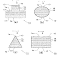
例えば、図5(a)に示すように、積層ラベル10が、平面視略凸形状に形成されている形態、同図(b)に示すように、積層ラベル10が、平面視略楕円形状(又は円形状)に形成されている形態、同図(c)に示すように、積層ラベル10が、平面視略三角形に形成されている形態、同図(d)に示すように、積層ラベル10が、両側部が波状に形成されている平面視略矩形状に形成されている形態、などを例示できる。
これら各平面形状に形成された積層ラベルは、いずれも第1フィルム1の一方向Xに延びる剥離層15と粘着層16が他方向Yに交互に設けられており、該剥離層15と粘着層16に、第2フィルム2の粘着層26と剥離層16が対面しており、前記第1フィルム1の他方向両側部1a,1b及び第2フィルム2の他方向両側部2a,2bに、一方向Xに延びる感熱接着層17,27が設けられている。
図5は、第1フィルムの表面側から見た平面図であるため、第1フィルム及び第2フィルムの層間に設けられた上記剥離層などを原則として図示できないが、第1フィルム及び第2フィルムに設けられた剥離層、粘着層及び感熱接着層の範囲を判り易く図示するため、便宜上、第1フィルムの剥離層15が設けられた範囲を「網掛け」で、第1フィルムの粘着層16が設けられた範囲を「薄墨塗り」で、第1フィルムの感熱接着層17が設けられた範囲を「斜線」で表している。
Moreover, in the said embodiment, although the
For example, as shown in FIG. 5 (a), the
In each of these laminated labels formed in a planar shape, release layers 15 and
FIG. 5 is a plan view seen from the surface side of the first film, and thus the release layer and the like provided between the first film and the second film cannot be shown in principle, but the first film and the second film are not illustrated. For the sake of convenience, the range in which the
上記のような各平面形状の積層ラベル10は、上記実施形態で示した長尺状に形成された積層ラベル10を、上記各平面形状に適合するように切り取る(又は打ち抜く)ことによって得ることができる。
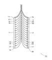
なお、例えば、図5(a)で示す平面視略凸形状の積層ラベル10の場合、図6に示すように、長尺状の積層ラベル10から、一点鎖線で示す切断線に沿って切り取ることにより、フィルムを無駄にすることなく、平面視略凸形状の積層ラベル10を得ることができる。この場合、長尺状の積層ラベル10を構成する第1フィルム1及び第2フィルムの一面の幅方向中央部に、長手方向に延びる感熱接着層17,27を設けておけばよい。
図6の平面図において、図5と同様に、第1フィルム1に設けられた感熱接着層17を「斜線」で表している。
The
For example, in the case of the
In the plan view of FIG. 6, as in FIG. 5, the heat-
1…第1フィルム、1a,1b…第1フィルムの両側部、1c…第1フィルムの一面、15…第1フィルムの剥離層、16…第1フィルムの粘着層、17…第1フィルムの感熱接着層、2…第2フィルム、2a,2b…第2フィルムの両側部、2c…第2フィルムの一面、25…第2フィルムの剥離層、26…第2フィルムの粘着層、27…第2フィルムの感熱接着層、10…積層ラベル
DESCRIPTION OF
Claims (1)
第2フィルムの一面に、前記第2フィルムの一方向に延びる剥離層と粘着層が、前記第2フィルムの他方向に交互に設けられており、
前記第1フィルムの剥離層が前記第2フィルムの粘着層に対面し、且つ前記第1フィルムの粘着層が前記第2フィルムの剥離層に対面して、前記第1フィルムと第2フィルムが剥離可能に重ね合わされている積層ラベルにおいて、
前記第1フィルムの一面の両側部に、前記第1フィルムの一方向に延びる感熱接着層が設けられ、
前記第2フィルムの一面の両側部に、前記第2フィルムの一方向に延びる感熱接着層が設けられていることを特徴とする積層ラベル。 On one surface of the first film, peeling layers and adhesive layers extending in one direction of the first film are alternately provided in the other direction of the first film,
On one surface of the second film, peeling layers and adhesive layers extending in one direction of the second film are alternately provided in the other direction of the second film,
The release layer of the first film faces the adhesive layer of the second film, the adhesive layer of the first film faces the release layer of the second film, and the first film and the second film peel off. In laminated labels that can be superimposed,
A heat-sensitive adhesive layer extending in one direction of the first film is provided on both sides of one surface of the first film,
A laminated label, wherein a heat-sensitive adhesive layer extending in one direction of the second film is provided on both sides of one surface of the second film.
Priority Applications (1)
| Application Number | Priority Date | Filing Date | Title |
|---|---|---|---|
| JP2007228500A JP5117144B2 (en) | 2007-09-04 | 2007-09-04 | Laminated label |
Applications Claiming Priority (1)
| Application Number | Priority Date | Filing Date | Title |
|---|---|---|---|
| JP2007228500A JP5117144B2 (en) | 2007-09-04 | 2007-09-04 | Laminated label |
Publications (2)
| Publication Number | Publication Date |
|---|---|
| JP2009058917A true JP2009058917A (en) | 2009-03-19 |
| JP5117144B2 JP5117144B2 (en) | 2013-01-09 |
Family
ID=40554669
Family Applications (1)
| Application Number | Title | Priority Date | Filing Date |
|---|---|---|---|
| JP2007228500A Expired - Fee Related JP5117144B2 (en) | 2007-09-04 | 2007-09-04 | Laminated label |
Country Status (1)
| Country | Link |
|---|---|
| JP (1) | JP5117144B2 (en) |
Cited By (2)
| Publication number | Priority date | Publication date | Assignee | Title |
|---|---|---|---|---|
| JP2019074561A (en) * | 2017-10-12 | 2019-05-16 | 王子ホールディングス株式会社 | Label laminate |
| JP2019074562A (en) * | 2017-10-12 | 2019-05-16 | 王子ホールディングス株式会社 | Label laminate |
Citations (5)
| Publication number | Priority date | Publication date | Assignee | Title |
|---|---|---|---|---|
| JPS4996700A (en) * | 1973-01-15 | 1974-09-12 | ||
| JPS5056655U (en) * | 1973-09-25 | 1975-05-28 | ||
| JPH041579U (en) * | 1990-04-17 | 1992-01-08 | ||
| JP2003313520A (en) * | 2002-04-24 | 2003-11-06 | Dainippon Printing Co Ltd | Adhesive sheet |
| JP2005539127A (en) * | 2002-09-18 | 2005-12-22 | スリーエム イノベイティブ プロパティズ カンパニー | Rough surface adhesive tape with thick consistent edges |
-
2007
- 2007-09-04 JP JP2007228500A patent/JP5117144B2/en not_active Expired - Fee Related
Patent Citations (5)
| Publication number | Priority date | Publication date | Assignee | Title |
|---|---|---|---|---|
| JPS4996700A (en) * | 1973-01-15 | 1974-09-12 | ||
| JPS5056655U (en) * | 1973-09-25 | 1975-05-28 | ||
| JPH041579U (en) * | 1990-04-17 | 1992-01-08 | ||
| JP2003313520A (en) * | 2002-04-24 | 2003-11-06 | Dainippon Printing Co Ltd | Adhesive sheet |
| JP2005539127A (en) * | 2002-09-18 | 2005-12-22 | スリーエム イノベイティブ プロパティズ カンパニー | Rough surface adhesive tape with thick consistent edges |
Cited By (3)
| Publication number | Priority date | Publication date | Assignee | Title |
|---|---|---|---|---|
| JP2019074561A (en) * | 2017-10-12 | 2019-05-16 | 王子ホールディングス株式会社 | Label laminate |
| JP2019074562A (en) * | 2017-10-12 | 2019-05-16 | 王子ホールディングス株式会社 | Label laminate |
| JP7047319B2 (en) | 2017-10-12 | 2022-04-05 | 王子ホールディングス株式会社 | Label laminate |
Also Published As
| Publication number | Publication date |
|---|---|
| JP5117144B2 (en) | 2013-01-09 |
Similar Documents
| Publication | Publication Date | Title |
|---|---|---|
| JP5061326B2 (en) | Roll body using thermal label | |
| JP5499934B2 (en) | Delivery slip with candy | |
| JP6040520B2 (en) | Delivery slip | |
| JP5117144B2 (en) | Laminated label | |
| JP2007003724A (en) | Winding label, and winding continued label element | |
| JP5834312B2 (en) | Tack label and labeled container | |
| JP2017219752A (en) | label | |
| JP2007199140A (en) | Continuous label sheet | |
| JP2007086595A (en) | Easy-to-peel label for separated collection | |
| JP2018114661A (en) | Manufacturing method of label base material and label | |
| JP4847368B2 (en) | Storage label | |
| JP5105950B2 (en) | Storage label | |
| JP4696494B2 (en) | Thermal label with anti-curl measures | |
| JP4901518B2 (en) | Storage label | |
| JP6585364B2 (en) | Package | |
| JP2004026377A (en) | Cylindrical film connecting method and cylindrical film | |
| JP2020032538A (en) | Laminated sheet | |
| JP2014206621A (en) | Label | |
| JP2006071857A (en) | Sticker label | |
| JP5648337B2 (en) | Delivery slip | |
| JP2001113615A (en) | Method for manufacturing label | |
| JP5009734B2 (en) | Display tag and tack sheet | |
| JP4913620B2 (en) | Storage label | |
| JP2018030307A (en) | Delivery slip | |
| JP2017134253A (en) | Easy-peeling thermosensitive resin label |
Legal Events
| Date | Code | Title | Description |
|---|---|---|---|
| A621 | Written request for application examination |
Free format text: JAPANESE INTERMEDIATE CODE: A621 Effective date: 20100810 |
|
| A977 | Report on retrieval |
Free format text: JAPANESE INTERMEDIATE CODE: A971007 Effective date: 20111129 |
|
| A131 | Notification of reasons for refusal |
Free format text: JAPANESE INTERMEDIATE CODE: A131 Effective date: 20111202 |
|
| A521 | Request for written amendment filed |
Free format text: JAPANESE INTERMEDIATE CODE: A523 Effective date: 20120120 |
|
| TRDD | Decision of grant or rejection written | ||
| A01 | Written decision to grant a patent or to grant a registration (utility model) |
Free format text: JAPANESE INTERMEDIATE CODE: A01 Effective date: 20121012 |
|
| A01 | Written decision to grant a patent or to grant a registration (utility model) |
Free format text: JAPANESE INTERMEDIATE CODE: A01 |
|
| A61 | First payment of annual fees (during grant procedure) |
Free format text: JAPANESE INTERMEDIATE CODE: A61 Effective date: 20121017 |
|
| R150 | Certificate of patent or registration of utility model |
Free format text: JAPANESE INTERMEDIATE CODE: R150 Ref document number: 5117144 Country of ref document: JP Free format text: JAPANESE INTERMEDIATE CODE: R150 |
|
| FPAY | Renewal fee payment (event date is renewal date of database) |
Free format text: PAYMENT UNTIL: 20151026 Year of fee payment: 3 |
|
| FPAY | Renewal fee payment (event date is renewal date of database) |
Free format text: PAYMENT UNTIL: 20151026 Year of fee payment: 3 |
|
| R250 | Receipt of annual fees |
Free format text: JAPANESE INTERMEDIATE CODE: R250 |
|
| R250 | Receipt of annual fees |
Free format text: JAPANESE INTERMEDIATE CODE: R250 |
|
| R250 | Receipt of annual fees |
Free format text: JAPANESE INTERMEDIATE CODE: R250 |
|
| R250 | Receipt of annual fees |
Free format text: JAPANESE INTERMEDIATE CODE: R250 |
|
| R250 | Receipt of annual fees |
Free format text: JAPANESE INTERMEDIATE CODE: R250 |
|
| R250 | Receipt of annual fees |
Free format text: JAPANESE INTERMEDIATE CODE: R250 |
|
| R250 | Receipt of annual fees |
Free format text: JAPANESE INTERMEDIATE CODE: R250 |
|
| LAPS | Cancellation because of no payment of annual fees |