JP2009056902A - Rear structure for motorcycle - Google Patents

Rear structure for motorcycle Download PDF

Info

Publication number
JP2009056902A
JP2009056902A JP2007224793A JP2007224793A JP2009056902A JP 2009056902 A JP2009056902 A JP 2009056902A JP 2007224793 A JP2007224793 A JP 2007224793A JP 2007224793 A JP2007224793 A JP 2007224793A JP 2009056902 A JP2009056902 A JP 2009056902A
Authority
JP
Japan
Prior art keywords
mudguard
license plate
license
portions
plate
Prior art date
Legal status (The legal status is an assumption and is not a legal conclusion. Google has not performed a legal analysis and makes no representation as to the accuracy of the status listed.)
Pending
Application number
JP2007224793A
Other languages
Japanese (ja)
Inventor
Michimoto Itou
理基 伊東
Current Assignee (The listed assignees may be inaccurate. Google has not performed a legal analysis and makes no representation or warranty as to the accuracy of the list.)
Honda Motor Co Ltd
Original Assignee
Honda Motor Co Ltd
Priority date (The priority date is an assumption and is not a legal conclusion. Google has not performed a legal analysis and makes no representation as to the accuracy of the date listed.)
Filing date
Publication date
Application filed by Honda Motor Co Ltd filed Critical Honda Motor Co Ltd
Priority to JP2007224793A priority Critical patent/JP2009056902A/en
Publication of JP2009056902A publication Critical patent/JP2009056902A/en
Pending legal-status Critical Current

Links

Images

Landscapes

  • Lighting Device Outwards From Vehicle And Optical Signal (AREA)

Abstract

<P>PROBLEM TO BE SOLVED: To protect a license plate while suppressing an influence given to traveling wind, and to apply design to a mud guard continuous to a rear part of a vehicle body in a motorcycle in which the mud guard covering a rear part of a rear wheel from above is continuously provided at a rear part of a rear vehicle body cover covering the rear part of the vehicle body above the rear wheel. <P>SOLUTION: A pair of right and left extension parts 19 passing through the side of the license plate 18 and extending downward is integrally provided at the rear vehicle body cover 13A so that a clearance 20 for passing the traveling wind is formed between at least an upper part of the mud guard 17A and the extension parts, lower ends of both the extension parts 19 are connected to lower ends of both right and left sides of the mud guard 17A. <P>COPYRIGHT: (C)2009,JPO&INPIT

Description

本発明は、後輪の上方で車体後部を覆う後部車体カバーの後部に、前記後輪の後部を上方から覆う泥よけが連設され、該泥よけにライセンスプレートが取付けられる自動二輪車の後部構造に関する。   The present invention provides a rear part of a motorcycle in which a mudguard covering the rear part of the rear wheel from above is connected to a rear part of a rear body cover that covers the rear part of the vehicle body above the rear wheel, and a license plate is attached to the mudguard. Concerning structure.

車体を覆う車体カバーのうち車体後部を覆う後部車体カバーの後部に、後輪の後部を上方から覆う泥よけが連設され、その泥よけにライセンスプレートが取付けられるようにした自動二輪車が、特許文献1で知られている。
特許第3770473号公報
A motorcycle in which a mudguard covering the rear part of the rear wheel from above is connected to the rear part of the rear car body cover covering the rear part of the car body cover covering the car body, and a license plate is attached to the mud guard. It is known from Patent Document 1.
Japanese Patent No. 3770473

ところで、後部車体カバーの後部が後上がりのラインを描くようにデザインすることで、外観形状がシャープな印象を与えるようにするとともに、走行時に後部車体カバーに沿った走行風を上方に向かって流すことによって空力特性を高めることが従来から行われている。しかるに後部車体カバーの後部を後上がりに形成すると、後輪が後部車体カバーから露出するために泥よけが必要となり、デザインや空力特性に与える影響を比較的少なくするために、小型の泥よけが後部車体カバーに該後部車体カバーから後方に延出するように連設され、この泥よけにライセンスプレートが取付けられるようにした自動二輪車が多い。ところが、このような自動二輪車では、ライセンスプレートが泥よけよりも大きくなり、ライセンスプレートの左右両側が泥よけからはみ出してしまい、ライセンスプレートを保護する対策が必要となる。そこでライセンスプレートの左右両側が収まるように泥よけの幅を大きくすることが考えられるが、そのようにすると、泥よけが走行風に影響を与える可能性があるだけでなく、背面視で泥よけの占める面積が増加して、車体後部と同調するようなデザインを施すことが難しかった。   By the way, by designing the rear part of the rear body cover to draw a line that rises rearward, the appearance shape gives a sharp impression and the traveling wind along the rear body cover flows upward during traveling. In order to improve the aerodynamic characteristics, it has been conventionally performed. However, if the rear part of the rear body cover is formed rearward, mud protection is required for the rear wheels to be exposed from the rear body cover, and small mud protection is required to reduce the impact on the design and aerodynamic characteristics. There are many motorcycles which are connected to the rear body cover so as to extend rearward from the rear body cover and to which a license plate is attached to prevent the mud. However, in such a motorcycle, the license plate is larger than the mudguard, and both the left and right sides of the license plate protrude from the mudguard, and a countermeasure for protecting the license plate is required. Therefore, it is conceivable to increase the width of the mudguard so that both the left and right sides of the license plate can be accommodated. The area occupied by the awning has increased, making it difficult to create a design that matches the rear of the vehicle.

本発明は、かかる事情に鑑みてなされたものであり、走行風に与える影響を少なくしつつライセンスプレートを保護し、しかも泥よけに車体後部と同調するようなデザインを施し得るようにした自動二輪車の後部構造を提供することを目的とする。   The present invention has been made in view of such circumstances, and protects the license plate while reducing the influence on the traveling wind, and is capable of applying a design that can be synchronized with the rear part of the vehicle body to prevent mud. An object is to provide a rear structure of a motorcycle.

上記目的を達成するために、請求項1記載の発明は、後輪の上方で車体後部を覆う後部車体カバーの後部に、前記後輪の後部を上方から覆う泥よけが連設され、該泥よけにライセンスプレートが取付けられる自動二輪車の後部構造において、前記後部車体カバーに、前記ライセンスプレートの側方を通って下方に延びる左右一対の延出部が、少なくとも前記泥よけの上部との間に走行風を通過せしめる隙間を形成するようにして一体に設けられ、前記両延出部の下端部が前記泥よけの左右両側下端部に接続されることを特徴とする。   In order to achieve the above object, the invention according to claim 1 is characterized in that a mudguard covering the rear part of the rear wheel from above is connected to the rear part of the rear body cover that covers the rear part of the vehicle body above the rear wheel. In the rear structure of the motorcycle to which the license plate is attached, a pair of left and right extending portions extending downward through the side of the license plate is provided at least on the mudguard. It is provided integrally so as to form a gap for allowing the traveling wind to pass there between, and the lower ends of the two extending portions are connected to the left and right lower end portions of the mudguard.

また請求項2記載の発明は、請求項1記載の発明の構成に加えて、前記泥よけの下部が、背面視では下方に開いた逆V字状となるように形成されることを特徴とする。   According to a second aspect of the invention, in addition to the structure of the first aspect of the invention, the lower part of the mudguard is formed so as to have an inverted V shape that opens downward in a rear view. And

請求項3記載の発明は、請求項1または2記載の発明の構成に加えて、前記泥よけが、側面視では前記ライセンスプレートよりも後方に該泥よけの下部を突出させるように形成され、前記ライセンスプレートよりも後方に突出している部分で前記泥よけの下部に、前記ライセンスプレートを照らすライセンスライトが配設されることを特徴とする。   According to a third aspect of the present invention, in addition to the configuration of the first or second aspect of the invention, the mudguard is formed such that a lower part of the mudguard protrudes behind the license plate in a side view. A license light for illuminating the license plate is disposed below the mudguard at a portion protruding rearward from the license plate.

請求項4記載の発明は、請求項2記載の発明の構成に加えて、前記泥よけの下部が、側面視では前記ライセンスプレートよりも後方に突出され、前記ライセンスプレートよりも後方に位置する部分で前記泥よけの下部の左右両側に、前記ライセンスプレートを照らすライセンスライトがそれぞれ配設されることを特徴とする。   According to a fourth aspect of the invention, in addition to the configuration of the second aspect of the invention, the lower portion of the mudguard protrudes rearward from the license plate in a side view and is located rearward from the license plate. The license lights for illuminating the license plate are respectively disposed on the left and right sides of the lower part of the mudguard.

さらに請求項5記載の発明は、請求項3または4記載の発明の構成に加えて、前記ライセンスライトを収納するハウジング部が前記泥よけに一体に形成されることを特徴とする。   Furthermore, the invention according to claim 5 is characterized in that, in addition to the configuration of the invention according to claim 3 or 4, a housing portion for storing the license light is integrally formed with the mudguard.

請求項1記載の発明によれば、ライセンスプレートの側方を通って下方に延びる左右一対の延出部が後部車体カバーに一体に設けられ、泥よけの左右両側下端部が前記両延出部の下端部に接続されるので、泥よけを大きくすることなく前記延出部でライセンスプレートを保護するとともに泥よけに車体後部と同調するようなデザインを施すことができ、しかも少なくとも泥よけの上部および両延出部間に、走行風を通過せしめる隙間が形成されるので、走行風の流れを抑制することがなく、空力特性に影響を与えることもない。   According to the first aspect of the present invention, the pair of left and right extending portions extending downward through the sides of the license plate are integrally provided on the rear body cover, and the left and right lower end portions of the mudguard are disposed on the both extending sides. Since the extension plate protects the license plate without increasing the mudguard, it can be designed to synchronize with the rear part of the vehicle body. Since a gap for allowing the traveling wind to pass is formed between the upper portion of the shade and the both extending portions, the flow of the traveling wind is not suppressed and the aerodynamic characteristics are not affected.

また請求項2記載の発明によれば、泥よけの下部が背面視では下方に開いた逆V字状となるので、泥よけの下部を後輪にできるだけ近接させることができ、前記隙間を通過する走行風によって後輪が巻き上げた埃が飛散するのを極力抑制することが可能であり、後輪の走行面の確認を行い易い形状にできるなど、泥よけの形状の自由度を高めることができる。   According to the second aspect of the present invention, since the lower part of the mudguard has an inverted V shape that opens downward in the rear view, the lower part of the mudguard can be as close as possible to the rear wheel, and the gap It is possible to minimize the scattering of dust rolled up by the rear wheels due to the traveling wind passing through the vehicle, and the shape of the rear wheel can be easily checked. Can be increased.

請求項3記載の発明によれば、ライセンスプレートよりも後方に突出している部分で泥よけの下部にライセンスライトが配設されることによって、ライセンスライトの照射角度の設計自由度を高めて、均一にライセンスプレートを照らすことができ、後輪がはね上げた泥等がライセンスライトに付着するのを抑制することができる。   According to the invention of claim 3, the license light is arranged at the lower part of the mudguard at the portion protruding rearward from the license plate, thereby increasing the design freedom of the irradiation angle of the license light, It is possible to illuminate the license plate evenly, and it is possible to suppress the mud and the like that the rear wheel has splashed from sticking to the license light.

請求項4記載の発明によれば、ライセンスプレートよりも後方に位置する部分で泥よけの下部の左右両側にライセンスライトがそれぞれ配設されるので、均一にライセンスプレートを照らすためのライセンスライトの効率的な配置が可能となり、また後輪がはね上げた泥等がライセンスライトに付着するのを抑制することができる。   According to the fourth aspect of the present invention, since the license lights are respectively disposed on the left and right sides of the lower part of the mudguard in the portion located behind the license plate, the license light for uniformly illuminating the license plate is provided. An efficient arrangement is possible, and mud or the like splashed by the rear wheel can be prevented from adhering to the license light.

さらに請求項5記載の発明によれば、ライセンスライトを収納するハウジング部が泥よけに一体に形成されるので、部品点数を低減することができる。   Further, according to the fifth aspect of the present invention, since the housing portion for storing the license light is integrally formed to prevent mud, the number of parts can be reduced.

以下、本発明の実施の形態を、添付の図面に示した本発明の実施例に基づいて説明する。   DESCRIPTION OF THE PREFERRED EMBODIMENTS Embodiments of the present invention will be described below based on examples of the present invention shown in the accompanying drawings.

図1〜図5は本発明の第1実施例を示すものであり、図1はスクータ型自動二輪車の左側面図、図2は図1の2矢視拡大図、図3は図2の3矢視図、図4は図3の4−4線断面図、図5は図4の5−5線拡大断面図である。   1 to 5 show a first embodiment of the present invention. FIG. 1 is a left side view of a scooter type motorcycle, FIG. 2 is an enlarged view taken along arrow 2 in FIG. 1, and FIG. 4 is a sectional view taken along line 4-4 of FIG. 3, and FIG. 5 is an enlarged sectional view taken along line 5-5 of FIG.

先ず図1において、スクータ型の自動二輪車は、操向ハンドル11によって操舵される前輪WFと、スイング式のパワーユニットPによって駆動される後輪WRとを備え、前記パワーユニットPは図示しない車体で揺動可能に支承される。前記パワーユニットPの一部および車体は車体カバー12で覆われており、この車体カバー12の一部を構成する後部車体カバー13Aが、後輪WRの上方で車体後部を覆うように形成される。   First, in FIG. 1, a scooter type motorcycle includes a front wheel WF that is steered by a steering handle 11, and a rear wheel WR that is driven by a swing type power unit P. The power unit P swings on a vehicle body (not shown). It is supported as possible. A part of the power unit P and the vehicle body are covered with a vehicle body cover 12, and a rear vehicle body cover 13A constituting a part of the vehicle body cover 12 is formed so as to cover the vehicle body rear part above the rear wheel WR.

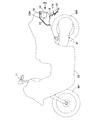
図2〜図4を併せて参照して、前記後部車体カバー13Aの後部には、ストップランプ14と、該ストップランプ14の左右両側に配置されるウインカ15,15とを備えるリヤコンビネーションランプ16が取付けられ、このリヤコンビネーションランプ16の下方で前記後部車体カバー13Aの後部には、前記後輪WRの後部を上方から覆う泥よけ17Aが連設され、該泥よけ17Aにライセンスプレート18が取付けられる。   2 to 4, a rear combination lamp 16 including a stop lamp 14 and blinkers 15 and 15 disposed on the left and right sides of the stop lamp 14 is provided at the rear part of the rear body cover 13A. A mudguard 17A that covers the rear part of the rear wheel WR from above is connected to the rear part of the rear body cover 13A below the rear combination lamp 16, and a license plate 18 is provided to the mudguard 17A. Mounted.

前記後部車体カバー13Aには、前記ライセンスプレート18の側方を通って下方に延びる左右一対の延出部19,19が、少なくとも前記泥よけ17Aの上部との間、この実施例では泥よけ17Aの全体との間に走行風を通過せしめる隙間20,20を形成するようにして一体に設けられており、前記両延出部19…の下端部は前記泥よけ17Aの左右両側下端部に接続される。   The rear body cover 13A has a pair of left and right extending portions 19, 19 extending downward through the sides of the license plate 18, at least between the upper portion of the mudguard 17A, in this embodiment mud. The lower ends of the two extension portions 19 are formed at the lower left and right lower ends of the mudguard 17A. Connected to the part.

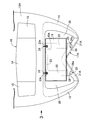
前記泥よけ17Aは、この実施例では前記後部車体カバー13Aとは別体に形成されており、下端部を前記延出部19…の下端に接続せしめて前上がりに傾斜しつつ前方に向かうにつれて相互に近接するように傾斜するとともに前端部が相互に連結される左右一対の傾斜板部21A,21Aと、それらの傾斜板部21A…の前端寄りの部分から上方に立ち上がる左右一対の立ち上がり板部22,22と、両立ち上がり板部22…の上端間を結ぶ連結板部23とを一体に備え、両立ち上がり板部22,22と、両傾斜板部21A,21Aにおいて前記立ち上がり板部22,22の連設部よりも前方の部分と、前記連結部23とで泥よけ17Aの軽量化を図るための開口部43Aが形成される。   In this embodiment, the mudguard 17A is formed separately from the rear body cover 13A, and the lower end portion is connected to the lower end of the extension portion 19 so as to incline forward and forward. The pair of left and right inclined plate portions 21A and 21A that are inclined so as to be close to each other and the front end portions thereof are connected to each other, and the pair of left and right rising plates that rise upward from a portion near the front end of the inclined plate portions 21A. Unit 22 and a connecting plate part 23 connecting the upper ends of both rising plate parts 22... Are integrally formed, and the rising plate parts 22 and 22 and the inclined plate parts 22A and 21A are provided with the rising plate parts 22 and 22A. An opening 43 </ b> A for reducing the weight of the mudguard 17 </ b> A is formed by a portion in front of the 22 connecting portions and the connecting portion 23.

前記両立ち上がり板部22…は、傾斜板部21A…よりも急角度で前上がりに傾斜しており、前記連結板部23の相互に間隔をあけた2個所に一体に突設された取付け板部23a,23aがボルト24,24によって後部車体カバー13Aに締結され、前記両傾斜板部21A…の下端は、たとえば凹凸嵌合によって前記両延出部19…の下端部に接続される。   The two rising plate portions 22 are inclined more rapidly forward than the inclined plate portions 21A, and the mounting plates integrally projecting at two positions spaced from each other of the connecting plate portion 23. The parts 23a and 23a are fastened to the rear vehicle body cover 13A by bolts 24 and 24, and the lower ends of the two inclined plate parts 21A are connected to the lower ends of the extended parts 19 by, for example, concavo-convex fitting.

ところで前記泥よけ17Aの下部、すなわち前記両傾斜板部21A…は、背面視では下方に開いた逆V字状となるものであり、ライセンスプレート18は、泥よけ17Aの両立ち上がり板部22…および連結板部23を後方から隠すようにして連結板部23に取付けられる。また泥よけ17Aに形成された軽量化のための開口部43Aもライセンスプレート18で覆われるので後方から前記開口部43Aを目視することはできない。   By the way, the lower part of the mudguard 17A, that is, both the inclined plate parts 21A ... have a reverse V shape opened downward in the rear view, and the license plate 18 has both rising plate parts of the mudguard 17A. 22 and the connecting plate portion 23 are attached to the connecting plate portion 23 so as to be hidden from the rear. Moreover, since the opening 43A for weight reduction formed in the mudguard 17A is also covered with the license plate 18, the opening 43A cannot be visually observed from the rear.

しかも前記泥よけ17Aは、側面視では前記ライセンスプレート18よりも後方に該泥よけ17Aの下部、この実施例では両傾斜板部21Aの一部を突出させるように形成され、前記ライセンスプレート18よりも後方に突出している部分で前記泥よけ17Aの下部の左右両側、この実施例では前記両傾斜板部21A…の中間部に、前記ライセンスプレート18を照らすライセンスライト25,25が配設される。   In addition, the mudguard 17A is formed so that a lower part of the mudguard 17A, in this embodiment, a part of both inclined plate portions 21A protrudes behind the license plate 18 in a side view. The license lights 25 and 25 for illuminating the license plate 18 are arranged on the left and right sides of the lower portion of the mudguard 17A in the portion protruding rearward from 18, that is, in the middle portion of the two inclined plate portions 21A in this embodiment. Established.

図5において、前記傾斜板部21A…の中間部には、下方に開いた筒状であるハウジング部26…が一体に形成されており、該ハウジング部26…の上端の閉塞部26a…は、傾斜板部21A…の上面よりも上方に膨らんだ半球状に形成され、それらの閉塞部26a…には前記ライセンスプレート18側に向かって開口した窓27…が設けられ、それらの窓27…には透光性を有するカバー28…が嵌め込まれる。   In FIG. 5, an intermediate portion of the inclined plate portion 21 </ b> A is integrally formed with a cylindrical housing portion 26 that opens downward, and a closing portion 26 a at the upper end of the housing portion 26. Formed in a hemispherical shape that swells upward from the upper surface of the inclined plate portion 21A ..., the closed portions 26a ... are provided with windows 27 ... that open toward the license plate 18 side. Is fitted with a translucent cover 28.

ライセンスライト25…は、たとえばレンズ、発光ダイオードおよび配線等をボディ29…に一体化してモジュール化されて成るものであり、前記ハウジング部26…に下方から嵌合される。しかもボディ29…の下部外周には環状の係止凹部30…が形成されており、前記ハウジング部26…の下端に一体に設けられて内方に突出する複数の係合爪31…が前記係止凹部30…に弾発的に係合することで、ライセンスライト25…がハウジング部26…に収納されるようにして該ハウジング部26…に取付けられる。   The license lights 25 are formed by modularizing, for example, lenses, light emitting diodes, wirings, and the like into the bodies 29, and are fitted into the housing portions 26 from below. In addition, an annular locking recess 30 is formed on the outer periphery of the lower portion of the body 29, and a plurality of engaging claws 31 that are integrally provided at the lower end of the housing portion 26 and protrude inward are provided in the engagement. The license lights 25 are attached to the housing portions 26 so as to be accommodated in the housing portions 26 by elastically engaging the stop recesses 30.

次にこの第1実施例の作用について説明すると、車体カバー12の一部を構成して後輪WRの上方で車体後部を覆う後部車体カバー13Aに、後輪WRを上方から覆う泥よけ17Aが連設され、該泥よけ17Aにライセンスプレート18が取付けられるのであるが、後部車体カバー13Aには、ライセンスプレート18の側方を通って下方に延びる左右一対の延出部19,19が、少なくとも前記泥よけ17Aの上部との間に走行風を通過せしめる隙間20,20を形成するようにして一体に設けられており、両延出部19…の下端部が前記泥よけ17Aの左右両側下端部部に接続されている。   Next, the operation of the first embodiment will be described. The rear body cover 13A that constitutes a part of the vehicle body cover 12 and covers the rear part of the vehicle body above the rear wheel WR, and the mudguard 17A that covers the rear wheel WR from above. The license plate 18 is attached to the mudguard 17A. The rear body cover 13A has a pair of left and right extending portions 19, 19 extending downward through the side of the license plate 18. , And at least the upper portion of the mudguard 17A are integrally provided so as to form gaps 20 and 20 through which the traveling wind can pass, and the lower ends of the two extending portions 19 are provided at the mudguard 17A. Are connected to the left and right lower end portions.

したがって泥よけ17Aを大きくすることなく前記延出部19…でライセンスプレート18を保護するとともに泥よけ17Aに車体後部と同調するようなデザインを施すことができ、しかも少なくとも泥よけ17Aの上部および両延出部19…間に、走行風を通過せしめる隙間20…が形成されるので、走行風の流れを抑制することがなく、空力特性に影響を与えることもない。   Therefore, the extension plate 19 can protect the license plate 18 without enlarging the mudguard 17A, and the mudguard 17A can be designed to synchronize with the rear part of the vehicle body. Since the clearance 20 through which the traveling wind passes is formed between the upper portion and the two extending portions 19..., The flow of the traveling wind is not suppressed and the aerodynamic characteristics are not affected.

また泥よけ17Aの下部が、背面視では下方に開いた逆V字状となるように形成されるので、泥よけ17Aの下部を後輪WRにできるだけ近接させることができ、前記隙間20…を通過する走行風によって後輪WRが巻き上げた埃が飛散するのを極力抑制することが可能であり、後輪WRの走行面の確認を行い易い形状にできるなど、泥よけ17Aの形状の自由度を高めることができる。   Further, since the lower part of the mudguard 17A is formed in an inverted V shape that opens downward in the rear view, the lower part of the mudguard 17A can be as close as possible to the rear wheel WR, and the gap 20 The shape of the mudguard 17A is such that it is possible to minimize the scattering of the dust rolled up by the rear wheel WR due to the traveling wind passing through and to make it easier to check the traveling surface of the rear wheel WR. Can increase the degree of freedom.

また泥よけ17Aが、側面視ではライセンスプレート18よりも後方に該泥よけ17Aの下部を突出させるように形成されており、ライセンスプレート18よりも後方に突出している部分で前記泥よけ17Aの下部に、前記ライセンスプレート18を照らすライセンスライト25…が配設されるので、ライセンスライト25…の照射角度の設計自由度を高めて、均一にライセンスプレート18を照らすことができ、後輪WRがはね上げた泥等がライセンスライト18に付着するのを抑制することができる。   Further, the mudguard 17A is formed so that the lower part of the mudguard 17A protrudes behind the license plate 18 in a side view, and the mudguard is projected at a portion projecting rearward from the license plate 18. Since the license light 25... For illuminating the license plate 18 is arranged at the lower part of 17A, the design freedom of the illumination angle of the license light 25 can be increased and the license plate 18 can be illuminated uniformly. It is possible to prevent mud or the like splashed by the WR from adhering to the license light 18.

しかもライセンスプレート18よりも後方に位置する部分で前記泥よけ17Aの下部の左右両側にライセンスライト25…がそれぞれ配設されるので、均一にライセンスプレート18を照らすためのライセンスライト25…の効率的な配置が可能となり、また後輪WRがはね上げた泥等がライセンスライト25…に付着するのを抑制することができる。   In addition, since the license lights 25 are disposed on the left and right sides of the lower part of the mudguard 17A at the portion located behind the license plate 18, the efficiency of the license lights 25 for uniformly illuminating the license plate 18 is provided. It is possible to prevent the mud or the like splashed by the rear wheel WR from adhering to the license lights 25.

さらにライセンスライト25…を収納するハウジング部26…が前記泥よけ17Aに一体に形成されるので、部品点数を低減することができる。   Further, since the housing portions 26 for storing the license lights 25 are integrally formed with the mudguard 17A, the number of parts can be reduced.

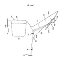
図6および図7は本発明の第2実施例を示すものであり、図6は第1実施例の図2に対応した図、図7は図6の7矢視図である。   6 and 7 show a second embodiment of the present invention. FIG. 6 corresponds to FIG. 2 of the first embodiment, and FIG. 7 is a view taken in the direction of arrow 7 in FIG.

後部車体カバー13Bの後部には、ストップランプ14およびウインカ15,15を備えるリヤコンビネーションランプ16が、該リヤコンビネーションランプ16の後側下部を後部車体カバー13Bから後方に突出させるようにして取付けられ、このリヤコンビネーションランプ16の下方で前記後部車体カバー13Bの後部には、前記後輪WRの後部を上方から覆う泥よけ17Bが連設され、該泥よけ17Bにライセンスプレート18が取付けられる。   A rear combination lamp 16 including a stop lamp 14 and turn signals 15 and 15 is attached to the rear portion of the rear body cover 13B so that the rear lower portion of the rear combination lamp 16 protrudes rearward from the rear body cover 13B. A mudguard 17B that covers the rear part of the rear wheel WR from above is connected to the rear part of the rear body cover 13B below the rear combination lamp 16, and a license plate 18 is attached to the mudguard 17B.

前記後部車体カバー13Bには、前記ライセンスプレート18の側方を通って下方に延びる左右一対の延出部19,19が、少なくとも前記泥よけ17Bの上部との間、この実施例では泥よけ17Bの全体との間に走行風を通過せしめる隙間20,20を形成するようにして一体に設けられており、前記両延出部19…の下端部は前記泥よけ17Bの左右両側下端部に接続される。   The rear body cover 13B has a pair of left and right extending portions 19, 19 extending downward through the side of the license plate 18, at least between the upper portion of the mudguard 17B, in this embodiment mud. The lower ends of the two extending portions 19 are formed at the lower left and right lower ends of the mudguard 17B. Connected to the part.

前記泥よけ17Bは、この実施例では前記後部車体カバー13Bとは別体に形成されており、下端部を前記延出部19…の下端に接続せしめて前上がりに傾斜しつつ前方に向かうにつれて相互に近接するように傾斜するとともに前端部が相互に連結される左右一対の傾斜板部21B,21Bと、それらの傾斜板部21B…の前端寄りの部分から上方に立ち上がる左右一対の立ち上がり板部22,22と、両立ち上がり板部22…の上端間を結ぶ連結板部23とを一体に備え、両立ち上がり板部22,22と、両傾斜板部21B,21Bにおいて前記立ち上がり板部22,22の連設部よりも前方の部分と、前記連結部23とで泥よけ17Bの軽量化を図るための開口部43Bが形成される。   In this embodiment, the mudguard 17B is formed separately from the rear vehicle body cover 13B, and the lower end portion is connected to the lower end of the extension portion 19 so as to incline forward and forward. The pair of left and right inclined plate portions 21B and 21B that are inclined so as to be close to each other and the front end portions are connected to each other, and the pair of left and right rising plates that rise upward from a portion near the front end of the inclined plate portions 21B. Unit 22 and a connecting plate part 23 connecting the upper ends of the two rising plate parts 22... Are integrally formed, and the rising plate parts 22, 22 and the inclined plate parts 21 B, 21 B are provided with the rising plate parts 22, 22. An opening 43 </ b> B for reducing the weight of the mudguard 17 </ b> B is formed by a portion in front of the 22 connecting portions and the connecting portion 23.

前記両立ち上がり板部22…は、傾斜板部21B…よりも急角度で前上がりに傾斜しており、前記連結板部23の相互に間隔をあけた2個所に一体に突設された取付け板部23a,23aが、ボルト24,24によって後部車体カバー13Bに締結され、前記両傾斜板部21B…の下端は、たとえば凹凸嵌合によって前記両延出部19…の下端部に接続される。   The two rising plate portions 22 are inclined more rapidly and forward than the inclined plate portions 21B, and the mounting plates integrally projecting at two positions spaced apart from each other of the connecting plate portion 23. The parts 23a, 23a are fastened to the rear vehicle body cover 13B by bolts 24, 24, and the lower ends of the two inclined plate parts 21B ... are connected to the lower ends of the extended parts 19 ... by, for example, concavo-convex fitting.

ところで前記泥よけ17Bの下部、すなわち前記両傾斜板部21B…は、背面視では下方に開いた逆V字状となるものであり、ライセンスプレート18は、泥よけ17Bの両立ち上がり板部22…および連結板部23を後方から隠すようにして連結板部23に取付けられ、泥よけ17Bに形成された軽量化のための開口部43Bもライセンスプレート18で後方から覆われる。   By the way, the lower part of the mudguard 17B, that is, both the inclined plate parts 21B... Have a reverse V shape opened downward in the rear view, and the license plate 18 has both rising plate parts of the mudguard 17B. 22 and the connecting plate portion 23 are attached to the connecting plate portion 23 so as to be hidden from the rear, and the opening 43B for weight reduction formed in the mudguard 17B is also covered with the license plate 18 from the rear.

しかも前記泥よけ17Bは、側面視では前記ライセンスプレート18よりも後方に該泥よけ17Bの下部、この実施例では両傾斜板部21Bの一部を突出させるように形成される。また前記リヤコンビネーションランプ16のストップランプ14内には、上方からライセンスプレート18を照らすライセンスライト33が配設される。   Moreover, the mudguard 17B is formed so that the lower part of the mudguard 17B, in this embodiment, a part of both inclined plate portions 21B protrudes behind the license plate 18 in a side view. A license light 33 for illuminating the license plate 18 from above is disposed in the stop lamp 14 of the rear combination lamp 16.

この第2実施例によれば、後部車体カバー13Bに、ライセンスプレート18の側方を通って下方に延びる左右一対の延出部19,19が、少なくとも泥よけ17Bの上部との間に走行風を通過せしめる隙間20,20を形成するようにして一体に設けられており、両延出部19…の下端部が泥よけ17Bの左右両側下端部部に接続されているので、泥よけ17Bを大きくすることなく前記延出部19…でライセンスプレート18を保護するとともに泥よけ17Bに車体後部と同調するようなデザインを施すことができ、しかも少なくとも泥よけ17Bの上部および両延出部19…間に、走行風を通過せしめる隙間20…が形成されるので、走行風の流れを抑制することがなく、空力特性に影響を与えることもない。   According to the second embodiment, a pair of left and right extending portions 19, 19 extending downward through the side of the license plate 18 on the rear body cover 13B travels at least between the upper portion of the mudguard 17B. Since it is provided integrally so as to form the gaps 20 and 20 through which the wind can pass, and the lower ends of both extension portions 19 are connected to the lower end portions on both the left and right sides of the mudguard 17B, mud The license plate 18 can be protected by the extension portion 19 without enlarging the cover 17B, and the mudguard 17B can be designed so as to synchronize with the rear part of the vehicle body. Since the gaps 20 for allowing the traveling wind to pass are formed between the extending portions 19..., The flow of the traveling wind is not suppressed and the aerodynamic characteristics are not affected.

また泥よけ17Bの下部が、背面視では下方に開いた逆V字状となるように形成されるので、泥よけ17Bの下部を後輪WRにできるだけ近接させることができ、前記隙間20…を通過する走行風によって後輪WRが巻き上げた埃が飛散するのを極力抑制することが可能であり、後輪WRの走行面の確認を行い易い形状にできるなど、泥よけ17Bの形状の自由度を高めることができる。   Further, since the lower part of the mudguard 17B is formed in an inverted V shape that opens downward in the rear view, the lower part of the mudguard 17B can be as close as possible to the rear wheel WR, and the gap 20 The shape of the mudguard 17B is such that it is possible to minimize the scattering of the dust rolled up by the rear wheel WR due to the traveling wind passing through, and to make it easier to check the traveling surface of the rear wheel WR. Can increase the degree of freedom.

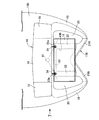
図8および図9は本発明の第3実施例を示すものであり、図8は第1実施例の図2に対応した図、図9は図8の9−9線断面図である。   8 and 9 show a third embodiment of the present invention. FIG. 8 is a view corresponding to FIG. 2 of the first embodiment, and FIG. 9 is a sectional view taken along line 9-9 of FIG.

後部車体カバー13Aの後部には、ストップランプ14およびウインカ15,15を備えるリヤコンビネーションランプ16が、該リヤコンビネーションランプ16の後側下部を後部車体カバー13Aから後方に突出させるようにして取付けられ、このリヤコンビネーションランプ16の下方で前記後部車体カバー13Aの後部には、前記後輪WRの後部を上方から覆う泥よけ17Cが連設され、該泥よけ17Cにライセンスプレート18が取付けられる。   A rear combination lamp 16 including a stop lamp 14 and turn signals 15 and 15 is attached to the rear portion of the rear body cover 13A so that the lower rear portion of the rear combination lamp 16 protrudes rearward from the rear body cover 13A. A mudguard 17C that covers the rear part of the rear wheel WR from above is connected to the rear part of the rear body cover 13A below the rear combination lamp 16, and a license plate 18 is attached to the mudguard 17C.

前記後部車体カバー13Aには、前記ライセンスプレート18の側方を通って下方に延びる左右一対の延出部19,19が、少なくとも前記泥よけ17Cの上部との間、この実施例では泥よけ17Cの全体との間に走行風を通過せしめる隙間20,20を形成するようにして一体に設けられており、前記両延出部19…の下端部は前記泥よけ17Cの左右両側下端部に接続される。   The rear body cover 13A has a pair of left and right extending portions 19, 19 extending downward through the side of the license plate 18 at least between the upper portion of the mudguard 17C, and in this embodiment mud. The lower ends of the two extending portions 19 are provided at the lower left and right lower ends of the mudguard 17C. Connected to the part.

前記泥よけ17Cは、この実施例では前記後部車体カバー13Aとは別体に形成されており、下端部を前記延出部19…の下端に接続せしめて前上がりに傾斜しつつ前方に向かうにつれて相互に近接するように傾斜する左右一対の傾斜板部21C,21Cと、それらの傾斜板部21Cの前端を相互に連結する連設部34と、前記両傾斜板部21C…の前端寄りの部分から上方に立ち上がる左右一対の立ち上がり板部22,22と、両立ち上がり板部22…の上端間を結ぶ連結板部23とを一体に備え、両立ち上がり板部22,22と、両傾斜板部21C,21Cにおいて前記立ち上がり板部22,22の連設部よりも前方の部分と、前記連結部23とで泥よけ17Cの軽量化を図るための開口部43Cが形成される。   In this embodiment, the mudguard 17C is formed separately from the rear vehicle body cover 13A, and the lower end portion is connected to the lower end of the extension portion 19 so as to incline forward and forward. The pair of left and right inclined plate portions 21C and 21C that are inclined so as to be close to each other, the connecting portion 34 that connects the front ends of the inclined plate portions 21C to each other, and the front end of the two inclined plate portions 21C. A pair of left and right rising plate portions 22 and 22 rising upward from the portion and a connecting plate portion 23 connecting the upper ends of the two rising plate portions 22... Are integrally provided, and both the rising plate portions 22 and 22 and both inclined plate portions. In 21C and 21C, an opening 43C for reducing the weight of the mudguard 17C is formed by a portion in front of the connecting portion of the rising plate portions 22 and 22 and the connecting portion 23.

前記両立ち上がり板部22…は、傾斜板部21C…よりも急角度で前上がりに傾斜しており、前記連結板部23の相互に間隔をあけた2個所に一体に突設された取付け板部23a,23aが、ボルト24,24によって後部車体カバー13Aに締結され、前記両傾斜板部21C…の下端は、たとえば凹凸嵌合によって前記両延出部19…の下端部に接続される。   The both rising plate portions 22 are inclined more rapidly and forward than the inclined plate portions 21C, and the mounting plates integrally projecting at two positions spaced apart from each other of the connecting plate portion 23. The parts 23a and 23a are fastened to the rear vehicle body cover 13A by bolts 24 and 24, and the lower ends of the two inclined plate parts 21C are connected to the lower ends of the extended parts 19 by, for example, concave-convex fitting.

ところで前記泥よけ17Cの下部、すなわち前記両傾斜板部21C…および連設部34は、背面視では下方に開いた逆V字状となるものであり、ライセンスプレート18は、泥よけ17Cの両立ち上がり板部22…および連結板部23を後方から隠すようにして連結板部23に取付けられ、泥よけ17Cに形成された軽量化のための開口部43Cもライセンスプレート18で後方から覆われる。   By the way, the lower part of the mudguard 17C, that is, both the inclined plate parts 21C... And the connecting part 34 have an inverted V shape opened downward in the rear view, and the license plate 18 has the mudguard 17C. Both the rising plate portions 22... And the connecting plate portion 23 are attached to the connecting plate portion 23 so as to be hidden from the rear, and the opening 43C for weight reduction formed in the mudguard 17C is also provided from the rear by the license plate 18. Covered.

しかも前記泥よけ17Cは、側面視では前記ライセンスプレート18よりも後方に該泥よけ17Cの下部、この実施例では両傾斜板部21Cの一部を突出させるように形成され、前記ライセンスプレート18よりも後方に突出している部分で前記泥よけ17Cの下部、この実施例では前記連設部34に、前記ライセンスプレート18を照らすライセンスライト35が配設される。   In addition, the mudguard 17C is formed so that a lower part of the mudguard 17C, in this embodiment, a part of both inclined plate portions 21C protrudes behind the license plate 18 in a side view, and the license plate A license light 35 that illuminates the license plate 18 is disposed below the mudguard 17C, in this embodiment, in the connecting portion 34, at a portion protruding rearward from 18.

図9に注目して、前記泥よけ17Cの連設部34には、下方に開いた筒状であるハウジング部36が一体に形成されており、該ハウジング部36の上端の閉塞部36aは、連設部34の上面よりも上方に膨らんだ半球状に形成され、その閉塞部36aには前記ライセンスプレート18側に向かって開口した窓37が設けられ、その窓37には透光性を有するカバー38が嵌め込まれる。   Referring to FIG. 9, the connecting portion 34 of the mudguard 17 </ b> C is integrally formed with a housing portion 36 having a cylindrical shape opened downward, and a closing portion 36 a at the upper end of the housing portion 36 is The closed portion 36a is provided with a window 37 that opens toward the license plate 18, and the window 37 has a light-transmitting property. The cover 38 which has is inserted.

ライセンスライト35は、たとえばレンズ、発光ダイオードおよび配線等をボディ39に一体化してモジュール化されて成るものであり、前記ハウジング部36に下方から嵌合される。しかもボディ39の下部外周には環状の係止凹部40が形成されており、前記ハウジング部36の下端に一体に設けられて内方に突出する複数の係合爪41…が前記係止凹部40に弾発的に係合することで、ライセンスライト35がハウジング部36に収納されるようにして該ハウジング部36に取付けられる。   The license light 35 is formed by, for example, integrating a lens, a light emitting diode, wiring, and the like into a body 39 to be modularized, and is fitted into the housing portion 36 from below. Moreover, an annular locking recess 40 is formed on the outer periphery of the lower portion of the body 39, and a plurality of engaging claws 41, which are integrally provided at the lower end of the housing portion 36 and project inward, are provided in the locking recess 40. Thus, the license light 35 is attached to the housing portion 36 so as to be accommodated in the housing portion 36.

この第3実施例によれば、後部車体カバー13Aに、ライセンスプレート18の側方を通って下方に延びる左右一対の延出部19,19が、少なくとも泥よけ17Cの上部との間に走行風を通過せしめる隙間20,20を形成するようにして一体に設けられており、両延出部19…の下端部が泥よけ17Cの左右両側下端部部に接続されているので、泥よけ17Cを大きくすることなく前記延出部19…でライセンスプレート18を保護するとともに泥よけ17Cに車体後部と同調するようなデザインを施すことができ、しかも少なくとも泥よけ17Cの上部および両延出部19…間に、走行風を通過せしめる隙間20…が形成されるので、走行風の流れを抑制することがなく、空力特性に影響を与えることもない。   According to the third embodiment, the pair of left and right extending portions 19, 19 extending downward through the side of the license plate 18 on the rear body cover 13A travels at least between the upper portion of the mudguard 17C. Since the gaps 20 and 20 that allow the wind to pass through are formed integrally, and the lower ends of both the extended portions 19 are connected to the lower left and right lower end portions of the mudguard 17C, mud The license plate 18 can be protected by the extension portion 19 without increasing the size of the cover 17C, and the mudguard 17C can be designed to synchronize with the rear of the vehicle body. Since the gaps 20 for allowing the traveling wind to pass are formed between the extending portions 19..., The flow of the traveling wind is not suppressed and the aerodynamic characteristics are not affected.

また泥よけ17Cの下部が、背面視では下方に開いた逆V字状となるように形成されるので、泥よけ17Cの下部を後輪WRにできるだけ近接させることができ、前記隙間20…を通過する走行風によって後輪WRが巻き上げた埃が飛散するのを極力抑制することが可能であり、後輪WRの走行面の確認を行い易い形状にできるなど、泥よけ17Cの形状の自由度を高めることができる。   Further, since the lower part of the mudguard 17C is formed in an inverted V shape that opens downward in the rear view, the lower part of the mudguard 17C can be as close as possible to the rear wheel WR, and the gap 20 The shape of the mudguard 17C is such that it is possible to minimize the scattering of the dust rolled up by the rear wheel WR due to the traveling wind passing through, and to make it easy to check the traveling surface of the rear wheel WR. Can increase the degree of freedom.

また泥よけ17Cが、側面視ではライセンスプレート18よりも後方に該泥よけ17Cの下部を突出させるように形成されており、ライセンスプレート18よりも後方に突出している部分で前記泥よけ17Cの下部に、前記ライセンスプレート18を照らすライセンスライト35が配設されるので、ライセンスライト35の照射角度の設計自由度を高めて、均一にライセンスプレート18を照らすことができ、後輪WRがはね上げた泥等がライセンスライト35に付着するのを抑制することができる。   Further, the mudguard 17C is formed so that the lower part of the mudguard 17C protrudes behind the license plate 18 in a side view, and the mudguard is projected at a portion projecting rearward from the license plate 18. Since the license light 35 for illuminating the license plate 18 is disposed below the 17C, the design freedom of the irradiation angle of the license light 35 can be increased, and the license plate 18 can be illuminated uniformly. It is possible to prevent the splashed mud or the like from adhering to the license light 35.

さらにライセンスライト35を収納するハウジング部36が前記泥よけ17Cに一体に形成されるので、部品点数を低減することができる。   Further, since the housing portion 36 for storing the license light 35 is integrally formed with the mudguard 17C, the number of parts can be reduced.

以上、本発明の実施例を説明したが、本発明は上記実施例に限定されるものではなく、特許請求の範囲に記載された本発明を逸脱することなく種々の設計変更を行うことが可能である。   Although the embodiments of the present invention have been described above, the present invention is not limited to the above-described embodiments, and various design changes can be made without departing from the present invention described in the claims. It is.

第1実施例のスクータ型自動二輪車の左側面図である。1 is a left side view of a scooter type motorcycle according to a first embodiment. 図1の2矢視拡大図である。FIG. 2 is an enlarged view taken along arrow 2 in FIG. 1. 図2の3矢視図である。FIG. 3 is a view taken in the direction of arrow 3 in FIG. 2. 図3の4−4線断面図である。FIG. 4 is a cross-sectional view taken along line 4-4 of FIG. 図4の5−5線拡大断面図である。FIG. 5 is an enlarged sectional view taken along line 5-5 of FIG. 第2実施例の図2に対応した図である。It is a figure corresponding to FIG. 2 of 2nd Example. 図6の7矢視図である。FIG. 7 is a view taken in the direction of arrow 7 in FIG. 6. 第3実施例の図2に対応した図である。It is a figure corresponding to FIG. 2 of 3rd Example. 図8の9−9線断面図である。FIG. 9 is a cross-sectional view taken along line 9-9 in FIG. 8.

符号の説明Explanation of symbols

13A,13B・・・後部車体カバー
17A,17B,17C・・・泥よけ
18・・・ライセンスプレート
19・・・延出部
20・・・隙間
25,35・・・ライセンスライト
26,36・・・ハウジング部
WR・・・後輪
13A, 13B ... Rear body cover 17A, 17B, 17C ... Mudguard 18 ... License plate 19 ... Extension part 20 ... Gap 25, 35 ... License light 26, 36 ..Housing part WR ... Rear wheel

Claims (5)

後輪(WR)の上方で車体後部を覆う後部車体カバー(13A,13B)の後部に、前記後輪(WR)の後部を上方から覆う泥よけ(17A,17B,17C)が連設され、該泥よけ(17A〜17C)にライセンスプレート(18)が取付けられる自動二輪車の後部構造において、前記後部車体カバー(13A,13B)に、前記ライセンスプレート(18)の側方を通って下方に延びる左右一対の延出部(19)が、少なくとも前記泥よけ(17A〜17C)の上部との間に走行風を通過せしめる隙間(20)を形成するようにして一体に設けられ、前記両延出部(19)の下端部が前記泥よけ(17A〜17C)の左右両側下端部に接続されることを特徴とする自動二輪車の後部構造。   A mudguard (17A, 17B, 17C) that covers the rear part of the rear wheel (WR) from above is connected to the rear part of the rear body cover (13A, 13B) that covers the rear part of the vehicle body above the rear wheel (WR). In the rear structure of the motorcycle in which the license plate (18) is attached to the mudguard (17A to 17C), the rear body cover (13A, 13B) is passed through the side of the license plate (18) and down. A pair of left and right extending portions (19) extending in the direction are provided integrally so as to form a gap (20) through which traveling wind passes at least between the upper portions of the mudguards (17A to 17C), A rear structure of a motorcycle, wherein lower ends of both extending portions (19) are connected to left and right lower end portions of the mudguard (17A to 17C). 前記泥よけ(17A〜17C)の下部が、背面視では下方に開いた逆V字状となるように形成されることを特徴とする請求項1記載の自動二輪車の後部構造。   The rear structure of the motorcycle according to claim 1, wherein a lower portion of the mudguard (17A to 17C) is formed in an inverted V shape opened downward in a rear view. 前記泥よけ(17A,17C)が、側面視では前記ライセンスプレート(18)よりも後方に該泥よけ(17A,17C)の下部を突出させるように形成され、前記ライセンスプレート(18)よりも後方に突出している部分で前記泥よけ(17A,17C)の下部に、前記ライセンスプレート(18)を照らすライセンスライト(25,35)が配設されることを特徴とする請求項1または2記載の自動二輪車の後部構造。   The mudguard (17A, 17C) is formed so that the lower part of the mudguard (17A, 17C) protrudes behind the license plate (18) in a side view, and from the license plate (18). A license light (25, 35) for illuminating the license plate (18) is disposed at a lower portion of the mudguard (17A, 17C) at a portion protruding rearward. The rear structure of the motorcycle according to 2. 前記泥よけ(17A)の下部が、側面視では前記ライセンスプレート(18)よりも後方に突出され、前記ライセンスプレート(18)よりも後方に位置する部分で前記泥よけ(17A)の下部の左右両側に、前記ライセンスプレート(18)を照らすライセンスライト(25)がそれぞれ配設されることを特徴とする請求項2記載の自動二輪車の後部構造。   The lower part of the mudguard (17A) protrudes rearward from the license plate (18) in a side view and is located at the rear of the license plate (18). 3. The rear structure of the motorcycle according to claim 2, wherein a license light (25) for illuminating the license plate (18) is provided on each of the left and right sides of the motorcycle. 前記ライセンスライト(25,35)を収納するハウジング部(26,36)が前記泥よけ(17A,17C)に一体に形成されることを特徴とする請求項3または4記載の自動二輪車の後部構造。   The rear part of the motorcycle according to claim 3 or 4, wherein a housing part (26, 36) for accommodating the license light (25, 35) is formed integrally with the mudguard (17A, 17C). Construction.
JP2007224793A 2007-08-30 2007-08-30 Rear structure for motorcycle Pending JP2009056902A (en)

Priority Applications (1)

Application Number Priority Date Filing Date Title
JP2007224793A JP2009056902A (en) 2007-08-30 2007-08-30 Rear structure for motorcycle

Applications Claiming Priority (1)

Application Number Priority Date Filing Date Title
JP2007224793A JP2009056902A (en) 2007-08-30 2007-08-30 Rear structure for motorcycle

Publications (1)

Publication Number Publication Date
JP2009056902A true JP2009056902A (en) 2009-03-19

Family

ID=40553058

Family Applications (1)

Application Number Title Priority Date Filing Date
JP2007224793A Pending JP2009056902A (en) 2007-08-30 2007-08-30 Rear structure for motorcycle

Country Status (1)

Country Link
JP (1) JP2009056902A (en)

Cited By (1)

* Cited by examiner, † Cited by third party
Publication number Priority date Publication date Assignee Title
JP2013075586A (en) * 2011-09-29 2013-04-25 Honda Motor Co Ltd Rear lamp structure of motorcycle

Cited By (1)

* Cited by examiner, † Cited by third party
Publication number Priority date Publication date Assignee Title
JP2013075586A (en) * 2011-09-29 2013-04-25 Honda Motor Co Ltd Rear lamp structure of motorcycle

Similar Documents

Publication Publication Date Title
JP5474732B2 (en) Front structure of saddle-ride type vehicle
US7588356B2 (en) Structure of tail light for motorcycle
US7661857B2 (en) Vehicle light unit with shadow casting feature
EP2080695B1 (en) Flasher and straddle-type vehicle
WO2009038053A1 (en) Straddle riding-type vehicle
JP2009166791A (en) Straddle type vehicle
JP2008162510A (en) Saddle ride type vehicle
JP2010030470A (en) Motorcycle
JP2009160973A (en) Motorcycle
US8256939B2 (en) Straddle-type vehicle
TW201339038A (en) Saddle-ride type vehicle
JP2010163077A (en) Tail lamp device for vehicle
JP2009040362A (en) Vehicle
JP5651025B2 (en) Headlight
JP2009056902A (en) Rear structure for motorcycle
JP4994059B2 (en) Vehicle lighting
JP5947536B2 (en) Saddle riding vehicle
JP2009208774A5 (en)
JP5468524B2 (en) Front structure of saddle-ride type vehicle
JP6192238B2 (en) Motorcycle
JP2009173220A (en) Lamp unit arrangement structure for saddle-riding type vehicle
JP2010006258A (en) Lamp and motorcycle
JP6827525B2 (en) Lighting device for saddle-mounted vehicles
JP7377648B2 (en) headlamp unit
JP6506231B2 (en) Saddle-ride type vehicle