JP2009042220A - Optical sensor device - Google Patents
Optical sensor device Download PDFInfo
- Publication number
- JP2009042220A JP2009042220A JP2008170016A JP2008170016A JP2009042220A JP 2009042220 A JP2009042220 A JP 2009042220A JP 2008170016 A JP2008170016 A JP 2008170016A JP 2008170016 A JP2008170016 A JP 2008170016A JP 2009042220 A JP2009042220 A JP 2009042220A
- Authority
- JP
- Japan
- Prior art keywords
- sensor device
- optical sensor
- light
- fresnel
- lens plate
- Prior art date
- Legal status (The legal status is an assumption and is not a legal conclusion. Google has not performed a legal analysis and makes no representation as to the accuracy of the status listed.)
- Pending
Links
- 230000003287 optical effect Effects 0.000 title claims abstract description 50
- 239000005357 flat glass Substances 0.000 claims description 28
- 238000001514 detection method Methods 0.000 claims 1
- 238000004806 packaging method and process Methods 0.000 abstract description 6
- 230000008878 coupling Effects 0.000 description 9
- 238000010168 coupling process Methods 0.000 description 9
- 238000005859 coupling reaction Methods 0.000 description 9
- 230000001154 acute effect Effects 0.000 description 2
- 239000011521 glass Substances 0.000 description 2
- 238000005286 illumination Methods 0.000 description 2
- 239000000463 material Substances 0.000 description 2
- 238000000034 method Methods 0.000 description 2
- 241000282326 Felis catus Species 0.000 description 1
- 238000010586 diagram Methods 0.000 description 1
- 238000004049 embossing Methods 0.000 description 1
- 238000011156 evaluation Methods 0.000 description 1
- 238000001746 injection moulding Methods 0.000 description 1
- 230000007257 malfunction Effects 0.000 description 1
- 238000004519 manufacturing process Methods 0.000 description 1
- 229920000515 polycarbonate Polymers 0.000 description 1
- 239000004417 polycarbonate Substances 0.000 description 1
- 230000035945 sensitivity Effects 0.000 description 1
- 229920002379 silicone rubber Polymers 0.000 description 1
- 239000004945 silicone rubber Substances 0.000 description 1
Images


Classifications
-
- B—PERFORMING OPERATIONS; TRANSPORTING
- B60—VEHICLES IN GENERAL
- B60S—SERVICING, CLEANING, REPAIRING, SUPPORTING, LIFTING, OR MANOEUVRING OF VEHICLES, NOT OTHERWISE PROVIDED FOR
- B60S1/00—Cleaning of vehicles
- B60S1/02—Cleaning windscreens, windows or optical devices
- B60S1/04—Wipers or the like, e.g. scrapers
- B60S1/06—Wipers or the like, e.g. scrapers characterised by the drive
- B60S1/08—Wipers or the like, e.g. scrapers characterised by the drive electrically driven
- B60S1/0818—Wipers or the like, e.g. scrapers characterised by the drive electrically driven including control systems responsive to external conditions, e.g. by detection of moisture, dirt or the like
- B60S1/0822—Wipers or the like, e.g. scrapers characterised by the drive electrically driven including control systems responsive to external conditions, e.g. by detection of moisture, dirt or the like characterized by the arrangement or type of detection means
- B60S1/0833—Optical rain sensor
- B60S1/0837—Optical rain sensor with a particular arrangement of the optical elements
-
- G—PHYSICS
- G01—MEASURING; TESTING
- G01J—MEASUREMENT OF INTENSITY, VELOCITY, SPECTRAL CONTENT, POLARISATION, PHASE OR PULSE CHARACTERISTICS OF INFRARED, VISIBLE OR ULTRAVIOLET LIGHT; COLORIMETRY; RADIATION PYROMETRY
- G01J1/00—Photometry, e.g. photographic exposure meter
- G01J1/02—Details
- G01J1/04—Optical or mechanical part supplementary adjustable parts
- G01J1/06—Restricting the angle of incident light
-
- G—PHYSICS
- G02—OPTICS
- G02B—OPTICAL ELEMENTS, SYSTEMS OR APPARATUS
- G02B3/00—Simple or compound lenses
- G02B3/02—Simple or compound lenses with non-spherical faces
- G02B3/08—Simple or compound lenses with non-spherical faces with discontinuous faces, e.g. Fresnel lens
-
- G—PHYSICS
- G01—MEASURING; TESTING
- G01J—MEASUREMENT OF INTENSITY, VELOCITY, SPECTRAL CONTENT, POLARISATION, PHASE OR PULSE CHARACTERISTICS OF INFRARED, VISIBLE OR ULTRAVIOLET LIGHT; COLORIMETRY; RADIATION PYROMETRY
- G01J1/00—Photometry, e.g. photographic exposure meter
- G01J1/02—Details
- G01J1/04—Optical or mechanical part supplementary adjustable parts
- G01J1/0407—Optical elements not provided otherwise, e.g. manifolds, windows, holograms, gratings
- G01J1/0411—Optical elements not provided otherwise, e.g. manifolds, windows, holograms, gratings using focussing or collimating elements, i.e. lenses or mirrors; Aberration correction
-
- G—PHYSICS
- G01—MEASURING; TESTING
- G01N—INVESTIGATING OR ANALYSING MATERIALS BY DETERMINING THEIR CHEMICAL OR PHYSICAL PROPERTIES
- G01N21/00—Investigating or analysing materials by the use of optical means, i.e. using sub-millimetre waves, infrared, visible or ultraviolet light
- G01N21/17—Systems in which incident light is modified in accordance with the properties of the material investigated
- G01N21/55—Specular reflectivity
- G01N21/552—Attenuated total reflection
-
- G—PHYSICS
- G02—OPTICS
- G02B—OPTICAL ELEMENTS, SYSTEMS OR APPARATUS
- G02B3/00—Simple or compound lenses
- G02B3/0006—Arrays
- G02B3/0037—Arrays characterized by the distribution or form of lenses
- G02B3/005—Arrays characterized by the distribution or form of lenses arranged along a single direction only, e.g. lenticular sheets
Abstract
Description
本発明は、窓ガラス、特に、自動車のフロントガラスに結合することのできる光センサ装置に関する。 The present invention relates to an optical sensor device that can be coupled to a window glass, and more particularly to a windshield of an automobile.
かかるセンサ装置は、主として、ワイパーを自動的に作動させる、自動車におけるレインセンサとして、また、車の照明灯を制御する光センサとして使用されている。 Such a sensor device is mainly used as a rain sensor in an automobile for automatically operating a wiper, and as an optical sensor for controlling an illumination lamp of a car.
欧州特許番号1 068 112 B1に開示されたレインセンサの、窓ガラスに向けて傾斜したレンズのような、光路に影響を与える古典的なレンズの使用は、比較的大きい包装スペースを必要とする。 The use of classic lenses that affect the light path, such as the lens tilted towards the window glass, of the rain sensor disclosed in European Patent No. 1 068 112 B1, requires a relatively large packaging space.
例えば、国際出願公開番号03/026937 A1から既知であるように、ホログラフィック構造体を使用することにより、より小型の構造体が可能となる。これらのセンサは、回折要素による光の回折の原理に基づくものであり、このため、有用な光の収率が遥かに小さく且つ、外部光に対する感受性が高いという主たる不利益な点がある。 For example, as is known from International Application Publication No. 03/026937 A1, the use of holographic structures allows for smaller structures. These sensors are based on the principle of light diffraction by the diffractive element, which has the main disadvantage that the yield of useful light is much smaller and the sensitivity to external light is high.
光センサ装置に関して、ドイツ国特許番号196 08 678 C1には、導光装置の光入射及び出射面をフレネルレンズとして形成することが提案されている。レンズが形成される導光装置の表面は、窓ガラスの面に対して垂直に配置されるため、この装置にて要求される包装スペースは極めて大きい。 Regarding the optical sensor device, German Patent No. 196 08 678 C1 proposes forming the light incident and exit surfaces of the light guide device as Fresnel lenses. Since the surface of the light guide device on which the lens is formed is arranged perpendicular to the surface of the window glass, the packaging space required by this device is extremely large.
本発明は、最適な光学状態下にて包装スペースを最小にする光センサ装置を提供する。 The present invention provides an optical sensor device that minimizes packaging space under optimal optical conditions.
光センサ装置の第一の型式において、送光器と、受光器と、送光器により放出された光のビームが窓ガラスに結合され、窓ガラスから非結合状態とされ且つ、受光器に向けられるようにするレンズ板とを含むセンサユニットが提供される。送光器及び受光器に面するその面にて、レンズ板は、フレネルレンズ構造体を含み、窓ガラスに面する面と反対の面にて、レンズ板は、フレネル反射器構造体を含む。この型式のものは、レインセンサとして特に有用である。この場合、センサユニットは、レンズ板内にて互いに隣接する対向したフレネル反射器構造体を有する2つの別個のフレネルレンズ構造体を備えている。1つのフレネルレンズ構造体の焦点に送光器が配設され、また、その他のレンズ構造体の焦点に受光器が配設されている。送光器から出射する光ビームは、1つのフレネル構造体により平行に整合され、レンズ板を垂直に横断し、相応するフレネル反射器構造体により窓ガラスに対して斜めに向けられ且つ、窓ガラスにより全反射され、次に、他方のフレネルレンズ構造体に属するフレネル反射器構造体よりレンズ板内に結合され且つ、レンズ板を通って垂直にその他のフレネルレンズ構造体に向けられ、これにより、受光器に集光される。全ての光学的に作用可能な要素は、レンズ板内に集中されるため、最小の包装寸法が得られる。これと同時に、窓ガラスにてセンサの大きい有用な表面が実現される。 In a first type of optical sensor device, a light transmitter, a light receiver, and a beam of light emitted by the light transmitter are coupled to the window glass, are uncoupled from the window glass, and are directed to the light receiver. There is provided a sensor unit including a lens plate to be configured. On its surface facing the transmitter and light receiver, the lens plate includes a Fresnel lens structure and on the opposite side of the surface facing the window glass, the lens plate includes a Fresnel reflector structure. This type is particularly useful as a rain sensor. In this case, the sensor unit comprises two separate Fresnel lens structures having opposed Fresnel reflector structures adjacent to each other within the lens plate. A light transmitter is disposed at the focal point of one Fresnel lens structure, and a light receiver is disposed at the focal point of the other lens structure. The light beam emanating from the transmitter is aligned in parallel by one Fresnel structure, traverses the lens plate vertically, is directed obliquely with respect to the window glass by the corresponding Fresnel reflector structure, and And then coupled into the lens plate from the Fresnel reflector structure belonging to the other Fresnel lens structure and directed vertically through the lens plate to the other Fresnel lens structure, It is condensed on the light receiver. All optically actuable elements are concentrated in the lens plate so that the smallest packaging dimensions are obtained. At the same time, a large useful surface of the sensor is realized in the window glass.
光センサ装置の第二の型式において、受光器と、窓ガラスに衝突する光ビームを窓ガラスから非結合状態にし且つ、受光器に向けるための手段であるレンズ板とを含む、センサユニットが提供される。受光器に面するその面にて、レンズ板は、フレネルレンズ構造体を有し、窓ガラスに面する面と反対の面にて、レンズ板は、フレネル反射器構造体を有する。この型式は、光センサとして特に有用である。この場合、窓ガラスに平行に衝突する光ビームは、同一の斜角度にて横断し、次に、フレネル反射器構造体によりレンズ板に結合され且つ、レンズ板を通してフレネルレンズ構造体に垂直に向けられ、これにより受光器に集光される。この場合にも、全ての光学的に作用可能な要素は、レンズ板内に集中されており、このため、最小の包装寸法が得られる。これと同時に、検出すべき光に対して優れた指向性が得られる。 In a second type of optical sensor device, a sensor unit is provided that includes a light receiver and a lens plate that is a means for decoupling the light beam impinging on the window glass from the window glass and directing it toward the light receiver. Is done. On its surface facing the light receiver, the lens plate has a Fresnel lens structure, and on the opposite side of the surface facing the window glass, the lens plate has a Fresnel reflector structure. This type is particularly useful as an optical sensor. In this case, the light beam impinging parallel to the window glass traverses at the same oblique angle, and is then coupled to the lens plate by the Fresnel reflector structure and directed perpendicularly through the lens plate to the Fresnel lens structure. Thus, the light is condensed on the light receiver. Again, all optically actuable elements are concentrated in the lens plate, so that the smallest packaging dimensions are obtained. At the same time, excellent directivity for the light to be detected is obtained.
レインセンサ/光センサの1つの望ましい実施の形態において、双方の型式の光センサ装置は、結合され且つ、全てのフレネルレンズ構造体及びフレネル反射器構造体が形成される共通のレンズ板を共用する。 In one preferred embodiment of the rain sensor / light sensor, both types of light sensor devices are combined and share a common lens plate on which all Fresnel lens structures and Fresnel reflector structures are formed. .
本発明に従った光センサ装置の更なる有利な点及び便宜な形態は、独立的な請求項から理解することができる。 Further advantages and expedient forms of the optical sensor device according to the invention can be taken from the independent claims.
本発明は、以下に、添付図面を参照して好ましい実施の形態に関して詳細に説明する。
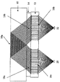
レインセンサは、典型的に、2つの同一の光センサ装置から成っている。かかるセンサ装置は、図1に概略図的に示されている。センサ装置は、自動車のフロントガラス10に取り付けられている。センサ装置の光学的に作用可能な要素は、レンズ板12である。レンズ板12は、結合層14によりフロントガラス10に光学的に結合されている。フロントガラス10から反対方向を向いたその面にて、レンズ板12には、互いに短い距離を有する2つの同一のフレネルレンズ構造体16a、16bが設けられている。フロントガラス10に面するその面にて、レンズ板12には、フレネルレンズ構造体16a、16bに対向した鏡対称のフレネル反射器構造体18a、18bが設けられている。フレネル構造体16aの焦点に送光器20が配設されている。フレネルレンズ構造体16bの焦点に受光器22が配設されている。
The present invention will now be described in detail with reference to the preferred embodiments with reference to the accompanying drawings.
A rain sensor typically consists of two identical optical sensor devices. Such a sensor device is shown schematically in FIG. The sensor device is attached to the
送光器20から出射する光のビームは、フレネルレンズ構造体16aにより平行な光に変換され、この平行な光は、レンズ板12を垂直に横断する。フレネルレンズ反射器構造体18aにより、平行な光のビームは、レンズ板12の面に対して斜めに反射され且つ、結合層14に入射する。結合層14を横断したとき、光のビームは、フロントガラス10に入射し、その対向した内面10aにて全反射される。次に、光ビームは、再度、フロントガラス10を横断し、結合層14に入射し且つ、フレネル反射器構造体18bにより偏向され、このため、光ビームは、レンズ板12を垂直に横断する。最後に、フレネルレンズ構造体16bは、平行な光ビームを収斂する光ビームに変換し、この収斂する光ビームは、受光器22に衝突する。フレネル反射器構造体は、以下に図2に関して説明する幾つかの特徴を有する。
The light beam emitted from the
フレネルレンズ構造体と同様、フレネル反射器構造体は、また、交番的に隆起し且つ傾斜する表面形態物から成っている。図2に示したように、これらの形態物は、全体として、鋸歯形状の断面をしている。第一の側面181は、基部から頂点まで真直ぐ連続的に伸びており、また、第二の側面は、2つの部分182、183から成っている。第二の側面の部分182(図2の右側)は、同様に、側面181よりも急峻である第二の部分183よりも急峻ではない。レンズ板12及び結合層14が形成される材料の屈折率n1及びn2は、鋸歯状の反射器構造体の側面における角度として、互いに慎重に調節される。レンズ板12を垂直に横断する光Lのビームは、鋭角度αにて側面181に衝突し且つ、全反射され、また、角度βにて側面182に衝突する。図2に示した実施の形態において、角度βは90°であり、このため、出射角度γもまた90°である。このように、側面182にて反射する光は無い。屈折率n1及びn2は、僅かだけ相違する。側面181における光ビームの全反射は、入射角度が屈折率の比のアークサインより大きい状態下にて生ずる。屈折率の比は、1から僅かだけ相違するため、入射角度αは、比較的平坦でなければならない。レンズ板12に対するポリカーボネート及び結合層14に対するシリコーンゴムの対について、例えば、約26°の最大の入射角度αが得られる。この角度は、反射器構造体の最小の急峻度を決定する。実際の急峻度は、フロントガラスの方向に向けて出射する光のビームは、窓ガラス上にて全反射するのに必要な角度を有していることにより決定される。窓ガラスにて全反射するために望まれる入射角度は、典型的に、約45°である。この角度は、反射器構造体の幾何学的形態に関する条件と適合可能である。
Like the Fresnel lens structure, the Fresnel reflector structure also consists of surface features that are alternately raised and inclined. As shown in FIG. 2, these features generally have a saw-tooth shaped cross section. A
図3aには、再度、図2に示したようなフレネル反射器構造体の幾何学的形態にて実現可能な光の誘導状態が概略図に示されている。レンズ板12と結合層14との間の境界面にて反射する光は無い。その結果、フロントガラス10の全反射面より形成されたセンサ面の照明程度は最適でなくなる。
FIG. 3 a shows a schematic diagram of the light guiding state which can be realized again with the geometry of the Fresnel reflector structure as shown in FIG. There is no light reflected at the interface between the
図3bに示した状態は、更により好ましくない。この図において、鋸歯構造体の右側面における部分182は、より平坦である。光のビームは、90°以外の角度にて側面182に衝突するため、光の屈折は、数学的に負の方向(図3の右側)に向けて生じる。出射する光ビームは、図3aにおけるよりも更に狭い。図3cに示した幾何学的形態にて最適な状態が得られる。この場合、この図面の右側にて示した鋸歯構造体の側面は、連続的であり、また、左側面よりも急峻に設定される。右側面において、光の屈折は、数学的に正の方向(図3cの左側)に向けて行なわれる。左側面への光ビームの衝突角度は、全反射のための状態と適合可能である。右側面にて屈折した光ビームは、隣接する鋸歯構造体の頂点に接触する。その結果、フロントガラスにおけるセンサ面は妨害されずに照明される。
The situation shown in FIG. 3b is even less preferred. In this figure,
フレネル反射器構造体のこの実施の形態が適正に機能するためには、結合層14の材料が気泡又は同様のものを何ら含むことなく、反射器構造体の面に対して確実に休止する必要がある。
In order for this embodiment of the Fresnel reflector structure to function properly, the material of the
図4に示した光センサ装置の実施の形態は、方向感応型光センサである。図示したセンサ装置は、この場合にも、光学要素としてレンズ板12を有しており、該レンズ板は、この場合、フレネルレンズ構造体16のみを有し、また、該フレネルレンズ構造体に対向して相応するフレネル反射器構造体18を含む。受光器22がフレネルレンズ構造体16の焦点に配置されている。結合層14によって、レンズ板はその傾斜角度が図示した実施の形態において約27°であるフロントガラス10に結合されている。フレネル反射器構造体18の幾何学的形態に対し、図1に示したレインセンサの実施の形態と同一の基準が同様に当て嵌まる。光センサは、フロントガラス10に水平に衝突する光に対して感応性があり、該光は、窓ガラスに衝突するとき、斜め下方に屈折され、また、結合層14を通ってフレネル反射器構造体18に衝突し、該フレネル反射器構造体は、光ビームを偏向させ且つその光ビームをレンズ板12を通して垂直にフレネルレンズ構造体16に向け、該フレネルレンズ構造体16は、その光を受光器22に集光させる。
The embodiment of the optical sensor device shown in FIG. 4 is a direction-sensitive optical sensor. The illustrated sensor device again has a
実際上、組み合わせたレインセンサ/光センサが必要とされる。レインセンサは、図1に示した型式の2つの同一のセンサ装置を含む。受光器によって供給された信号に差を形成することにより、信号の評価が実行される。2つのセンサ装置は、互いに隣接して配置され且つ、共通のレンズ板を共用する。同一のレンズ板は、図4に示した光センサの光学的に作用可能な構造体を含む。必要である場合、異なる方向からの光を受け取ることができる更なるセンサが提供される。方向不定の周囲光をレンズ板12の光学的に不作用又は非活性領域を通じて更に検出することができる。
In practice, a combined rain / light sensor is required. The rain sensor includes two identical sensor devices of the type shown in FIG. Signal evaluation is performed by forming a difference in the signal supplied by the light receiver. The two sensor devices are arranged adjacent to each other and share a common lens plate. The same lens plate includes the optically operable structure of the optical sensor shown in FIG. If necessary, additional sensors are provided that can receive light from different directions. Undirected ambient light can be further detected through the optically inactive or inactive region of the
レンズ板12の製造は、従来の射出成形技術によって実行することができる。これ代替的に、エンボス加工技術を使用してもよい。
望ましくない光との結合及び(又は)非結合状態による何らかの誤作動を回避するため、レンズ板の光学的に不作用面には、例えば、後方反射器要素(いわゆるキャッツアイ)のような屈折性又は反射性構造体が設けられる。これにより、光学的に作用可能な面に衝突しない光は、「無害」の方向に向けて偏向される。
The manufacture of the
In order to avoid any malfunctions due to undesired coupling and / or uncoupling conditions, the optically inactive surface of the lens plate has a refractive property, for example a back reflector element (so-called cat's eye). Alternatively, a reflective structure is provided. Thereby, light that does not collide with an optically actuable surface is deflected in a “harmless” direction.
10 フロントガラス
10a フロントガラス10の対向した内面
12 レンズ板
14 結合層
16a フレネルレンズ構造体
16b フレネルレンズ構造体
18a フレネル反射器構造体
181 第一の側面
182 第二の側面の部分
183 第二の側面の部分
18b フレネル反射器構造体
20 送光器
22 受光器
n1 屈折率
n2 屈折率
α 鋭角度/入射角度
β 角度
γ 出射角度
DESCRIPTION OF
Claims (17)
送光器と、受光器と、送光器により放出された光のビームを窓ガラスに結合し且つビームを窓ガラスから非結合状態にし、また、ビームを受光器に向けるレンズ板とを備えるセンサユニットであって、レンズ板は、送光器及び受光器に面し、また、フレネルレンズ構造体が設けられた面と、窓ガラスに面し且つフレネル反射器構造体が設けられた対向した面とを有する前記センサユニットを備える、光センサ装置。 In an optical sensor device adapted to be coupled to a window glass, in particular a car windshield,
A sensor comprising a light transmitter, a light receiver, and a lens plate that couples the beam of light emitted by the light transmitter to the window glass, uncouples the beam from the window glass, and directs the beam to the light receiver The unit is a unit, the lens plate faces the transmitter and the receiver, the surface provided with the Fresnel lens structure, and the opposite surface facing the window glass and provided with the Fresnel reflector structure An optical sensor device comprising the sensor unit having:
受光器と、窓ガラスに衝突する光のビームを窓ガラスから非結合状態にし、また、ビームを受光器に向けるレンズ板とを備えるセンサユニットであって、レンズ板は、受光器に面し、また、フレネルレンズ構造体が設けられた面と、窓ガラスに面し且つフレネル反射器構造体が設けられた対向した面とを有する前記センサユニットを備える、光センサ装置。 In an optical sensor device adapted to be coupled to a window glass, in particular a car windshield,
A sensor unit comprising a light receiver and a lens plate that causes the beam of light impinging on the window glass to be uncoupled from the window glass and directs the beam to the light receiver, the lens plate facing the light receiver, An optical sensor device comprising the sensor unit having a surface provided with a Fresnel lens structure and an opposed surface facing a window glass and provided with a Fresnel reflector structure.
反射器構造体が設けられたレンズ板の面は、反射器構造体に対して確実に休止する結合層により窓ガラスに結合される、光センサ装置。 The optical sensor device according to claim 1 or 2,
The optical sensor device, wherein the surface of the lens plate provided with the reflector structure is bonded to the window glass by a bonding layer that reliably rests with respect to the reflector structure.
フレネル反射器構造体は内面にて反射する、光センサ装置。 In the optical sensor device according to any one of claims 1 to 3,
An optical sensor device in which the Fresnel reflector structure reflects on the inner surface.
レンズ板は、フレネルレンズ構造体の側部における収斂する光ビームをフレネル反射器構造体の側部における平行な光ビームに変換し、また、その逆に変換する、光センサ装置。 In the optical sensor device according to any one of claims 1 to 4,
The lens plate is an optical sensor device that converts a converging light beam at the side of the Fresnel lens structure into a parallel light beam at the side of the Fresnel reflector structure and vice versa.
平行な光ビームは、前記面に対して垂直にレンズ板を横断する、光センサ装置。 The optical sensor device according to claim 5,
An optical sensor device in which a parallel light beam traverses a lens plate perpendicular to the plane.
平行な光ビームは、レンズ板の前記面に対して斜めに傾斜している、光センサ装置。 The optical sensor device according to claim 6.
The parallel light beam is inclined with respect to the surface of the lens plate.
レンズ板の外側にて、平行な光ビームは、前記面に対して約45°の角度にて傾斜している、光センサ装置。 The optical sensor device according to claim 6.
An optical sensor device in which a parallel light beam is inclined at an angle of about 45 ° with respect to the surface outside the lens plate.
フレネル反射器構造体は、反射光が衝突する第一の側面と、平行な光ビームが入射し又は出射する第二の側面とを有する、全体として、鋸歯形状の断面である、光センサ装置。 The optical sensor device according to any one of claims 1 to 8,
The Fresnel reflector structure is an optical sensor device having a first side surface on which reflected light collides and a second side surface on which a parallel light beam enters or exits, and has a sawtooth-shaped cross section as a whole.
フレネル反射器構造体の第二の側面は、垂直に横断される、光センサ装置。 The optical sensor device according to claim 9.
The optical sensor device, wherein the second side of the Fresnel reflector structure is traversed vertically.
フレネル反射器構造体の第二の側面にて光の屈折が行なわれる、光センサ装置。 The optical sensor device according to claim 9.
An optical sensor device in which light is refracted at a second side of the Fresnel reflector structure.
フレネル反射器構造体の第二の側面は、2つの異なる急峻な部分から成り、該各部分のうちより急峻でない部分は、入射面又は出射面を形成する、光センサ装置。 The optical sensor device according to claim 10 or 11,
The optical sensor device, wherein the second side surface of the Fresnel reflector structure is composed of two different steep portions, and the less steep portion of each portion forms an entrance surface or an exit surface.
フレネル反射器構造体の第二の側面は、第一の側面よりも急峻な入射面又は出射面を形成する、光センサ装置。 The optical sensor device according to claim 11.
The optical sensor device, wherein the second side surface of the Fresnel reflector structure forms a steeper incident surface or outgoing surface than the first side surface.
互いに隣接してレンズ板に形成された対向したフレネル反射器構造体を有する2つの別個のフレネルレンズ構造体を含む少なくとも1つのセンサユニットを備え、
送光器は、前記フレネルレンズ構造体の第一の構造体の焦点内に配設され、受光器は、前記フレネルレンズ構造体の第二の構造体の焦点内に配設され、
送光器から出射する光のビームは、レンズ板を垂直に横断して第一のフレネルレンズ構造体により平行に整合され、また、相応するフレネル反射器構造体により窓ガラスに対して斜めに向けられると共に、窓ガラスにより全反射され、次に、第二のフレネルレンズ構造体に属するフレネル反射器構造体によりレンズ板に結合され、また、レンズ板を通して垂直に第二のフレネルレンズ構造体に向けられ且つ該第二のフレネルレンズ構造体より受光器にて集光される、光センサ装置。 In the optical sensor device according to any one of claims 1 or 3 to 13,
Comprising at least one sensor unit comprising two separate Fresnel lens structures having opposed Fresnel reflector structures formed on the lens plate adjacent to each other;
A light transmitter is disposed in the focal point of the first structure of the Fresnel lens structure, and a light receiver is disposed in the focal point of the second structure of the Fresnel lens structure;
The beam of light emanating from the transmitter is aligned parallel to the first Fresnel lens structure perpendicularly across the lens plate and directed obliquely with respect to the window glass by the corresponding Fresnel reflector structure. And is totally reflected by the window glass and then coupled to the lens plate by a Fresnel reflector structure belonging to the second Fresnel lens structure and also directed vertically through the lens plate to the second Fresnel lens structure. And a light sensor device that collects light from the second Fresnel lens structure by a light receiver.
共通のレンズ板を有する偶数のセンサユニットを含む、光センサ装置。 The optical sensor device according to claim 14.
An optical sensor device comprising an even number of sensor units having a common lens plate.
狭小な検出角度にて窓ガラスに衝突する光のビームは、窓ガラスを斜めに横断し、次に、フレネル反射器構造体によりレンズ板に結合され且つ、レンズ板を通してフレネルレンズ構造体に垂直に向けられ、これにより受光器の上にて集光される、光センサ装置。 In the optical sensor device according to any one of claims 2 and 3 to 13,
The beam of light impinging on the window glass at a narrow detection angle crosses the window glass diagonally, and is then coupled to the lens plate by the Fresnel reflector structure and perpendicular to the Fresnel lens structure through the lens plate. An optical sensor device that is directed and thereby collected on a light receiver.
Applications Claiming Priority (1)
| Application Number | Priority Date | Filing Date | Title |
|---|---|---|---|
| DE102007036492A DE102007036492B4 (en) | 2007-08-01 | 2007-08-01 | Optical sensor device |
Related Child Applications (1)
| Application Number | Title | Priority Date | Filing Date |
|---|---|---|---|
| JP2010225491A Division JP5156072B2 (en) | 2007-08-01 | 2010-10-05 | Optical sensor device |
Publications (2)
| Publication Number | Publication Date |
|---|---|
| JP2009042220A true JP2009042220A (en) | 2009-02-26 |
| JP2009042220A5 JP2009042220A5 (en) | 2010-05-20 |
Family
ID=39831872
Family Applications (2)
| Application Number | Title | Priority Date | Filing Date |
|---|---|---|---|
| JP2008170016A Pending JP2009042220A (en) | 2007-08-01 | 2008-06-30 | Optical sensor device |
| JP2010225491A Expired - Fee Related JP5156072B2 (en) | 2007-08-01 | 2010-10-05 | Optical sensor device |
Family Applications After (1)
| Application Number | Title | Priority Date | Filing Date |
|---|---|---|---|
| JP2010225491A Expired - Fee Related JP5156072B2 (en) | 2007-08-01 | 2010-10-05 | Optical sensor device |
Country Status (7)
| Country | Link |
|---|---|
| US (1) | US7804055B2 (en) |
| EP (1) | EP2020348B1 (en) |
| JP (2) | JP2009042220A (en) |
| CN (1) | CN101359059B (en) |
| BR (1) | BRPI0803750A2 (en) |
| DE (1) | DE102007036492B4 (en) |
| MX (1) | MX2008009889A (en) |
Families Citing this family (26)
| Publication number | Priority date | Publication date | Assignee | Title |
|---|---|---|---|---|
| DE102007025987A1 (en) | 2007-06-04 | 2009-01-08 | Trw Automotive Electronics & Components Gmbh | Optical sensor device for detecting wetting |
| DE102008020171B4 (en) | 2008-04-22 | 2010-08-05 | Trw Automotive Electronics & Components Gmbh | Optical sensor device |
| DE102008023845B4 (en) | 2008-05-16 | 2018-04-05 | Trw Automotive Electronics & Components Gmbh | Optical sensor device for detecting ambient light |
| DE102008033204A1 (en) | 2008-07-15 | 2010-02-04 | Trw Automotive Electronics & Components Gmbh | Optical sensor |
| DE102009053825A1 (en) | 2009-11-18 | 2011-05-19 | Trw Automotive Electronics & Components Gmbh | Optical sensor device for detecting ambient light |
| CN102401318A (en) * | 2010-09-10 | 2012-04-04 | 欧司朗有限公司 | Lens processing method and lens |
| CN102621618B (en) * | 2011-01-27 | 2016-03-09 | 鸿富锦精密工业(深圳)有限公司 | Light-strip and light-emitting device |
| DE102011108683A1 (en) | 2011-07-27 | 2013-01-31 | Valeo Schalter Und Sensoren Gmbh | Optical measuring device for a vehicle |
| JP5761143B2 (en) * | 2011-11-02 | 2015-08-12 | 株式会社リコー | Imaging unit, vehicle equipped with imaging unit |
| DE102013009126A1 (en) * | 2013-05-30 | 2014-12-04 | Hella Kgaa Hueck & Co. | sensor device |
| DE102015008298A1 (en) * | 2015-06-29 | 2016-12-29 | Hella Kgaa Hueck & Co. | Sensor device for detecting moisture on a pane and motor vehicle |
| DE102015117266B4 (en) * | 2015-10-09 | 2017-07-13 | Trw Automotive Electronics & Components Gmbh | Lens component of a rain sensor and modular system, method and tool for manufacturing |
| DE102015013097A1 (en) * | 2015-10-12 | 2017-04-13 | Hella Kgaa Hueck & Co. | Sensor device for determining environmental conditions of a vehicle, in particular of a motor vehicle, and method for determining the position of the sun |
| CN107179567A (en) * | 2016-03-11 | 2017-09-19 | 武汉拉法叶科技有限责任公司 | Automobile-used rain sensor and its optical lens |
| US20180045933A1 (en) * | 2016-06-30 | 2018-02-15 | Danielle Dileo | Optical system for an led wash luminaire |
| CN106353840A (en) * | 2016-08-31 | 2017-01-25 | 天合汽车零部件(苏州)有限公司 | Rain sensor based on Fresnel lens |
| DE102017101655B4 (en) | 2017-01-27 | 2024-01-25 | Bcs Automotive Interface Solutions Gmbh | Electro-optic assembly and method for detecting ambient light |
| DE102017122444B4 (en) * | 2017-09-27 | 2022-06-15 | Bcs Automotive Interface Solutions Gmbh | Lens plate, rain sensor and light sensor |
| US10516216B2 (en) | 2018-01-12 | 2019-12-24 | Eagle Technology, Llc | Deployable reflector antenna system |
| KR102563912B1 (en) * | 2018-04-02 | 2023-08-07 | 삼성전자주식회사 | The Electronic Device Including the Optical Sensor using the Fresnel lens |
| DE102018119412B4 (en) * | 2018-08-09 | 2023-03-30 | Bcs Automotive Interface Solutions Gmbh | Optical assembly and method for manufacturing an optical assembly |
| US11001979B2 (en) | 2018-08-13 | 2021-05-11 | Vergence Automation, Inc. | Methods and apparatus for ultrawide entrance angle reflective articles for use with autonomous vehicle machine vision systems |
| US10707552B2 (en) | 2018-08-21 | 2020-07-07 | Eagle Technology, Llc | Folded rib truss structure for reflector antenna with zero over stretch |
| US11762133B1 (en) | 2018-09-13 | 2023-09-19 | Vergence Automation, Inc. | Retroreflective materials and articles incorporating near-ideal total internal retroreflective elements |
| KR102121398B1 (en) | 2018-10-29 | 2020-06-10 | 니덱모빌리티코리아 주식회사 | Rain Sensor Module with Aspherical Lens |
| CN110132904B (en) * | 2019-05-24 | 2021-06-29 | 上海世雨智能科技有限公司 | Optical structure for detecting dynamic and static rain and snow in vehicle-mounted sensor |
Citations (14)
| Publication number | Priority date | Publication date | Assignee | Title |
|---|---|---|---|---|
| JPS59144585U (en) * | 1983-03-17 | 1984-09-27 | オプテックス株式会社 | Infrared moving object detection device |
| JPS6338270A (en) * | 1986-08-04 | 1988-02-18 | Omron Tateisi Electronics Co | Light emitting and receiving device |
| JPH04147019A (en) * | 1990-10-11 | 1992-05-20 | Nippon Arefu:Kk | Optical sensor |
| JPH05150299A (en) * | 1991-02-27 | 1993-06-18 | Konica Corp | Flashing device and camera provided therewith |
| JPH1194731A (en) * | 1997-07-22 | 1999-04-09 | Nippon Sheet Glass Co Ltd | Transparent substrate having liquid detecting function |
| JP2000136998A (en) * | 1998-11-02 | 2000-05-16 | Central Glass Co Ltd | Raindrop detecting device |
| JP2001066246A (en) * | 1999-08-27 | 2001-03-16 | Denso Corp | Raindrop sensor |
| JP2002534705A (en) * | 1998-12-31 | 2002-10-15 | マイクロシャープ コーポレイション リミテッド | Diffuser with stepped surface |
| JP2002536638A (en) * | 1999-02-01 | 2002-10-29 | ヴィーア・アクティーゼルスカブ | Surface plasmon resonance sensor |
| JP2003254897A (en) * | 2002-02-28 | 2003-09-10 | Denso Corp | Apparatus for detecting rain drop and automatic wiper apparatus |
| JP2004516492A (en) * | 1999-05-14 | 2004-06-03 | マイクロシャープ コーポレイション リミテッド | Display and light transmission plate for display |
| JP2005512048A (en) * | 2001-11-27 | 2005-04-28 | ローベルト ボツシユ ゲゼルシヤフト ミツト ベシユレンクテル ハフツング | A rain sensor especially used in automobiles |
| JP2006071491A (en) * | 2004-09-02 | 2006-03-16 | Denso Corp | Raindrop detecting apparatus |
| JP2006119032A (en) * | 2004-10-22 | 2006-05-11 | Stanley Electric Co Ltd | Drift correcting method of optical raindrop sensor |
Family Cites Families (11)
| Publication number | Priority date | Publication date | Assignee | Title |
|---|---|---|---|---|
| JPS59144585A (en) | 1983-02-07 | 1984-08-18 | Origin Electric Co Ltd | Projection welding method |
| JPH0623817B2 (en) * | 1985-07-18 | 1994-03-30 | 旭光学工業株式会社 | LCD projection image display device |
| DE4318114C2 (en) * | 1993-06-01 | 1998-07-16 | Kostal Leopold Gmbh & Co Kg | Sensor device |
| DE19701258A1 (en) * | 1996-01-18 | 1997-07-24 | Itt Mfg Enterprises Inc | Rain sensing system for transparent material surfaces e.g. windscreens |
| DE19608648C1 (en) * | 1996-03-06 | 1997-10-23 | Bosch Gmbh Robert | Device for detecting wetting events on a pane |
| DE19821335C2 (en) * | 1997-04-04 | 2000-07-13 | Kostal Leopold Gmbh & Co Kg | Optoelectronic sensor device |
| DE19830120B4 (en) * | 1997-07-09 | 2006-07-06 | Leopold Kostal Gmbh & Co. Kg | Optoelectronic sensor device |
| US5898183A (en) * | 1997-10-16 | 1999-04-27 | Libbey-Owens-Ford Co. | Compact moisture sensor with efficient high obliquity optics |
| US7236249B1 (en) * | 1998-04-08 | 2007-06-26 | Robert Bosch Gmbh | Rain sensor |
| DE10147447A1 (en) * | 2001-09-26 | 2003-04-17 | Bosch Gmbh Robert | Holographic sensor, in particular for detecting moisture on a window of a motor vehicle |
| DE102004033734A1 (en) * | 2004-07-13 | 2006-02-02 | Leopold Kostal Gmbh & Co. Kg | Optoelectronic sensor device for a motor vehicle |
-
2007
- 2007-08-01 DE DE102007036492A patent/DE102007036492B4/en active Active
-
2008
- 2008-06-20 EP EP08011287.3A patent/EP2020348B1/en active Active
- 2008-06-30 JP JP2008170016A patent/JP2009042220A/en active Pending
- 2008-07-16 BR BRPI0803750-7A patent/BRPI0803750A2/en not_active Application Discontinuation
- 2008-07-21 US US12/220,002 patent/US7804055B2/en active Active
- 2008-07-29 CN CN2008101441010A patent/CN101359059B/en active Active
- 2008-07-31 MX MX2008009889A patent/MX2008009889A/en active IP Right Grant
-
2010
- 2010-10-05 JP JP2010225491A patent/JP5156072B2/en not_active Expired - Fee Related
Patent Citations (14)
| Publication number | Priority date | Publication date | Assignee | Title |
|---|---|---|---|---|
| JPS59144585U (en) * | 1983-03-17 | 1984-09-27 | オプテックス株式会社 | Infrared moving object detection device |
| JPS6338270A (en) * | 1986-08-04 | 1988-02-18 | Omron Tateisi Electronics Co | Light emitting and receiving device |
| JPH04147019A (en) * | 1990-10-11 | 1992-05-20 | Nippon Arefu:Kk | Optical sensor |
| JPH05150299A (en) * | 1991-02-27 | 1993-06-18 | Konica Corp | Flashing device and camera provided therewith |
| JPH1194731A (en) * | 1997-07-22 | 1999-04-09 | Nippon Sheet Glass Co Ltd | Transparent substrate having liquid detecting function |
| JP2000136998A (en) * | 1998-11-02 | 2000-05-16 | Central Glass Co Ltd | Raindrop detecting device |
| JP2002534705A (en) * | 1998-12-31 | 2002-10-15 | マイクロシャープ コーポレイション リミテッド | Diffuser with stepped surface |
| JP2002536638A (en) * | 1999-02-01 | 2002-10-29 | ヴィーア・アクティーゼルスカブ | Surface plasmon resonance sensor |
| JP2004516492A (en) * | 1999-05-14 | 2004-06-03 | マイクロシャープ コーポレイション リミテッド | Display and light transmission plate for display |
| JP2001066246A (en) * | 1999-08-27 | 2001-03-16 | Denso Corp | Raindrop sensor |
| JP2005512048A (en) * | 2001-11-27 | 2005-04-28 | ローベルト ボツシユ ゲゼルシヤフト ミツト ベシユレンクテル ハフツング | A rain sensor especially used in automobiles |
| JP2003254897A (en) * | 2002-02-28 | 2003-09-10 | Denso Corp | Apparatus for detecting rain drop and automatic wiper apparatus |
| JP2006071491A (en) * | 2004-09-02 | 2006-03-16 | Denso Corp | Raindrop detecting apparatus |
| JP2006119032A (en) * | 2004-10-22 | 2006-05-11 | Stanley Electric Co Ltd | Drift correcting method of optical raindrop sensor |
Also Published As
| Publication number | Publication date |
|---|---|
| CN101359059A (en) | 2009-02-04 |
| MX2008009889A (en) | 2009-02-27 |
| US7804055B2 (en) | 2010-09-28 |
| JP5156072B2 (en) | 2013-03-06 |
| EP2020348B1 (en) | 2016-08-10 |
| EP2020348A3 (en) | 2010-11-03 |
| US20090032689A1 (en) | 2009-02-05 |
| DE102007036492A1 (en) | 2009-02-05 |
| EP2020348A2 (en) | 2009-02-04 |
| CN101359059B (en) | 2010-12-01 |
| JP2011080995A (en) | 2011-04-21 |
| DE102007036492B4 (en) | 2009-07-30 |
| BRPI0803750A2 (en) | 2009-10-06 |
Similar Documents
| Publication | Publication Date | Title |
|---|---|---|
| JP5156072B2 (en) | Optical sensor device | |
| JP4929308B2 (en) | Optical sensor device | |
| JP4986936B2 (en) | Optical sensor device and method of manufacturing optical sensor device | |
| JP5867979B2 (en) | Optical sensor device for detecting ambient light | |
| EP2196793B1 (en) | Optical sensor device | |
| KR100469605B1 (en) | Compact moisture detector with collimator lens and spectrocouple | |
| US6507015B1 (en) | Raindrop sensor having plano-convex lens | |
| JP4637907B2 (en) | Photoelectric sensor device for automobile | |
| US20070235638A1 (en) | Optical sensor device | |
| KR100829409B1 (en) | Sensing device for detecting wetness on a window | |
| US20170182978A1 (en) | Lens plate | |
| US20120267514A1 (en) | Optical sensing device for detecting ambient light in motor vehicles | |
| KR101101538B1 (en) | Optical sensor device | |
| JP4826620B2 (en) | Photodetector | |
| JP2002505755A (en) | Sensor device for detecting wet state of glass plate such as wind glass | |
| US6627910B2 (en) | Precipitation sensor | |
| JP2002534662A (en) | Detector for detecting dirt on the transparent plate surface | |
| JP2021056064A (en) | Droplet sensor | |
| CN210465732U (en) | Lens, sensor assembly and vehicle | |
| JPH09304609A (en) | Light intensity distribution control element, and light projection device and photoelectric sensor using the same | |
| JPS61294336A (en) | Water drop detector |
Legal Events
| Date | Code | Title | Description |
|---|---|---|---|
| A977 | Report on retrieval |
Free format text: JAPANESE INTERMEDIATE CODE: A971007 Effective date: 20090721 |
|
| A131 | Notification of reasons for refusal |
Free format text: JAPANESE INTERMEDIATE CODE: A131 Effective date: 20090727 |
|
| A601 | Written request for extension of time |
Free format text: JAPANESE INTERMEDIATE CODE: A601 Effective date: 20091026 |
|
| A602 | Written permission of extension of time |
Free format text: JAPANESE INTERMEDIATE CODE: A602 Effective date: 20091029 |
|
| A524 | Written submission of copy of amendment under section 19 (pct) |
Free format text: JAPANESE INTERMEDIATE CODE: A524 Effective date: 20091030 |
|
| A521 | Written amendment |
Free format text: JAPANESE INTERMEDIATE CODE: A821 Effective date: 20091030 |
|
| A131 | Notification of reasons for refusal |
Free format text: JAPANESE INTERMEDIATE CODE: A131 Effective date: 20100105 |
|
| A524 | Written submission of copy of amendment under section 19 (pct) |
Free format text: JAPANESE INTERMEDIATE CODE: A524 Effective date: 20100401 |
|
| A131 | Notification of reasons for refusal |
Free format text: JAPANESE INTERMEDIATE CODE: A131 Effective date: 20100428 |
|
| A601 | Written request for extension of time |
Free format text: JAPANESE INTERMEDIATE CODE: A601 Effective date: 20100727 |
|
| A602 | Written permission of extension of time |
Free format text: JAPANESE INTERMEDIATE CODE: A602 Effective date: 20100730 |
|
| A02 | Decision of refusal |
Free format text: JAPANESE INTERMEDIATE CODE: A02 Effective date: 20101222 |