JP2009037202A - Control method of image forming apparatus and image forming apparatus - Google Patents
Control method of image forming apparatus and image forming apparatus Download PDFInfo
- Publication number
- JP2009037202A JP2009037202A JP2008067358A JP2008067358A JP2009037202A JP 2009037202 A JP2009037202 A JP 2009037202A JP 2008067358 A JP2008067358 A JP 2008067358A JP 2008067358 A JP2008067358 A JP 2008067358A JP 2009037202 A JP2009037202 A JP 2009037202A
- Authority
- JP
- Japan
- Prior art keywords
- intermediate transfer
- transfer medium
- liquid
- dispersant
- carrier
- Prior art date
- Legal status (The legal status is an assumption and is not a legal conclusion. Google has not performed a legal analysis and makes no representation as to the accuracy of the status listed.)
- Withdrawn
Links
Images


Abstract
Description
本発明は、感光体等の潜像担持体に形成された静電潜像を、トナーとキャリア液および分散剤とからなる液体現像剤で現像する現像装置の制御方法および画像形成装置に関するものであり、現像された潜像担持体上の液体現像剤像を紙等の転写材に転写して画像を得る、複写機、プリンター、ファクシミリ等の画像形成装置の制御方法および画像形成装置に関するものである。 The present invention relates to a developing device control method and an image forming apparatus for developing an electrostatic latent image formed on a latent image carrier such as a photoreceptor with a liquid developer composed of toner, a carrier liquid, and a dispersant. The present invention relates to a method for controlling an image forming apparatus such as a copying machine, a printer, and a facsimile, and an image forming apparatus, in which a liquid developer image on a developed latent image carrier is transferred to a transfer material such as paper to obtain an image. is there.
液体現像剤を用いた画像形成装置においては、余剰トナー回収手段によって、余剰トナーを回収するクリーニングによって主にトナーを回収すると共にキャリア液を感光体上に残留させるようにした画像形成装置が提案されている(例えば、特許文献1参照)。
また、余剰トナーの発生を抑制するために、ウレタン製クリーニングブレード等によって液体現像剤をクリーニングする方法が提案されている(例えば、特許文献2参照)。
In the image forming apparatus using the liquid developer, an image forming apparatus is proposed in which the toner is mainly collected by the surplus toner collecting means by cleaning to collect the surplus toner and the carrier liquid is left on the photosensitive member. (For example, refer to Patent Document 1).
In order to suppress the generation of excess toner, a method of cleaning the liquid developer with a urethane cleaning blade or the like has been proposed (see, for example, Patent Document 2).
ところが、印字終了時のクリーニングでトナーを回収してキャリア液を潜像担持体上に残留させた場合、感光体上のキャリア液中に残留する分散剤によって、潜像担持体表面の濡れ性が影響を受けるので、その後の現像時には潜像担持体上の現像液に濃度ムラを生じる原因となる。
また、潜像担持体上にキャリア液を残留させた状態で印字を終了した場合、重力によって下方にキャリア液が流れてしまい、装置内を汚染する不具合を生じていた。また、クリーニングブレードでクリーニングを行った場合においてもキャリア液の一部とともに分散剤が潜像担持体上に残留し、引き続く現像時には、現像液の特性が変わってしまい、濃度ムラを生じることがあった。
Further, when printing is completed with the carrier liquid remaining on the latent image carrier, the carrier liquid flows downward due to gravity, causing a problem of contaminating the inside of the apparatus. In addition, even when cleaning is performed with a cleaning blade, the dispersant remains on the latent image carrier together with part of the carrier liquid, and the characteristics of the developer may change during subsequent development, resulting in density unevenness. It was.
本発明は、液体現像剤に含まれた分散剤が潜像担持体上に残留する結果、潜像を現像した際に残留した分散剤によって現像特性が変化し、形成される画像に濃度ムラ等の現象が生じて画像の品質が劣化するという現象の発生を防止することを課題とするものである。 In the present invention, as a result of the dispersion agent contained in the liquid developer remaining on the latent image carrier, the development characteristics are changed by the dispersion agent remaining when the latent image is developed, and density unevenness or the like is formed in the formed image. It is an object of the present invention to prevent the occurrence of the phenomenon that the image quality deteriorates due to the phenomenon described above.
本発明は、潜像担持体と、トナー、キャリア液、およびキャリア液に溶解可能な分散剤と、を含有する液体現像剤を前記潜像担持体に現像する現像装置と、前記潜像担持体上に現像された現像剤像が転写される中間転写媒体と、前記中間転写媒体上の現像剤像を転写材に転写する転写装置と、前記中間転写媒体上に分散剤回収液を塗布する分散剤回収液塗布手段と、を有し、前記中間転写媒体上に現像剤像の転写が終了した後に、前記中間転写媒体上に分散剤回収液の塗布手段によって分散剤回収液の塗布を開始するように制御した画像形成装置の制御方法であるので、キャリア液に溶解可能な分散剤が中間転写媒体クリーニング装置によって除去されずに残留したり、中間転写媒体上に残留した場合でも、現像剤中の分散剤が溶解可能な液を中間転写媒体に塗布することにより、分散剤回収液は潜像担持体上の分散剤を溶解および希釈した後に、分散剤回収液とともに確実に除去することが可能となる。 The present invention relates to a developing device that develops a latent image carrier, a liquid developer containing toner, a carrier liquid, and a dispersant soluble in the carrier liquid onto the latent image carrier, and the latent image carrier. An intermediate transfer medium onto which the developed developer image is transferred, a transfer device for transferring the developer image on the intermediate transfer medium to a transfer material, and a dispersion for applying a dispersant recovery liquid onto the intermediate transfer medium And after the completion of the transfer of the developer image onto the intermediate transfer medium, the application of the dispersant recovery liquid is started on the intermediate transfer medium by the dispersant recovery liquid application means. Since the control method of the image forming apparatus is controlled as described above, even if the dispersant that is soluble in the carrier liquid remains without being removed by the intermediate transfer medium cleaning device or remains on the intermediate transfer medium, Dissolvable liquid By applying the intermediate transfer medium, dispersing agent recovered solution after dissolving and diluting the dispersant on the latent image bearing member, it is possible to reliably remove with a dispersant collecting liquid.
また、前記転写ローラの離間が、前記分散剤回収液の塗布による分散剤の除去の動作の終了時まで継続する画像形成装置の制御方法であるので、転写ローラに分散剤が溶解可能な液が付着することはなく紙等の転写材に塗布液が付着する等の問題を生じることはない。 Further, since the separation of the transfer roller is a control method of the image forming apparatus that continues until the end of the operation of removing the dispersant by application of the dispersant recovery liquid, a liquid capable of dissolving the dispersant is transferred to the transfer roller. It does not adhere and does not cause problems such as the application liquid adhering to a transfer material such as paper.
また、前記転写ローラの離間が、転写ローラの離間が、前記分散剤回収液の塗布による分散剤の除去の動作の終了時まで継続する前記の画像形成装置の制御方法であるので、転写ローラに分散剤回収液の付着して転写材の汚れ防止することができる。 Further, since the separation of the transfer roller is the control method of the image forming apparatus described above, the separation of the transfer roller is continued until the end of the operation of removing the dispersant by application of the dispersant recovery liquid. The dispersant recovery liquid adheres to prevent the transfer material from being soiled.
前記潜像担持体から前記中間転写媒体への転写終了後は、前記中間転写媒体の回転速度を前記潜像担持体から前記中間転写媒体へ現像剤像を転写するときの前記中間転写媒体の回転速度よりも速くする前記の画像形成装置の制御方法である。このように、中間転写媒体の速度を潜像担持体から中間転写媒体への転写時よりも速くする場合には、中間転写媒体に塗布した分散剤回収液が当接する潜像担持体上への移行する量が小さくなり、中間転写媒体上に塗布された液の多くを保持することができるので、中間転写媒体上の分散剤の除去を効果的に行うことが可能となる。 After the transfer from the latent image carrier to the intermediate transfer medium is completed, the rotation speed of the intermediate transfer medium is set to rotate the intermediate transfer medium when the developer image is transferred from the latent image carrier to the intermediate transfer medium. The method of controlling the image forming apparatus, wherein the image forming apparatus is faster than the speed. As described above, when the speed of the intermediate transfer medium is higher than that at the time of transfer from the latent image carrier to the intermediate transfer medium, the dispersion agent recovery liquid applied to the intermediate transfer medium is brought into contact with the latent image carrier. Since the amount to be transferred becomes small and most of the liquid applied on the intermediate transfer medium can be retained, it is possible to effectively remove the dispersant on the intermediate transfer medium.
また、前記分散剤回収液塗布手段によって塗布された分散剤回収液の前記中間転写媒体上の塗布開始位置が前記潜像担持体から前記中間転写媒体現像剤像を転写する転写部に到達する前に、前記潜像担持体を前記中間転写媒体から離間する前記の画像形成装置の制御方法である。
このように、潜像担持体を離間することによって塗布手段によって塗布した液が潜像担持体側へ移行することを防止することができる。
In addition, before the application start position of the dispersant recovery liquid applied by the dispersant recovery liquid application unit on the intermediate transfer medium reaches the transfer portion for transferring the intermediate transfer medium developer image from the latent image carrier. And a method of controlling the image forming apparatus, wherein the latent image carrier is separated from the intermediate transfer medium.
Thus, by separating the latent image carrier, it is possible to prevent the liquid applied by the coating means from moving to the latent image carrier.
また、前記潜像担持体と前記中間転写媒体とを当接させた状態で前記潜像担持体に一周分以上分散剤回収液が塗布されるまで回転させた後に、前記潜像担持体と前記中間転写媒体との間を離間して前記中間転写媒体の一周分以上の回転を行って前記中間転写媒体へ分散剤回収液の塗布を行う前記の画像形成装置の制御方法である。
このように、中間転写媒体を画像形成位置の後端から一周させて中間転写媒体上から液体現像剤の残留物を中間転写媒体クリーニング装置によって除去した後に分散剤が溶解可能な液の塗布することにより、分散剤回収液による分散剤の除去効果を高めることが可能となる。
Further, after the latent image carrier and the intermediate transfer medium are in contact with each other, the latent image carrier and the latent image carrier are rotated until the dispersion liquid is applied to the latent image carrier for one round or more. The method of controlling the image forming apparatus, wherein a dispersion recovery liquid is applied to the intermediate transfer medium by rotating the intermediate transfer medium at least once around the intermediate transfer medium while being spaced apart from the intermediate transfer medium.
In this way, the intermediate transfer medium is caused to make a round from the rear end of the image forming position, and after the liquid developer residue is removed from the intermediate transfer medium by the intermediate transfer medium cleaning device, the liquid in which the dispersant can be dissolved is applied. As a result, the effect of removing the dispersant by the dispersant recovery liquid can be enhanced.
また、潜像担持体と、静電潜像を現像するためのトナー、キャリア液、およびキャリア液に溶解可能な分散剤と、を含有した液体現像剤を搬送する回転可能な現像ローラが前記潜像担持体の潜像を現像する現像装置と、前記潜像担持体上の現像剤像が転写される回転可能な中間転写媒体と、前記中間転写媒体をクリーニングする中間転写媒体クリーニング装置と、前記中間転写媒体上に分散剤回収液を塗布する塗布手段と、を設けた画像形成装置であるので、液体現像剤中の分散剤が溶解可能な分散剤回収液を塗布する塗布手段によって塗布し、中間転写媒体上の分散剤を溶解、希釈した後に、中間転写媒体クリーニング装置によって除去することができる。 In addition, a rotatable developing roller that conveys a liquid developer containing a latent image carrier, a toner for developing an electrostatic latent image, a carrier liquid, and a dispersant that can be dissolved in the carrier liquid. A developing device for developing a latent image on the image carrier, a rotatable intermediate transfer medium to which a developer image on the latent image carrier is transferred, an intermediate transfer medium cleaning device for cleaning the intermediate transfer medium, Since the image forming apparatus is provided with an application unit that applies the dispersant recovery liquid onto the intermediate transfer medium, the application is performed by the application unit that applies the dispersant recovery liquid in which the dispersant in the liquid developer can be dissolved, After the dispersant on the intermediate transfer medium is dissolved and diluted, it can be removed by an intermediate transfer medium cleaning device.
以下、図面を用いて本発明を実施するための最良の形態について説明する。
図1は、本発明にかかる画像形成装置の実施の形態の一例を部分的に示す図である。
この例の画像形成装置1は、イエロー(Y)、マゼンタ(M)、シアン(C)およびブラック(K)の潜像担持体として感光体2Y,2M,2C,2Kを現像順にタンデム型に配置したものである。
各感光体2Y,2M,2C,2Kにおいて、2Yはイエローの感光体、2Mはマゼンタの感光体、2Cはシアンの感光体、2Kはブラックの感光体を表す。また、他の部材についても同じように、部材の符号にそれぞれ各色のY,M,C,Kを添えて各色の部材を表す。
各感光体2Y,2M,2C,2Kは、図1に示す例ではいずれも、感光体ドラムから構成されている。なお、各感光体2Y,2M,2C,2Kは、無端ベルト状に構成することもできる。
The best mode for carrying out the present invention will be described below with reference to the drawings.
FIG. 1 is a diagram partially showing an example of an embodiment of an image forming apparatus according to the present invention.
In this example, the
In each of the
Each of the
これらの感光体2Y,2M,2C,2Kは、いずれも作動時に図1に矢印で示すように時計回りに回転するようにされている。各感光体2Y,2M,2C,2Kの周囲には、感光体の帯電、露光、現像、中間転写媒体への転写、および感光体上に残留したトナーの除去が順次行われるように、帯電部材3Y,3M,3C,3K、露光装置4Y,4M,4C,4K、現像装置5Y,5M,5C,5K、感光体の表面に過剰に付着した液体現像液中のキャリア液を除去するスクイズ手段7Y,7M,7C,7K、中間転写媒体への転写装置10Y,10M,10C,10K、および潜像担持体クリーニング装置である感光体クリーニング装置9Y,9M,9C,9Kが配設されている。
These
また、画像形成装置1は、中間転写媒体である無端状の中間転写ベルト18を備えている。この中間転写ベルト18は互いに離間して配設された駆動ローラ12A、12Bおよび従動ローラ13A、13Bに張架されて図1において反時計回りに回転可能に設けられている。この中間転写ベルト18は、紙等の転写材14へのトナー像の転写の転写効率を向上させるうえで弾性中間転写ベルトにすることが好ましい。
Further, the
中間転写ベルト18の駆動ローラ12A、12B側には中間転写ベルト18からの転写装置19が設けられ、また中間転写ベルト18の従動ローラ13A側には中間転写ベルトクリーニング装置17が設けられている。
また、転写装置19は、2個の駆動ローラ12A、12Bには、それぞれ2個のバックアップローラ20Aおよび20Bが設けられており、2組のローラによる転写によって転写効率を高めることが可能となる。
A
Further, in the
また、転写装置19には、バックアップローラ20Aおよび20Bと中間転写ベルトとを離間してニップを開放することができるバックアップローラニップ開放装置21を有しており、中間転写ベルト18上に分散剤回収液としてキャリア液が塗布された部分が通過する際には、バックアップローラニップ開放装置21によってバックアップローラ20A、20B上にキャリア液が付着することを防止することができる。
Further, the
なお、図示しないが、この例の画像形成装置1は、転写装置19に紙等の転写材を収納する転写材収納装置と、この転写材収納装置からの転写装置19へ搬送供給するレジストローラ対とを備えている。また、この画像形成装置1は、同様に転写材への転写装置19から排出される転写材の画像を定着する定着装置および排紙トレイを備えている。
Although not shown, the
また、この例の画像形成装置1では、各感光体2Y,2M,2C,2Kおよび各現像装置5Y,5M,5C,5Kは、現像順にY、M、C、Kの色順に配設されているが、これらの色のY、M、C、Kの配置順は任意に設定することができる。
In the
また、各帯電部材3Y,3M,3C,3Kには、図示しない電源装置から液体現像剤の帯電極性と同極性のバイアス電圧がそれぞれ印加される。そして、各帯電部材3Y,3M,3C,3Kは、それぞれ、対応する感光体2Y,2M,2C,2Kを帯電するようになっている。
また、各露光装置4Y,4M,4C,4Kは、それぞれ、対応する帯電された感光体2Y,2M,2C,2K上に、レーザ走査光学系等から照射されるレーザ光、あるいはLED、EL等を線状に配置した発光素子の照射光によって静電潜像を形成するようになっている。
A bias voltage having the same polarity as the charging polarity of the liquid developer is applied to each
Further, each of the
各現像装置5Y,5M,5C,5Kの各現像液容器30Y,30M,30C,30Kには、各色のトナー調製槽25Y,25M,25C,25Kから所定の濃度に調製された現像液が供給される。また、各色のトナー調製槽25Y,25M,25C,25Kには、各キャリア液貯槽40Y,40M,40C,40Kからキャリア液41とともに、各トナー貯槽50Y,50M,50C,50K中からトナー51Y,51M,51C,51Kが補給される。
The
各液体現像剤は、時計回りに回転する供給ローラ32Y,32M,32C,32Kによって各アニロクスローラ33Y,33M,33C,33Kに供給される。
また、各アニロクスローラ33Y,33M,33C,33Kは、反時計回りに回転し、供給された液体現像剤を規制ブレード34Y,34M,34C,34Kによって厚みを規制して、現像ローラ35Y,35M,35C,35Kに供給する。
The liquid developers are supplied to the
The
現像ローラ35Y,35M,35C,35Kは、いずれも図1において矢印で示す反時計まわりに回転するようにされており、帯電部材36Y,36M,36C,36Kによって現像バイアスが与えられ、各感光体2Y,2M,2C,2Kに形成された静電潜像が現像される。次いで、各現像ローラ表面に当接したゴム等の部材で構成された各現像ローラクリーナ37Y,37M,37C,37Kによって対応する現像ローラ35Y,35M,35C,35Kに残留する液体現像剤が掻き落とされて除去される。
また、現像ローラ35Y,35M,35C,35K上に形成された現像剤像に含まれている余剰のキャリア液は、スクイズローラ7Y,7M,7C,7Kによって回収されて、各トナー調製槽25Y,25M,25C,25Mへ送られる。
The developing
In addition, excess carrier liquid contained in the developer image formed on the developing
また、本発明において、各現像剤容器30Y,30M,30C,30K内に収納される液体現像剤31Y,31M,31C,31Kとしては各種のものを使用することができるが、一例を挙げれば、熱可塑性樹脂中へ顔料等の着色剤を分散させた0.1ないし5μm程度のトナー粒子10ないし30質量%、分散剤0.1ない10質量%、および残部をキャリア液としたものを用いることができる。
In the present invention, various types of
キャリア液としては、低粘性低濃度の液体現像剤の場合は、例えばイソパラフィン系有機溶剤であるアイソパー(登録商標)等の絶縁性キャリア液を用いることができ、また、高粘性高濃度の液体現像剤の場合は、例えば、フェニルメチルシロキサン、ジメチルポリシロキサンおよびポリジメチルシクロシロキサン等の引火点210℃以上のシリコーンオイル、鉱物油、沸点130℃以上で40℃での粘度が3mPa・sの比較的低粘度の流動パラフィンなどの脂肪族飽和炭化水素、ノルマルパラフィン、植物油、高級脂肪酸エステル等の絶縁性のキャリア液を用いることができる。 As the carrier liquid, in the case of a low-viscosity low-concentration liquid developer, for example, an insulating carrier liquid such as Isopar (registered trademark), which is an isoparaffin-based organic solvent, can be used. In the case of the agent, for example, a silicone oil having a flash point of 210 ° C. or higher, such as phenylmethylsiloxane, dimethylpolysiloxane, and polydimethylcyclosiloxane, a mineral oil, and a relatively high viscosity of 3 mPa · s at a boiling point of 130 ° C. or higher and 40 ° C. Insulating carrier liquids such as aliphatic saturated hydrocarbons such as low-viscosity liquid paraffin, normal paraffins, vegetable oils and higher fatty acid esters can be used.
分散剤はトナーのキャリア液中での分散性を高めるために配合され、トナーおよびキャリア液の双方に優れた親和力を有する物質が用いられる。一例を挙げれば、化学構造中に酸性基、アミン基等を有するポリマーが用いられる。
酸性基を有するポリマーからなる分散剤の例としては、ポリアクリル酸及びその炭化水素溶解性コポリマーと、ポリメタクリル酸及びその炭化水素溶解性コポリマーと、ポリスチレンスルホン酸及びその炭化水素溶解性コポリマーと、ポリビニルスルホン酸及びその炭化水素溶解性コポリマーと、スチレン/マレイン酸コポリマー及びその炭化水素溶解性誘導体と、ビニルメチルエーテル/マレイン酸コポリマー及びその炭化水素溶解性誘導体などが挙げられる。これらのポリマーの重量平均分子量は、1,000〜100,000であることが好ましい。
具体的には、アクリル酸、メタクリル酸又はこれら混合物を含有する炭化水素溶解性コポリマー(例えば、商品名ソルスパルス3000(Solsperse3000)(リーブリゾーブ社製)、商品名ソルスパルス28000(Solsperse28000)(リーブリゾーブ社製))が挙げられる。
The dispersant is blended in order to improve the dispersibility of the toner in the carrier liquid, and a substance having an excellent affinity for both the toner and the carrier liquid is used. For example, a polymer having an acidic group, an amine group or the like in the chemical structure is used.
Examples of dispersants comprising polymers having acidic groups include polyacrylic acid and its hydrocarbon soluble copolymer, polymethacrylic acid and its hydrocarbon soluble copolymer, polystyrene sulfonic acid and its hydrocarbon soluble copolymer, Examples thereof include polyvinyl sulfonic acid and its hydrocarbon-soluble copolymer, styrene / maleic acid copolymer and its hydrocarbon-soluble derivative, vinyl methyl ether / maleic acid copolymer and its hydrocarbon-soluble derivative, and the like. The weight average molecular weight of these polymers is preferably 1,000 to 100,000.
Specifically, a hydrocarbon-soluble copolymer containing acrylic acid, methacrylic acid, or a mixture thereof (for example, trade name Solsperse 3000 (manufactured by Librezorb), trade name Solsuspulse 28000 (Solsperse28000) (manufactured by Libresorb)) Is mentioned.
また、アミン基を有するポリマーからなる分散剤の例としては、ポリビニルピロリドン、ポリアミン、ポリエチレンイミン、アミン基含有ポリ(メタ)アクリレート、アミン基含有アルキル(メタ)アクリレートと(メタ)アクリレートのコポリマー及びこれらの炭化水素溶解性誘導体を挙げることができる。なお、(メタ)アクリレートは、アクリレート、メタクリレートと少なくともいずれか一方を含むものを意味する。
具体的には、ジメチルアミノエチルメタクリレートのような三級アミンモノマーから誘導された炭化水素溶解性コポリマーである。(例えば、商品名ソルスパース13940(Solsperse13940)(リーブリゾーブ社製)。)を挙げることができる。
分散剤は、その構造や添加量により液体現像剤の粘性を制御することができる。分散剤の添加量は、液体現像剤に対して0.01ないし20質量%、好ましくは、0.1ないし10質量%である。添加量をこの範囲内とすることにより、現像剤の膜厚ムラの発生を回避して濃度ムラのない良好な画像形成を行うことができる。
Examples of the dispersant composed of a polymer having an amine group include polyvinylpyrrolidone, polyamine, polyethyleneimine, amine group-containing poly (meth) acrylate, amine group-containing alkyl (meth) acrylate and (meth) acrylate copolymer, and these And hydrocarbon-soluble derivatives of In addition, (meth) acrylate means what contains at least any one of an acrylate and a methacrylate.
Specifically, hydrocarbon soluble copolymers derived from tertiary amine monomers such as dimethylaminoethyl methacrylate. (For example, trade name Solsperse 13940 (manufactured by Librezob)) can be mentioned.
The viscosity of the liquid developer can be controlled by the structure and addition amount of the dispersant. The added amount of the dispersant is 0.01 to 20% by mass, preferably 0.1 to 10% by mass with respect to the liquid developer. By making the addition amount within this range, it is possible to avoid the occurrence of unevenness in the film thickness of the developer and to form a good image without unevenness in density.
各感光体2Y,2M,2C,2K上に形成されたトナー像は、中間転写ベルト18に対して、転写装置10Y,10M,10C,10Kにおいて転写される。また、各転写装置には中間転写ベルト18を各感光体2Y,2M,2C,2Kに当接させる転写用のバックアップローラ15Y,15M,15C,15Kを備えている。各バックアップローラ15Y,15M,15C,15Kには、トナー粒子の帯電極性と逆極性の例えば−200Vないし−400Vの転写バイアスが印加されて、各感光体2Y,2M,2C,2K上の現像剤像が中間転写ベルト18に転写される。
The toner images formed on the
各感光体クリーニング装置9Y,9M,9C,9Kは、それぞれ、感光体クリーナ91と感光体クリーナ回収液貯留容器92とからなっている。各感光体クリーナ91はいずれもゴム等の弾性体からなり、それぞれ、対応する各感光体2Y,2M,2C,2Kの表面に当接されて各感光体2Y,2M,2C,2Kに残存する現像剤を掻き落として除去するものである。 また、感光体クリーナ回収液貯留容器92は、それぞれ感光体クリーナ91によって各感光体2Y,2M,2C,2Kから掻き落とされた現像剤を回収して貯留するものである。また、各感光体クリーニング装置9Y,9M,9C,9Kに貯留した現像剤は現像剤回収容器90へ回収される。
Each of the
本発明の画像形成装置1は、分散剤回収液塗布手段6を有しており、分散剤回収液塗布手段に設けた塗布ローラ65が、中間転写ベルト18に当接して分散剤回収液61を塗布する。分散剤回収液塗布手段6は、塗布ローラが感光体の上流部に位置する中間転写ベルトに当接する位置に配置することができるが、図1で示すように中間転写ベルト18の従動ローラの当接部の反対面に設けることが好ましい。
このように、従動ローラの当接部の反対面の中間転写ベルト18に当接するように配置することによって塗布ローラ65を中間転写ベルト18に当接させるための専用の部材は不要となる。
The
In this way, by arranging to contact the
また、分散剤回収液61は、分散剤回収液貯槽60から補給されて、分散剤回収液容器62内の供給ローラ63と規制ブレード64によって所定の厚みとした後に、分散剤回収液塗布ローラ65に供給される。また、分散剤回収液61は、中間転写ベルト18上に残留した分散剤を溶解、希釈する。分散剤を溶解した液は中間転写ベルトクリーニング装置17によって除去されて、現像剤回収容器90へと送られる。
また、先に述べたように、中間転写ベルト上に塗布された分散剤回収液が二次転写装置19に達すると、二次転写装置19に設けたバックアップローラニップ開放装置21を作動させて、バックアップローラ上に分散剤回収液が付着することを防止することができる。
Further, the
As described above, when the dispersant recovery liquid applied on the intermediate transfer belt reaches the
分散剤回収液61は、各転写装置10Y,10M,10C,10Kにおいて中間転写ベルト18側から各感光体2Y,2M,2C,2Kへも移行する。
したがって、中間転写ベルト18上に残留した分散剤を除去することを主目的とする場合には、分散剤回収液の各感光体2Y,2M,2C,2K側への移行を防止することが好ましい。
各感光体2Y,2M,2C,2Kへの移行の防止は、各転写装置10Y,10M,10C,10K部における各感光体2Y,2M,2C,2Kと中間転写ベルトとの間のニップを開放、すなわち両者の間を離間する方法を挙げることができる。また、中間転写ベルトの周速を、画像形成時に比べて速くすることによって、中間転写ベルト18側から各感光体2Y,2M,2C,2Kへ移行する量を減少することができる。
The
Therefore, when the main purpose is to remove the dispersant remaining on the
To prevent the transfer to each
一方、分散剤回収液61を中間転写ベルト18側から積極的に各感光体2Y,2M,2C,2K側に移行させることによって、中間転写媒体18上からの分散剤の除去と各感光体2Y,2M,2C,2Kからの分散剤の除去を同時に行うとももできる。
On the other hand, the
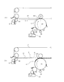
図2は、本発明の画像形成装置の分散剤の回収機構を説明する図である。
図2(A)は、現像時の動作を説明する図である。
感光体2Yが時計方向に回転しながら帯電部材3Yによって帯電した後に、露光装置4Yによって露光されて静電潜像が形成される。
次いで、現像装置5Yにおいて、キャリア液貯槽40Yから供給されるキャリア液41とトナー貯槽50Yから供給されるトナー51Yは、現像剤調製槽25Yにおいて所定の濃度の現像剤に調製されて現像剤容器30Yに供給される。供給された液体現像剤31Yは、供給ローラ32Y、アニロクスローラ33Yによって供給されて現像ローラ35Yによって静電潜像が現像される。
FIG. 2 is a view for explaining the recovery mechanism of the dispersant of the image forming apparatus of the present invention.
FIG. 2A is a diagram for explaining the operation during development.
After the
Next, in the developing
また、静電潜像を現像した感光体2Y上の現像剤像は、スクイーズ装置7Yによってスクイーズされて余剰のキャリア液が回収されて、回収された現像液は現像液調製槽25Yへ回収される。
次いで、形成された現像剤像は転写装置10Yにおいてバックアップローラ15Yによって転写バイアスを与えられて中間転写媒体である中間転写ベルト18上に転写され、転写装置において紙等の転写材に転写された後に定着装置によって定着されて画像形成装置から取り出される。
Further, the developer image on the
Next, the formed developer image is transferred on the
転写後の感光体2上に残留した残留現像剤70は感光体クリーニング装置9Yに設けた感光体クリーナ91によって除去され、感光体クリーナ回収液貯留容器92に回収された後に現像剤回収容器90へ送られる。
残留現像剤70中の固形成分は感光体クリーニング装置9Yによって除去される。
The
The solid component in the
また、中間転写ベルトからの転写終了後に中間転写ベルト18上に残った残留現像剤70は中間転写ベルトクリーニング装置17に設けた中間転写ベルトクリーニング部材17Aによって除去され中間転写ベルトクリーニング容器17Bに回収された後に現像剤回収容器90へ送られる。
残留現像剤70中の固形成分は中間転写ベルトクリーニング装置17によって除去されるがキャリア液中に溶解する分散剤は、中間転写ベルトクリーニング装置17に設けた中間転写ベルトクリーニング部材17Aでは完全には除去されずに中間転写ベルト18表面に分散剤を含有した残留液72となって残留する。
Further, the
The solid component in the
これに対して、本発明の画像形成装置においては、図2(B)に示すように、現像装置5Yが感光体2Yの静電潜像を現像した後に、分散剤回収液塗布手段6に設けた塗布ローラ65から中間転写ベルト18に分散剤回収液61を塗布する。
中間転写ベルト18上の残留液72中の分散剤は、塗布された分散剤回収液61に溶解し、更に分散剤回収液によって溶解および希釈されて分散剤液希釈層74を形成する。
On the other hand, in the image forming apparatus of the present invention, as shown in FIG. 2B, after the developing
The dispersant in the
中間転写ベルト18の回転に伴って分散剤希釈層74は、中間転写ベルトクリーニング装置17に達して中間転写ベルトクリーニング部材17Aで除去され、中間転写ベルトクリーニング容器17Bに回収された後に現像剤回収容器90へと回収される。
As the
中間転写ベルトへの分散剤回収液の塗布および分散剤回収プロセスが終了すると、図2(A)に示すように現像プロセスを実行する。 When the application of the dispersant recovery liquid to the intermediate transfer belt and the dispersant recovery process are completed, a development process is executed as shown in FIG.
以上のように、図2(A)で示す現像プロセスと図2(B)で示す分散剤回収プロセスを繰り返すことによって高品質の画像形成を行うことができる。分散剤回収プロセスは、現像プロセスと交互に行っても良いが、複数回の現像プロセスに対して一回を行っても良く、現像プロセスの開始あるいは終了時に行っても良い。 As described above, high-quality image formation can be performed by repeating the development process shown in FIG. 2A and the dispersant recovery process shown in FIG. The dispersant recovery process may be performed alternately with the development process, but may be performed once for a plurality of development processes, or may be performed at the start or end of the development process.
図3は、本発明の画像形成装置における分散剤の塗布部の位置関係を説明する図である。
図3(A)は、分散剤回収液塗布手段6の塗布ローラ65と一次転写部10のニップ部間の距離L1と、感光体2Yの露光装置4Yから中間転写ベルトへの転写部10のニップ部間の距離L2の関係を示す図であり、ページ毎に画像を形成する場合の印字可能領域の後端の相当位置の静電潜像が感光体2Yに形成される状態を示している。
すなわち、L2は、画像後端の相当する静電潜像の後端位置が露光した際に、中間転写ベルトへの転写装置10Yのニップ部から画像後端までの距離を示している。
一方、L1は、塗布ローラ65からニップ部までの距離を表していている。
FIG. 3 is a view for explaining the positional relationship of the application part of the dispersant in the image forming apparatus of the present invention.
3A shows a distance L1 between the coating
That is, L2 indicates the distance from the nip portion of the
On the other hand, L1 represents the distance from the
したがって、L1>L2との関係とすることによって、中間転写ベルト18上の画像後端に相当する位置に分散剤回収液が塗布される部分を重ならないようにし、中間転写ベルト18上に分散剤回収液が塗布されない部分の長さを大きくすることなく分散剤回収液を塗布することが可能となる。
Therefore, the relationship of L1> L2 is set so that the portion where the dispersant recovery liquid is applied does not overlap the position corresponding to the rear end of the image on the
図3(B)は、感光体2Y上に形成された現像剤31Yからなる現像剤像の画像後端位置Aが中間転写ベルトへの転写装置10において、中間転写ベルト18上の画像後端位置Bに転写されるのに対して、分散剤回収液61の塗布部先端位置Cは、Bのわずか後方に位置することを示している。
すなわち、中間転写媒体18に最初に画像が転写される感光体2Y上の現像剤像が転写される回転可能な中間転写ベルト18上の画像形成位置であるBよりも上流側であるC位置から、塗布手段6の分散剤回収液塗布ローラ65によって液体現像剤中の分散剤が溶解可能な分散剤回収液の塗布を開始するように制御することを示している。
FIG. 3B shows an image rear end position A of the developer image made of the
That is, from the position C upstream of the image forming position B on the rotatable
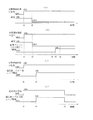
図4は、本発明の画像形成装置における制御方法を説明する図である。
図4(A)は、分散剤回収液の塗布動作をt1で開始した後に、露光動作をt2で終了した例を示している。
例えば、以下の条件では、分散剤回収液の塗布部の先端が、中間転ベルトへの転写ニップに到達するまでに、印字画像後端が転写ニップを通過する必要があるので、t1とt2の差は、0.7秒が必要となる。
印字速度 A4用紙 1分あたり40枚 214mm/秒
塗布ローラと中間転写媒体への転写ニップの距離 140mm
露光部と一次転写部との距離 125.6mm
FIG. 4 is a diagram illustrating a control method in the image forming apparatus of the present invention.
FIG. 4A shows an example in which the exposure operation is ended at t2 after the application operation of the dispersant recovery liquid is started at t1.
For example, under the following conditions, the trailing edge of the print image needs to pass through the transfer nip before the leading edge of the application part of the dispersant recovery liquid reaches the transfer nip to the intermediate transfer belt. The difference requires 0.7 seconds.
Printing
Distance between exposed area and primary transfer area 125.6mm
図4(B)は、転写材への転写ローラと中間転写ベルト間のニップを、画像後端が通過するt4が通過した後、t5において転写材への転写ローラと中間転写ベルトとのニップを開放することを示している。更に、t6において分散剤回収液の塗布部の先端が通過した後も、分散剤回収液の塗布部が通過が終了までは開放状態を維持し、分散剤回収液の塗布部が通過した後、所定の時間経過した時点で所定のニップとしている。 FIG. 4B shows the nip between the transfer roller to the transfer material and the intermediate transfer belt, and after the passage of t4 through which the rear end of the image passes, the nip between the transfer roller to the transfer material and the intermediate transfer belt at t5. It shows opening. Furthermore, even after the tip of the application part of the dispersant recovery liquid has passed at t6, the application part of the dispersant recovery liquid remains open until the end of passing, and after the application part of the dispersant recovery liquid has passed, A predetermined nip is established when a predetermined time has elapsed.
図4(C)は、中間転写ベルトへの転写部における感光体−中間転写ベルト間ニップ開放時点t3を説明する図であり、t3は、分散剤回収液の塗布開始時点t1から、中間転写媒体への転写ニップに分散剤回収液の塗布部の先端が到達する前の時間を加えた時間よりも短い時間に設定される。 FIG. 4C is a diagram for explaining a photosensitive member-intermediate transfer belt nip opening time point t3 in the transfer portion to the intermediate transfer belt, where t3 is an intermediate transfer medium from the application start time t1 of the dispersant recovery liquid. The time is set to be shorter than the time obtained by adding the time before the tip of the application part of the dispersant recovery liquid reaches the transfer nip.
図4(D)は、感光体と中間転写ベルトとを当接させた状態で、最終段の感光体が1周以上分散剤回収液が塗布されるt3まで回転させた後に、感光体と中間転写ベルトとのニップを開放し、更に中間転写ベルトにt7までベルト1周分の分散剤回収液の塗布行うことを示している。
その結果、感光体への分散剤回収液塗布による洗浄効果と、その後のベルトへの分散剤回収液塗布によって中間転写ベルトの洗浄を行う洗浄工程を行うことができる。
FIG. 4D shows the state in which the photoconductor and the intermediate transfer belt are in contact with each other, and the photoconductor and the intermediate transfer belt are rotated after the photoconductor at the final stage is rotated for t3 or more to which the dispersant recovery liquid is applied. It shows that the nip with the transfer belt is opened, and further, the recovery liquid for one round of the belt is applied to the intermediate transfer belt until t7.
As a result, it is possible to perform a cleaning process in which the intermediate transfer belt is cleaned by applying the dispersant recovery liquid to the photoreceptor and the subsequent application of the dispersant recovery liquid to the belt.
図5は、本発明にかかる画像形成装置の他の実施の形態を説明する図である。
図1で説明した画像形成装置1は、中間転写ベルト18は互いに離間して配設された駆動ローラ12A、12Bおよび従動ローラ13A、13Bに張架されて図1において反時計回りに回転可能に設けられているのに対して、図5で示すものは、駆動ローラ12、従動ローラ13に張架されて図1において反時計回りに回転可能に設けられている点が相違するものであるが、図1に示した画像形成装置と同様に画像形成される。
FIG. 5 is a diagram for explaining another embodiment of the image forming apparatus according to the present invention.
In the
図6は、本発明にかかる画像形成装置の他の実施の形態を説明する図である。
分散剤回収液としてキャリア液を塗布手段に供給して分散剤を溶解、希釈して分離する画像形成装置を説明する図である。
液体現像剤の調製のために設けたキャリア液貯槽40Yから供給されるキャリア液41を分散剤回収液として利用する点が図1に示した画像形成装置と相違している。
画像形成装置1は、実施例1で示したものと同様に、各感光体2Y,2M,2C,2Kがタンデム型に配置されており、分散剤回収液塗布手段として設けたキャリア液塗布手段7の塗布ローラ45が中間転写ベルト18に当接してキャリア液41を分散剤回収液として塗布するものである。
FIG. 6 is a diagram for explaining another embodiment of the image forming apparatus according to the present invention.
It is a figure explaining the image forming apparatus which supplies a carrier liquid as a dispersing agent collection | recovery liquid to an application | coating means, dissolves, dilutes, and separates a dispersing agent.
1 is different from the image forming apparatus shown in FIG. 1 in that the
In the
また、キャリア液41は、キャリア液貯槽40Yから補給されてキャリア液容器42内の供給ローラ43と規制ブレード44によって所定の厚みとした後に、キャリア液塗布ローラ45に供給される。
Further, the
キャリア液塗布ローラ45によって中間転写ベルト18に塗布されたキャリア液41は、中間転写ベルト上に残留した分散剤を希釈した分散剤希釈層を形成する。
The
分散剤希釈層は、中間転写ベルトクリーニング装置17に達して中間転写ベルトクリーニング部材17Aで除去され、中間転写ベルトクリーニング容器17Bに回収された後に現像剤回収容器90へ送られる。
このように図6に示してものでは、液体現像剤の調製に準備されたキャリア液を使用するので、液体現像剤の調製用キャリア液とは別個に分散剤回収用のキャリア液を準備する必要はない。
The dispersant diluted layer reaches the intermediate transfer
As shown in FIG. 6, since the carrier liquid prepared for the preparation of the liquid developer is used, it is necessary to prepare a carrier liquid for collecting the dispersant separately from the carrier liquid for preparing the liquid developer. There is no.
図7は、本発明にかかる画像形成装置の他の実施の形態を説明する図である。
図6で説明した、画像形成装置1は、中間転写ベルト18は互いに離間して配設された駆動ローラ12A、12Bおよび従動ローラ13A、13Bに張架されて図7において反時計回りに回転可能に設けられているのに対して、図7で示すものは、駆動ローラ12、従動ローラ13に張架されて図7において反時計回りに回転可能に設けられている点が相違するものであるが、図6に示した画像形成装置と同様に画像形成される。
FIG. 7 is a diagram for explaining another embodiment of the image forming apparatus according to the present invention.
In the
図8は、本発明にかかる画像形成装置の他の実施の形態を説明する図である。
図8で示す画像形成装置は、分散剤回収液、各色の液体現像剤調製用キャリア液がすべて共通のキャリア液貯槽40から供給されるキャリア液41を使用した点が図7で示したものとは相違している。
キャリア液貯槽40から、キャリア液が、分散剤回収液塗布手段6に供給されて、中間転写ベルト18の表面に塗布されるとともに、各色の液体現像剤調製槽25Y,25M,25C,25Kへと供給されてトナーの混合されて所定の濃度の液体現像剤の調製に利用されることを特徴としている。
図8の画像形成装置では、分散剤回収液を別途準備したり、あるいは各色毎にキャリア液を準備することが不要であると言う特徴を有している。
FIG. 8 is a diagram for explaining another embodiment of the image forming apparatus according to the present invention.
The image forming apparatus shown in FIG. 8 uses the
From the carrier
The image forming apparatus of FIG. 8 has a feature that it is not necessary to separately prepare a dispersant recovery liquid or to prepare a carrier liquid for each color.
1…画像形成装置、2Y,2M,2C,2K…各色の感光体、5Y,5M,5C,5K…各色の現像装置、6…分散剤回収液塗布手段、7…キャリア液塗布手段、10Y,10M,10C,10K…中間転写媒体への転写装置、9Y,9M,9C,9K…感光体クリーニング装置、14…転写材、15Y,15M,15C,15K…バックアップローラ、17…中間転写ベルトクリーニング装置、18…中間転写ベルト、19…転写材への転写装置、25Y,25M,25C,25K…液体現像液調製槽、31Y,31M,31C,31K…液体現像液、35Y,35M,35C,35K…現像ローラ、41…キャリア液、42Y,45M,45C,45K…キャリア液塗布ローラ、60…分散剤回収液貯槽、61…分散剤回収液、65…分散剤回収液塗布ローラ、90…現像液回収容器、70…残留現像液、74…分散剤液希釈層
DESCRIPTION OF
Claims (7)
トナー、キャリア液、およびキャリア液に溶解可能な分散剤と、を含有する液体現像剤を前記潜像担持体に現像する現像装置と、
前記潜像担持体上に現像された現像剤像が転写される中間転写媒体と、
前記中間転写媒体上の現像剤像を転写材に転写する転写装置と、
前記中間転写媒体上に分散剤回収液を塗布する分散剤回収液塗布手段と、を有し、
前記中間転写媒体上に現像剤像の転写が終了した後に、前記中間転写媒体上に分散剤回収液の塗布手段によって分散剤回収液の塗布を開始するように制御することを特徴とする画像形成装置の制御方法。 A latent image carrier;
A developing device that develops a liquid developer containing toner, carrier liquid, and a dispersant soluble in the carrier liquid onto the latent image carrier;
An intermediate transfer medium onto which the developer image developed on the latent image carrier is transferred;
A transfer device for transferring the developer image on the intermediate transfer medium to a transfer material;
A dispersant recovery liquid applying means for applying a dispersant recovery liquid on the intermediate transfer medium,
The image forming is characterized in that after the transfer of the developer image onto the intermediate transfer medium is completed, the application of the dispersant recovery liquid is controlled to start on the intermediate transfer medium by the application means of the dispersant recovery liquid. Device control method.
静電潜像を現像するためのトナー、キャリア液、およびキャリア液に溶解可能な分散剤と、を含有した液体現像剤を搬送する回転可能な現像ローラが前記潜像担持体の潜像を現像する現像装置と、
前記潜像担持体上の現像剤像が転写される回転可能な中間転写媒体と、
前記中間転写媒体をクリーニングする中間転写媒体クリーニング装置と、
前記中間転写媒体上に分散剤回収液を塗布する塗布手段と、
を設けたことを特徴とする画像形成装置。 A latent image carrier;
A rotatable developing roller for transporting a liquid developer containing a toner for developing an electrostatic latent image, a carrier liquid, and a dispersant soluble in the carrier liquid develops the latent image on the latent image carrier. A developing device,
A rotatable intermediate transfer medium onto which the developer image on the latent image carrier is transferred;
An intermediate transfer medium cleaning device for cleaning the intermediate transfer medium;
Coating means for applying a dispersant recovery liquid on the intermediate transfer medium;
An image forming apparatus comprising:
Priority Applications (2)
| Application Number | Priority Date | Filing Date | Title |
|---|---|---|---|
| JP2008067358A JP2009037202A (en) | 2007-07-12 | 2008-03-17 | Control method of image forming apparatus and image forming apparatus |
| US12/140,124 US8036566B2 (en) | 2007-07-12 | 2008-06-16 | Control method of image forming apparatus and image forming apparatus |
Applications Claiming Priority (2)
| Application Number | Priority Date | Filing Date | Title |
|---|---|---|---|
| JP2007182788 | 2007-07-12 | ||
| JP2008067358A JP2009037202A (en) | 2007-07-12 | 2008-03-17 | Control method of image forming apparatus and image forming apparatus |
Publications (2)
| Publication Number | Publication Date |
|---|---|
| JP2009037202A true JP2009037202A (en) | 2009-02-19 |
| JP2009037202A5 JP2009037202A5 (en) | 2011-03-31 |
Family
ID=40439119
Family Applications (1)
| Application Number | Title | Priority Date | Filing Date |
|---|---|---|---|
| JP2008067358A Withdrawn JP2009037202A (en) | 2007-07-12 | 2008-03-17 | Control method of image forming apparatus and image forming apparatus |
Country Status (1)
| Country | Link |
|---|---|
| JP (1) | JP2009037202A (en) |
Citations (4)
| Publication number | Priority date | Publication date | Assignee | Title |
|---|---|---|---|---|
| JP2001305932A (en) * | 2000-04-25 | 2001-11-02 | Ricoh Co Ltd | Image forming device |
| JP2001337543A (en) * | 2000-05-29 | 2001-12-07 | Ricoh Co Ltd | Wet type image forming device |
| JP2003233258A (en) * | 2002-02-08 | 2003-08-22 | Pfu Ltd | Cleaning mechanism for liquid developing electrophotographic device and control method for it |
| JP2007041368A (en) * | 2005-08-04 | 2007-02-15 | Seiko Epson Corp | Image forming apparatus |
-
2008
- 2008-03-17 JP JP2008067358A patent/JP2009037202A/en not_active Withdrawn
Patent Citations (4)
| Publication number | Priority date | Publication date | Assignee | Title |
|---|---|---|---|---|
| JP2001305932A (en) * | 2000-04-25 | 2001-11-02 | Ricoh Co Ltd | Image forming device |
| JP2001337543A (en) * | 2000-05-29 | 2001-12-07 | Ricoh Co Ltd | Wet type image forming device |
| JP2003233258A (en) * | 2002-02-08 | 2003-08-22 | Pfu Ltd | Cleaning mechanism for liquid developing electrophotographic device and control method for it |
| JP2007041368A (en) * | 2005-08-04 | 2007-02-15 | Seiko Epson Corp | Image forming apparatus |
Similar Documents
| Publication | Publication Date | Title |
|---|---|---|
| US7809307B2 (en) | Image forming apparatus with cleaner having member in contact with a surface of an image carrier | |
| JP5081548B2 (en) | Image forming apparatus | |
| US6496676B1 (en) | Liquid developer system employing a pretransfer station | |
| JP2009014808A (en) | Image forming apparatus, method for controlling image forming apparatus and image forming method | |
| JP2008102319A (en) | Cleaning device and image forming device | |
| JP5447825B2 (en) | Image forming method and image forming apparatus | |
| JP2001242717A (en) | Developing device | |
| US8036566B2 (en) | Control method of image forming apparatus and image forming apparatus | |
| JP2007121808A (en) | Image forming apparatus | |
| JP5175565B2 (en) | Liquid developing apparatus and wet image forming apparatus | |
| JP4585478B2 (en) | Image forming apparatus | |
| JP2009003254A (en) | Image forming apparatus, method for controlling image forming apparatus and image forming method | |
| JP2009037202A (en) | Control method of image forming apparatus and image forming apparatus | |
| JP4528201B2 (en) | Fixing liquid applying apparatus and image forming apparatus | |
| JP2009003268A (en) | Image forming apparatus, method for controlling image forming apparatus and image forming method | |
| JP2011107203A (en) | Image forming method and image forming apparatus | |
| JP5177381B2 (en) | Image forming apparatus and image forming method | |
| JP2007148083A (en) | Image forming apparatus | |
| JP2008070810A (en) | Electrifying device, process unit and image forming apparatus | |
| JP2008170702A (en) | Liquid development agent and image forming device using it | |
| JP4282570B2 (en) | Image forming apparatus | |
| JP2009053405A (en) | Image forming apparatus and image forming method | |
| JP2005338559A (en) | Image forming apparatus | |
| JP2009198577A (en) | Wet type image forming apparatus | |
| JP2007121807A (en) | Image forming apparatus |
Legal Events
| Date | Code | Title | Description |
|---|---|---|---|
| A521 | Written amendment |
Free format text: JAPANESE INTERMEDIATE CODE: A523 Effective date: 20110209 |
|
| A621 | Written request for application examination |
Free format text: JAPANESE INTERMEDIATE CODE: A621 Effective date: 20110209 |
|
| A131 | Notification of reasons for refusal |
Effective date: 20120803 Free format text: JAPANESE INTERMEDIATE CODE: A131 |
|
| A521 | Written amendment |
Free format text: JAPANESE INTERMEDIATE CODE: A523 Effective date: 20121002 |
|
| A131 | Notification of reasons for refusal |
Free format text: JAPANESE INTERMEDIATE CODE: A131 Effective date: 20130419 |
|
| A761 | Written withdrawal of application |
Effective date: 20130604 Free format text: JAPANESE INTERMEDIATE CODE: A761 |